EP3524929B1 - Projection system - Google Patents
Projection system Download PDFInfo
- Publication number
- EP3524929B1 EP3524929B1 EP19155926.9A EP19155926A EP3524929B1 EP 3524929 B1 EP3524929 B1 EP 3524929B1 EP 19155926 A EP19155926 A EP 19155926A EP 3524929 B1 EP3524929 B1 EP 3524929B1
- Authority
- EP
- European Patent Office
- Prior art keywords
- image
- light
- invisible light
- projection system
- infrared light
- Prior art date
- Legal status (The legal status is an assumption and is not a legal conclusion. Google has not performed a legal analysis and makes no representation as to the accuracy of the status listed.)
- Active
Links
- 238000005259 measurement Methods 0.000 claims description 86
- 239000003550 marker Substances 0.000 claims description 51
- 238000001514 detection method Methods 0.000 claims description 32
- 238000003384 imaging method Methods 0.000 claims description 29
- 230000010287 polarization Effects 0.000 claims description 26
- 238000009827 uniform distribution Methods 0.000 claims description 5
- 230000003287 optical effect Effects 0.000 description 15
- 230000000694 effects Effects 0.000 description 9
- 230000006870 function Effects 0.000 description 9
- 238000009792 diffusion process Methods 0.000 description 8
- 238000013507 mapping Methods 0.000 description 8
- 238000005516 engineering process Methods 0.000 description 7
- 238000010586 diagram Methods 0.000 description 6
- 238000000034 method Methods 0.000 description 6
- 238000009826 distribution Methods 0.000 description 5
- 238000012545 processing Methods 0.000 description 5
- 230000015572 biosynthetic process Effects 0.000 description 4
- XUIMIQQOPSSXEZ-UHFFFAOYSA-N Silicon Chemical compound [Si] XUIMIQQOPSSXEZ-UHFFFAOYSA-N 0.000 description 3
- BQCADISMDOOEFD-UHFFFAOYSA-N Silver Chemical compound [Ag] BQCADISMDOOEFD-UHFFFAOYSA-N 0.000 description 3
- 238000009434 installation Methods 0.000 description 3
- 229910052710 silicon Inorganic materials 0.000 description 3
- 239000010703 silicon Substances 0.000 description 3
- 229910052709 silver Inorganic materials 0.000 description 3
- 239000004332 silver Substances 0.000 description 3
- 239000011248 coating agent Substances 0.000 description 2
- 238000000576 coating method Methods 0.000 description 2
- 238000005286 illumination Methods 0.000 description 2
- 239000000463 material Substances 0.000 description 2
- 229910052751 metal Inorganic materials 0.000 description 2
- 239000002184 metal Substances 0.000 description 2
- 239000000843 powder Substances 0.000 description 2
- 239000004065 semiconductor Substances 0.000 description 2
- 230000035945 sensitivity Effects 0.000 description 2
- 238000001429 visible spectrum Methods 0.000 description 2
- GYHNNYVSQQEPJS-UHFFFAOYSA-N Gallium Chemical compound [Ga] GYHNNYVSQQEPJS-UHFFFAOYSA-N 0.000 description 1
- 238000013459 approach Methods 0.000 description 1
- 238000006073 displacement reaction Methods 0.000 description 1
- 238000000605 extraction Methods 0.000 description 1
- 229910052733 gallium Inorganic materials 0.000 description 1
- 229910052732 germanium Inorganic materials 0.000 description 1
- GNPVGFCGXDBREM-UHFFFAOYSA-N germanium atom Chemical compound [Ge] GNPVGFCGXDBREM-UHFFFAOYSA-N 0.000 description 1
- 229910052736 halogen Inorganic materials 0.000 description 1
- 150000002367 halogens Chemical class 0.000 description 1
- 230000002452 interceptive effect Effects 0.000 description 1
- 230000001678 irradiating effect Effects 0.000 description 1
- 230000001151 other effect Effects 0.000 description 1
- 230000005855 radiation Effects 0.000 description 1
- 230000004044 response Effects 0.000 description 1
- 239000007787 solid Substances 0.000 description 1
- 230000003068 static effect Effects 0.000 description 1
Images


Classifications
-
- H—ELECTRICITY
- H04—ELECTRIC COMMUNICATION TECHNIQUE
- H04N—PICTORIAL COMMUNICATION, e.g. TELEVISION
- H04N9/00—Details of colour television systems
- H04N9/12—Picture reproducers
- H04N9/31—Projection devices for colour picture display, e.g. using electronic spatial light modulators [ESLM]
- H04N9/3191—Testing thereof
- H04N9/3194—Testing thereof including sensor feedback
-
- G—PHYSICS
- G01—MEASURING; TESTING
- G01B—MEASURING LENGTH, THICKNESS OR SIMILAR LINEAR DIMENSIONS; MEASURING ANGLES; MEASURING AREAS; MEASURING IRREGULARITIES OF SURFACES OR CONTOURS
- G01B11/00—Measuring arrangements characterised by the use of optical techniques
- G01B11/24—Measuring arrangements characterised by the use of optical techniques for measuring contours or curvatures
- G01B11/25—Measuring arrangements characterised by the use of optical techniques for measuring contours or curvatures by projecting a pattern, e.g. one or more lines, moiré fringes on the object
-
- G—PHYSICS
- G01—MEASURING; TESTING
- G01S—RADIO DIRECTION-FINDING; RADIO NAVIGATION; DETERMINING DISTANCE OR VELOCITY BY USE OF RADIO WAVES; LOCATING OR PRESENCE-DETECTING BY USE OF THE REFLECTION OR RERADIATION OF RADIO WAVES; ANALOGOUS ARRANGEMENTS USING OTHER WAVES
- G01S17/00—Systems using the reflection or reradiation of electromagnetic waves other than radio waves, e.g. lidar systems
- G01S17/02—Systems using the reflection of electromagnetic waves other than radio waves
- G01S17/06—Systems determining position data of a target
-
- G—PHYSICS
- G01—MEASURING; TESTING
- G01S—RADIO DIRECTION-FINDING; RADIO NAVIGATION; DETERMINING DISTANCE OR VELOCITY BY USE OF RADIO WAVES; LOCATING OR PRESENCE-DETECTING BY USE OF THE REFLECTION OR RERADIATION OF RADIO WAVES; ANALOGOUS ARRANGEMENTS USING OTHER WAVES
- G01S17/00—Systems using the reflection or reradiation of electromagnetic waves other than radio waves, e.g. lidar systems
- G01S17/86—Combinations of lidar systems with systems other than lidar, radar or sonar, e.g. with direction finders
-
- G—PHYSICS
- G01—MEASURING; TESTING
- G01S—RADIO DIRECTION-FINDING; RADIO NAVIGATION; DETERMINING DISTANCE OR VELOCITY BY USE OF RADIO WAVES; LOCATING OR PRESENCE-DETECTING BY USE OF THE REFLECTION OR RERADIATION OF RADIO WAVES; ANALOGOUS ARRANGEMENTS USING OTHER WAVES
- G01S17/00—Systems using the reflection or reradiation of electromagnetic waves other than radio waves, e.g. lidar systems
- G01S17/88—Lidar systems specially adapted for specific applications
- G01S17/89—Lidar systems specially adapted for specific applications for mapping or imaging
-
- G—PHYSICS
- G01—MEASURING; TESTING
- G01S—RADIO DIRECTION-FINDING; RADIO NAVIGATION; DETERMINING DISTANCE OR VELOCITY BY USE OF RADIO WAVES; LOCATING OR PRESENCE-DETECTING BY USE OF THE REFLECTION OR RERADIATION OF RADIO WAVES; ANALOGOUS ARRANGEMENTS USING OTHER WAVES
- G01S7/00—Details of systems according to groups G01S13/00, G01S15/00, G01S17/00
- G01S7/48—Details of systems according to groups G01S13/00, G01S15/00, G01S17/00 of systems according to group G01S17/00
- G01S7/4802—Details of systems according to groups G01S13/00, G01S15/00, G01S17/00 of systems according to group G01S17/00 using analysis of echo signal for target characterisation; Target signature; Target cross-section
-
- G—PHYSICS
- G01—MEASURING; TESTING
- G01S—RADIO DIRECTION-FINDING; RADIO NAVIGATION; DETERMINING DISTANCE OR VELOCITY BY USE OF RADIO WAVES; LOCATING OR PRESENCE-DETECTING BY USE OF THE REFLECTION OR RERADIATION OF RADIO WAVES; ANALOGOUS ARRANGEMENTS USING OTHER WAVES
- G01S7/00—Details of systems according to groups G01S13/00, G01S15/00, G01S17/00
- G01S7/48—Details of systems according to groups G01S13/00, G01S15/00, G01S17/00 of systems according to group G01S17/00
- G01S7/499—Details of systems according to groups G01S13/00, G01S15/00, G01S17/00 of systems according to group G01S17/00 using polarisation effects
-
- G—PHYSICS
- G03—PHOTOGRAPHY; CINEMATOGRAPHY; ANALOGOUS TECHNIQUES USING WAVES OTHER THAN OPTICAL WAVES; ELECTROGRAPHY; HOLOGRAPHY
- G03B—APPARATUS OR ARRANGEMENTS FOR TAKING PHOTOGRAPHS OR FOR PROJECTING OR VIEWING THEM; APPARATUS OR ARRANGEMENTS EMPLOYING ANALOGOUS TECHNIQUES USING WAVES OTHER THAN OPTICAL WAVES; ACCESSORIES THEREFOR
- G03B17/00—Details of cameras or camera bodies; Accessories therefor
- G03B17/48—Details of cameras or camera bodies; Accessories therefor adapted for combination with other photographic or optical apparatus
- G03B17/54—Details of cameras or camera bodies; Accessories therefor adapted for combination with other photographic or optical apparatus with projector
-
- G—PHYSICS
- G03—PHOTOGRAPHY; CINEMATOGRAPHY; ANALOGOUS TECHNIQUES USING WAVES OTHER THAN OPTICAL WAVES; ELECTROGRAPHY; HOLOGRAPHY
- G03B—APPARATUS OR ARRANGEMENTS FOR TAKING PHOTOGRAPHS OR FOR PROJECTING OR VIEWING THEM; APPARATUS OR ARRANGEMENTS EMPLOYING ANALOGOUS TECHNIQUES USING WAVES OTHER THAN OPTICAL WAVES; ACCESSORIES THEREFOR
- G03B21/00—Projectors or projection-type viewers; Accessories therefor
- G03B21/14—Details
- G03B21/26—Projecting separately subsidiary matter simultaneously with main image
-
- G—PHYSICS
- G06—COMPUTING; CALCULATING OR COUNTING
- G06F—ELECTRIC DIGITAL DATA PROCESSING
- G06F3/00—Input arrangements for transferring data to be processed into a form capable of being handled by the computer; Output arrangements for transferring data from processing unit to output unit, e.g. interface arrangements
- G06F3/01—Input arrangements or combined input and output arrangements for interaction between user and computer
- G06F3/011—Arrangements for interaction with the human body, e.g. for user immersion in virtual reality
-
- G—PHYSICS
- G06—COMPUTING; CALCULATING OR COUNTING
- G06F—ELECTRIC DIGITAL DATA PROCESSING
- G06F3/00—Input arrangements for transferring data to be processed into a form capable of being handled by the computer; Output arrangements for transferring data from processing unit to output unit, e.g. interface arrangements
- G06F3/01—Input arrangements or combined input and output arrangements for interaction between user and computer
- G06F3/03—Arrangements for converting the position or the displacement of a member into a coded form
- G06F3/041—Digitisers, e.g. for touch screens or touch pads, characterised by the transducing means
- G06F3/0416—Control or interface arrangements specially adapted for digitisers
- G06F3/04166—Details of scanning methods, e.g. sampling time, grouping of sub areas or time sharing with display driving
-
- G—PHYSICS
- G06—COMPUTING; CALCULATING OR COUNTING
- G06F—ELECTRIC DIGITAL DATA PROCESSING
- G06F3/00—Input arrangements for transferring data to be processed into a form capable of being handled by the computer; Output arrangements for transferring data from processing unit to output unit, e.g. interface arrangements
- G06F3/01—Input arrangements or combined input and output arrangements for interaction between user and computer
- G06F3/03—Arrangements for converting the position or the displacement of a member into a coded form
- G06F3/041—Digitisers, e.g. for touch screens or touch pads, characterised by the transducing means
- G06F3/042—Digitisers, e.g. for touch screens or touch pads, characterised by the transducing means by opto-electronic means
- G06F3/0425—Digitisers, e.g. for touch screens or touch pads, characterised by the transducing means by opto-electronic means using a single imaging device like a video camera for tracking the absolute position of a single or a plurality of objects with respect to an imaged reference surface, e.g. video camera imaging a display or a projection screen, a table or a wall surface, on which a computer generated image is displayed or projected
-
- G—PHYSICS
- G06—COMPUTING; CALCULATING OR COUNTING
- G06T—IMAGE DATA PROCESSING OR GENERATION, IN GENERAL
- G06T7/00—Image analysis
- G06T7/50—Depth or shape recovery
- G06T7/521—Depth or shape recovery from laser ranging, e.g. using interferometry; from the projection of structured light
-
- H—ELECTRICITY
- H04—ELECTRIC COMMUNICATION TECHNIQUE
- H04N—PICTORIAL COMMUNICATION, e.g. TELEVISION
- H04N9/00—Details of colour television systems
- H04N9/12—Picture reproducers
- H04N9/31—Projection devices for colour picture display, e.g. using electronic spatial light modulators [ESLM]
- H04N9/3141—Constructional details thereof
- H04N9/3147—Multi-projection systems
-
- H—ELECTRICITY
- H04—ELECTRIC COMMUNICATION TECHNIQUE
- H04N—PICTORIAL COMMUNICATION, e.g. TELEVISION
- H04N9/00—Details of colour television systems
- H04N9/12—Picture reproducers
- H04N9/31—Projection devices for colour picture display, e.g. using electronic spatial light modulators [ESLM]
- H04N9/3179—Video signal processing therefor
- H04N9/3185—Geometric adjustment, e.g. keystone or convergence
-
- G—PHYSICS
- G06—COMPUTING; CALCULATING OR COUNTING
- G06F—ELECTRIC DIGITAL DATA PROCESSING
- G06F2203/00—Indexing scheme relating to G06F3/00 - G06F3/048
- G06F2203/041—Indexing scheme relating to G06F3/041 - G06F3/045
- G06F2203/04101—2.5D-digitiser, i.e. digitiser detecting the X/Y position of the input means, finger or stylus, also when it does not touch, but is proximate to the digitiser's interaction surface and also measures the distance of the input means within a short range in the Z direction, possibly with a separate measurement setup
-
- H—ELECTRICITY
- H04—ELECTRIC COMMUNICATION TECHNIQUE
- H04N—PICTORIAL COMMUNICATION, e.g. TELEVISION
- H04N5/00—Details of television systems
- H04N5/30—Transforming light or analogous information into electric information
Definitions
- the present disclosure relates to a projection system that projects an image fit for a shape, a position, and the like of an object based on three-dimensional measurements of the object and the like.
- the systems and methods described in US 2013/0215235 Al include a device that can scan the surrounding environment and construct a 3D image, map, or representation of the surrounding environment using, for example, invisible light projected into the environment.
- the device can also project into the surrounding environment one or more visible radiation pattern patterns (e.g., a virtual object, text, graphics, images, symbols, color patterns, etc.) that are based at least in part on the 3D map of the surrounding environment.
- visible radiation pattern patterns e.g., a virtual object, text, graphics, images, symbols, color patterns, etc.
- a real-time measuring and projection apparatus comprises: a pattern light projector irradiating a projection target with pattern light containing a pattern image; an imaging device acquiring a picked-up image of the projection target irradiated with the pattern light electronically per pixel with predetermined exposure time; and an arithmetic device calculating a distance to an individual point of the projection target by comparing the picked-up image with data on the pattern image, the imaging device temporally shifting timing of start and end of the predetermined exposure time among pixels.
- the system includes a computing device, a projector and a camera.
- the computing device stores a digital model of an object, and illumination data having lighting parameters and a reference to the digital model.
- the projector or another light source, projects structured light onto the projection area, and the camera simultaneously captures an image of the projection area.
- the computing device receives the captured image, determines a position and orientation of the object by comparing the digital model to the captured image, and then generates a canvas image including a region matching the determined position and orientation of the object.
- the projector projects the canvas image onto the projection area. A predefined portion of the object corresponding to the reference in the illumination data is thereby illuminated according to the lighting parameters.
- a projection system includes an invisible light projector, a background member, an imaging unit, an image generator, and a visible light projector.
- the invisible light projector projects a predetermined invisible light image onto the object via invisible light.
- the background member is disposed behind the object in a direction of the invisible light emitted from the invisible light projector.
- the imaging unit captures an image of the invisible light projected from the invisible light projector.
- the image generator measures a shape of the object based on the image captured by the imaging unit to generate image data showing image content for projection onto the object in accordance with the measured shape.
- the visible light projector projects the image content shown by the image data onto the object via visible light.
- the background member has a light shielding surface that does not diffusely reflect the invisible light incident thereon.
- JP 2015-173431 A discloses a projection system for projection mapping for projection mapping to project image content onto a structure such as a building.
- a projection apparatus radiates, onto the structure, image light showing image content and pattern light showing a pattern image in which projection coordinates in a projection coordinate system are coded.
- a capture apparatus captures an image of the pattern image projected onto the structure.
- the projection system enables projection mapping while the image content is positioned for the structure.
- the present disclosure provides a projection system that projects an image and that can facilitate obtaining information on the object while obtaining three-dimensional measurements of the object.
- the projection system according to the present disclosure projects an image based on a measurement of the object.
- the projection system is defined in claim 1.
- the projection system according the present disclosure captures the invisible light image having the light amount more than or equal to the offset value during projection of the image. This configuration enables the projection system to facilitate obtaining the information on the object while obtaining the three-dimensional measurements of the object.
- FIG. 1 is a block diagram illustrating a configuration of a projection system 1 according to this embodiment.
- the projection system 1 includes a visible light projector 2, an infrared light projector 3, an infrared light illuminator 30, a camera 4, a controller 5, and a screen 10.
- the projection system 1 is a projection mapping system that projects visible light images onto a subject 6 such as a person or the like for staging for example.
- the projection system 1 obtains three-dimensional measurements of the subject 6 using the infrared light projector 3 and the camera 4 to allow the visible light projector 2 to project an image 71 with visible light in response to a three-dimensional shape and other measurements of the subject 6.
- the projection system 1 of this embodiment performs two-dimensional detection for successively obtaining a two-dimensional position of a marker 61 held by the subject 6 to get the image 71 to follow the motion of the subject 6 with a high degree of precision.
- the projection system 1 uses the infrared light illuminator 30 in addition to the infrared light projector 3 and other components for the three-dimensional measurement described above to make the two-dimensional detection of the marker 61 faster.
- the marker 61 indicates a reference position at which the image 71 is projected on the subject 6.
- the marker 61 is attached to a portion of the subject 6 which is supposed to move fast, e.g. a limb of a person.
- the marker 61 is made up of a reflecting component having retroreflectivity.
- the visible light projector 2 is a projector using the DLP, 3LCD, or LCOS technology, for example.
- the visible light projector 2 emits visible light based on image signals (image data) entering from the controller 5 so as to project the image 71 that contains various image contents, for example.
- the visible light projector 2 is an example of visible light projectors according to this embodiment. As shown in Fig. 1 , the visible light projector 2 includes a visible light source 21, a spatial light modulator 22, and a projection optical system 23.
- the visible light source 21 includes a plurality of luminous elements (e.g. LEDs) that emit red, green, and blue rays of light, respectively.
- the visible light source 21 may include a sole monochrome luminous element or a white color luminous element appropriately depending on a projection method adopted for the visible light projector 2.
- the luminous elements may be laser diodes, halogen or other lamps.
- the spatial light modulator 22 is made up of three spatial light modulation devices corresponding to RGB, for example.
- the spatial light modulation devices can be DMD or LCD chips, or other devices.
- the spatial light modulator 22 need not necessarily be made up of the three spatial light modulation devices, but may be made up of a sole spatial light modulation device, for example.
- the projection optical system 23 includes a zoom lens for defining an angle of view for the visible light projector 2 and a focus lens for focus adjustment.
- the infrared light projector 3 is a projector using the DLP, LCD, or LCOS technology, for example.
- the infrared light projector 3 projects a predetermined infrared measurement pattern described later and the like based on the image signals (image data) entering from the controller 5, for example.
- the infrared light projector 3 and the infrared light illuminator 30 according to this embodiment are examples of invisible light projectors that project invisible light images with invisible light.
- This embodiment employs infrared light as an instance of invisible light. Instead, any invisible light, e.g. ultraviolet light, may be used, other than infrared light.
- the infrared light projector 3 includes an infrared light source 31, a spatial light modulation device 32, and a projection optical system 33.
- the infrared light source 31 emits infrared light having a peak wavelength of 800 nm to 900 nm, for example.
- the infrared light source 31 includes a luminous element such as a laser diode.
- the luminous element of the infrared light source 31 may be an LED, a lamp, or another element.
- the spatial light modulation device 32 is made up of a DMD or LCD chip, or another device.
- the spatial light modulation device 32 forms an image on an image formation surface thereof based on the image signals entering from the controller 5 or another unit.
- Infrared light emitted from the infrared light source 31 is incident on the image formation surface of the spatial light modulation device 32 to be spatially modulated.
- the projection optical system 33 includes a zoom lens for defining an angle of view for the infrared light projector 3 and a focus lens for focus adjustment.
- the infrared light illuminator 30 is an example of illuminators that projects infrared light as invisible light.
- the infrared light illuminator 30 includes a light source such as an LED or a lamp.
- the infrared light illuminator 30 emits infrared light having a peak wavelength of 800 nm to 900 nm, for example.
- the infrared light illuminator 30 and the infrared light projector 3 are arranged to be able to irradiate an identical area with infrared light, for example.
- the infrared light illuminator 30 and the camera 4 are arranged in close proximity to each other and oriented in almost the same direction such that their respective optical axes align with each other.
- the projectors 2 and 3 are arranged to project images onto an identical area, for example.
- the projectors 2 and 3 may be optically coupled each other such that their respective optical axes align with each other.
- the projectors may each include a dichroic mirror or any other device that transmits visible light while reflecting infrared light or that reflects visible light while transmitting infrared light.
- the projection optical systems 23 and 33 may be integrated each other.
- the infrared light projector 3 and the visible light projector 2 may be integrated each other to act as a single instrument.
- the camera 4 is disposed at a position that allows capture of an image of an area onto which invisible light images are projected from the infrared light projector 3 and another component.
- the camera 4 captures a measurement pattern that is projected onto the subject 6 with infrared light and generates an image of the captured pattern.
- the camera 4 outputs imaging data, i.e. data indicating the image of the captured pattern, to the controller 5.
- the camera 4 is an example of any imaging device for use in the projection system 1. As shown in Fig. 1 , the camera 4 includes an image pick-up device 41, an imaging lens 42, and a visible light cut-off filter 43.
- the image pick-up device 41 includes a solid-state image sensing device, e.g. a CCD or CMOS image sensor made primarily from silicon.
- the image pick-up device 41 has an imaging surface that contains a plurality of arranged pixel circuits for receiving light.
- the principal material used for the image pick-up device 41 may be any material, such as germanium or gallium, other than silicon.
- the imaging lens 42 includes a zoom lens for defining an angle of view for the camera 4 and a focus lens for focus adjustment.
- the visible light cut-off filter 43 is a bandpass filter or a longpass filter that transmits infrared light components and absorbs visible light components of incident light.
- the visible light cut-off filter 43 is attached to the imaging lens 42, for example.
- the visible light cut-off filter 43 is an example of any wavelength selector used for the camera 4 to selectively transmit infrared light.
- the visible light cut-off filter 43 may be integrated with the imaging lens 42 through means such as forming a coating or a diffraction grating on the imaging lens 42. Alternatively, the visible light cut-off filter 43 may be built into an image formation surface (that is, imaging surface) or any other part of the image pick-up device 41. The visible light cut-off filter 43 may be configured to reflect visible light components in place of or in addition to absorbing visible light components.
- the controller 5 is a controller that controls components of the projection system 1.
- the controller 5 includes a central processing unit (CPU) or a micro processing unit (MPU) to implement predetermined functions in collaboration with software, for example.
- the controller 5 includes an image generator 50 and a storage 51.
- the controller 5 is an example of any controller for use in the projection system 1 according to this embodiment.
- the controller 5 reads data and programs stored in the storage 51 and performs various arithmetic operations to implement functions of every kind. For example, the controller 5 implements functions required for the image generator 50.
- the controller 5 may control timings for acts performed by the components such as the camera 4, the infrared light projector 3, and the visible light projector 2 (e.g. control for synchronization between the units), as well as perform zoom control, focus control, and other control.
- the controller 5 may be a hardware circuit such as an electronic circuit specifically designed for implementing predetermined functions or a reconfigurable electronic circuit.
- the controller 5 may include any of semiconductor integrated circuits, such as a CPU, an MPU, a graphics processing unit (GPU), a microcontroller, a digital signal processor (DSP), a field-programmable gate array (FPGA), and an application specific integrated circuit (ASIC).
- the functions of the controller 5 may be built into respective units of the projection system 1 such as the visible light projector 2.
- the image generator 50 generates image data that specifies the image 71 to be projected from the visible light projector 2.
- the image data needs to be generated such that projection of the image 71 is allowed to follow the motion of the subject 6.
- the controller 5 obtains three-dimensional measurements of a shape of the subject 6 based on the imaging data sent from the camera 4 while detecting a two-dimensional position of the subject 6 at high speed.
- the storage 51 is a storage medium for storing programs and data needed to implement functions of the controller 5.
- the storage 51 includes a hard disk drive (HDD) or a solid state drive (SSD), for example.
- the storage 51 may further include a dynamic random-access memory (DRAM), a static random-access memory (SRAM), or any other semiconductor device so as to store data temporarily and act as a workspace for the controller 5.
- the storage 51 stores image data for image content of various kinds and image data for measurement patterns described later, for example.
- the screen 10 is disposed behind the subject 6 in projecting directions of the projectors 2 and 3.
- the screen 10 is an example of any background member for showing the image 71 that constitutes a background for the subject 6 in the projection system 1.
- the screen 10 enables projection of the image 71 in conjunction with the motion of the subject 6 and enhances stage effect produced by projection mapping, for example.
- the projection system 1 of this embodiment may omit the screen 10 as necessary when a background effect is not particularly required.
- FIG. 2 is a drawing illustrating a theory of three-dimensional measurement.
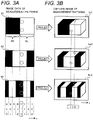
- Figs. 3A a and 3B are drawings illustrating measurement patterns in accordance with a spatial coding scheme.
- the camera 4 and the infrared light projector 3 are arranged side by side such that their respective optical axes are parallel to each other.
- the direction of these optical axes is defined as a z direction as shown in Fig. 2 .
- a direction that is orthogonal to the z direction and along which the camera 4 and the infrared light projector 3 are aligned each other is defined as an x direction.
- a direction orthogonal to the z and x directions is a y direction.
- Fig. 2 shows infrared light emitted from the infrared light projector 3 being reflected at a certain point (a luminous point) of an object and light reflected from the luminous point being incident on the camera 4.
- a parallax ⁇ is formed by lines extending from the camera 4 and the infrared light projector 3. Capturing an image projected from the infrared light projector 3 with the camera 4 causes the projected image to appear on the image captured with the camera 4 at a displacement of the parallax ⁇ .
- an x coordinate of the luminous point of the object on the image captured with the camera 4 varies with distance to the luminous point, as shown in Fig. 2 .
- the controller 5 determines distance in the z direction based on the coordinate variation described above by using a trigonometric approach in which the interval between the camera 4 and the infrared light projector 3 is taken as a base length.
- the base length is obtained in advance through calibration at the time of installation of the projection system 1 or other events, for example.
- the coordinate variation is determined using measurement patterns in accordance with the spatial coding scheme. A method of this determination will now be described with reference to Figs. 3A and 3B .
- Fig. 3A illustrates image data indicating a set of measurement patterns 81, 82, and 83 projected from the infrared light projector 3.
- the measurement patterns 81 to 83 each include at least one bright region R1 and at least one dark region R0 that are arranged along a direction of the x coordinate subject to determination of variation.
- the bright region R1 is greater in light amount than the dark region R0.
- "1" and "0" are assigned to the bright region R1 and the dark region R0, respectively, such that the x coordinate on image data is coded.
- the measurement pattern 81 corresponding to a first step, the measurement pattern 82 corresponding to a second step, and the measurement pattern 83 corresponding to a third step are sequentially projected.
- the three measurement patterns 81 to 83 projected in order of the first to third steps as time elapses generate 3-bit codes that correspond to eight regions on the image data.
- Fig. 3B illustrates capture images Im1, Im2, and Im3 that are each generated when the camera 4 captures the object on which a corresponding one of the measurement patterns 81, 82, and 83 of Fig. 3A is projected.
- the x coordinate of luminous points of the object on the capture images varies with the depth dimension on the object even if the luminous points are associated with an identical code "110".
- the controller 5 determines the coordinate variation by decoding imaging data indicating the capture images Im1, Im2, and Im3 at the image generator 50.
- the controller 5 assesses every pixel in one frame of a capture image by comparing the brightness of the pixel with a predetermined threshold.
- the predetermined threshold is a reference threshold value for determining pixels in the capture image that reflect luminous points in bright regions of measurement patterns.
- the predetermined threshold is set in consideration of the amount of noise light, for example.
- the controller 5 assesses each pixel against the threshold by assigning "1" to the pixel whose brightness is determined to exceed the threshold and "0" to the pixel whose brightness is determined not to exceed the threshold.
- the controller 5 performs the processing described above on all the capture images Im1, Im2, and Im3.
- the controller 5 decodes the imaging data by compiling binary values ("0" or "1") assigned to the pixels each.
- the controller 5 determines x coordinate variation by comparing the x coordinate value shown from the decoded data with the reference x coordinate value for every pixel.
- the controller 5 can determine y coordinate variation as well in like manner with the description above, for example, by using measurement patterns that are obtained through a 90-degree rotation of the measurement patterns 81 to 83 of Fig. 3A . If a parallax is formed by lines extending from the infrared light projector 3 and the visible light projector 2 as well, the controller 5 obtains information about installation locations of the two projectors in advance and converts three-dimensional coordinates defined for the infrared light projector 3 into three-dimensional coordinates defined for the visible light projector 2 as appropriate, for example.
- two-dimensional detection is performed so as to obtain a position and the like of the marker 61 at high speed using the capture images of the measurement patterns 81 to 83 ( Fig. 3A ) for three-dimensional measurement as described above.
- the images captured with the camera 4 include some potions capturing the bright regions R1 in the measurement patterns 81 to 83 projected from the infrared light projector 3 (hereinafter, referred to as "bright portions") and other potions capturing the dark regions R0 (hereinafter, referred to as "dark portions").
- the marker 61 held by the subject 6 may be positioned in the dark region R0 during the projection of a certain measurement pattern. If it fails to obtain light reflected from the marker 61, the marker 61 would not be imaged in the camera 4. This prevents the marker 61 from being detected in the dark portions of each frame of the capture image, which makes it difficult to perform the two-dimensional detection on each frame of the capture image.
- the projection system 1 of this embodiment causes the infrared light illuminator 30 to irradiate the subject 6 holding the marker 61 with infrared light as uniform light when the infrared light projector 3 to project the measurement patterns 81 to 83 onto the subject 6.
- the infrared light illuminator 30 causes the infrared light illuminator 30 to irradiate the subject 6 holding the marker 61 with infrared light as uniform light when the infrared light projector 3 to project the measurement patterns 81 to 83 onto the subject 6.
- An alternative method for the two-dimensional detection might be performed by decoding images that result from capturing a plurality of measurement patterns, comparing coordinates obtained from the decoding results with reference coordinates to obtain three-dimensional measurement, and detecting some of contours of a generated shape as the position of the subject, for example.
- this method requires a plurality of frames of the capture image in order to detect a specific location on the subject.
- the two-dimensional detection of this embodiment allows the marker 61 to be detected in each frame of the capture image. Accordingly, the time required to obtain the position of the marker 61 can be remarkably reduced. This allows the projection system 1 to reduce the time required to project the image 71 in accordance with the position of the marker 61 on the subject 6 and perform projecting operation with reduced variation in position of the subject 6.
- FIG. 4 is a drawing illustrating the projecting operation according to this embodiment.
- the infrared light projector 3 sequentially projects each pattern in a set of the measurement patterns 81 to 83 (see Figs. 3A ) onto a range including an entire projection surface of the screen 10, the subject 6, and other regions.
- Fig. 4 illustrates one frame of a measurement pattern 8 projected from the infrared light projector 3.
- a frame rate at which the infrared light projector 3 projects images is, for example, 60 fps to 240 fps.
- the infrared light illuminator 30 uniformly irradiates a range where the measurement pattern 8 is projected with infrared light having uniform distribution 9.
- the measurement pattern 8 from the infrared light projector 3 and the uniform distribution 9 of the infrared light from the infrared light illuminator 30 are superimposed on each other within the same range to form an invisible light image (See Fig. 5C ).
- the camera 4 captures the invisible light image formed of the measurement pattern 8 and the uniform distribution 9 of the infrared light to generate a capture image 11.
- the camera 4 outputs imaging data showing the capture image 11 to the controller 5.
- the camera 4 captures an image of each frame of the measurement pattern 8 in synchronization with the operation of the infrared light projector 3 under control of the controller 5, for example.
- the controller 5 performs the three-dimensional measurement and the two-dimensional detection based on the capture image 11 shown by the imaging data.
- three-dimensional shapes including contours and asperities of the subject 6 and the like are subject to the three-dimensional measurement, for example.
- Two-dimensional coordinates indicating the position of the marker 61 on the subject 6 in the capture image 11 are subject to the two-dimensional detection.
- the image generator 50 of the controller 5 ( Fig. 1 ) generates image data including image content to be projected onto the subject 6 in accordance with the results of the three-dimensional measurement and the two-dimensional detection.
- the three-dimensional measurement is performed based on a plurality of frames of capture image 11. Specifically, in a capture image corresponding to each pattern in a set of the measurement patterns 81 to 83 ( Fig. 3B ) of the spatial coding scheme described above, the controller 5 measures a distance from each pixel to the controller 5 and generates a depth image 12 representing the distance measured for each pixel as a depth.
- the two-dimensional detection is performed on each frame of the capture image 11, for example.
- the controller 5 detects a position of a pixel having brightness more than the predetermined threshold in each frame of the capture image 11 as a position of the marker 61 on the subject 6, and obtains two-dimensional position coordinates (X, Y) in the capture image 11. Details of the two-dimensional detection will be described later.
- the image generator 50 of the controller 5 corrects the image data such that the image 71 projected onto the subject 6 is appropriately shown.
- the image data is prestored in the storage 51, for example.
- the image generator 50 three-dimensionally corrects the image 71 each time the depth image 12 is generated.
- the image generator 50 two-dimensionally corrects the image 71 on a frame-by-frame basis based on the two-dimensional coordinates sequentially obtained.
- the visible light projector 2 sequentially receives the image data from the image generator 50 of the controller 5 and projects the image 71 specified by the received image data onto the subject 6 and the screen 10 at a predetermined frame rate.
- the frame rate at which the visible light projector 2 projects images is the same as the frame rate at which the camera 4 captures images, for example.
- the two-dimensional detection of the marker 61 is performed speedily while the three-dimensional measurements of the subject 6 are obtained based on the capture image 11 of the invisible light image. This allows the image 71 projected from the visible light projector 2 to follow the motion of the subject 6 precisely.
- the camera 4 of this embodiment is provided with the visible light cut-off filter 43 that cuts off visible light components and transmits infrared light components out of light incident on the camera 4.
- This configuration allows the camera 4 to capture measurement patterns projected from the infrared light projector 3 precisely without interfering with projection of the image with visible light performed by the visible light projector 2.
- the image generator 50 may also generate image data including the image 71 to be projected onto the screen 10 and outputs the image data to the visible light projector 2.
- the storage 51 prestores information on a location and a form (orientation) of the screen 10 through calibration at the time of installation of the projection system 1 or other events, for example. With reference to the information described above, the image generator 50 corrects the image 71 to be projected onto the screen 10 at the time of projecting operation.
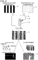
- Figs. 5A to 5E are drawings illustrating an invisible light image 80 used for the two-dimensional detection of this embodiment.
- a description will be given below of an example in which the invisible light image 80 and other images are projected onto an object having no three-dimensional distortion.
- Fig. 5A illustrates an example of the measurement patterns 8 projected from the infrared light projector 3 in the projection system 1 of this embodiment.
- Fig. 5B illustrates a distribution of the amount of light in the measurement pattern 8 in Fig. 5A.
- Fig. 5B illustrates amounts of light distributed in the x direction (this also applies to Figs. 5D and 5E ).
- a value indicating the amount of light distributed in the dark region R0 of the measurement pattern 8 projected from the infrared light projector 3, that is, a light amount value is "0".
- a light amount value of the bright region R1 is more than the light amount value of the dark region R0 by a predetermined difference B (hereinafter, referred to as "contrast difference B").
- the contrast difference B in the measurement pattern 8 is appropriately set from the viewpoint of threshold determination in the three-dimensional measurement.
- Fig. 5C illustrates an example of the invisible light images 80 according to this embodiment.
- Fig. 5D illustrates a distribution of light amounts in the invisible light image 80 of Fig. 5C.
- Fig. 5E illustrates an example of the capture image 11 corresponding to the invisible light image 80 of Fig. 5C .
- Fig. 5C illustrates the invisible light image 80 based on the measurement pattern 8 of Fig. 5A .
- the projection system 1 of this embodiment superimposes the uniform light emitted from the infrared light illuminator 30 on the measurement pattern 8 projected from the infrared light projector 3 and projects the invisible light image 80.
- the invisible light image 80 includes a pattern component and an offset component.
- the pattern component of the invisible light image 80 has the contrast difference B between the bright region R1 and the dark region R0 in accordance with the measurement pattern 8 projected from the infrared light projector 3.
- the offset component of the invisible light image 80 has an offset value b corresponding to an amount of the uniform light emitted from the infrared light illuminator 30.
- the offset value b is a predetermined positive value that is other than "0", and is set as appropriate from the viewpoint of threshold determination in the two-dimensional detection and the like.
- the light amount value of the dark region R0 is more than "0" by the offset value b. This makes it possible to receive, in the two-dimensional detection of this embodiment, reflected light having a light amount based on the offset value b from the marker 61 even if the marker 61 is positioned in the dark region R0 of the invisible light image 80 (see Fig. 5C).
- Fig. 5E illustrates a brightness distribution of the capture image 11 in such a case.
- the marker 61 retroreflects the uniform light emitted from the infrared light illuminator 30 toward the camera 4, which makes the position of the marker 61 appear brighter than regions around the marker 61 in the capture image 11.
- the capture image 11 has a brightness peak P1 corresponding to the marker 61 within a range corresponding to the dark region R0 of the invisible light image 80.
- the controller 5 of the projection system 1 obtains the position of the marker 61 such as the peak P1 by comparing brightness in the capture image 11 with a preset threshold in the two-dimensional detection.
- the threshold used for the two-dimensional detection can be set in consideration of, for example, the bright portion of the capture image 11 and brightness estimated for the marker 61 (peak PI).
- the offset value b of the invisible light image 80 for use in the projection system 1 may be set based on, for example, the contrast difference B between the bright region R1 and the dark region R0.
- the offset value b may be equal to 0.1 times the contrast difference B or another value, for example.
- such setting of the offset value b allows the brightness at the peak P1 corresponding to the marker 61 in the brightness distribution of the capture image 11 ( Fig. 5E ) to be remarkably greater than the brightness corresponding to the bright region R1.
- the offset value b may be set in consideration of, for example, brightness of noise in the brightness distribution of the capture image 11 and the like.
- the projection system 1 projects the image 71 fit for an object like the subject 6 based on the three-dimensional measurements of the object.
- the projection system 1 includes the visible light projector 2, the invisible light projector including the infrared light projector 3 and the infrared light illuminator 30, the camera 4, and the controller 5.
- the visible light projector 2 projects the image 71 onto an object with visible light.
- the invisible light projector projects the invisible light image 80 onto the object with invisible light.
- the camera 4 captures the invisible light image 80 projected from the invisible light projector.
- the controller 5 obtains, based on the capture image 11 captured with the camera 4, information regarding reflected light from the object while obtaining three-dimensional measurements of the object to control the image 71.
- the invisible light image 80 includes the bright region R1 having the predetermined light amount and the dark region R0 having the light amount less than the light amount of the bright region R1.
- the invisible light projector emits invisible light to cause the light amount of the dark region R0 in the invisible light image 80 to become equal to or more than the predetermined offset value b.
- the projection system 1 described above projects the image 71 to be fit for the object, the light amount of the dark region R0 in the invisible light image 80 to be captured becomes more than or equal to the offset value b, which enables the two-dimensional detection to be performed on the marker 61 and the like at high speed, i.e. for each frame of the capture image 11.
- This enables the projection system 1 to easily obtain information on an object such as the position of the marker 61 while obtaining three-dimensional measurements of the object.
- an object to be the subject 6 of the projection system 1 includes the marker 61 that reflects infrared light, an example of invisible light.
- the information regarding the reflected light subject to the two-dimensional detection includes a two-dimensional position of the marker 61.
- the marker 61 of this embodiment retroreflects, for example, infrared light.
- the invisible light projector of this embodiment includes the infrared light illuminator 30 as an example of illuminators.
- the infrared light illuminator 30 projects infrared light in accordance with the offset value b.
- the projection system 1 described above causes the infrared light projector 3 to project the measurement pattern 8 onto the subject 6 holding the marker 61 while causing the infrared light illuminator 30 to irradiate the subject 6 holding the marker 61 with the infrared light having the uniform distribution 9. Accordingly, regardless of the bright region R1 and the dark region R0 in the measurement pattern 8, the position of the marker 61 in the capture image 11 is captured as a region having high brightness. Setting a predetermined threshold for extraction of the region having high brightness corresponding to the position of the marker 61 enables the position of the marker 61 in the capture image 11 to be recognized.
- the projection system 1 of this embodiment is capable of detecting the position of the subject 6 at high speed while measuring the shape of the subject 6.
- the image generator 50 of the controller 5 generates image data specifying an image projected onto an object in accordance with a result of measuring the shape and position of the subject 6.
- the visible light projector 2 projects the image specified by the image data onto the object with visible light.
- the camera 4 includes the silicon-containing image pick-up device 41 and the visible light cut-off filter 43 that transmits infrared light and absorbs or reflects visible light. This configuration can prevent the camera 4 from receiving visible light even if the image pick-up device 41 has sensitivity to light in the visible spectrum.
- the camera 4 may omit the visible light cut-off filter 43 in the case of having an image pick-up device without sensitivity to light in the visible spectrum.
- the visible light cut-off filter 43 is attached to the imaging lens 42.
- the visible light cut-off filter 43 may be a filter that is built into the image pick-up device 41 or that is integrated with the imaging lens 42 in the camera 4.
- the projection system 1 of this embodiment may include the screen 10 as an example of background members.
- the screen 10 is disposed behind the subject 6 in a direction of the invisible light emitted from the invisible light projector.
- the screen 10 of this embodiment can exhibit stage effect and other effect by projecting the image 71 with visible light.
- the invisible light image 80 includes the measurement pattern 8 in accordance with the spatial coding scheme.
- the invisible light image 80 of this embodiment enables the controller 5 to obtain three-dimensional measurements of an object by decoding the bright region R1 and the dark region R0.
- the position of the marker 61 is obtained through the two-dimensional detection of the projection system 1.
- a projection system that performs two-dimensional detection to obtain, for example, contours of the subject 6 will be described with reference to Figs. 6 to 8 .
- FIG. 6 is a block diagram illustrating the configuration of the projection system 1A according to the second embodiment.
- the projection system 1A according to the second embodiment includes a screen 10A constitutes a background member that allows the contours of the subject 6 to be obtained.
- the projection system 1A of this embodiment further includes first and second polarizing filters 34 and 44 as shown in Fig. 6 .
- the projection system 1 of the first embodiment projects an invisible light image using the infrared light illuminator 30 and the infrared light projector 3.
- a description will be given of an example in which the infrared light illuminator 30 is not used in the projection system 1A. That is, in the projection system 1A of this embodiment, the infrared light projector 3 projects an invisible light image to achieve fast two-dimensional detection.
- the infrared light projector 3 of this embodiment is an example of invisible light projectors.
- the screen 10A of the second embodiment includes a reflecting surface 10a capable of preserving a polarization state.
- a projection surface of the screen 10A may be a flat surface or a curved surface as long as the projection surface is capable of preserving a polarization state.
- a silver screen having the reflecting surface 10a coated with metal powder may be used as the screen 10A of this embodiment.
- the first polarizing filter 34 is a polarizing filter that transmits only a linearly polarized component that oscillates in a specific direction out of the invisible light projected from the infrared light projector 3.
- the first polarizing filter 34 is attached to the projection optical system 33 of the infrared light projector 3, for example.
- the first polarizing filter 34 is an example of polarizers used for the infrared light projector 3 to polarize invisible light in a specific direction.
- the first polarizing filter 34 may be disposed between the infrared light source 31 in the projection optical system 33 and the screen 10 or may be integrated with the projection optical system 33.
- the second polarizing filter 44 is a polarizing filter that transmits only a linearly polarized component that oscillates in a specific direction out of light incident on the camera 4.
- the second polarizing filter 44 is installed such that polarization imparted by the second polarizing filter 44 is orthogonal to the polarization imparted by the first polarizing filter 34, which causes the second polarizing filter 44 to cut off infrared light that has been polarized by the first polarizing filter 34 in the specific direction.
- the second polarizing filter 44 is an example of polarizers that cut off a predetermined polarized component out of incident light.
- the second polarizing filter 44 is attached to the imaging lens 42, for example.
- the second polarizing filter 44 may be disposed between the image pick-up device 41 in the imaging lens 42 and the screen 10A or may be integrated with the imaging lens 42.
- the second polarizing filter 44 may be built into an image formation surface or any other part of the image pick-up device 41.
- the second polarizing filter 44 may be integrated with the visible light cut-off filter 43.
- FIG. 7 is a drawing illustrating the projecting operation of the projection system 1A according to this embodiment.
- the infrared light projector 3 projects an invisible light image 80A including a pattern component corresponding to a measurement pattern used for three-dimensional measurement and an offset component with which a projection range is uniformly irradiated that are superimposed on each other.
- the offset value b indicating the offset component of the invisible light image 80A is set in image data to be input to the infrared light projector 3 from the controller 5 ( Fig. 6 ), for example.
- the invisible light image 80A is projected from the infrared light projector 3 onto the subject 6 and the screen 10A through the first polarizing filter 34.
- the camera 4 captures, through the second polarizing filter 44, the projected invisible light image 80A.
- the screen 10A and the first and second polarizing filters 34 and 44 of this embodiment can prevent, as shown in Fig. 7 , a portion of the invisible light image 80A positioned on the screen 10A from appearing in the capture image 11 captured with the camera 4.
- the functions of the screen 10A and the filters 34 and 44 of this embodiment will be described later.
- the controller 5 performs two-dimensional detection to obtain the contours of the subject 6 while obtaining three-dimensional measurements of the subject 6 based on the capture image 11 captured with the camera 4. For example, the controller 5 recognizes, as the subject 6, pixels having high brightness greater than or equal to the predetermined threshold in the capture image 11. The controller 5 generates a mask image 13 that is a binary image in which a pixel region corresponding to the subject 6 is extracted as an object portion. Alternatively, the controller 5 may calculate, as two-dimensional coordinates of the subject 6, positions of pixels corresponding to an edge in any direction of the pixel region corresponding to the subject 6.
- the offset component included in the invisible light image 80A allows the entire image of the subject 6 to appear in all the capture images 11 captured with the camera 4, regardless of the measurement pattern used for three-dimensional measurement.
- the subject 6 appears as a region having remarkably high brightness as compared with the screen 10A, which allows a region having the predetermined threshold or greater to be recognized as the subject 6.
- a substitute image for the invisible light image 80A of this embodiment includes only the measurement pattern without superimposing of the offset component
- a dark portion in the capture image that corresponds to a captured dark region R0 of the subject 6 cannot be distinguished from the screen 10A.
- This requires extra processing such as combining a capture image of a certain measurement pattern projected from the infrared light projector 3 and another capture image of a pattern resulting from inverting the certain measurement pattern projected in the next frame, for example.
- this embodiment can remarkably shorten the time required to obtain the contours or position of the subject 6, since the region of the subject 6 and the other region can be distinguished from each other in all the capture images 11. This allows the two-dimensional detection to be performed faster, thereby allowing the image 71 projected in the projection system 1A to follow the motion of the subject 6 with a high degree of precision.
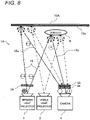
- Fig. 8 is a drawing illustrating the screen 10A and the filters 34 and 44 of the second embodiment.
- the projection system 1A of this embodiment uses the screen 10A that preserves a polarization state at the time of reflection, and the first and second polarizing filters 34 and 44 to prevent the camera 4 from receiving infrared light emitted from the infrared light projector 3 and reflected on the projection surface of the screen 10A.
- the first polarizing filter 34 transmits only a linearly polarized component that oscillates in a specific direction.
- the second polarizing filter 44 cuts off only the linearly polarized component.
- infrared light 18 emitted from the infrared light projector 3 is unpolarized light (indicated by arrows extending in all directions in Fig. 8 ).
- the first polarizing filter 34 transmits only a horizontally polarized component shown in Fig. 8 (the arrow extending in the horizontal direction).
- the infrared light 18 passed through the first polarizing filter 34 is reflected from the subject 6 or the screen 10A.
- infrared light 18a reflected on the screen 10A has its polarization state preserved on the reflecting surface 10a of the screen 10A, the infrared light 18a after the reflection has only the horizontally polarized component (the arrow extending in the horizontal direction). Then, the horizontally polarized component is cut off by the second polarizing filter 44, thereby preventing the camera 4 from receiving the infrared light reflected from the screen 10A.
- infrared light 18b reflected on the subject 6 has its polarization disturbed on the surface of the subject 6, which in turn becomes unpolarized light (arrows extending in all directions).
- the horizontally polarized component is cut off by the second polarizing filter 44, while the other polarized components pass through the second polarizing filter 44 (arrows extending in the vertical direction). Accordingly, the infrared light reflected from the subject 6 is received by the camera 4. This configuration allows the camera 4 to capture an image in which the contours of the subject 6 clearly appears.
- a predetermined polarization state of the infrared light passed through the first polarizing filter 34 may be a state where a predetermined polarized component makes up more than 50% of the invisible light.
- the predetermined polarization state of the infrared light passed through the first polarizing filter 34 may be a state where the predetermined polarized component makes up 60% or more of the invisible light.
- a silver screen may be used as the screen 10A to enable diffusion and reflection of visible light. This configuration allows the screen 10 to ensure visibility of images projected from the visible light projector 2.
- the controller 5 of the projection system 1A obtains the information regarding the reflected light from the object other than the screen 10A, such as the contours of the subject 6.
- This configuration allows the image 71 to be projected fit for the shape of an object like the subject 6 with a high degree of precision.
- the screen 10A as an example of background members reflects invisible light incident on the reflecting surface 10a with the polarization state of the invisible light being preserved.
- the screen 10A is made up of a silver screen coated with metal powder, for example.
- the infrared light projector 3 serving as the invisible light projector emits invisible light having the predetermined polarization state made by the first polarizing filter 34, for example.
- the camera 4 is provided with the second polarizing filter 44 to cut off components having the above-described polarization state out of the invisible light incident on the camera 4.
- the projection system 1A described above causes the screen 10A to reflect the invisible light emitted from the infrared light projector 3 with the polarization state being preserved, thereby causing the invisible light reflected from the screen 10A to be cut off by the second polarizing filter 44.
- This configuration enables the projection system 1 for projecting images fit for the shape or position of an object to obtain measurements of a shape of the subject 6 with a high degree of precision while detecting the position and the like of the subject 6 at high speed.
- the screen 10A diffusely reflects visible light. This configuration enables the screen 10A to show images projected from the visible light projector 2 and enhance stage effect produced by the projection system 1A.
- the projection system 1A of this embodiment is not limited to the configuration in which the infrared light projector 3 projects the invisible light image 80A including the offset component with infrared light that is invisible light, but may use the infrared light illuminator 30 of the first embodiment (see Fig. 1 ), for example.
- the infrared light illuminator 30 projects infrared light having the same polarization state as the infrared light projected from the infrared light projector 3 has with the same configuration as the first polarizing filter 34, for example.
- the first polarizing filter 34 is a filter attached to the projection optical system 33 of the infrared light projector 3.
- the first polarizing filter 34 may be integrated with the projection optical system 33 of the infrared light projector 3.
- the infrared light source 31 of the infrared light projector 3 emits light having polarization corresponding to the above-described polarization state
- the first polarizing filter 34 may be omitted.
- the infrared light source 31 includes a light emitting element such as a laser light source, for example.
- the second polarizing filter 44 is attached to the imaging lens 42 in the camera 4.
- the second polarizing filter 44 may be a filter that is built into the image pick-up device 41 or that is integrated with the imaging lens 42 in the camera 4.
- the polarization state for use in the projection system 1A of this embodiment is not limited to a specific linearly polarized component.
- the projection system 1A of this embodiment may have a configuration where the first polarizing filter 34 converts invisible light into only invisible light components having a predetermined polarization state, such as circularly polarized light or elliptically polarized light, and the second polarizing filter 44 cuts off only the invisible light components having the polarization state.
- This configuration also makes it possible to prevent invisible light having the predetermined polarization that is projected from the infrared light projector 3 and passes through the first polarizing filter 34 from being detected by the camera 4 through the second polarizing filter 44.
- the predetermined polarization state may be a state where the predetermined polarized component makes up more than 50% of or 60% or more of the invisible light.
- FIG. 9 A third embodiment will now be described with reference to the attached drawings.
- the screen 10A that diffusely reflects invisible light is used.
- a projection system using a screen that prevents invisible light from being diffusely reflected will be described with reference to Figs. 9 and 10 .
- Fig. 9 is a block diagram illustrating a configuration of a projection system 1B according to the third embodiment.
- the projection system 1B according to this embodiment includes a screen 10B, constituting a background member, which prevents infrared light from being diffusely reflected.
- the screen 10B of the third embodiment has a two-layer structure including a visible light diffusion layer 101 that diffusely reflects visible light and an infrared light cut-off layer 102 that cuts off infrared light (see Fig. 10 ).
- a reflecting surface 10b of the screen 10B is made up of the visible light diffusion layer 101 covered with the infrared light cut-off layer 102.
- a projection surface of the screen 10B may be a flat surface or a curved surface as long as the projection surface cuts off infrared light and diffusely reflects visible light.
- the visible light diffusion layer 101 of the screen 10B constitutes a projection surface that diffusely reflects visible light.
- the visible light diffusion layer 101 may be one of hanging screens of various kinds.
- the infrared light cut-off layer 102 exhibits optical properties of transmitting visible light components of incident light at an average of 50% or more and absorbing infrared light components of the incident light at an average of 50% or more.
- the infrared light cut-off layer 102 is made up of, for example, a film.
- the infrared light cut-off layer 102 causes the projection surface of the screen 10B to serve as a light cut-off surface that prevents incident infrared light from being diffusely reflected.
- the infrared light cut-off layer 102 is an example of light cut-off components for use in the screen 10B.
- the infrared light cut-off layer 102 may be made up of a panel, for example, other than the film. Alternatively, the infrared light cut-off layer 102 may be formed by means such as application of a coating to the visible light diffusion layer 101.
- Fig. 10 is a drawing illustrating the screen 10B in the projection system 1B of the third embodiment.
- the visible light projector 2 projects the image 71 onto the screen 10B as well as the subject 6 (refer to Fig. 9 ).
- visible light 17 from the visible light projector 2 needs to be diffusely reflected on the screen 10B to allow viewers or the like to visually identify the image 71 shown on the screen 10B.
- infrared light 18 from the infrared light projector 3 is as well diffusely reflected on the screen 10B, the boundary between a region of the subject 6 and the other region in measurement pattern images captured with the camera 4 will be indistinct.
- the screen 10B of this embodiment includes the infrared light cut-off layer 102 to prevent the infrared light 18 from being diffusely reflected on the projection surface of the screen 10B (see Fig. 10 ).
- the infrared light cut-off layer 102 to prevent the infrared light 18 from being diffusely reflected on the projection surface of the screen 10B (see Fig. 10 ).
- the screen 10B includes the visible light diffusion layer 101 that diffusely reflects visible light and the infrared light cut-off layer 102 that covers the visible light diffusion layer 101. As shown in Fig. 10 , the infrared light cut-off layer 102 transmits the visible light 17 so as to allow the visible light 17 to diffusely reflect on the projection surface of the screen 10B. This configuration allows the screen 10B to ensure visibility of images projected from the visible light projector 2.
- the screen 10B as an example of background members prevents invisible light incident on the reflecting surface 10b from being diffusely reflected on the reflecting surface 10b.
- This configuration also allows information such as the contours of the subject 6 to be easily obtained in the two-dimensional detection as in the second embodiment.
- the subject 6 may include a marker 61 that is the same as the marker 61 of the first embodiment.
- the projection system 1B of this embodiment is capable of obtaining a two-dimensional position of the marker 61 in the two-dimensional detection as in the first embodiment.
- the configuration similar to the configuration of the first embodiment has been described as an example of the invisible light projector according to this embodiment, but the invisible light projector of this embodiment may be the infrared light projector 3 as in the second embodiment.
- This configuration also exhibits the same effect as the effect described above.
- the marker 61 retroreflects invisible light.
- a marker that is not retroreflective may be included in an object subject to projection.
- the marker in the projection system of this embodiment may have a reflectance greater than or equal to a predetermined value such as 75%. This configuration causes the marker to appear at high brightness in the capture image and thereby exhibits the same effect as in the first embodiment.
- the invisible light images 80 and 80A include measurement patterns in accordance with the spatial encoding scheme.
- the invisible light image of this embodiment may include, for example, a measurement pattern in accordance with a phase difference contrast scheme or a random dot pattern, other than the measurement pattern in accordance with the spatial encoding scheme.
- the invisible light image may be appropriately set in accordance with the theory of obtaining three-dimensional measurements adopted for the projection system.
- the examples have been described in which the image 71 is projected onto an object like the subject 6, but an entity subject to the projection of the projection system is not particularly limited to such an object.
- the projection system of this embodiment is capable of causing the visible light projector 2 to project a visible light image which does not appear on the object, as an image fit for a measured object, based on the measurement result of the object.
- the projection system 1 causes the image 71 to follow the subject 6, for example.
- An object subject to projection in the projection system according to the present disclosure may be a stationary object, such as a building, other than a moving subject. If a stationary object is subject to projection in the projection system, the position of the object need not necessarily be measured during projecting operation.
- a projection system according to the present disclosure can find a variety of uses where an image is projected onto an object.
Description
- The present disclosure relates to a projection system that projects an image fit for a shape, a position, and the like of an object based on three-dimensional measurements of the object and the like.
- The systems and methods described in
US 2013/0215235 Al include a device that can scan the surrounding environment and construct a 3D image, map, or representation of the surrounding environment using, for example, invisible light projected into the environment. In some implementations, the device can also project into the surrounding environment one or more visible radiation pattern patterns (e.g., a virtual object, text, graphics, images, symbols, color patterns, etc.) that are based at least in part on the 3D map of the surrounding environment. - In order to provide a real-time measuring and projection apparatus capable of measuring a distance to a varying object in real time, and capable of, in particular, appropriate projection mapping to the varying object it is proposed in
JP 2017-015872 A - According to
US 2015/0015699 A1 apparatus, systems and methods are provided for illuminating objects in a projection area. The system includes a computing device, a projector and a camera. The computing device stores a digital model of an object, and illumination data having lighting parameters and a reference to the digital model. The projector, or another light source, projects structured light onto the projection area, and the camera simultaneously captures an image of the projection area. The computing device receives the captured image, determines a position and orientation of the object by comparing the digital model to the captured image, and then generates a canvas image including a region matching the determined position and orientation of the object. The projector projects the canvas image onto the projection area. A predefined portion of the object corresponding to the reference in the illumination data is thereby illuminated according to the lighting parameters. - A projection system according to
EP 3 273 685 A1 -
JP 2015-173431 A - The present disclosure provides a projection system that projects an image and that can facilitate obtaining information on the object while obtaining three-dimensional measurements of the object.
- The projection system according to the present disclosure projects an image based on a measurement of the object. The projection system is defined in
claim 1. - The projection system according the present disclosure captures the invisible light image having the light amount more than or equal to the offset value during projection of the image. This configuration enables the projection system to facilitate obtaining the information on the object while obtaining the three-dimensional measurements of the object.
-
-
Fig. 1 is a block diagram illustrating a configuration of a projection system according to a first embodiment. -
Fig. 2 is a drawing illustrating a theory of three-dimensional measurement used in the projection system. -
Figs. 3A and 3B are drawings illustrating measurement patterns in accordance with a spatial coding scheme. -
Fig. 4 is a drawing illustrating projecting operation of the projection system according to the first embodiment. -
Figs. 5A to 5E are drawings illustrating an invisible light image used for two-dimensional detection according to the first embodiment. -
Fig. 6 is a block diagram illustrating a configuration of a projection system according to a second embodiment. -
Fig. 7 is a drawing illustrating projecting operation of the projection system according to the second embodiment. -
Fig. 8 is a drawing illustrating a screen and filters of the projection system according to the second embodiment. -
Fig. 9 is a block diagram illustrating a configuration of a projection system according to a third embodiment. -
Fig. 10 is a drawing illustrating a screen of the projection system according to the third embodiment. - Embodiments will be described in detail below with appropriate reference to the drawings. However, description in more detail than is necessary may be omitted. For example, a detailed description of a well-known matter and a redundant description on substantially the same configuration may be omitted. This is to avoid the following description being unnecessarily redundant and to help those skilled in the art to easily understand the following description.
- The applicant has provided the accompanying drawings and the following description to help those skilled in the art to fully understand the present disclosure. Accordingly, the accompanying drawings and the following description should not be construed as limiting the scope of the claims.
- With reference to
Fig. 1 , a configuration of a projection system according to a first embodiment will now be described.Fig. 1 is a block diagram illustrating a configuration of aprojection system 1 according to this embodiment. - As shown in
Fig. 1 , theprojection system 1 according to this embodiment includes avisible light projector 2, aninfrared light projector 3, aninfrared light illuminator 30, acamera 4, acontroller 5, and ascreen 10. Theprojection system 1 is a projection mapping system that projects visible light images onto asubject 6 such as a person or the like for staging for example. Theprojection system 1 obtains three-dimensional measurements of thesubject 6 using theinfrared light projector 3 and thecamera 4 to allow thevisible light projector 2 to project animage 71 with visible light in response to a three-dimensional shape and other measurements of thesubject 6. - Furthermore, the
projection system 1 of this embodiment performs two-dimensional detection for successively obtaining a two-dimensional position of amarker 61 held by thesubject 6 to get theimage 71 to follow the motion of thesubject 6 with a high degree of precision. In this embodiment, theprojection system 1 uses theinfrared light illuminator 30 in addition to theinfrared light projector 3 and other components for the three-dimensional measurement described above to make the two-dimensional detection of themarker 61 faster. - The
marker 61 indicates a reference position at which theimage 71 is projected on thesubject 6. For example, themarker 61 is attached to a portion of thesubject 6 which is supposed to move fast, e.g. a limb of a person. In this embodiment, themarker 61 is made up of a reflecting component having retroreflectivity. - The
visible light projector 2 is a projector using the DLP, 3LCD, or LCOS technology, for example. The visiblelight projector 2 emits visible light based on image signals (image data) entering from thecontroller 5 so as to project theimage 71 that contains various image contents, for example. The visiblelight projector 2 is an example of visible light projectors according to this embodiment. As shown inFig. 1 , the visiblelight projector 2 includes a visiblelight source 21, a spatiallight modulator 22, and a projectionoptical system 23. - In this embodiment, the visible
light source 21 includes a plurality of luminous elements (e.g. LEDs) that emit red, green, and blue rays of light, respectively. The visiblelight source 21 may include a sole monochrome luminous element or a white color luminous element appropriately depending on a projection method adopted for the visiblelight projector 2. The luminous elements may be laser diodes, halogen or other lamps. - The spatial
light modulator 22 is made up of three spatial light modulation devices corresponding to RGB, for example. The spatial light modulation devices can be DMD or LCD chips, or other devices. The spatiallight modulator 22 need not necessarily be made up of the three spatial light modulation devices, but may be made up of a sole spatial light modulation device, for example. - The projection
optical system 23 includes a zoom lens for defining an angle of view for the visiblelight projector 2 and a focus lens for focus adjustment. - The infrared
light projector 3 is a projector using the DLP, LCD, or LCOS technology, for example. The infraredlight projector 3 projects a predetermined infrared measurement pattern described later and the like based on the image signals (image data) entering from thecontroller 5, for example. - The infrared
light projector 3 and the infraredlight illuminator 30 according to this embodiment are examples of invisible light projectors that project invisible light images with invisible light. This embodiment employs infrared light as an instance of invisible light. Instead, any invisible light, e.g. ultraviolet light, may be used, other than infrared light. As shown inFig. 1 , the infraredlight projector 3 includes an infraredlight source 31, a spatiallight modulation device 32, and a projectionoptical system 33. - The infrared
light source 31 emits infrared light having a peak wavelength of 800 nm to 900 nm, for example. The infraredlight source 31 includes a luminous element such as a laser diode. The luminous element of the infraredlight source 31 may be an LED, a lamp, or another element. - The spatial
light modulation device 32 is made up of a DMD or LCD chip, or another device. The spatiallight modulation device 32 forms an image on an image formation surface thereof based on the image signals entering from thecontroller 5 or another unit. Infrared light emitted from the infraredlight source 31 is incident on the image formation surface of the spatiallight modulation device 32 to be spatially modulated. - The projection
optical system 33 includes a zoom lens for defining an angle of view for the infraredlight projector 3 and a focus lens for focus adjustment. - The infrared
light illuminator 30 is an example of illuminators that projects infrared light as invisible light. The infraredlight illuminator 30 includes a light source such as an LED or a lamp. The infraredlight illuminator 30 emits infrared light having a peak wavelength of 800 nm to 900 nm, for example. - The infrared
light illuminator 30 and the infraredlight projector 3 are arranged to be able to irradiate an identical area with infrared light, for example. The infraredlight illuminator 30 and thecamera 4 are arranged in close proximity to each other and oriented in almost the same direction such that their respective optical axes align with each other. - The
projectors projectors optical systems light projector 3 and the visiblelight projector 2 may be integrated each other to act as a single instrument. - The
camera 4 is disposed at a position that allows capture of an image of an area onto which invisible light images are projected from the infraredlight projector 3 and another component. Thecamera 4 captures a measurement pattern that is projected onto the subject 6 with infrared light and generates an image of the captured pattern. Thecamera 4 outputs imaging data, i.e. data indicating the image of the captured pattern, to thecontroller 5. Thecamera 4 is an example of any imaging device for use in theprojection system 1. As shown inFig. 1 , thecamera 4 includes an image pick-updevice 41, animaging lens 42, and a visible light cut-off filter 43. - The image pick-up
device 41 includes a solid-state image sensing device, e.g. a CCD or CMOS image sensor made primarily from silicon. The image pick-updevice 41 has an imaging surface that contains a plurality of arranged pixel circuits for receiving light. The principal material used for the image pick-updevice 41 may be any material, such as germanium or gallium, other than silicon. - The
imaging lens 42 includes a zoom lens for defining an angle of view for thecamera 4 and a focus lens for focus adjustment. - The visible light cut-
off filter 43 is a bandpass filter or a longpass filter that transmits infrared light components and absorbs visible light components of incident light. The visible light cut-off filter 43 is attached to theimaging lens 42, for example. The visible light cut-off filter 43 is an example of any wavelength selector used for thecamera 4 to selectively transmit infrared light. - The visible light cut-
off filter 43 may be integrated with theimaging lens 42 through means such as forming a coating or a diffraction grating on theimaging lens 42. Alternatively, the visible light cut-off filter 43 may be built into an image formation surface (that is, imaging surface) or any other part of the image pick-updevice 41. The visible light cut-off filter 43 may be configured to reflect visible light components in place of or in addition to absorbing visible light components. - The
controller 5 is a controller that controls components of theprojection system 1. Thecontroller 5 includes a central processing unit (CPU) or a micro processing unit (MPU) to implement predetermined functions in collaboration with software, for example. As shown inFig. 1 , thecontroller 5 includes animage generator 50 and astorage 51. Thecontroller 5 is an example of any controller for use in theprojection system 1 according to this embodiment. - The
controller 5 reads data and programs stored in thestorage 51 and performs various arithmetic operations to implement functions of every kind. For example, thecontroller 5 implements functions required for theimage generator 50. Thecontroller 5 may control timings for acts performed by the components such as thecamera 4, the infraredlight projector 3, and the visible light projector 2 (e.g. control for synchronization between the units), as well as perform zoom control, focus control, and other control. - The
controller 5 may be a hardware circuit such as an electronic circuit specifically designed for implementing predetermined functions or a reconfigurable electronic circuit. Thecontroller 5 may include any of semiconductor integrated circuits, such as a CPU, an MPU, a graphics processing unit (GPU), a microcontroller, a digital signal processor (DSP), a field-programmable gate array (FPGA), and an application specific integrated circuit (ASIC). The functions of thecontroller 5 may be built into respective units of theprojection system 1 such as the visiblelight projector 2. - The
image generator 50 generates image data that specifies theimage 71 to be projected from the visiblelight projector 2. The image data needs to be generated such that projection of theimage 71 is allowed to follow the motion of thesubject 6. To achieve this, in this embodiment, thecontroller 5 obtains three-dimensional measurements of a shape of the subject 6 based on the imaging data sent from thecamera 4 while detecting a two-dimensional position of the subject 6 at high speed. - The
storage 51 is a storage medium for storing programs and data needed to implement functions of thecontroller 5. Thestorage 51 includes a hard disk drive (HDD) or a solid state drive (SSD), for example. Thestorage 51 may further include a dynamic random-access memory (DRAM), a static random-access memory (SRAM), or any other semiconductor device so as to store data temporarily and act as a workspace for thecontroller 5. Thestorage 51 stores image data for image content of various kinds and image data for measurement patterns described later, for example. - The
screen 10 is disposed behind the subject 6 in projecting directions of theprojectors screen 10 is an example of any background member for showing theimage 71 that constitutes a background for the subject 6 in theprojection system 1. Thescreen 10 enables projection of theimage 71 in conjunction with the motion of the subject 6 and enhances stage effect produced by projection mapping, for example. Theprojection system 1 of this embodiment may omit thescreen 10 as necessary when a background effect is not particularly required. - Operation of the
projection system 1 having the configuration described above will now be described. - This embodiment adopts spatial coding scheme-based active stereo measurement as an example of a theory of obtaining three-dimensional measurements of the
subject 6. The theory of this measurement will now be described with reference toFigs. 2 ,3A , and3B .Fig. 2 is a drawing illustrating a theory of three-dimensional measurement.Figs. 3A a and3B are drawings illustrating measurement patterns in accordance with a spatial coding scheme. - In
Fig. 2 , thecamera 4 and the infraredlight projector 3 are arranged side by side such that their respective optical axes are parallel to each other. In the following description, the direction of these optical axes is defined as a z direction as shown inFig. 2 . A direction that is orthogonal to the z direction and along which thecamera 4 and the infraredlight projector 3 are aligned each other is defined as an x direction. A direction orthogonal to the z and x directions is a y direction. -
Fig. 2 shows infrared light emitted from the infraredlight projector 3 being reflected at a certain point (a luminous point) of an object and light reflected from the luminous point being incident on thecamera 4. As shown inFig. 2 , a parallax θ is formed by lines extending from thecamera 4 and the infraredlight projector 3. Capturing an image projected from the infraredlight projector 3 with thecamera 4 causes the projected image to appear on the image captured with thecamera 4 at a displacement of the parallax θ. In other words, an x coordinate of the luminous point of the object on the image captured with thecamera 4 varies with distance to the luminous point, as shown inFig. 2 . - In the
projection system 1, thecontroller 5 determines distance in the z direction based on the coordinate variation described above by using a trigonometric approach in which the interval between thecamera 4 and the infraredlight projector 3 is taken as a base length. The base length is obtained in advance through calibration at the time of installation of theprojection system 1 or other events, for example. The coordinate variation is determined using measurement patterns in accordance with the spatial coding scheme. A method of this determination will now be described with reference toFigs. 3A and 3B . -
Fig. 3A illustrates image data indicating a set ofmeasurement patterns light projector 3. Themeasurement patterns 81 to 83 each include at least one bright region R1 and at least one dark region R0 that are arranged along a direction of the x coordinate subject to determination of variation. The bright region R1 is greater in light amount than the dark region R0. According to the spatial coding scheme, "1" and "0" are assigned to the bright region R1 and the dark region R0, respectively, such that the x coordinate on image data is coded. - In the illustration of
Fig. 3A , themeasurement pattern 81 corresponding to a first step, themeasurement pattern 82 corresponding to a second step, and themeasurement pattern 83 corresponding to a third step are sequentially projected. The threemeasurement patterns 81 to 83 projected in order of the first to third steps as time elapses generate 3-bit codes that correspond to eight regions on the image data. -
Fig. 3B illustrates capture images Im1, Im2, and Im3 that are each generated when thecamera 4 captures the object on which a corresponding one of themeasurement patterns Fig. 3A is projected. As shown inFig. 3B , the x coordinate of luminous points of the object on the capture images varies with the depth dimension on the object even if the luminous points are associated with an identical code "110". In this embodiment, thecontroller 5 determines the coordinate variation by decoding imaging data indicating the capture images Im1, Im2, and Im3 at theimage generator 50. - Specifically, the
controller 5 assesses every pixel in one frame of a capture image by comparing the brightness of the pixel with a predetermined threshold. The predetermined threshold is a reference threshold value for determining pixels in the capture image that reflect luminous points in bright regions of measurement patterns. The predetermined threshold is set in consideration of the amount of noise light, for example. Thecontroller 5 assesses each pixel against the threshold by assigning "1" to the pixel whose brightness is determined to exceed the threshold and "0" to the pixel whose brightness is determined not to exceed the threshold. - The
controller 5 performs the processing described above on all the capture images Im1, Im2, and Im3. Thecontroller 5 decodes the imaging data by compiling binary values ("0" or "1") assigned to the pixels each. - The
controller 5 determines x coordinate variation by comparing the x coordinate value shown from the decoded data with the reference x coordinate value for every pixel. Thecontroller 5 can determine y coordinate variation as well in like manner with the description above, for example, by using measurement patterns that are obtained through a 90-degree rotation of themeasurement patterns 81 to 83 ofFig. 3A . If a parallax is formed by lines extending from the infraredlight projector 3 and the visiblelight projector 2 as well, thecontroller 5 obtains information about installation locations of the two projectors in advance and converts three-dimensional coordinates defined for the infraredlight projector 3 into three-dimensional coordinates defined for the visiblelight projector 2 as appropriate, for example. - The outline of two-dimensional detection in the
projection system 1 according to this embodiment will now be described. - In this embodiment, two-dimensional detection is performed so as to obtain a position and the like of the
marker 61 at high speed using the capture images of themeasurement patterns 81 to 83 (Fig. 3A ) for three-dimensional measurement as described above. The images captured with thecamera 4 include some potions capturing the bright regions R1 in themeasurement patterns 81 to 83 projected from the infrared light projector 3 (hereinafter, referred to as "bright portions") and other potions capturing the dark regions R0 (hereinafter, referred to as "dark portions"). - In the
projection system 1, themarker 61 held by the subject 6 may be positioned in the dark region R0 during the projection of a certain measurement pattern. If it fails to obtain light reflected from themarker 61, themarker 61 would not be imaged in thecamera 4. This prevents themarker 61 from being detected in the dark portions of each frame of the capture image, which makes it difficult to perform the two-dimensional detection on each frame of the capture image. - To address this problem, the
projection system 1 of this embodiment causes the infraredlight illuminator 30 to irradiate the subject 6 holding themarker 61 with infrared light as uniform light when the infraredlight projector 3 to project themeasurement patterns 81 to 83 onto thesubject 6. As a result, light reflected from themarker 61 can be obtained regardless of themeasurement patterns 81 to 83 projected from the infraredlight projector 3, and themarker 61 can be detected in each frame of the image captured with thecamera 4. - An alternative method for the two-dimensional detection might be performed by decoding images that result from capturing a plurality of measurement patterns, comparing coordinates obtained from the decoding results with reference coordinates to obtain three-dimensional measurement, and detecting some of contours of a generated shape as the position of the subject, for example. However, this method requires a plurality of frames of the capture image in order to detect a specific location on the subject.
- In contrast to this, the two-dimensional detection of this embodiment allows the
marker 61 to be detected in each frame of the capture image. Accordingly, the time required to obtain the position of themarker 61 can be remarkably reduced. This allows theprojection system 1 to reduce the time required to project theimage 71 in accordance with the position of themarker 61 on thesubject 6 and perform projecting operation with reduced variation in position of thesubject 6. - With reference to
Figs. 1 and4 , the projecting operation of theprojection system 1 for performing projection mapping according to this embodiment will be described.Fig. 4 is a drawing illustrating the projecting operation according to this embodiment. - In this embodiment, the infrared
light projector 3 sequentially projects each pattern in a set of themeasurement patterns 81 to 83 (seeFigs. 3A ) onto a range including an entire projection surface of thescreen 10, thesubject 6, and other regions.Fig. 4 illustrates one frame of ameasurement pattern 8 projected from the infraredlight projector 3. A frame rate at which the infraredlight projector 3 projects images is, for example, 60 fps to 240 fps. - The infrared
light illuminator 30 uniformly irradiates a range where themeasurement pattern 8 is projected with infrared light havinguniform distribution 9. In this embodiment, themeasurement pattern 8 from the infraredlight projector 3 and theuniform distribution 9 of the infrared light from the infraredlight illuminator 30 are superimposed on each other within the same range to form an invisible light image (SeeFig. 5C ). - At this time, the
camera 4 captures the invisible light image formed of themeasurement pattern 8 and theuniform distribution 9 of the infrared light to generate acapture image 11. Thecamera 4 outputs imaging data showing thecapture image 11 to thecontroller 5. Thecamera 4 captures an image of each frame of themeasurement pattern 8 in synchronization with the operation of the infraredlight projector 3 under control of thecontroller 5, for example. - The
controller 5 performs the three-dimensional measurement and the two-dimensional detection based on thecapture image 11 shown by the imaging data. In this embodiment, three-dimensional shapes including contours and asperities of the subject 6 and the like are subject to the three-dimensional measurement, for example. Two-dimensional coordinates indicating the position of themarker 61 on the subject 6 in thecapture image 11 are subject to the two-dimensional detection. Theimage generator 50 of the controller 5 (Fig. 1 ) generates image data including image content to be projected onto the subject 6 in accordance with the results of the three-dimensional measurement and the two-dimensional detection. - The three-dimensional measurement is performed based on a plurality of frames of
capture image 11. Specifically, in a capture image corresponding to each pattern in a set of themeasurement patterns 81 to 83 (Fig. 3B ) of the spatial coding scheme described above, thecontroller 5 measures a distance from each pixel to thecontroller 5 and generates adepth image 12 representing the distance measured for each pixel as a depth. - On the other hand, the two-dimensional detection is performed on each frame of the
capture image 11, for example. In this embodiment, thecontroller 5 detects a position of a pixel having brightness more than the predetermined threshold in each frame of thecapture image 11 as a position of themarker 61 on thesubject 6, and obtains two-dimensional position coordinates (X, Y) in thecapture image 11. Details of the two-dimensional detection will be described later. - Based on the generated
depth image 12 and the obtained two-dimensional coordinates, theimage generator 50 of thecontroller 5 corrects the image data such that theimage 71 projected onto thesubject 6 is appropriately shown. The image data is prestored in thestorage 51, for example. For example, theimage generator 50 three-dimensionally corrects theimage 71 each time thedepth image 12 is generated. Within a period corresponding to a plurality of frames until a new depth image is obtained, theimage generator 50 two-dimensionally corrects theimage 71 on a frame-by-frame basis based on the two-dimensional coordinates sequentially obtained. - The visible
light projector 2 sequentially receives the image data from theimage generator 50 of thecontroller 5 and projects theimage 71 specified by the received image data onto thesubject 6 and thescreen 10 at a predetermined frame rate. The frame rate at which the visiblelight projector 2 projects images is the same as the frame rate at which thecamera 4 captures images, for example. - According to the above projecting operation, the two-dimensional detection of the
marker 61 is performed speedily while the three-dimensional measurements of the subject 6 are obtained based on thecapture image 11 of the invisible light image. This allows theimage 71 projected from the visiblelight projector 2 to follow the motion of the subject 6 precisely. - As shown in
Fig. 1 , thecamera 4 of this embodiment is provided with the visible light cut-off filter 43 that cuts off visible light components and transmits infrared light components out of light incident on thecamera 4. This configuration allows thecamera 4 to capture measurement patterns projected from the infraredlight projector 3 precisely without interfering with projection of the image with visible light performed by the visiblelight projector 2. - In the above projecting operation, the
image generator 50 may also generate image data including theimage 71 to be projected onto thescreen 10 and outputs the image data to the visiblelight projector 2. Thestorage 51 prestores information on a location and a form (orientation) of thescreen 10 through calibration at the time of installation of theprojection system 1 or other events, for example. With reference to the information described above, theimage generator 50 corrects theimage 71 to be projected onto thescreen 10 at the time of projecting operation. - Details of the two-dimensional detection using the invisible light image of this embodiment will be described with reference to
Figs. 5A to 5E. Figs. 5A to 5E are drawings illustrating an invisiblelight image 80 used for the two-dimensional detection of this embodiment. For the sake of simplicity, a description will be given below of an example in which the invisiblelight image 80 and other images are projected onto an object having no three-dimensional distortion. -
Fig. 5A illustrates an example of themeasurement patterns 8 projected from the infraredlight projector 3 in theprojection system 1 of this embodiment.Fig. 5B illustrates a distribution of the amount of light in themeasurement pattern 8 inFig. 5A. Fig. 5B illustrates amounts of light distributed in the x direction (this also applies toFigs. 5D and 5E ). - In this embodiment, as shown in
Figs. 5A and 5B , a value indicating the amount of light distributed in the dark region R0 of themeasurement pattern 8 projected from the infraredlight projector 3, that is, a light amount value, is "0". A light amount value of the bright region R1 is more than the light amount value of the dark region R0 by a predetermined difference B (hereinafter, referred to as "contrast difference B"). The contrast difference B in themeasurement pattern 8 is appropriately set from the viewpoint of threshold determination in the three-dimensional measurement. -
Fig. 5C illustrates an example of the invisiblelight images 80 according to this embodiment.Fig. 5D illustrates a distribution of light amounts in the invisiblelight image 80 ofFig. 5C. Fig. 5E illustrates an example of thecapture image 11 corresponding to the invisiblelight image 80 ofFig. 5C . -
Fig. 5C illustrates the invisiblelight image 80 based on themeasurement pattern 8 ofFig. 5A . Theprojection system 1 of this embodiment superimposes the uniform light emitted from the infraredlight illuminator 30 on themeasurement pattern 8 projected from the infraredlight projector 3 and projects the invisiblelight image 80. As shown inFig. 5D , the invisiblelight image 80 includes a pattern component and an offset component. - The pattern component of the invisible
light image 80 has the contrast difference B between the bright region R1 and the dark region R0 in accordance with themeasurement pattern 8 projected from the infraredlight projector 3. The offset component of the invisiblelight image 80 has an offset value b corresponding to an amount of the uniform light emitted from the infraredlight illuminator 30. The offset value b is a predetermined positive value that is other than "0", and is set as appropriate from the viewpoint of threshold determination in the two-dimensional detection and the like. - In the invisible
light image 80 as described above, as shown inFig. 5D , the light amount value of the dark region R0 is more than "0" by the offset value b. This makes it possible to receive, in the two-dimensional detection of this embodiment, reflected light having a light amount based on the offset value b from themarker 61 even if themarker 61 is positioned in the dark region R0 of the invisible light image 80 (seeFig. 5C). Fig. 5E illustrates a brightness distribution of thecapture image 11 in such a case. - In the
projection system 1 of this embodiment, themarker 61 retroreflects the uniform light emitted from the infraredlight illuminator 30 toward thecamera 4, which makes the position of themarker 61 appear brighter than regions around themarker 61 in thecapture image 11. In the example ofFig. 5E , thecapture image 11 has a brightness peak P1 corresponding to themarker 61 within a range corresponding to the dark region R0 of the invisiblelight image 80. - The
controller 5 of theprojection system 1 obtains the position of themarker 61 such as the peak P1 by comparing brightness in thecapture image 11 with a preset threshold in the two-dimensional detection. The threshold used for the two-dimensional detection can be set in consideration of, for example, the bright portion of thecapture image 11 and brightness estimated for the marker 61 (peak PI). - The offset value b of the invisible
light image 80 for use in theprojection system 1 may be set based on, for example, the contrast difference B between the bright region R1 and the dark region R0. The offset value b may be equal to 0.1 times the contrast difference B or another value, for example. For example, such setting of the offset value b allows the brightness at the peak P1 corresponding to themarker 61 in the brightness distribution of the capture image 11 (Fig. 5E ) to be remarkably greater than the brightness corresponding to the bright region R1. Further, the offset value b may be set in consideration of, for example, brightness of noise in the brightness distribution of thecapture image 11 and the like. - As described above, the
projection system 1 according to this embodiment projects theimage 71 fit for an object like the subject 6 based on the three-dimensional measurements of the object. Theprojection system 1 includes the visiblelight projector 2, the invisible light projector including the infraredlight projector 3 and the infraredlight illuminator 30, thecamera 4, and thecontroller 5. The visiblelight projector 2 projects theimage 71 onto an object with visible light. The invisible light projector projects the invisiblelight image 80 onto the object with invisible light. Thecamera 4 captures the invisiblelight image 80 projected from the invisible light projector. Thecontroller 5 obtains, based on thecapture image 11 captured with thecamera 4, information regarding reflected light from the object while obtaining three-dimensional measurements of the object to control theimage 71. The invisiblelight image 80 includes the bright region R1 having the predetermined light amount and the dark region R0 having the light amount less than the light amount of the bright region R1. The invisible light projector emits invisible light to cause the light amount of the dark region R0 in the invisiblelight image 80 to become equal to or more than the predetermined offset value b. - When the
projection system 1 described above projects theimage 71 to be fit for the object, the light amount of the dark region R0 in the invisiblelight image 80 to be captured becomes more than or equal to the offset value b, which enables the two-dimensional detection to be performed on themarker 61 and the like at high speed, i.e. for each frame of thecapture image 11. This enables theprojection system 1 to easily obtain information on an object such as the position of themarker 61 while obtaining three-dimensional measurements of the object. - Further, in the
projection system 1 of this embodiment, an object to be thesubject 6 of theprojection system 1 includes themarker 61 that reflects infrared light, an example of invisible light. The information regarding the reflected light subject to the two-dimensional detection includes a two-dimensional position of themarker 61. Themarker 61 of this embodiment retroreflects, for example, infrared light. The invisible light projector of this embodiment includes the infraredlight illuminator 30 as an example of illuminators. The infraredlight illuminator 30 projects infrared light in accordance with the offset value b. - The
projection system 1 described above causes the infraredlight projector 3 to project themeasurement pattern 8 onto the subject 6 holding themarker 61 while causing the infraredlight illuminator 30 to irradiate the subject 6 holding themarker 61 with the infrared light having theuniform distribution 9. Accordingly, regardless of the bright region R1 and the dark region R0 in themeasurement pattern 8, the position of themarker 61 in thecapture image 11 is captured as a region having high brightness. Setting a predetermined threshold for extraction of the region having high brightness corresponding to the position of themarker 61 enables the position of themarker 61 in thecapture image 11 to be recognized. - As described above, the
projection system 1 of this embodiment is capable of detecting the position of the subject 6 at high speed while measuring the shape of thesubject 6. Theimage generator 50 of thecontroller 5 generates image data specifying an image projected onto an object in accordance with a result of measuring the shape and position of thesubject 6. The visiblelight projector 2 projects the image specified by the image data onto the object with visible light. - In this embodiment, the
camera 4 includes the silicon-containing image pick-updevice 41 and the visible light cut-off filter 43 that transmits infrared light and absorbs or reflects visible light. This configuration can prevent thecamera 4 from receiving visible light even if the image pick-updevice 41 has sensitivity to light in the visible spectrum. Thecamera 4 may omit the visible light cut-off filter 43 in the case of having an image pick-up device without sensitivity to light in the visible spectrum. - In the
camera 4 according to this embodiment, the visible light cut-off filter 43 is attached to theimaging lens 42. The visible light cut-off filter 43 may be a filter that is built into the image pick-updevice 41 or that is integrated with theimaging lens 42 in thecamera 4. - The
projection system 1 of this embodiment may include thescreen 10 as an example of background members. Thescreen 10 is disposed behind the subject 6 in a direction of the invisible light emitted from the invisible light projector. Thescreen 10 of this embodiment can exhibit stage effect and other effect by projecting theimage 71 with visible light. - In this embodiment, the invisible
light image 80 includes themeasurement pattern 8 in accordance with the spatial coding scheme. The invisiblelight image 80 of this embodiment enables thecontroller 5 to obtain three-dimensional measurements of an object by decoding the bright region R1 and the dark region R0. - A second embodiment will now be described with reference to the attached drawings. In the first embodiment, the position of the
marker 61 is obtained through the two-dimensional detection of theprojection system 1. In the second embodiment, a projection system that performs two-dimensional detection to obtain, for example, contours of the subject 6 will be described with reference toFigs. 6 to 8 . - The projection system according to this embodiment will now be described. As for some configuration and operation identical to those of the
projection system 1 according to the first embodiment, redundant descriptions thereof are omitted. - With reference to
Fig. 6 , a configuration of aprojection system 1A according to the second embodiment will now be described.Fig. 6 is a block diagram illustrating the configuration of theprojection system 1A according to the second embodiment. - With the same configuration as the configuration of the first embodiment (see
Fig. 1 ), theprojection system 1A according to the second embodiment includes ascreen 10A constitutes a background member that allows the contours of the subject 6 to be obtained. Theprojection system 1A of this embodiment further includes first and secondpolarizing filters Fig. 6 . - The
projection system 1 of the first embodiment projects an invisible light image using the infraredlight illuminator 30 and the infraredlight projector 3. In this embodiment, a description will be given of an example in which the infraredlight illuminator 30 is not used in theprojection system 1A. That is, in theprojection system 1A of this embodiment, the infraredlight projector 3 projects an invisible light image to achieve fast two-dimensional detection. The infraredlight projector 3 of this embodiment is an example of invisible light projectors. - The
screen 10A of the second embodiment includes a reflectingsurface 10a capable of preserving a polarization state. A projection surface of thescreen 10A may be a flat surface or a curved surface as long as the projection surface is capable of preserving a polarization state. As thescreen 10A of this embodiment, a silver screen having the reflectingsurface 10a coated with metal powder may be used. - The first
polarizing filter 34 is a polarizing filter that transmits only a linearly polarized component that oscillates in a specific direction out of the invisible light projected from the infraredlight projector 3. The firstpolarizing filter 34 is attached to the projectionoptical system 33 of the infraredlight projector 3, for example. The firstpolarizing filter 34 is an example of polarizers used for the infraredlight projector 3 to polarize invisible light in a specific direction. The firstpolarizing filter 34 may be disposed between the infraredlight source 31 in the projectionoptical system 33 and thescreen 10 or may be integrated with the projectionoptical system 33. - The second
polarizing filter 44 is a polarizing filter that transmits only a linearly polarized component that oscillates in a specific direction out of light incident on thecamera 4. The secondpolarizing filter 44 is installed such that polarization imparted by the secondpolarizing filter 44 is orthogonal to the polarization imparted by the firstpolarizing filter 34, which causes the secondpolarizing filter 44 to cut off infrared light that has been polarized by the firstpolarizing filter 34 in the specific direction. The secondpolarizing filter 44 is an example of polarizers that cut off a predetermined polarized component out of incident light. - The second
polarizing filter 44 is attached to theimaging lens 42, for example. The secondpolarizing filter 44 may be disposed between the image pick-updevice 41 in theimaging lens 42 and thescreen 10A or may be integrated with theimaging lens 42. The secondpolarizing filter 44 may be built into an image formation surface or any other part of the image pick-updevice 41. The secondpolarizing filter 44 may be integrated with the visible light cut-off filter 43. - Operation of the
projection system 1A having the configuration described above will now be described. - With reference to
Fig. 7 , projecting operation of theprojection system 1A according to the second embodiment will be described.Fig. 7 is a drawing illustrating the projecting operation of theprojection system 1A according to this embodiment. - In the
projection system 1A of this embodiment, as shown inFig. 7 , the infraredlight projector 3 projects an invisiblelight image 80A including a pattern component corresponding to a measurement pattern used for three-dimensional measurement and an offset component with which a projection range is uniformly irradiated that are superimposed on each other. The offset value b indicating the offset component of the invisiblelight image 80A is set in image data to be input to the infraredlight projector 3 from the controller 5 (Fig. 6 ), for example. - The invisible
light image 80A is projected from the infraredlight projector 3 onto thesubject 6 and thescreen 10A through the firstpolarizing filter 34. Thecamera 4 captures, through the secondpolarizing filter 44, the projected invisiblelight image 80A. Thescreen 10A and the first and secondpolarizing filters Fig. 7 , a portion of the invisiblelight image 80A positioned on thescreen 10A from appearing in thecapture image 11 captured with thecamera 4. The functions of thescreen 10A and thefilters - In this embodiment, the
controller 5 performs two-dimensional detection to obtain the contours of the subject 6 while obtaining three-dimensional measurements of the subject 6 based on thecapture image 11 captured with thecamera 4. For example, thecontroller 5 recognizes, as thesubject 6, pixels having high brightness greater than or equal to the predetermined threshold in thecapture image 11. Thecontroller 5 generates amask image 13 that is a binary image in which a pixel region corresponding to thesubject 6 is extracted as an object portion. Alternatively, thecontroller 5 may calculate, as two-dimensional coordinates of the subject 6, positions of pixels corresponding to an edge in any direction of the pixel region corresponding to thesubject 6. - According to the above projecting operation, the offset component included in the invisible
light image 80A allows the entire image of the subject 6 to appear in all thecapture images 11 captured with thecamera 4, regardless of the measurement pattern used for three-dimensional measurement. In thecapture image 11, thesubject 6 appears as a region having remarkably high brightness as compared with thescreen 10A, which allows a region having the predetermined threshold or greater to be recognized as thesubject 6. - In the case where a substitute image for the invisible
light image 80A of this embodiment includes only the measurement pattern without superimposing of the offset component, it is conceivable that a dark portion in the capture image that corresponds to a captured dark region R0 of the subject 6 cannot be distinguished from thescreen 10A. This requires extra processing such as combining a capture image of a certain measurement pattern projected from the infraredlight projector 3 and another capture image of a pattern resulting from inverting the certain measurement pattern projected in the next frame, for example. - In contrast to the above, this embodiment can remarkably shorten the time required to obtain the contours or position of the subject 6, since the region of the subject 6 and the other region can be distinguished from each other in all the
capture images 11. This allows the two-dimensional detection to be performed faster, thereby allowing theimage 71 projected in theprojection system 1A to follow the motion of the subject 6 with a high degree of precision. - The functions of the
screen 10A and the first and secondpolarizing filters projection system 1A of this embodiment will be described with reference toFig. 8. Fig. 8 is a drawing illustrating thescreen 10A and thefilters - The
projection system 1A of this embodiment uses thescreen 10A that preserves a polarization state at the time of reflection, and the first and secondpolarizing filters camera 4 from receiving infrared light emitted from the infraredlight projector 3 and reflected on the projection surface of thescreen 10A. Specifically, when the infrared light passes through the firstpolarizing filter 34, the firstpolarizing filter 34 transmits only a linearly polarized component that oscillates in a specific direction. When the infrared light is reflected on thescreen 10A, the linearly polarized component is preserved, and when the infrared light passes through the secondpolarizing filter 44, the secondpolarizing filter 44 cuts off only the linearly polarized component. - This prevents a portion projected onto the
screen 10A out of the image projected from the infraredlight projector 3 from appearing in the capture image captured with thecamera 4. On the other hand, the other portion projected onto and reflected on the subject 6 have its polarization disturbed, which in turn becomes substantially unpolarized light. Since some of the substantially unpolarized light reflected from the subject 6 passes through the secondpolarizing filter 44, thesubject 6 appears in the capture image. This configuration makes the contours of the subject 6 distinct in the image captured with thecamera 4 and thereby enables the determination of a shape of the subject 6 with a high degree of precision. - More specifically, as shown in
Fig. 8 , for example,infrared light 18 emitted from the infraredlight projector 3 is unpolarized light (indicated by arrows extending in all directions inFig. 8 ). Next, when the emitted infrared light 18 passes through the firstpolarizing filter 34, the firstpolarizing filter 34 transmits only a horizontally polarized component shown inFig. 8 (the arrow extending in the horizontal direction). Theinfrared light 18 passed through the firstpolarizing filter 34 is reflected from the subject 6 or thescreen 10A. - Since
infrared light 18a reflected on thescreen 10A has its polarization state preserved on the reflectingsurface 10a of thescreen 10A, theinfrared light 18a after the reflection has only the horizontally polarized component (the arrow extending in the horizontal direction). Then, the horizontally polarized component is cut off by the secondpolarizing filter 44, thereby preventing thecamera 4 from receiving the infrared light reflected from thescreen 10A. On the other hand,infrared light 18b reflected on thesubject 6 has its polarization disturbed on the surface of the subject 6, which in turn becomes unpolarized light (arrows extending in all directions). In this case, the horizontally polarized component is cut off by the secondpolarizing filter 44, while the other polarized components pass through the second polarizing filter 44 (arrows extending in the vertical direction). Accordingly, the infrared light reflected from thesubject 6 is received by thecamera 4. This configuration allows thecamera 4 to capture an image in which the contours of the subject 6 clearly appears. - It is conceivable that technical difficulty arises for the first
polarizing filter 34 to convert theinfrared light 18 into light having only the horizontally polarized component. In this case, in order for the image pick-updevice 41 to discriminate between the reflection from thescreen 10A and the reflection from thesubject 6, it suffices if there is a difference between respective sum totals of polarized components of the infrared light that pass through the secondpolarizing filter 44. From this viewpoint, a predetermined polarization state of the infrared light passed through the firstpolarizing filter 34 may be a state where a predetermined polarized component makes up more than 50% of the invisible light. More preferably, in order to discriminate between the reflection off thescreen 10A and the reflection off thesubject 6, a difference greater than or equal to 10% is made to the infrared light passed through the secondpolarizing filter 44. In other words, the predetermined polarization state of the infrared light passed through the firstpolarizing filter 34 may be a state where the predetermined polarized component makes up 60% or more of the invisible light. - In this embodiment, a silver screen may be used as the
screen 10A to enable diffusion and reflection of visible light. This configuration allows thescreen 10 to ensure visibility of images projected from the visiblelight projector 2. - As described above, in this embodiment, the
controller 5 of theprojection system 1A obtains the information regarding the reflected light from the object other than thescreen 10A, such as the contours of thesubject 6. This configuration allows theimage 71 to be projected fit for the shape of an object like the subject 6 with a high degree of precision. - In the
projection system 1A of this embodiment, thescreen 10A as an example of background members reflects invisible light incident on the reflectingsurface 10a with the polarization state of the invisible light being preserved. Thescreen 10A is made up of a silver screen coated with metal powder, for example. - In the
projection system 1A of this embodiment, the infraredlight projector 3 serving as the invisible light projector emits invisible light having the predetermined polarization state made by the firstpolarizing filter 34, for example. Thecamera 4 is provided with the secondpolarizing filter 44 to cut off components having the above-described polarization state out of the invisible light incident on thecamera 4. - The
projection system 1A described above causes thescreen 10A to reflect the invisible light emitted from the infraredlight projector 3 with the polarization state being preserved, thereby causing the invisible light reflected from thescreen 10A to be cut off by the secondpolarizing filter 44. This configuration enables theprojection system 1 for projecting images fit for the shape or position of an object to obtain measurements of a shape of the subject 6 with a high degree of precision while detecting the position and the like of the subject 6 at high speed. - In this embodiment, the
screen 10A diffusely reflects visible light. This configuration enables thescreen 10A to show images projected from the visiblelight projector 2 and enhance stage effect produced by theprojection system 1A. - The
projection system 1A of this embodiment is not limited to the configuration in which the infraredlight projector 3 projects the invisiblelight image 80A including the offset component with infrared light that is invisible light, but may use the infraredlight illuminator 30 of the first embodiment (seeFig. 1 ), for example. In this configuration, the infraredlight illuminator 30 projects infrared light having the same polarization state as the infrared light projected from the infraredlight projector 3 has with the same configuration as the firstpolarizing filter 34, for example. - In this embodiment, the first
polarizing filter 34 is a filter attached to the projectionoptical system 33 of the infraredlight projector 3. The firstpolarizing filter 34 may be integrated with the projectionoptical system 33 of the infraredlight projector 3. In the case where the infraredlight source 31 of the infraredlight projector 3 emits light having polarization corresponding to the above-described polarization state, the firstpolarizing filter 34 may be omitted. In this configuration, the infraredlight source 31 includes a light emitting element such as a laser light source, for example. - In this embodiment, the second
polarizing filter 44 is attached to theimaging lens 42 in thecamera 4. The secondpolarizing filter 44 may be a filter that is built into the image pick-updevice 41 or that is integrated with theimaging lens 42 in thecamera 4. - The description has been given above of the configuration where the first
polarizing filter 34 transmits only the linearly polarized component that oscillates in the specific direction as the polarization state, and the secondpolarizing filter 44 cuts off only the linearly polarized component that oscillates in the same direction. The polarization state for use in theprojection system 1A of this embodiment is not limited to a specific linearly polarized component. - For example, the
projection system 1A of this embodiment may have a configuration where the firstpolarizing filter 34 converts invisible light into only invisible light components having a predetermined polarization state, such as circularly polarized light or elliptically polarized light, and the secondpolarizing filter 44 cuts off only the invisible light components having the polarization state. This configuration also makes it possible to prevent invisible light having the predetermined polarization that is projected from the infraredlight projector 3 and passes through the firstpolarizing filter 34 from being detected by thecamera 4 through the secondpolarizing filter 44. The predetermined polarization state may be a state where the predetermined polarized component makes up more than 50% of or 60% or more of the invisible light. - A third embodiment will now be described with reference to the attached drawings. In the second embodiment, the
screen 10A that diffusely reflects invisible light is used. In the third embodiment, a projection system using a screen that prevents invisible light from being diffusely reflected will be described with reference toFigs. 9 and10 . - The projection system according to this embodiment will now be described. As for some configuration and operation identical to those of the
respective projection systems -
Fig. 9 is a block diagram illustrating a configuration of aprojection system 1B according to the third embodiment. With the same configuration as the configuration of the first embodiment (seeFig. 1 ), theprojection system 1B according to this embodiment includes ascreen 10B, constituting a background member, which prevents infrared light from being diffusely reflected. - The
screen 10B of the third embodiment has a two-layer structure including a visiblelight diffusion layer 101 that diffusely reflects visible light and an infrared light cut-off layer 102 that cuts off infrared light (seeFig. 10 ). A reflectingsurface 10b of thescreen 10B is made up of the visiblelight diffusion layer 101 covered with the infrared light cut-off layer 102. A projection surface of thescreen 10B may be a flat surface or a curved surface as long as the projection surface cuts off infrared light and diffusely reflects visible light. - The visible
light diffusion layer 101 of thescreen 10B constitutes a projection surface that diffusely reflects visible light. The visiblelight diffusion layer 101 may be one of hanging screens of various kinds. - The infrared light cut-
off layer 102 exhibits optical properties of transmitting visible light components of incident light at an average of 50% or more and absorbing infrared light components of the incident light at an average of 50% or more. The infrared light cut-off layer 102 is made up of, for example, a film. The infrared light cut-off layer 102 causes the projection surface of thescreen 10B to serve as a light cut-off surface that prevents incident infrared light from being diffusely reflected. The infrared light cut-off layer 102 is an example of light cut-off components for use in thescreen 10B. The infrared light cut-off layer 102 may be made up of a panel, for example, other than the film. Alternatively, the infrared light cut-off layer 102 may be formed by means such as application of a coating to the visiblelight diffusion layer 101. - The function of the
screen 10B in theprojection system 1B of this embodiment will be described with reference toFig. 10. Fig. 10 is a drawing illustrating thescreen 10B in theprojection system 1B of the third embodiment. - In this embodiment, the visible
light projector 2 projects theimage 71 onto thescreen 10B as well as the subject 6 (refer toFig. 9 ). As shown inFig. 10 , visible light 17 from the visiblelight projector 2 needs to be diffusely reflected on thescreen 10B to allow viewers or the like to visually identify theimage 71 shown on thescreen 10B. Meanwhile, if infrared light 18 from the infraredlight projector 3 is as well diffusely reflected on thescreen 10B, the boundary between a region of the subject 6 and the other region in measurement pattern images captured with thecamera 4 will be indistinct. - To address this problem, the
screen 10B of this embodiment includes the infrared light cut-off layer 102 to prevent the infrared light 18 from being diffusely reflected on the projection surface of thescreen 10B (seeFig. 10 ). As a result, out of measurement patterns projected from the infraredlight projector 3, some portions projected onto thescreen 10B do not appear in a capture image with thecamera 4, but just another portion projected onto the subject 6 appear in the capture image. This configuration makes the contours of the subject 6 distinct in the image captured with thecamera 4 and thereby enables the determination of a shape and position of the subject 6 with a high degree of precision. - The
screen 10B includes the visiblelight diffusion layer 101 that diffusely reflects visible light and the infrared light cut-off layer 102 that covers the visiblelight diffusion layer 101. As shown inFig. 10 , the infrared light cut-off layer 102 transmits thevisible light 17 so as to allow thevisible light 17 to diffusely reflect on the projection surface of thescreen 10B. This configuration allows thescreen 10B to ensure visibility of images projected from the visiblelight projector 2. - As described above, in the
projection system 1B of this embodiment, thescreen 10B as an example of background members prevents invisible light incident on the reflectingsurface 10b from being diffusely reflected on the reflectingsurface 10b. This configuration also allows information such as the contours of the subject 6 to be easily obtained in the two-dimensional detection as in the second embodiment. - In the
projection system 1B of this embodiment, the subject 6 may include amarker 61 that is the same as themarker 61 of the first embodiment. Theprojection system 1B of this embodiment is capable of obtaining a two-dimensional position of themarker 61 in the two-dimensional detection as in the first embodiment. - In the above description, the configuration similar to the configuration of the first embodiment has been described as an example of the invisible light projector according to this embodiment, but the invisible light projector of this embodiment may be the infrared
light projector 3 as in the second embodiment. This configuration also exhibits the same effect as the effect described above. - The first to third embodiments described above are provided to illustrate technologies disclosed in this patent application. The technologies according to the present disclosure, however, can be applied to any variations to which change, replacement, addition, omission, or the like are appropriately made, other than the embodiments described above. A new embodiment can be made by combining some structural elements in any of the embodiments described above. In light of this, other embodiments will be exemplified.
- In the first embodiment, the
marker 61 retroreflects invisible light. In the projection system of this embodiment, a marker that is not retroreflective may be included in an object subject to projection. The marker in the projection system of this embodiment may have a reflectance greater than or equal to a predetermined value such as 75%. This configuration causes the marker to appear at high brightness in the capture image and thereby exhibits the same effect as in the first embodiment. - In the embodiments described above, the examples have been described in which the invisible
light images - In the embodiments described above, the examples have been described in which the
image 71 is projected onto an object like the subject 6, but an entity subject to the projection of the projection system is not particularly limited to such an object. For example, the projection system of this embodiment is capable of causing the visiblelight projector 2 to project a visible light image which does not appear on the object, as an image fit for a measured object, based on the measurement result of the object. - In the embodiments described above, the
projection system 1 causes theimage 71 to follow thesubject 6, for example. An object subject to projection in the projection system according to the present disclosure may be a stationary object, such as a building, other than a moving subject. If a stationary object is subject to projection in the projection system, the position of the object need not necessarily be measured during projecting operation. - The embodiments have been described above as examples of the technologies according to the present disclosure. For that purpose, the accompanying drawings and detailed description are provided.
- Consequently, the accompanying drawings and detailed description provided to illustrate the technologies described above may include structural elements that are not essential for resolving problems as well as those essential for resolving problems. Thus, it should not be immediately deemed that, merely based on the fact that the structural elements that are not essential are shown in the accompanying drawings and detailed description, the structural elements that are not essential are essential.
- Since the embodiments described above are provided to illustrate technologies according to the present disclosure, various kinds of change, replacement, addition, omission, or the like may be made to these embodiments without departing from the scope of the claims.
- A projection system according to the present disclosure can find a variety of uses where an image is projected onto an object.
Claims (11)
- A projection system (1, 1A, 1B) that projects an image (71) based on a measurement of an object (6), the projection system (1, 1A, 1B) comprising:a visible light projector (2) configured to project an image (71) with visible light;an invisible light projector (3) configured to project an invisible light image (80, 80A) onto the object (6) with invisible light;an imaging device (4) configured to capture the invisible light image projected from the invisible light projector (3);a marker (61) configured to reflect the invisible light, and adapted to be fixed to the object (6), anda controller (5) configured to obtain information regarding reflected invisible light from the object (6), configured to obtain three-dimensional measurements of the object (6) for a depth image (12) and configured to control the visible image (71), based on a capture image (11) captured with the imaging device (4), whereinthe invisible light image (80, 80A) includes a bright region (R1) having a predetermined light amount and a dark region (R0) having a light amount less than the light amount of the bright region (R1), andthe invisible light projector (3) is configured to project a set of measurement patterns, superimposed with invisible light having a uniform distribution to cause the light amount of the dark region (R0) in the invisible light image to be more than or equal to a predetermined offset value,the controller (5) is configured to generate the depth image (12) based on a plurality of frames of capture image (11) by decoding the bright region (R1) and the dark region (R0),the controller (5) is configured to detect in two dimensions the position or contour of the object (6) on each frame of capture image by detecting the pixels having a brightness more than a predetermined threshold,characterized in that the controller (5) is configured to correct the image (71) projected by the visible light projector (2) three-dimensionally each time the depth image (12) is generated, and, within a period corresponding to a plurality of frames until a new depth image (12) is obtained, two-dimensionally on a frame-by-frame basis based on the two dimensional detection, whereinthe predetermined offset value is set such that the marker (61) reflects more amount of the invisible light in the capture image (11) than other part of the object (6).
- The projection system (1, 1A, 1B) according to claim 1, wherein
the information regarding the reflected light from the object includes a two-dimensional position of the marker (61). - The projection system (1, 1A, 1B) according to claim 2, wherein the marker (61) is configured to retroreflect the invisible light.
- The projection system (1, 1A, 1B) according to any one of claims 1 to 3, wherein the invisible light projector (3) includes a light illuminator (30) configured to illuminate invisible light in accordance with the offset value.
- The projection system (1, 1A, 1B) according to any one of claims 1 to 4, further comprising a background member (10) adapted to be disposed behind the object (6) in a direction in which the invisible light projector (3) emits the invisible light.
- The projection system (1, 1A, 1B) according to claim 5, wherein the controller (5) is configured to obtain information regarding light reflected from the object (6) other than the background member (10).
- The projection system (1A, 1B) according to claim 5 or 6 further comprising a first polarizer (34) adapted to transmit only linear polarized light of the invisible light on a light path from the invisible light projector (3) to the background member (10), wherein
the background member (10) is configured to reflect invisible light incident thereon with a polarization state of the invisible light being preserved. - The projection system (1A, 1B) according to claim 7, whereinthe invisible light projector (3) is configured to emit the invisible light having a predetermined polarization state, andthe projection system further comprises a second polarizer (44) adapted to cut off a component having the predetermined polarization state out of invisible light incident on the imaging device (4).
- The projection system (1, 1A, 1B) according to claim 5 or 6, wherein the background member (10) is configured to prevent invisible light incident thereon from being diffusely reflected.
- The projection system (1, 1A, 1B) according to any one of claims 1 to 9, wherein the invisible light image (80, 80A) includes a measurement pattern in accordance with a spatial coding scheme.
- The projection system (1, 1A, 1B) according to claim 1, wherein the predetermined offset value is set such that the marker (61) reflects, at the dark region (R0), more amount of the invisible light in the capture image (11) than other part of the object (6) reflects the invisible light in the captured image, at the bright region (R1).
Applications Claiming Priority (1)
| Application Number | Priority Date | Filing Date | Title |
|---|---|---|---|
| JP2018022207A JP7236680B2 (en) | 2018-02-09 | 2018-02-09 | projection system |
Publications (2)
| Publication Number | Publication Date |
|---|---|
| EP3524929A1 EP3524929A1 (en) | 2019-08-14 |
| EP3524929B1 true EP3524929B1 (en) | 2022-05-11 |
Family
ID=65363128
Family Applications (1)
| Application Number | Title | Priority Date | Filing Date |
|---|---|---|---|
| EP19155926.9A Active EP3524929B1 (en) | 2018-02-09 | 2019-02-07 | Projection system |
Country Status (3)
| Country | Link |
|---|---|
| US (1) | US11218677B2 (en) |
| EP (1) | EP3524929B1 (en) |
| JP (1) | JP7236680B2 (en) |
Families Citing this family (6)
| Publication number | Priority date | Publication date | Assignee | Title |
|---|---|---|---|---|
| JP6822234B2 (en) * | 2017-03-15 | 2021-01-27 | セイコーエプソン株式会社 | Projector system |
| JP6782433B2 (en) * | 2017-03-22 | 2020-11-11 | パナソニックIpマネジメント株式会社 | Image recognition device |
| US10848647B1 (en) * | 2019-07-17 | 2020-11-24 | Brendan Bellomo | Composite environment filmmaking devices, systems, products and methods |
| US11867499B2 (en) * | 2020-02-19 | 2024-01-09 | Faro Technologies, Inc. | System and method for verifying a position of a component on an object |
| CN113259644B (en) * | 2021-05-17 | 2022-07-22 | 青岛海信激光显示股份有限公司 | Laser projection system and image correction method |
| JP2023023791A (en) | 2021-08-06 | 2023-02-16 | セイコーエプソン株式会社 | Display method |
Family Cites Families (18)
| Publication number | Priority date | Publication date | Assignee | Title |
|---|---|---|---|---|
| JP2575910B2 (en) | 1990-02-19 | 1997-01-29 | 株式会社 電通プロックス | Automatic tracking projector |
| JP3965088B2 (en) | 2002-07-11 | 2007-08-22 | 浜松ホトニクス株式会社 | Surface shape measuring device |
| JP4734882B2 (en) | 2004-09-29 | 2011-07-27 | カシオ計算機株式会社 | Projection apparatus, projection method, and program |
| JP4670341B2 (en) | 2004-12-22 | 2011-04-13 | パナソニック電工株式会社 | Three-dimensional shape measurement method, three-dimensional shape measurement device, and three-dimensional shape measurement program |
| JP5122729B2 (en) | 2005-04-26 | 2013-01-16 | 照明 與語 | 3D shape measurement method |
| JP2008039925A (en) | 2006-08-02 | 2008-02-21 | Dainippon Printing Co Ltd | Interactive front projection type screen system |
| US20090015548A1 (en) | 2007-06-28 | 2009-01-15 | Keiko Tazaki | Image projection system |
| JP5141110B2 (en) | 2007-06-28 | 2013-02-13 | 大日本印刷株式会社 | Image projection system |
| JP2010204572A (en) | 2009-03-05 | 2010-09-16 | Dainippon Printing Co Ltd | Reflective screen and video display system |
| JP2011002240A (en) | 2009-06-16 | 2011-01-06 | Olympus Corp | Three-dimensional shape measurement method and device |
| WO2012064520A1 (en) | 2010-11-12 | 2012-05-18 | 3M Innovative Properties Company | Interactive polarization-preserving projection display |
| WO2012064621A1 (en) * | 2010-11-12 | 2012-05-18 | 3M Innovative Properties Company | Interactive polarization-selective projection display |
| US8760499B2 (en) | 2011-04-29 | 2014-06-24 | Austin Russell | Three-dimensional imager and projection device |
| JP6104662B2 (en) | 2013-03-25 | 2017-03-29 | 株式会社東芝 | Measuring device, method and program |
| US9047514B2 (en) * | 2013-07-10 | 2015-06-02 | Christie Digital Systems Usa, Inc. | Apparatus, system and method for projecting images onto predefined portions of objects |
| JP6618249B2 (en) | 2014-02-18 | 2019-12-11 | パナソニック インテレクチュアル プロパティ コーポレーション オブ アメリカPanasonic Intellectual Property Corporation of America | Projection system and semiconductor integrated circuit |
| JP6601790B2 (en) * | 2015-06-30 | 2019-11-06 | パナソニックIpマネジメント株式会社 | Real-time measurement and projection apparatus and three-dimensional projection and measurement apparatus |
| EP3273685A1 (en) * | 2016-06-08 | 2018-01-24 | Panasonic Intellectual Property Management Co., Ltd. | Projection system |
-
2018
- 2018-02-09 JP JP2018022207A patent/JP7236680B2/en active Active
-
2019
- 2019-02-07 EP EP19155926.9A patent/EP3524929B1/en active Active
- 2019-02-08 US US16/270,740 patent/US11218677B2/en active Active
Also Published As
| Publication number | Publication date |
|---|---|
| US11218677B2 (en) | 2022-01-04 |
| US20190253679A1 (en) | 2019-08-15 |
| JP2019139069A (en) | 2019-08-22 |
| EP3524929A1 (en) | 2019-08-14 |
| JP7236680B2 (en) | 2023-03-10 |
Similar Documents
| Publication | Publication Date | Title |
|---|---|---|
| EP3524929B1 (en) | Projection system | |
| US11394939B2 (en) | Projection system | |
| US10349019B2 (en) | Projection system | |
| EP1330790B1 (en) | Accurately aligning images in digital imaging systems by matching points in the images | |
| US10728508B2 (en) | Projection system and projection method | |
| WO2017212509A1 (en) | Projection system | |
| JP6975106B2 (en) | 3D shape measurement system, 3D shape measurement method, and 3D shape measurement program | |
| US11176695B2 (en) | Shape information acquisition apparatus and shape information acquisition method |
Legal Events
| Date | Code | Title | Description |
|---|---|---|---|
| PUAI | Public reference made under article 153(3) epc to a published international application that has entered the european phase |
Free format text: ORIGINAL CODE: 0009012 |
|
| STAA | Information on the status of an ep patent application or granted ep patent |
Free format text: STATUS: THE APPLICATION HAS BEEN PUBLISHED |
|
| AK | Designated contracting states |
Kind code of ref document: A1 Designated state(s): AL AT BE BG CH CY CZ DE DK EE ES FI FR GB GR HR HU IE IS IT LI LT LU LV MC MK MT NL NO PL PT RO RS SE SI SK SM TR |
|
| AX | Request for extension of the european patent |
Extension state: BA ME |
|
| STAA | Information on the status of an ep patent application or granted ep patent |
Free format text: STATUS: REQUEST FOR EXAMINATION WAS MADE |
|
| 17P | Request for examination filed |
Effective date: 20200214 |
|
| RBV | Designated contracting states (corrected) |
Designated state(s): AL AT BE BG CH CY CZ DE DK EE ES FI FR GB GR HR HU IE IS IT LI LT LU LV MC MK MT NL NO PL PT RO RS SE SI SK SM TR |
|
| GRAP | Despatch of communication of intention to grant a patent |
Free format text: ORIGINAL CODE: EPIDOSNIGR1 |
|
| STAA | Information on the status of an ep patent application or granted ep patent |
Free format text: STATUS: GRANT OF PATENT IS INTENDED |
|
| INTG | Intention to grant announced |
Effective date: 20210804 |
|
| GRAJ | Information related to disapproval of communication of intention to grant by the applicant or resumption of examination proceedings by the epo deleted |
Free format text: ORIGINAL CODE: EPIDOSDIGR1 |
|
| STAA | Information on the status of an ep patent application or granted ep patent |
Free format text: STATUS: REQUEST FOR EXAMINATION WAS MADE |
|
| GRAP | Despatch of communication of intention to grant a patent |
Free format text: ORIGINAL CODE: EPIDOSNIGR1 |
|
| STAA | Information on the status of an ep patent application or granted ep patent |
Free format text: STATUS: GRANT OF PATENT IS INTENDED |
|
| INTC | Intention to grant announced (deleted) | ||
| INTG | Intention to grant announced |
Effective date: 20211209 |
|
| GRAS | Grant fee paid |
Free format text: ORIGINAL CODE: EPIDOSNIGR3 |
|
| GRAA | (expected) grant |
Free format text: ORIGINAL CODE: 0009210 |
|
| STAA | Information on the status of an ep patent application or granted ep patent |
Free format text: STATUS: THE PATENT HAS BEEN GRANTED |
|
| AK | Designated contracting states |
Kind code of ref document: B1 Designated state(s): AL AT BE BG CH CY CZ DE DK EE ES FI FR GB GR HR HU IE IS IT LI LT LU LV MC MK MT NL NO PL PT RO RS SE SI SK SM TR |
|
| REG | Reference to a national code |
Ref country code: GB Ref legal event code: FG4D |
|
| REG | Reference to a national code |
Ref country code: CH Ref legal event code: EP |
|
| REG | Reference to a national code |
Ref country code: AT Ref legal event code: REF Ref document number: 1491758 Country of ref document: AT Kind code of ref document: T Effective date: 20220515 |
|
| REG | Reference to a national code |
Ref country code: DE Ref legal event code: R096 Ref document number: 602019014705 Country of ref document: DE |
|
| REG | Reference to a national code |
Ref country code: IE Ref legal event code: FG4D |
|
| REG | Reference to a national code |
Ref country code: LT Ref legal event code: MG9D |
|
| REG | Reference to a national code |
Ref country code: NL Ref legal event code: MP Effective date: 20220511 |
|
| REG | Reference to a national code |
Ref country code: AT Ref legal event code: MK05 Ref document number: 1491758 Country of ref document: AT Kind code of ref document: T Effective date: 20220511 |
|
| PG25 | Lapsed in a contracting state [announced via postgrant information from national office to epo] |
Ref country code: SE Free format text: LAPSE BECAUSE OF FAILURE TO SUBMIT A TRANSLATION OF THE DESCRIPTION OR TO PAY THE FEE WITHIN THE PRESCRIBED TIME-LIMIT Effective date: 20220511 Ref country code: PT Free format text: LAPSE BECAUSE OF FAILURE TO SUBMIT A TRANSLATION OF THE DESCRIPTION OR TO PAY THE FEE WITHIN THE PRESCRIBED TIME-LIMIT Effective date: 20220912 Ref country code: NO Free format text: LAPSE BECAUSE OF FAILURE TO SUBMIT A TRANSLATION OF THE DESCRIPTION OR TO PAY THE FEE WITHIN THE PRESCRIBED TIME-LIMIT Effective date: 20220811 Ref country code: NL Free format text: LAPSE BECAUSE OF FAILURE TO SUBMIT A TRANSLATION OF THE DESCRIPTION OR TO PAY THE FEE WITHIN THE PRESCRIBED TIME-LIMIT Effective date: 20220511 Ref country code: LT Free format text: LAPSE BECAUSE OF FAILURE TO SUBMIT A TRANSLATION OF THE DESCRIPTION OR TO PAY THE FEE WITHIN THE PRESCRIBED TIME-LIMIT Effective date: 20220511 Ref country code: HR Free format text: LAPSE BECAUSE OF FAILURE TO SUBMIT A TRANSLATION OF THE DESCRIPTION OR TO PAY THE FEE WITHIN THE PRESCRIBED TIME-LIMIT Effective date: 20220511 Ref country code: GR Free format text: LAPSE BECAUSE OF FAILURE TO SUBMIT A TRANSLATION OF THE DESCRIPTION OR TO PAY THE FEE WITHIN THE PRESCRIBED TIME-LIMIT Effective date: 20220812 Ref country code: FI Free format text: LAPSE BECAUSE OF FAILURE TO SUBMIT A TRANSLATION OF THE DESCRIPTION OR TO PAY THE FEE WITHIN THE PRESCRIBED TIME-LIMIT Effective date: 20220511 Ref country code: ES Free format text: LAPSE BECAUSE OF FAILURE TO SUBMIT A TRANSLATION OF THE DESCRIPTION OR TO PAY THE FEE WITHIN THE PRESCRIBED TIME-LIMIT Effective date: 20220511 Ref country code: BG Free format text: LAPSE BECAUSE OF FAILURE TO SUBMIT A TRANSLATION OF THE DESCRIPTION OR TO PAY THE FEE WITHIN THE PRESCRIBED TIME-LIMIT Effective date: 20220811 Ref country code: AT Free format text: LAPSE BECAUSE OF FAILURE TO SUBMIT A TRANSLATION OF THE DESCRIPTION OR TO PAY THE FEE WITHIN THE PRESCRIBED TIME-LIMIT Effective date: 20220511 |
|
| PG25 | Lapsed in a contracting state [announced via postgrant information from national office to epo] |
Ref country code: RS Free format text: LAPSE BECAUSE OF FAILURE TO SUBMIT A TRANSLATION OF THE DESCRIPTION OR TO PAY THE FEE WITHIN THE PRESCRIBED TIME-LIMIT Effective date: 20220511 Ref country code: PL Free format text: LAPSE BECAUSE OF FAILURE TO SUBMIT A TRANSLATION OF THE DESCRIPTION OR TO PAY THE FEE WITHIN THE PRESCRIBED TIME-LIMIT Effective date: 20220511 Ref country code: LV Free format text: LAPSE BECAUSE OF FAILURE TO SUBMIT A TRANSLATION OF THE DESCRIPTION OR TO PAY THE FEE WITHIN THE PRESCRIBED TIME-LIMIT Effective date: 20220511 Ref country code: IS Free format text: LAPSE BECAUSE OF FAILURE TO SUBMIT A TRANSLATION OF THE DESCRIPTION OR TO PAY THE FEE WITHIN THE PRESCRIBED TIME-LIMIT Effective date: 20220911 |
|
| PG25 | Lapsed in a contracting state [announced via postgrant information from national office to epo] |
Ref country code: SM Free format text: LAPSE BECAUSE OF FAILURE TO SUBMIT A TRANSLATION OF THE DESCRIPTION OR TO PAY THE FEE WITHIN THE PRESCRIBED TIME-LIMIT Effective date: 20220511 Ref country code: SK Free format text: LAPSE BECAUSE OF FAILURE TO SUBMIT A TRANSLATION OF THE DESCRIPTION OR TO PAY THE FEE WITHIN THE PRESCRIBED TIME-LIMIT Effective date: 20220511 Ref country code: RO Free format text: LAPSE BECAUSE OF FAILURE TO SUBMIT A TRANSLATION OF THE DESCRIPTION OR TO PAY THE FEE WITHIN THE PRESCRIBED TIME-LIMIT Effective date: 20220511 Ref country code: EE Free format text: LAPSE BECAUSE OF FAILURE TO SUBMIT A TRANSLATION OF THE DESCRIPTION OR TO PAY THE FEE WITHIN THE PRESCRIBED TIME-LIMIT Effective date: 20220511 Ref country code: DK Free format text: LAPSE BECAUSE OF FAILURE TO SUBMIT A TRANSLATION OF THE DESCRIPTION OR TO PAY THE FEE WITHIN THE PRESCRIBED TIME-LIMIT Effective date: 20220511 Ref country code: CZ Free format text: LAPSE BECAUSE OF FAILURE TO SUBMIT A TRANSLATION OF THE DESCRIPTION OR TO PAY THE FEE WITHIN THE PRESCRIBED TIME-LIMIT Effective date: 20220511 |
|
| REG | Reference to a national code |
Ref country code: DE Ref legal event code: R097 Ref document number: 602019014705 Country of ref document: DE |
|
| PLBE | No opposition filed within time limit |
Free format text: ORIGINAL CODE: 0009261 |
|
| STAA | Information on the status of an ep patent application or granted ep patent |
Free format text: STATUS: NO OPPOSITION FILED WITHIN TIME LIMIT |
|
| PG25 | Lapsed in a contracting state [announced via postgrant information from national office to epo] |
Ref country code: AL Free format text: LAPSE BECAUSE OF FAILURE TO SUBMIT A TRANSLATION OF THE DESCRIPTION OR TO PAY THE FEE WITHIN THE PRESCRIBED TIME-LIMIT Effective date: 20220511 |
|
| 26N | No opposition filed |
Effective date: 20230214 |
|
| PGFP | Annual fee paid to national office [announced via postgrant information from national office to epo] |
Ref country code: FR Payment date: 20230221 Year of fee payment: 5 |
|
| PG25 | Lapsed in a contracting state [announced via postgrant information from national office to epo] |
Ref country code: SI Free format text: LAPSE BECAUSE OF FAILURE TO SUBMIT A TRANSLATION OF THE DESCRIPTION OR TO PAY THE FEE WITHIN THE PRESCRIBED TIME-LIMIT Effective date: 20220511 |
|
| PGFP | Annual fee paid to national office [announced via postgrant information from national office to epo] |
Ref country code: GB Payment date: 20230221 Year of fee payment: 5 Ref country code: DE Payment date: 20230216 Year of fee payment: 5 |
|
| PG25 | Lapsed in a contracting state [announced via postgrant information from national office to epo] |
Ref country code: MC Free format text: LAPSE BECAUSE OF FAILURE TO SUBMIT A TRANSLATION OF THE DESCRIPTION OR TO PAY THE FEE WITHIN THE PRESCRIBED TIME-LIMIT Effective date: 20220511 |
|
| REG | Reference to a national code |
Ref country code: CH Ref legal event code: PL |
|
| REG | Reference to a national code |
Ref country code: BE Ref legal event code: MM Effective date: 20230228 |
|
| PG25 | Lapsed in a contracting state [announced via postgrant information from national office to epo] |
Ref country code: LU Free format text: LAPSE BECAUSE OF NON-PAYMENT OF DUE FEES Effective date: 20230207 Ref country code: LI Free format text: LAPSE BECAUSE OF NON-PAYMENT OF DUE FEES Effective date: 20230228 Ref country code: CH Free format text: LAPSE BECAUSE OF NON-PAYMENT OF DUE FEES Effective date: 20230228 |
|
| REG | Reference to a national code |
Ref country code: IE Ref legal event code: MM4A |
|
| PG25 | Lapsed in a contracting state [announced via postgrant information from national office to epo] |
Ref country code: IT Free format text: LAPSE BECAUSE OF FAILURE TO SUBMIT A TRANSLATION OF THE DESCRIPTION OR TO PAY THE FEE WITHIN THE PRESCRIBED TIME-LIMIT Effective date: 20220511 Ref country code: IE Free format text: LAPSE BECAUSE OF NON-PAYMENT OF DUE FEES Effective date: 20230207 |
|
| PG25 | Lapsed in a contracting state [announced via postgrant information from national office to epo] |
Ref country code: BE Free format text: LAPSE BECAUSE OF NON-PAYMENT OF DUE FEES Effective date: 20230228 |