US8912708B2 - Electromechanical motor - Google Patents
Electromechanical motor Download PDFInfo
- Publication number
- US8912708B2 US8912708B2 US13/379,415 US200913379415A US8912708B2 US 8912708 B2 US8912708 B2 US 8912708B2 US 200913379415 A US200913379415 A US 200913379415A US 8912708 B2 US8912708 B2 US 8912708B2
- Authority
- US
- United States
- Prior art keywords
- actuator
- interaction portion
- interaction
- electromechanical
- driving direction
- Prior art date
- Legal status (The legal status is an assumption and is not a legal conclusion. Google has not performed a legal analysis and makes no representation as to the accuracy of the status listed.)
- Expired - Fee Related, expires
Links
Images


Classifications
-
- H—ELECTRICITY
- H02—GENERATION; CONVERSION OR DISTRIBUTION OF ELECTRIC POWER
- H02N—ELECTRIC MACHINES NOT OTHERWISE PROVIDED FOR
- H02N2/00—Electric machines in general using piezoelectric effect, electrostriction or magnetostriction
- H02N2/02—Electric machines in general using piezoelectric effect, electrostriction or magnetostriction producing linear motion, e.g. actuators; Linear positioners ; Linear motors
- H02N2/04—Constructional details
- H02N2/043—Mechanical transmission means, e.g. for stroke amplification
-
- H01L41/0913—
-
- H—ELECTRICITY
- H02—GENERATION; CONVERSION OR DISTRIBUTION OF ELECTRIC POWER
- H02N—ELECTRIC MACHINES NOT OTHERWISE PROVIDED FOR
- H02N2/00—Electric machines in general using piezoelectric effect, electrostriction or magnetostriction
-
- H—ELECTRICITY
- H02—GENERATION; CONVERSION OR DISTRIBUTION OF ELECTRIC POWER
- H02N—ELECTRIC MACHINES NOT OTHERWISE PROVIDED FOR
- H02N2/00—Electric machines in general using piezoelectric effect, electrostriction or magnetostriction
- H02N2/02—Electric machines in general using piezoelectric effect, electrostriction or magnetostriction producing linear motion, e.g. actuators; Linear positioners ; Linear motors
- H02N2/021—Electric machines in general using piezoelectric effect, electrostriction or magnetostriction producing linear motion, e.g. actuators; Linear positioners ; Linear motors using intermittent driving, e.g. step motors, piezoleg motors
-
- H—ELECTRICITY
- H02—GENERATION; CONVERSION OR DISTRIBUTION OF ELECTRIC POWER
- H02N—ELECTRIC MACHINES NOT OTHERWISE PROVIDED FOR
- H02N2/00—Electric machines in general using piezoelectric effect, electrostriction or magnetostriction
- H02N2/02—Electric machines in general using piezoelectric effect, electrostriction or magnetostriction producing linear motion, e.g. actuators; Linear positioners ; Linear motors
- H02N2/04—Constructional details
-
- H—ELECTRICITY
- H02—GENERATION; CONVERSION OR DISTRIBUTION OF ELECTRIC POWER
- H02N—ELECTRIC MACHINES NOT OTHERWISE PROVIDED FOR
- H02N2/00—Electric machines in general using piezoelectric effect, electrostriction or magnetostriction
- H02N2/02—Electric machines in general using piezoelectric effect, electrostriction or magnetostriction producing linear motion, e.g. actuators; Linear positioners ; Linear motors
- H02N2/06—Drive circuits; Control arrangements or methods
- H02N2/062—Small signal circuits; Means for controlling position or derived quantities, e.g. for removing hysteresis
-
- H—ELECTRICITY
- H10—SEMICONDUCTOR DEVICES; ELECTRIC SOLID-STATE DEVICES NOT OTHERWISE PROVIDED FOR
- H10N—ELECTRIC SOLID-STATE DEVICES NOT OTHERWISE PROVIDED FOR
- H10N30/00—Piezoelectric or electrostrictive devices
- H10N30/20—Piezoelectric or electrostrictive devices with electrical input and mechanical output, e.g. functioning as actuators or vibrators
- H10N30/202—Piezoelectric or electrostrictive devices with electrical input and mechanical output, e.g. functioning as actuators or vibrators using longitudinal or thickness displacement combined with bending, shear or torsion displacement
- H10N30/2023—Piezoelectric or electrostrictive devices with electrical input and mechanical output, e.g. functioning as actuators or vibrators using longitudinal or thickness displacement combined with bending, shear or torsion displacement having polygonal or rectangular shape
-
- H—ELECTRICITY
- H10—SEMICONDUCTOR DEVICES; ELECTRIC SOLID-STATE DEVICES NOT OTHERWISE PROVIDED FOR
- H10N—ELECTRIC SOLID-STATE DEVICES NOT OTHERWISE PROVIDED FOR
- H10N30/00—Piezoelectric or electrostrictive devices
- H10N30/20—Piezoelectric or electrostrictive devices with electrical input and mechanical output, e.g. functioning as actuators or vibrators
- H10N30/204—Piezoelectric or electrostrictive devices with electrical input and mechanical output, e.g. functioning as actuators or vibrators using bending displacement, e.g. unimorph, bimorph or multimorph cantilever or membrane benders
- H10N30/2041—Beam type
- H10N30/2042—Cantilevers, i.e. having one fixed end
-
- H01L41/094—
Definitions
- the present invention relates to electromechanical actuator devices and methods for driving such devices.
- Devices of this kind are generally based on a relatively complex motion pattern of the used actuators. This requires that several different voltage signals are provided with well defined phase shifts and/or voltage curve shapes. Furthermore, the complex driving pattern also requests large electromechanically activatable volumes producing heat during operation. The deformation of the actuators during operation also induce different kinds of material stress, which eventually may lead to cracking of electrodes, terminations and/or the electromechanically active material itself.
- An object of the present invention is to provide low complexity miniaturized motors of reasonable speed, high durability while still presenting high-accurate positioning.
- an electromechanical motor comprises an actuator assembly and a body, relative to which the actuator assembly is to be acting for causing a relative displacement of the body in a driving direction.
- the actuator assembly has an actuator backing, a first actuator and a second actuator.
- the first actuator is mechanically attached by a single attachment.
- the single attachment of the first actuator is a first attachment to the actuator backing.
- the first attachment is provided at a first end of the first actuator.
- the first actuator has a first interaction portion constituting a second end of the first actuator.
- the second end of the first actuator is opposite to the first end of the first actuator in an actuator direction.
- the second actuator is arranged in an analogue manner with a second attachment and a second interaction portion.
- the actuator direction is transverse to the driving direction.
- the first interaction portion and the second interaction portion are arranged for interaction with an interaction surface of the body by a respective contact area.
- the first actuator and said second actuator comprise a respective unimorph member comprising an electromechanical material arranged between a respective first end and a respective second end of the first actuator and the second actuator.
- Each of the unimorph members is arranged for causing a movement of a respective contact area as a response of a respective electrical signal.
- the respective movements are transverse to the actuator direction, transverse to the driving direction, as well as transverse to each other.
- an electromechanical motor system comprises an electromechanical motor according to the first aspect and a power supply, connected to the electromechanical motor and arranged for providing at least two non-identical electrical signals for excitation of the unimorph members.
- a method for driving an electromechanical motor having a first interaction portion and a second interaction portion arranged for interacting with a body comprises the step of providing of a first electrical signal for exciting a unimorph member comprising an electromechanical material attached to the first interaction portion and providing of a second electrical signal for exciting a unimorph member comprising an electromechanical material attached to the second interaction portion.
- the first electrical signal is different from the second electrical signal.
- the first electrical signal causes the unimorph member of the first interaction portion to move a contact area of the first interaction portion in a first movement direction transverse but not perpendicular to a driving direction.
- the driving direction is an intended forward travel direction of the body relative to the first interaction portion and the second interaction portion.
- the second electrical signal causes the unimorph member of the second interaction portion to move a contact area of the second interaction portion in a second movement direction transverse the driving direction.
- the second movement direction is transverse to the first movement direction.
- the first electrical signal and the second electrical are arranged for causing at least one of the first interaction portion and the second interaction portion to be in contact with the body during driving.
- One advantage with the present invention is that a stepping motion can be achieved by much less complex actuator configurations, and at the same time allow for high speed and long durability.
- FIG. 1 is a schematic side view of an embodiment of an electromechanical motor system according to the present invention
- FIGS. 2A-D are schematic illustrations of an embodiment of a ciliary motion
- FIGS. 3A-D are diagrams showing embodiments of voltage signals for achieving a ciliary motion
- FIG. 4 is a schematic side view of another embodiment of an electromechanical motor according to the present invention.
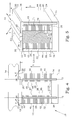
- FIGS. 5 , 6 A and 6 B are schematic perspective views of further other embodiment of actuator assemblies according to the present invention.
- FIG. 7 is a flow diagram of steps of an embodiment of a method according to the present invention.
- FIGS. 8 and 9 are schematic side views of further other embodiment of electromechanical motors according to the present invention.
- transverse is used in its ordinary wide meaning of lying in a cross-wise direction, i.e. something that crosses something else, not necessarily in a perpendicular fashion. In most cases the term can be assumed as a synonym of “non-parallel”.
- a set of one-dimensionally moving actuators can with a free end act on a body for achieving a relative moving action.
- This type of driving mechanism is sometimes referred to as a ciliary motion mechanism due to the similarities to cilia systems in the nature.
- the one-dimensional motion is typically somewhat inclined with respect to the driving direction, in order to provide also a normal force against the surface to be driven.
- Ciliary motion may be utilized either in a resonant manner or as a stepping mechanism.
- micromechanical system using ciliary motions there are many examples of micromechanical system using ciliary motions.
- Fabrication and Operation of Polyimide Bimorph Actuators for a Ciliary Motion System by M Ataka et, el. in Journal of Microelectromechanical systems, vol. 2, No. 4, December 1993, a micromotion system based on ciliary motion of bimorph thermal actuators is disclosed.
- a linear actuator based on cilia vibration by T. Hatsuzawa in Sensors and Actuators A 105 (2003) pp. 183-189
- cilia fibres are excited by external vibrators.
- most such systems have a limited positioning accuracy.
- the ciliary motion is suitable to be implemented by electromechanical actuators, e.g. piezoelectric actuators.
- electromechanical actuators e.g. piezoelectric actuators.
- By having actuators mechanically attached by a single attachment to a backing provides for a firm base.
- By having the actuators freely movable except for that single attachment and the interaction with the body to be moved creates possibilities to use dimensional changes in electromechanically active volumes of the actuators for creating the requested motion. Since the dimensional changes are essentially immediate and repeatable, very accurate motion patterns can be achieved.
- a number of advantages can be achieved.
- the driving of a unimorph actuator requires only one voltage signal, which means that the complexity in the electronic control is very low.
- the operation of a unimorph generates a smaller amount of heat compared to a similar bimorph or multimorph structure. This in turn means that the speed can be increased without risking overheating.
- the unimorph is also efficient to translate a small dimension change of an active volume into a large displacement of the end of the unimorph. At the same time, the unimorph withstands high forces along the actuator, which allows for applying high normal forces.
- Some actuator systems based on a ciliary motion are only capable of providing motion in one direction. This is typically cause by the fact that most driving systems utilize pushing or pressing forces against the body to be moved. Arrangements for other types of forces are typically complex to achieve. In order to achieve a possibility to move an object both forwards and backwards, utilizing ciliary motion, at least two actuators with transverse intended motion directions are requested.
- FIG. 1 An embodiment of an electromechanical motor 10 according to the present invention is illustrated in FIG. 1 .
- the electromechanical motor 10 comprises an actuator assembly 12 and a body 14 .
- the actuator assembly 12 is arranged to be acting on the body 14 for causing a relative displacement of the body 14 and actuator assembly 12 in a driving direction 4 .
- the actuator assembly 12 has an actuator backing 16 .
- the actuator assembly 12 of the present embodiment comprises a first actuator 20 and a second actuator 22 .
- the actuator backing 16 constitutes a support structure for the first actuator 20 and the second actuator 22 .
- the first actuator 20 is mechanically attached by a single attachment.
- This single attachment of the first actuator 20 is a first attachment 24 to the actuator backing 16 .
- the first actuator 20 has only one mechanically permanent connection to the rest of the actuator assembly 12 .
- This configuration allows the first actuator 20 to be freely movable with the first attachment 24 as a reference point.
- the first attachment 24 is provided at a first end 25 of the first actuator 20 .
- the first actuator 20 has also a first interaction portion 30 constituting a second end 31 of the first actuator 20 .
- This second end 31 of the first actuator 20 is opposite to the first end 25 of the first actuator 20 as seen in an actuator direction 5 .
- the first interaction portion 30 is arranged for interaction with an interaction surface 13 of the body 14 by a contact area 34 . This means that the firm connection to the actuator backing 16 and the contact area 34 against the body 14 are situated at two opposite ends of the first actuator 20 , leaving the first actuator without mechanical contacts between these opposite ends, i.e. between the first end 25 and the second end 31 .
- the actuator direction 5 is transverse to the driving direction 4 , and the actuator direction 5 is preferably perpendicular or substantially perpendicular to the driving direction 4 .
- the first actuator 20 comprise a unimorph member 36 comprising an electromechanical material arranged between the first end 25 and the second end 31 of the first actuator 20 , and preferably the entire distance or substantially the entire distance between the first end 25 and the second end 31 .
- the unimorph member 36 of this embodiment comprises an active volume 40 , exhibiting a change in dimension as a response of electrical signals applied to electrodes 41 electrodes imbedded into the active volume 40 .
- the unimorph member 36 of this embodiment further comprises a passive volume 44 mechanically attached to the active volume 40 along the actuator direction 5 . An interface 45 between the active volume 40 and the passive volume 44 thus extends along the entire unimorph member 36 in the actuator direction 5 .
- the active volume is typically built with electrodes in a multi-layer arrangement to reduce the driving voltage.
- the standard arrangement is to have electrodes with surfaces in the actuator direction 5 , as is shown in FIG. 1 .
- electrodes in other directions, e.g. in the driving direction 4 or the direction orthogonal to directions 4 and 5 . In these cases the d 31 coefficient gives the strain and while this coefficient is somewhat lower than the d 33 coefficient, there are still advantages such as higher fracture strength and easier fabrication.
- actuator materials could be characterised as electromechanical materials, but in the present disclosure we intend materials that change their shape when an electric voltage or current is applied.
- electromechanical materials are piezoelectric, electrostrictive and antiferroelectric materials and these materials could be single crystalline as well as polycrystalline or amorphous.
- the materials of greatest interest today are polycrystalline multilayer ferroelectric ceramic materials with large electromechanical strains, but there is an ongoing development of polymer and polymer composite materials that might result in competitive properties. Piezoelectric and electrostrictive materials are at the moment considered as the best candidates.
- the unimorph member 36 is arranged for causing a movement of the contact area 34 as a response of an electrical signal applied to the electrodes 41 .
- the active volume 40 changes typically its dimension in the actuator direction when such an electrical signal is applied, but since the active volume 40 is firmly connected to the passive volume 44 along the length of the unimorph member 36 , such dimension change instead results in a bending of the unimorph member 36 . If the dimension change is a contraction, the unimorph member 36 bends to the left (as illustrated in the FIG. 1 ), while if the dimension change is an expansion, the unimorph member 36 bends to the right. The contact area 34 will move accordingly and presents therefore a motion path along a first movement direction 6 .
- This first movement direction 6 is transverse to the actuator direction 5 as well as transverse to the driving direction 4 .
- the first movement direction 6 is furthermore non-perpendicular to the driving direction 4 , which means that the movement of the contact area 34 has a component in the driving direction 4 .
- the second actuator 22 is arranged in an analogue manner.
- the first actuator 20 and the second actuator 22 are arranged mirror symmetrically with respect to each other.
- the second actuator 22 is therefore also mechanically attached by a single attachment.
- This single attachment of the second actuator 20 is a second attachment 26 to the actuator backing 16 .
- the second attachment 26 is provided at a first end 27 of the second actuator 22 .
- the second actuator 22 has also a second interaction portion 32 constituting a second end 33 of the second actuator 22 .
- This second end 33 of the second actuator 20 is opposite to the first end 27 of the second actuator 22 as seen in the actuator direction 5 .
- the second interaction portion 32 is arranged for interaction with the interaction surface 13 of the body 14 by a contact area 35 .
- the second actuator 20 also comprise a unimorph member 38 comprising an electromechanical material arranged between the first end 27 and the second end 33 of the second actuator 22 .
- the unimorph member 38 of this embodiment comprises an active volume 42 , exhibiting a change in dimension as a response of electrical signals applied to electrodes 43 electrodes imbedded into the active volume 42 .
- the unimorph member 38 of this embodiment further comprises a passive volume 46 mechanically attached to the active volume 42 along the actuator direction 5 . An interface 47 between the active volume 42 and the passive volume 46 thus extends along the entire unimorph member 38 in the actuator direction 5 .
- the unimorph member 38 is arranged for causing a movement of the contact area 35 as a response of an electrical signal applied to the electrodes 43 . If a dimension change of the active volume 42 as a response to the applied electrical signal is a contraction, the unimorph member 38 bends to the right (as illustrated in the FIG. 1 ), while if the dimension change is an expansion, the unimorph member 38 bends to the left.
- the contact area 35 will move accordingly and presents therefore a motion path along a second movement direction 7 .
- This second movement direction 7 is transverse to the actuator direction 5 as well as transverse to the driving direction 4 .
- the second movement direction 7 is furthermore non-perpendicular to the driving direction 4 , which means that the movement of the contact area 35 has a component in the driving direction 4 .
- the active volume 40 of the first actuator 20 is positioned before the passive volume 44 in the driving direction 4
- the active volume 42 of the second actuator 22 is positioned after the passive volume 46 in the driving direction 4
- the first movement direction 6 is different from the second movement direction 7 .
- the first movement direction 6 and the second movement direction 7 are transverse to each other.
- the second movement direction 7 becomes a mirror direction of the first movement direction 6 with respect to a mirror plane parallel to the actuator direction 5 .
- the relative positions of the active and passive volumes can be the opposite, as described further below.
- an electromechanical motor system 1 comprising the electromechanical motor 10 also comprises a power supply 99 , connected to the electromechanical motor 10 and arranged for providing at least two non-identical electrical signals for excitation of the unimorph members 36 , 38 .
- FIGS. 2A-D schematically illustrates one embodiment of such a drive mechanism. Note that the dimension changes of the unimorphs are extremely exaggerated in the figure, and thereby also the bending strokes, in order to clearly illustrate the basic principles. In practice, the dimension changes and bending strokes are very small compared to the total actuator dimensions.
- both active volumes are given electrical signals causing an expansion in the actuator direction.
- This causes both actuators 20 , 22 to bend outwards from each other.
- the body 14 is in contact with both actuators 20 , 22 .
- the first actuator 20 is caused to bend back.
- the entire length of the first actuator 20 is also reduced, i.e. the contact area moves in the direction indicated by the arrow 100 .
- This releases the tip of the first actuator 20 from the body 14 , but the body 14 itself does not move, since it is supported by the second actuator 22 .
- the contraction of the active volume of the first actuator 20 is ended, the first actuator is instead bent to the left, and with a shorter length, as illustrated in FIG. 2B .
- the second actuator 22 is allowed to bend back and the contacting area of the second actuator 22 moves along the arrow 101 . Since the body 14 only is supported by the second actuator 22 , the body 14 follows in this motion and is thereby provided with a motion component in the driving direction, as illustrated by arrow 102 . We here assume that there is a normal force holding the body 14 and the actuator assembly 12 together.
- FIG. 2C When the bending of the second actuator 22 is ended, the situation as illustrated in FIG. 2C is achieved.
- the body 14 is again in contact with both actuators 20 , 22 .
- the first actuator 20 is now given electrical signals causing the unimorph of the first actuator to once more bend in the direction indicated by the arrow 103 .
- This motion also removes the contact between the second actuator 22 and the body 14 .
- the body thereby follows the first actuator 20 in its motion and is thereby given a motion component 104 in the driving direction.
- FIG. 2D is eventually reached.
- the second actuator 22 is caused to bend again for retrieving its original position from FIG. 2A , by the motion 105 .
- the situation of FIG. 2A is again achieved, however, now with the body moved a certain distance in the driving direction.
- a driving action can be achieved.
- the driving action can also be provided in the opposite direction.
- FIG. 3A two voltage curves are illustrated as an embodiment of how the driving voltages of the first and second actuator may look like.
- the upper one refers to the voltage applied over the first actuator of FIGS. 2A-D and the lower one refers to the voltage applied over the second actuator.
- a positive voltage is here assumed to cause an expansion of the active volume, and a negative voltage is assumed to cause a contraction of the active volume.
- the letters below the time axis refers to the different situation of FIGS. 2A-D .
- a single voltage curve, phase shifted 90 degrees between the two actuators can thus be used for causing a stepping action.
- a minor disadvantage with such an embodiment is that the body is only actively driven during half the period (between B and D), while is it standing still the rest of the time (between A and B and between D and A).
- FIG. 3B illustrates another embodiment of driving voltages.
- the times between the situations A-D are modified so that the periods when the body is at rest are reduced and optionally the active moving periods can be increased.
- a faster or at least smoother movement of the body is achieved.
- FIG. 3C illustrates yet another embodiment of driving voltages. These voltages cause a double ciliary motion with the actuators described before, however, in a slightly different manner as what is illustrated in FIGS. 2A-D .
- the situations of FIGS. 2B and 2D will actually not be reached.
- the operation of contracting the second actuator starts just a short while, at time E, after the contraction of the first actuator starts.
- the first actuator reaches its most contracted state at time F
- the second actuator is also almost fully contracted.
- the body will nevertheless be in contact with only the second actuator until the situation of FIG. 2C is reached.
- the first actuator starts to expand and takes over the contact to the body.
- time G also the second actuator starts to expand and when the first actuator reaches its most expanded state at time H, the second actuator is also almost fully expanded.
- the period during which the body is at rest is limited to the time between H and E of the following cycle.
- FIG. 3D illustrates another embodiment of a similar theme.
- the voltages are optimized to give a minimum resting time.
- the person skilled in the art realizes that there are numerous variations of how to apply the voltages to achieve a double ciliary motion. Even phase shifted simple wave forms, such as sinusoidal or triangular voltage curves can be used. In some such cases, the motion of the body may be somewhat strange, with parts of reciprocal motion periods, but may nevertheless be used to achieve a net motion in a pre-determined direction.
- unimorphs i.e. members having an electromechanically passive part integrated in one and the same piece as an electromechanically active part.
- the same kind of motion pattern would also be possible to achieve by more elaborate actuators, such as e.g. bimorphs, having two mechanically connected active parts.
- actuators such as e.g. bimorphs, having two mechanically connected active parts.
- unimorphs are the presently preferred building block for the ideas of the present invention.
- the use of unimorphs has certain advantages, in particular if the actuator direction is perpendicular or essentially perpendicular to the driving direction.
- the passive parts of the actuator provide a rigid support for even relatively high normal forces between the actuator assembly and the body.
- the very same members are the members causing the movement that is parallel to neither the actuator direction nor the driving direction. Further advantages of further preferred embodiments are presented here below.
- the active volumes of the actuators are facing each other, which means that the first and second movement directions 6 , 7 associated with an expansion of the active volumes are directed from each other.
- FIG. 4 the active volumes 40 , 42 of the actuators 20 , 22 are facing away from each other. This results in that the first and second movement directions 6 , 7 also are directed in mirror symmetrical directions compared with what is the situation in FIG. 1 .
- the contact areas 34 , 35 of the interaction portions 30 , 32 are provided close to the outer edge of the respective actuator 20 , 22 .
- the contact areas are situated offset in a direction along the driving direction 4 from a centre line 3 of respective actuator to 20 , 22 , to which it is attached.
- This arrangement has the advantage that an increased levering action is achieved.
- the positions at which the contact areas 34 , 35 are positioned present a larger stroke than a contact area positioned at the centre line 3 . In such a manner, the step size of each cycle can be increased, which also increases the maximum achievable speed.
- the interaction portions 30 , 32 are allowed to extend outside the main actuator cross-section.
- the first interaction portion 30 has a protruding portion 37 , protruding outside the first actuator 20 in a direction along the driving direction 4 , in this case opposite to the indicated driving direction 4 .
- the contact area 34 of the first interaction portion 30 is provided at that protruding portion 37 .
- the second interaction portion 32 has a protruding portion 39 , protruding outside the second actuator 22 in a direction along the driving direction 4 , in this case opposite to the indicated driving direction 4 .
- the contact area 35 of the second interaction portion 30 is provided at that protruding portion 39 .
- the levering action is further increased.
- the ability to withstand normal forces will be reduced, since the normal force will act outside the cross-section of the main actuator, which means that the normal force will give rise to a bending torque.
- the electrodes 41 , 43 Another feature that preferably can be utilized for further increasing the efficiency is the design of the electrodes 41 , 43 .
- the electrodes are “hidden” within the active volume in order to connect one of the electrodes, either the phase or ground electrode, with the termination electrode 29 without causing short-circuits. This is usually called an interdigital electrode arrangement.
- the problem with this is that the dimension changes in this outer in-active layer causes large tensile stresses that increase the risks for cracks at the actuator surfaces. These cracks are typically appearing at positions where terminations are provided, which may cause failure of the actuators or terminations.
- the surfaces of the passive volumes 44 , 46 can be utilized for providing terminations 29 , by which the electrodes 41 , 43 are electrically connected.
- the risk for cracks is lower, in particular in the vicinity of the middle of the passive volume 44 , 46 .
- the electrodes 41 , 43 can in many applications be allowed to extend all the way out to at least one outer surface of the active volume, and preferably to all outer surfaces.
- the electrodes can extend 41 , 43 out to at least one of a surface 51 of the active volume 40 , 42 facing away from the corresponding passive volume 44 , 46 , and a surface 50 of the active volume 40 , 42 along the driving direction 4 .
- the provision of the electrodes the entire way out to the surface of the active volume 40 , 42 has two main advantages. First, a larger volume of the electromechanically active material can be utilized for causing a motion. Secondly, any inactive layer of material outside the electrodes will counteract any shape changes of the active volume, and the reduction of such zones also makes the motion more efficient.
- the body is at least partially supported by some bearing arrangement. It is then of great importance to have the contact areas well aligned with the interaction surface 13 at the instants when both contact areas 34 , 35 are in contact with the body 14 . This occurs typically at minimum and maximum strokes. If the alignment is poor, there is a risk that only one of the contact areas 34 , 35 is in contact with the body, and the transfer of contact between the two contact areas 34 , 35 will not take place according to the intended schedule. A very accurate alignment of the interaction surface 13 of the body 14 might therefore be necessary in a general case.
- both the first actuator 20 and the second actuator 22 are provided with respective interaction portions 30 , 32 having protruding portions 37 , 39 .
- the contact area 34 of the interaction portion 30 of the first actuator 20 is here aligned with the contact area 35 of the interaction portion 32 of the second actuator 22 in the cross direction 2 . If the interaction surface 13 of the body is somewhat inclined from the intended perpendicular configuration, the same height differences will be experienced by both interaction surfaces. This in turn means that any handing-over procedures between the contact areas 34 , 35 will proceed just as planned without disturbances.
- FIG. 6B illustrates another embodiment presenting a similar alignment robust configuration of the contact areas 34 , 35 .
- the contact area 34 of the first interaction portion 30 and the contact area 35 of said second interaction portion 32 comprise respective part contact areas, being interleaved with each other in the cross direction 2 .
- FIG. 7 illustrates a flow diagram of steps of an embodiment of a method according to the present invention.
- the method for driving an electromechanical motor having a first interaction portion and a second interaction portion arranged for interacting with a body is started in step 200 .
- a first electrical signal for exciting a unimorph member attached to said first interaction portion is provided.
- a second electrical signal for exciting a unimorph member attached to said second interaction portion is provided.
- the steps 210 and 212 are performed simultaneously and in typically in cooperation.
- the first electrical signal is different from the second electrical signal.
- the first electrical signal causes in step 214 the unimorph member of the first interaction portion to move a contact area of the first interaction portion in a first movement direction transverse but not perpendicular to a driving direction.
- the driving direction is an intended forward travel direction of the body relative to the first interaction portion and the second interaction portion.
- the second electrical signal causes in step 216 the unimorph member of the second interaction portion to move a contact area of the second interaction portion in a second movement direction transverse the driving direction.
- the second movement direction is transverse also to the first movement direction.
- the first electrical signal and the second electrical are arranged for causing, in step 218 , at least one of the first interaction portion and the second interaction portion to be in contact with the body during driving. The procedure ends in step 299 .
- FIG. 8 illustrates one embodiment of an electromechanical motor having four actuators.
- the actuators are electrically connected in two pairs, thereby providing a corresponding motion scheme as described above.
- the cooperating actuators can be placed in any configuration with respect to each other, preferably selected dependent on the intended application. In the present embodiment, all four actuators are placed in a line. However, configurations of actuators provided at different two-dimensional positions are also possible. When the different groups of actuator pairs are operating out of phase with each other a smoother movement can be achieved.
- FIG. 9 illustrates an electromechanical motor having two non-parallel actuators, which furthermore are non-perpendicular to the interaction surface 13 . In this manner it is possible to use also geometrical design for determine the inclining angle between the movement directions 6 , 7 of the contact areas 34 , 35 and the driving direction 4 .
- One pair of actuators can then be used for moving the object in a first driving direction, while another pair of actuators can be used for moving the object in a transversal driving direction.
- the unimorphs are then aligned in the intended driving direction.
- FIG. 10 Another possibility to achieve a two-dimensional motion is to provide the actuators with a bimorph structure in the cross section.
- the active volume of each actuator is divided in two part active volumes in the cross direction 2 .
- the part active volumes are arranged to be excited by separate electrical signals. If the signals are different, this will result in a bending of the actuators in the cross direction 2 .
- By adapting the electrical signals a motion in a direction transverse to the driving direction can thus be allowed.
Landscapes
- General Electrical Machinery Utilizing Piezoelectricity, Electrostriction Or Magnetostriction (AREA)
- Micromachines (AREA)
Applications Claiming Priority (1)
| Application Number | Priority Date | Filing Date | Title |
|---|---|---|---|
| PCT/EP2009/057735 WO2010149199A1 (en) | 2009-06-22 | 2009-06-22 | Electromechanical motor |
Publications (2)
| Publication Number | Publication Date |
|---|---|
| US20120098468A1 US20120098468A1 (en) | 2012-04-26 |
| US8912708B2 true US8912708B2 (en) | 2014-12-16 |
Family
ID=41666431
Family Applications (1)
| Application Number | Title | Priority Date | Filing Date |
|---|---|---|---|
| US13/379,415 Expired - Fee Related US8912708B2 (en) | 2009-06-22 | 2009-06-22 | Electromechanical motor |
Country Status (4)
| Country | Link |
|---|---|
| US (1) | US8912708B2 (ja) |
| JP (1) | JP5740397B2 (ja) |
| KR (1) | KR20120112354A (ja) |
| WO (1) | WO2010149199A1 (ja) |
Families Citing this family (3)
| Publication number | Priority date | Publication date | Assignee | Title |
|---|---|---|---|---|
| DE112010006073T5 (de) * | 2010-12-20 | 2013-10-10 | Piezomotor Uppsala Ab | Elektromechanischer Motor |
| US10777730B2 (en) * | 2017-12-26 | 2020-09-15 | Santosh Kumar BEHERA | Scalable piezoelectric linear actuator |
| DE102018212897A1 (de) * | 2018-08-02 | 2020-02-06 | Zf Friedrichshafen Ag | Ziliares Verbindungselement |
Citations (17)
| Publication number | Priority date | Publication date | Assignee | Title |
|---|---|---|---|---|
| US4862030A (en) | 1986-04-07 | 1989-08-29 | Toshiba Ceramics Co., Ltd. | Piezo-electric device |
| JPH044775A (ja) | 1990-04-20 | 1992-01-09 | Toyota Central Res & Dev Lab Inc | 物体の移動装置 |
| US6307301B1 (en) * | 2000-02-02 | 2001-10-23 | The Boeing Company | Buckling resistant piezoelectric actuator |
| US6392329B1 (en) | 1999-10-12 | 2002-05-21 | Face International Corp. | Piezoelectric vibrating apparatus |
| JP2003070267A (ja) | 2001-08-23 | 2003-03-07 | Seiko Epson Corp | ワイヤーアクチュエータ |
| US20040017134A1 (en) * | 2002-07-25 | 2004-01-29 | Ganor Ze?Apos;Ev | High resolution piezoelectric motor |
| US20040074300A1 (en) * | 2000-11-23 | 2004-04-22 | Khaled Karrai | Inertial rotation device |
| US6798117B2 (en) | 2002-07-10 | 2004-09-28 | Piezomotor Uppsala Ab | Fine control of electromechanical motors |
| JP2004282819A (ja) | 2003-03-13 | 2004-10-07 | Toray Eng Co Ltd | ウォーキング動作駆動ユニットおよびそれを用いたアライメント装置 |
| JP2005033174A (ja) | 2003-06-19 | 2005-02-03 | Ngk Insulators Ltd | 筒形圧電アクチュエータ並びに筒形圧電アクチュエータアレイ及び製造方法 |
| JP2005176579A (ja) | 2003-12-15 | 2005-06-30 | Thk Co Ltd | 一軸アクチュエータ |
| US20060006764A1 (en) * | 1999-10-31 | 2006-01-12 | Nanomotion Ltd. | Piezoelectric motors and motor driving configurations |
| JP2006332616A (ja) | 2005-04-28 | 2006-12-07 | Brother Ind Ltd | 圧電アクチュエータの製造方法 |
| JP2007144251A (ja) | 2005-11-24 | 2007-06-14 | Kinsei Sangyo:Kk | 廃アスベストの溶融処理方法 |
| US20070205699A1 (en) * | 2006-03-03 | 2007-09-06 | Stefan Johansson | Heat efficient micromotor |
| WO2007144251A1 (en) | 2006-06-15 | 2007-12-21 | Piezomotor Uppsala Ab | Wide frequency range electromechanical actuator |
| US7439652B2 (en) * | 2004-02-25 | 2008-10-21 | Nanomotion Ltd. | Multidirectional piezoelectric motor configuration |
-
2009
- 2009-06-22 KR KR1020127001437A patent/KR20120112354A/ko not_active Ceased
- 2009-06-22 US US13/379,415 patent/US8912708B2/en not_active Expired - Fee Related
- 2009-06-22 WO PCT/EP2009/057735 patent/WO2010149199A1/en not_active Ceased
- 2009-06-22 JP JP2012515363A patent/JP5740397B2/ja not_active Expired - Fee Related
Patent Citations (18)
| Publication number | Priority date | Publication date | Assignee | Title |
|---|---|---|---|---|
| US4862030A (en) | 1986-04-07 | 1989-08-29 | Toshiba Ceramics Co., Ltd. | Piezo-electric device |
| JPH044775A (ja) | 1990-04-20 | 1992-01-09 | Toyota Central Res & Dev Lab Inc | 物体の移動装置 |
| US6392329B1 (en) | 1999-10-12 | 2002-05-21 | Face International Corp. | Piezoelectric vibrating apparatus |
| US20060006764A1 (en) * | 1999-10-31 | 2006-01-12 | Nanomotion Ltd. | Piezoelectric motors and motor driving configurations |
| US6307301B1 (en) * | 2000-02-02 | 2001-10-23 | The Boeing Company | Buckling resistant piezoelectric actuator |
| US20040074300A1 (en) * | 2000-11-23 | 2004-04-22 | Khaled Karrai | Inertial rotation device |
| JP2003070267A (ja) | 2001-08-23 | 2003-03-07 | Seiko Epson Corp | ワイヤーアクチュエータ |
| US6798117B2 (en) | 2002-07-10 | 2004-09-28 | Piezomotor Uppsala Ab | Fine control of electromechanical motors |
| US20040017134A1 (en) * | 2002-07-25 | 2004-01-29 | Ganor Ze?Apos;Ev | High resolution piezoelectric motor |
| JP2004282819A (ja) | 2003-03-13 | 2004-10-07 | Toray Eng Co Ltd | ウォーキング動作駆動ユニットおよびそれを用いたアライメント装置 |
| JP2005033174A (ja) | 2003-06-19 | 2005-02-03 | Ngk Insulators Ltd | 筒形圧電アクチュエータ並びに筒形圧電アクチュエータアレイ及び製造方法 |
| JP2005176579A (ja) | 2003-12-15 | 2005-06-30 | Thk Co Ltd | 一軸アクチュエータ |
| US7439652B2 (en) * | 2004-02-25 | 2008-10-21 | Nanomotion Ltd. | Multidirectional piezoelectric motor configuration |
| JP2006332616A (ja) | 2005-04-28 | 2006-12-07 | Brother Ind Ltd | 圧電アクチュエータの製造方法 |
| JP2007144251A (ja) | 2005-11-24 | 2007-06-14 | Kinsei Sangyo:Kk | 廃アスベストの溶融処理方法 |
| US20070205699A1 (en) * | 2006-03-03 | 2007-09-06 | Stefan Johansson | Heat efficient micromotor |
| WO2007144251A1 (en) | 2006-06-15 | 2007-12-21 | Piezomotor Uppsala Ab | Wide frequency range electromechanical actuator |
| US7355325B2 (en) * | 2006-06-15 | 2008-04-08 | Piezomotor Uppsala Ab | Wide frequency range electromechanical actuator |
Non-Patent Citations (3)
| Title |
|---|
| International Search Report, dated Mar. 8, 2010, in PCT/EP2009/057735. |
| Japanese Office Action, dated Apr. 21, 2014, from corresponding JP application. |
| Jun S H et al: "Piezoelectric linear motor with unimorph structure by co-extrusion process", Sep. 15, 2008, Sensors and Actuators A, pp. 300-303, XP023182828. |
Also Published As
| Publication number | Publication date |
|---|---|
| KR20120112354A (ko) | 2012-10-11 |
| JP2012531177A (ja) | 2012-12-06 |
| US20120098468A1 (en) | 2012-04-26 |
| WO2010149199A1 (en) | 2010-12-29 |
| JP5740397B2 (ja) | 2015-06-24 |
Similar Documents
| Publication | Publication Date | Title |
|---|---|---|
| US6747394B2 (en) | Near-resonance electromechanical motor | |
| US8928205B2 (en) | Actuator | |
| EP2327114B1 (en) | Semi-resonant driving systems and methods thereof | |
| US6967430B2 (en) | Flat resonating electromechanical drive unit | |
| TW200304268A (en) | Rotation/movement converting actuator | |
| US11218090B2 (en) | Compact piezoelectric inertial drive stage | |
| US6337532B1 (en) | Fine walking actuator | |
| Dong et al. | Piezoelectric ring-morph actuators for valve application | |
| JP4955406B2 (ja) | 広周波数域電気機械式アクチュエータ | |
| KR100996521B1 (ko) | 압전 전기기계식 구동유니트 | |
| CN100344007C (zh) | 双机电元件 | |
| US20060261706A1 (en) | Piezoelectric linear motor with displacement amplifying means | |
| US8912708B2 (en) | Electromechanical motor | |
| US7161278B2 (en) | Peristaltic electromechanical actuator | |
| JPH0661542A (ja) | 異方性トランスデューサ | |
| US20140210311A1 (en) | Noiseless Electromechanical Motor | |
| US7420321B2 (en) | Heat efficient micromotor | |
| EP4275462B1 (en) | Mounting arrangement for piezo motor element | |
| JP4562878B2 (ja) | 圧電アクチュエータ | |
| JP2000022231A (ja) | 圧電装置 | |
| WO2012087193A1 (en) | Electromechanical motor | |
| JP2001111128A (ja) | 圧電アクチュエータ | |
| CN114244181A (zh) | 一种高功率密度压电驱动器及压电马达 |
Legal Events
| Date | Code | Title | Description |
|---|---|---|---|
| AS | Assignment |
Owner name: PIEZOMOTOR UPPSALA AB, SWEDEN Free format text: ASSIGNMENT OF ASSIGNORS INTEREST;ASSIGNOR:JOHANSSON, STEFAN;REEL/FRAME:027419/0040 Effective date: 20090629 |
|
| STCF | Information on status: patent grant |
Free format text: PATENTED CASE |
|
| MAFP | Maintenance fee payment |
Free format text: PAYMENT OF MAINTENANCE FEE, 4TH YEAR, LARGE ENTITY (ORIGINAL EVENT CODE: M1551) Year of fee payment: 4 |
|
| FEPP | Fee payment procedure |
Free format text: MAINTENANCE FEE REMINDER MAILED (ORIGINAL EVENT CODE: REM.); ENTITY STATUS OF PATENT OWNER: LARGE ENTITY |
|
| LAPS | Lapse for failure to pay maintenance fees |
Free format text: PATENT EXPIRED FOR FAILURE TO PAY MAINTENANCE FEES (ORIGINAL EVENT CODE: EXP.); ENTITY STATUS OF PATENT OWNER: LARGE ENTITY |
|
| STCH | Information on status: patent discontinuation |
Free format text: PATENT EXPIRED DUE TO NONPAYMENT OF MAINTENANCE FEES UNDER 37 CFR 1.362 |
|
| FP | Lapsed due to failure to pay maintenance fee |
Effective date: 20221216 |