US8908602B2 - Clustering method of mobile communication and remote radio head thereof - Google Patents
Clustering method of mobile communication and remote radio head thereof Download PDFInfo
- Publication number
- US8908602B2 US8908602B2 US13/403,096 US201213403096A US8908602B2 US 8908602 B2 US8908602 B2 US 8908602B2 US 201213403096 A US201213403096 A US 201213403096A US 8908602 B2 US8908602 B2 US 8908602B2
- Authority
- US
- United States
- Prior art keywords
- rrh
- remote radio
- clustering
- cluster
- radio heads
- Prior art date
- Legal status (The legal status is an assumption and is not a legal conclusion. Google has not performed a legal analysis and makes no representation as to the accuracy of the status listed.)
- Expired - Fee Related, expires
Links
Images


Classifications
-
- H—ELECTRICITY
- H04—ELECTRIC COMMUNICATION TECHNIQUE
- H04W—WIRELESS COMMUNICATION NETWORKS
- H04W16/00—Network planning, e.g. coverage or traffic planning tools; Network deployment, e.g. resource partitioning or cells structures
- H04W16/02—Resource partitioning among network components, e.g. reuse partitioning
- H04W16/10—Dynamic resource partitioning
-
- H—ELECTRICITY
- H04—ELECTRIC COMMUNICATION TECHNIQUE
- H04W—WIRELESS COMMUNICATION NETWORKS
- H04W88/00—Devices specially adapted for wireless communication networks, e.g. terminals, base stations or access point devices
- H04W88/08—Access point devices
- H04W88/085—Access point devices with remote components
Definitions
- the present invention relates to a mobile communication system which supports multiple-base station coordination service and a remote radio head clustering method thereof, and has high flexibility and saves radio resources.
- 3rd-Generation Partnership Project (The 3GPP) being an international standardization organization develops a system architecture and specifications of second generation and third generation mobile communication networks, and the specifications are currently already applied to a network in which an air interface is arranged.
- the 3GPP makes start on an establishment of Long Term Evolution Version (LTE) and Long Term Evolution-Advanced Version (LTE-A) in preparation for a fourth generation mobile communication network.
- LTE Long Term Evolution Version
- LTE-A Long Term Evolution-Advanced Version
- the 3GPP increases a spectrum utility factor (throughput/bandwidth) of a system and particularly a spectrum utility factor of a cell edge.
- an LTE/LTE-A system causes strong interference between cells.
- radio modules of a base station are arranged in a separate place by using an optical fiber, they serve as remote radio heads. They are distributed and arranged in the base station determined by a network scheme, and cover a cover range of an original integral base station. Each remote radio head uses small transmission power and as a result, obviously reduces interference between cells. This is a concept of a first distribution antenna system.
- a Coordinated Multi-point Transmission/Reception is used as one of methods for effectively reducing interference between cells.
- one cell provides service for one user.
- the single point transmission is to perform transmission and reception from a pair of antennas very close to each other.
- a normal distance between the above antennas is several wavelengths, and they receive fading for the same long time.
- a pair of antennas is referred to as one “point”.
- any of “one base station having a pair of omnidirectional antennas”, “one sector of a base station divided into sectors”, one “home base station”, one “relay station”, and one “remote radio head” in a distribution antenna system can be considered as the “single point transmission”.
- a cover range of one “point” is known generically as a “cell”.
- a “multi-point transmission” is to perform transmission and reception from a plurality of antenna groups not close to each other. A normal distance between these antenna groups is several wavelengths, and they receive fading for the different long time.
- any of a CoMP between base stations, a CoMP between sectors (including multiple sectors of the same base station and multiple sectors of different base stations), a CoMP between multiple remote radio heads, and a CoMP between a base station and a relay station can be considered as a “multi-point coordinated transmission/reception”.
- beam forming can be performed based on a distance between user equipment and each point, and interference between cells can be removed or used.
- a so-called point serves as a remote radio head.
- each remote radio head has a separate cell ID.
- the distribution antenna system of a conventional technology will be described below with reference to FIG. 8 .
- FIG. 8 illustrates a typical service scene of the distribution antenna system based on a conventional LTE/LTE-A base station.
- the base station 102 is connected to a gateway 101 and accesses other networks.
- the base station 102 includes a baseband unit 1021 , and remote radio heads 1041 to 1043 , and 1051 to 1053 .
- the baseband unit 1021 performs, as a main function, baseband processing of a signal, including coding/decoding, and modulation/demodulation.
- the remote radio head 1041 - 1043 , 1051 - 1053 performs, as a main function, an A/D conversion of signals, frequency conversion, filtering, amplification, and radio transmission.
- the remote radio heads 1041 to 1043 and the remote radio heads 1051 to 1053 are connected via an optical fiber 1023 and the baseband units 1021 .
- the COMP is used.
- a service received by user equipment 103 is a coordination transmission of two remote radio heads 1041 and 1042 belonging to the same base station.
- a service received by user equipment 104 is a coordination transmission of three remote radio heads 1043 , 1051 , and 1052 belonging to different-base stations.
- the above-described distribution antenna system has various insoluble problems. For example, any of respective base stations of the system ought to make a monopoly of one base station address. It means that independent machine room, air conditioner, and electric-supply equipment ought to be put in place, and the above-described constitution is accompanied by enormous cost in the construction and maintenance of the base station.
- a concept of the CoMP is further proposed.
- radio resources are allocated only to a limited coordinated cell, and therefore, large-sized resources fails to be optimized.
- a distribution antenna system based on a centralized baseband pool is a new radio access system adapted to this request.
- the distribution antenna system based on the centralized baseband pool of the conventional technology will be described below with reference to FIG. 9 .
- FIG. 9 is a system frame diagram of the distribution antenna system based on the centralized baseband pool.
- This system includes two important portions, and one portion is a distribution antenna network 204 including a plurality of remote radio heads 211 to 226 which transmit signals to user equipment, and the plurality of remote radio heads are flexibly arranged by using an optical fiber remote technology.
- the other portion is the centralized baseband pool 201 , baseband portions of all the base station in the system are concentrated into one place to form one baseband pool. A resource allocation having high efficiency is performed by using a high-speed signal processing technology.
- the centralized baseband pool can largely reduce the number of necessary machine rooms, share matching of radio resources with the network, and is advantageous to an application of the CoMP technology.
- These two portions are connected via an improved optical transmission network 203 , and a switcher 202 is controlled in real time by ports of the remote radio heads which perform service.
- any of the above-described distribution antenna systems also can reduce interference between cells and improve a spectrum utilization factor of a cell.
- matters such as coordination is performed by using how many points, and how coordination is performed are a clustering problem on the remote radio head about which we just dispute.
- the clustering is to group the remote radio heads according to a certain rule. When the multi-point coordinated transmission/reception service is performed to users in the remote radio head of each group, throughput of the user can be sufficiently improved.
- FIGS. 10 , 11 A and 11 B Static clustering and dynamic clustering of the remote radio head in the distribution antenna system of the conventional technology will be each described below with reference, to FIGS. 10 , 11 A and 11 B.
- FIG. 10 is a schematic diagram illustrating static clustering of the remote radio head of the distribution antenna system.
- a cluster size is 4.
- the “static clustering” is to already group the remote radio heads into clusters according to a fixed model in a planning stage of the system. After the network is planned, the clusters fail to be changed. As illustrated in FIG. 10 , for example, 16 remote radio heads of the entire network are grouped into four clusters. Any size (the number of the remote radio heads in the cluster) of the clusters 1 , 2 , 3 , and 4 is 4. User equipment which moves to each cluster receives only service from four remote radio heads of the cluster.
- the above-described clustering method is relatively simple, has low flexibility, and the throughput of the system is limited.
- the user equipment D 1 of FIG. 10 is located at the center of the cluster 1 and the cluster 1 provides preferable service for the user equipment D 1 .
- the user equipment D 2 is located at the edge between the clusters 1 and 2 , when the cluster 2 provides service for the user equipment 2 , large interference occurs with respect to the cluster 1 .
- FIGS. 11A and 11B are schematic diagrams illustrating dynamic clustering of the remote radio head of the distribution antenna system.
- a cluster size is 2.
- the “dynamic clustering” is to dynamically change a configuration of the cluster between one period of time to another period of time.
- FIG. 11A illustrates a clustering result of the time N
- FIG. 11B illustrates a clustering result of the time N+1.
- a comprehensive judgment is normally performed based on channel state information of real time between mobile facilities and each remote radio head. Further, the method has a complicated algorithm, high flexibility, and high throughput of the system.
- a multi-point transmission problem of the distribution antenna system is sometimes mentioned also in the conventional technology.
- a method for measuring a subcell in the distribution antenna system is disclosed.
- the above-described distribution system is conventionally a wireless remote system based on the base station.
- a “concept of the subcell” corresponds to an area covered by one Remote Radio Head (RRH) of the patent.
- RRH Remote Radio Head
- a pair of subcells provides service for mobile user equipment in a coordinated manner.
- multiple “subcells” are combined together and service is provided for mobile user equipment in a coordinated manner. It is simply mentioned that service is provided for the mobile user equipment in a coordinated manner by using two or more subcells.
- CN 101777941A a downlink transmission method of the multi-point transmission system is proposed; however, a method for clustering a coordinated cell is not specifically mentioned.
- CN 101185270 A a dynamic distribution, antenna selection system of a wireless communication base station and an implementation method thereof are disclosed.
- the above-described distribution antenna system is conventionally a wireless remote system based on the base station.
- the implementation method of this invention is to select N pieces of antennas from among K pieces of antenna units for transmission.
- a method for selecting an antenna is to perform a dynamic selection based on obstacles of environment, a type of work, and a position of a user, and a specific algorithm is not described.
- a base station takes the statistics of received antenna signal strength of each user equipment for averaging in a predetermined time, performs power allocation only to an antenna having the averaged antenna signal strength larger than a threshold, and selects an antenna having preferable radio channels, thus implementing a communication with mobile user equipment.
- selecting an antenna based on an uplink signal strength the above-described, method is not applied to an FDD system which is not related to an uplink and a downlink.
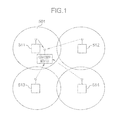
- FIG. 1 is an exemplification diagram illustrating a scene not suited to a multi-point coordinated transmission/reception.
- a reference numeral 501 denotes a cover range of a remote radio head.
- a signal received from the remote radio head 511 is extremely strong; however, a signal received from remote radio heads 512 , 513 , and 514 is weak. Therefore, in the above scene; performance is sufficient only by the single point transmission through the remote radio head 511 . Only when the user equipment moves to a peripheral border of the remote radio head 511 , it is considered that the performance needs to be improved by the multi-point transmission.
- a mobile communication system includes a plurality of remote radio heads configured to transmit a signal to user equipment and configure an antenna network; and a centralized baseband pool configured to be connected to the antenna network, wherein the centralized baseband pool performs clustering with respect to the plurality of remote radio heads so as to dynamically vary the number of the remote radio heads each included in a plurality of clusters.
- a remote radio head clustering method for use in a mobile communication system having a plurality of remote radio heads to transmit a signal to user equipment and configure an antenna network and a centralized baseband pool connected to the antenna network.
- the method includes performing clustering with respect to the plurality of remote radio heads so as to dynamically vary the number of the remote radio heads each included in a plurality of clusters.
- the clustering method is dynamic but also a cluster size is variable.
- a cluster size is 1, the single point transmission is used, and on the other hand, when a cluster size is larger than 1, the multi-point transmission is used.
- the clustering method based on a “clustering gain” is used, and after all, which transmission method is used is determined as well as each cluster size is determined.
- FIG. 1 is an exemplification diagram illustrating a scene not suited to a multi-point coordinated transmission/reception of a conventional technology
- FIG. 2A is a schematic diagram illustrating a clustering result based on a “clustering gain” of the present invention
- FIG. 2B is a schematic diagram illustrating a clustering result based on a “clustering gain” of the present invention
- FIG. 3 is a schematic diagram illustrating an internal function module of a centralized baseband pool of the present invention
- FIG. 4 is a schematic diagram illustrating a measurement based on a measurement window of the present invention.
- FIG. 5 is a signaling interactive diagram illustrating a dynamic clustering method based on a “clustering gain” of the present invention
- FIG. 6 is an algorithm flowchart illustrating a dynamic clustering method based on a “clustering gain” of the present invention.
- FIG. 7A illustrates a simple implementation example of a dynamic clustering method based on a “clustering gain” of the present invention
- FIG. 7B illustrates a simple implementation example of a dynamic clustering method based on a “clustering gain” of the present invention
- FIG. 7C illustrates a simple implementation example of a dynamic clustering method based on a “clustering gain” of the present invention
- FIG. 8 illustrates a distribution antenna system based on an LTE/LTE-A base station of a conventional technology
- FIG. 9 is a system frame diagram illustrating a distribution antenna system based on a centralized baseband pool of a conventional technology
- FIG. 10 is a schematic diagram illustrating static clustering of a remote radio head of a conventional technology, in which a cluster size is fixed;
- FIG. 11A is a schematic diagram illustrating dynamic clustering of a remote radio head in a distribution antenna system of a conventional technology, in which a cluster size is fixed;
- FIG. 11B is a schematic diagram illustrating dynamic clustering of a remote radio head in a distribution antenna system of a conventional technology, in which a cluster size is fixed.
- Embodiments of the present invention will be described below with reference to FIGS. 2A to 6 .
- a distribution antenna system based on a centralized baseband pool of the present invention is obtained by improving the distribution antenna system based on the centralized baseband pool of a conventional technology illustrated in FIG. 9 . Accordingly, only points different from a conventional technology will be described in detail.
- a mobile communication system of the present invention includes a plurality of remote radio heads which transmit signals to user equipment and configure an antenna network, and a centralized baseband pool connected to the antenna network.
- the centralized baseband pool performs clustering to the plurality of remote radio heads so as to dynamically vary the number of the remote radio heads included in each of a plurality of clusters.
- the number of the remote radio heads included in each of the plurality of clusters dynamically varies between one to n (n is a natural number of 2 or more).
- the centralized baseband pool further performs clustering to the plurality of remote radio heads in the ascending order of the number of the included remote radio heads.
- the centralized baseband pool further performs clustering to the plurality of remote radio heads based on an SINR value to each user equipment.
- the remote radio heads different in the number are further included in each cluster.
- FIGS. 2A and 2B are schematic views of clustering results based on a “clustering gain” of the present invention.
- the clustering results dynamically vary between multi-point transmission and single point transmission.
- the remote radio heads 601 and 602 belong to clusters 2 and 5 , respectively, and stay in a single point transmission state.
- the remote radio heads 601 and 602 belong to clusters 2 and 5 , respectively, and stay in a single point transmission state.
- the remote radio head 601 configures a cluster 1 having a cluster size of 2, and on the other hand, along with the other two remote radio heads; the remote radio head 602 configures a cluster 4 having a cluster size of 3, and stays in a multi-point transmission state.
- a configuration of the centralized baseband pool of the present invention will be described below with reference to FIG. 3 .
- FIG. 3 is a schematic diagram illustrating an internal function module of the centralized baseband pool of the present invention.
- the centralized baseband pool 901 has a system parameter database 701 including a user's priority information memory 702 , a measurement information memory 703 , and a channel state information memory 704 , a user scheduling unit 706 , a dynamic clustering controller 707 , a radio resource management unit 708 , and a plurality of cluster signal processing units 709 .
- system parameter database 701 all parameters for fixed setting and manual setting of a network such as a radio bearer parameter, a power control parameter, and a switching parameter are stored.
- a radio bearer parameter such as a radio bearer parameter, a power control parameter, and a switching parameter.
- the user's priority information memory 702 stores a scheduling priority of users.
- Each RRH has a sheet of user's priority list table, and is discriminated by an ID of the remote radio head. A specific generation process will be described later in a portion for the user scheduling unit 706 .
- the measurement information memory 703 stores information on an adjacent remote radio head arranged in each of the remote radio heads.
- the system transmits one row (a main service remote radio head corresponding to the mobile station) from this list table to the corresponding mobile station, and allows it to perform measurement.
- an effective measurement range and feedback overhead of the mobile station can be largely reduced.
- a table 2 represents a typical example of a manually set measurement information table.
- a first column represents remote radio head IDs of the entire network. Any of these remote radio heads can serve as a main service remote radio head for user equipment.
- the main service remote radio head is a remote radio head which transmits a best receive signal, and can provide network interactive signaling information for the user equipment.
- Second to last columns represent adjacent remote radio heads arranged for these remote radio heads.
- a mobile station measures only channel state information on the main service remote radio head and the adjacent remote radio head. For example, when the main service remote radio head for user equipment is an RRH 3 , the network transmits a measurement control message including a row corresponding to the RRH 3 to the user equipment.
- the mobile station measures also channel state information on RRH 2 , RRH 4 , RRH 6 , RRH 7 , and RRH 8 in addition, to the RRH 3 .
- RRH 2 , RRH 4 , RRH 6 , RRH 7 , and RRH 8 in addition, to the RRH 3 .
- six adjacent remote radio heads can be arranged at a maximum.
- the parameters can be adjusted according to complexity and performance.
- the measurement setting is implemented through a quadrangular or circular measurement window.
- a measurement method through the quadrangular measurement window is as illustrated in FIG. 4 .
- a table 3 represents a typical example of a measurement information table based on the quadrangular measurement window of an RRH distribution illustrated in FIG. 4 .
- the channel state information memory 704 stores the measured channel state information corresponding to different user equipment. Each user equipment reports measurements of the channel state information between the main service remote radio head and each adjacent remote radio head based on contents of the measurement information table (table 2). The channel state information table as indicated in a table 4 is obtained, and stored in the measurement information memory 703 .
- the received or transmission waiting user data is stored.
- the user scheduling unit 706 performs scheduling to a user of the system.
- a large amount of non-real time packet data work is present. Since the total channel capacity of the system is limited, the user scheduling unit 706 needs to determine a type of work based on a QoS request of the user, select several users, and perform service in a predetermined time.
- the user uses a total buffer business model.
- Any of the respective RRHs calculate priority parameters of my own user based on the proportional fair principle, dispose them in the descending order, and acquire a user's priority list table, thus storing them in the user's priority information memory 702 .
- a method for specifically calculating a priority parameter of a certain user k is as represented in a formula 1.
- a symbol r k denotes a real time transmission rate of the scheduling time
- a symbol R k denotes an average transmission rate in a time window in a past certain fixed period of the user k.
- the dynamic clustering controller 707 is a most important portion of the present invention.
- the dynamic clustering controller 707 performs clustering based on a “clustering gain”, and performs switching between the single point transmission and the multi-point transmission (or, between the multi-point transmissions with different cluster sizes).
- the radio resource management unit 708 mainly performs resource allocation such as power allocation with respect to the separated clusters.
- the cluster signal processing unit 709 is generated in real time according to results of the dynamic clustering controller 706 .
- the centralized baseband pool 901 has n pieces of cluster signal processing units.
- the cluster signal processing unit 709 mainly performs signal processing in clusters, for example, coordination precoding, modtilation/demodulation, coding/decoding, and frequency spread/inverse spread.
- FIG. 4 is a measurement schematic diagram based on a measurement window of the present invention.
- a measurement range is a quadrangular area having a length of X meters and a width of Y meters with a central focus on specific positions (e.g., longitude and latitude) of a main service RRH, called a quadrangular measurement window 801 , and X and Y are arbitrarily set, if necessary.
- Each of the RRHs in this area automatically serves as an RRH measured by User Equipment (UE).
- UE User Equipment
- the measurement range includes RRHs in the quadrangular measurement window at the upper left.
- the measurement range includes six RRHs in the quadrangular measurement window at the lower right; namely, includes R 7 , R 8 , R 11 , R 12 , R 15 , and R 16 .
- analogy is performed.
- this is semiautomatic measurement setting.
- a size of the quadrangular area can be flexibly changed based on the amount of work of a network at present, and the network further performs searching from a database based on a size of the set measurement window.
- the centralized baseband pool uses a relatively large quadrangular area, increases the number of coordinated cells, imparts UE a better room for selection, and averages a part of the load into the above cells.
- FIG. 5 is a signaling interactive diagram of a dynamic clustering method based on a “clustering gain” of the present invention.
- the centralized baseband pool 901 transmits a measurement control message to the remote radio heads R 1 , R 2 , . . . , and RN.
- the measurement control message includes a measurement information field including a measurement ID, measurement subject information, and measurement report setting.
- a measurement subject information field an adjacent remote radio head list table is included. Specifically, one row of the main service remote radio head corresponding to the mobile station of the table 1 is used for measuring the corresponding channel state information through the mobile station.
- the centralized baseband pool 901 needs to further provide setting information including the number of reference signal ports and reference signal pattern (CSI-RS pattern) of each RRH to be measured.
- CSI-RS pattern reference signal pattern
- the user equipment D 1 , D 2 , . . . , and Dm performs channel estimation according to the received signals, and calculates channel state information between the user equipment and each of the main service remote radio head and the adjacent remote radio head.
- the user equipment D 1 , D 2 , . . . , and Dm transmits the measurement report message including the measured remote radio head ID and the corresponding channel state information to the centralized baseband pool 901 via a network and switchers.
- the centralized baseband pool 901 receives the channel state information transmitted from the user equipment D 1 , D 2 , . . . , and Dm, and then updates the channel state information stored in the channel state information memory 704 .
- a format of the channel state information is as illustrated in FIG. 9 .
- the user scheduling unit 706 of the centralized baseband pool 901 performs sorting to users of each RRH based on the proportional fair principle.
- the user scheduling unit 706 updates the user's priority information stored in the user's priority information memory 702 .
- the dynamic clustering controller 707 performs clustering by using a method based on the “clustering gain”. The above method will be described later with reference to FIG. 6 .
- the centralized baseband pool 901 dynamically generates the information processing unit 709 of each cluster.
- the centralized baseband pool 901 allocates radio resources according to each cluster.
- the centralized baseband pool 901 transmits processed data to each antenna port of the remote radio heads R 1 , R 2 , . . . , and RN.
- the remote radio heads R 1 , R 2 , . . . , and RN each provide for the user equipment a service of the single point transmission or multi-point transmission.
- a dynamic switching method being a transmission system of the distribution antenna system of the present invention will be described below with reference to FIG. 6 .
- FIG. 6 is an algorithm flowchart illustrating a dynamic clustering method based on the “clustering gain” of the present invention.
- step 1001 when user equipment having highest priority is selected from the user's priority list table (refer to the table 1) of each RRH, M pieces of user equipment are selected (M ⁇ N, N represents the total number of the RRHs of the network).
- the RRHs are initialized, B is set to a set of N pieces of the RRHs, and U is set to a set of M pieces of the user equipment.
- an Signal to Interference-plus-Noise Ratio (SINR) of M pieces of the user equipment is calculated based on the single point transmission.
- SINR Signal to Interference-plus-Noise Ratio
- SINR 1 ⁇ ( k ) ⁇ h ik ⁇ w i ⁇ 2 ⁇ P i ⁇ j ⁇ i , j ⁇ S i ⁇ ⁇ h jk ⁇ w j ⁇ ⁇ P j + N Formula ⁇ ⁇ 2
- a numerator represents a received effective signal
- h ik represents channel state information from the main service remote radio head RRH i to the UE k
- wi represents a precoding matrix from the RRH i
- P i represents transmission power from the RRH i
- a first term of a denominator represents interference
- si represents an adjacent remote radio head set, of the main service remote radio head RRH i to which user equipment belongs
- h jk represents channel state information from the adjacent service remote radio head RRH j to the UE k
- a second term N of the denominator represents additive Gaussian white noise.
- the distribution antenna system determines whether an SINR 1 of the user equipment is larger than a threshold T 1 . If Yes, this user equipment belongs to a user located at the center of the cell, or interference is small. If the SINR 1 is smaller than the threshold T 1 , this user equipment belongs to a user located at the edge of the cell, or interference is large.
- the threshold T 1 is a predetermined value.
- the dynamic clustering controller 707 fine adjusts this value based on conditions of a current network load from a pair of experience values (e.g., ⁇ 1 dB, 0 dB, 1 dB, and 2 dB ⁇ ).
- the dynamic clustering controller 707 allocates the main service RRH to a user in which the SINR is larger than the T 1 to perform the single point transmission, sets to 1 a size of the cluster to which the user belongs, and writes its results in a clustering result table.
- the RRH and user equipment already combined into a pair are deleted from the sets B and U, respectively.
- one RRH is here supposed to belong to only one cluster at one time zone, and fail to be jointly used by a plurality of clusters.
- One user equipment is further supposed to belong to only one cluster at one time zone, and fail to use resources for a plurality of clusters at the same time.
- the distribution antenna system determines whether the set B of RRHs waiting to be selected at this time is an empty set, that is, RRHs are already allocated. If Yes, the algorithm terminates. If No, the process proceeds to step 1007 .
- the distribution antenna system determines whether the set U of user equipment waiting to be selected at this time is an empty set, that is, user equipment receives service. If Yes, the algorithm terminates. If No, the process proceeds to step 1008 .
- the distribution antenna system adds 1 to a cluster size c, and prepares for determination of the multi-point transmission of the next priority.
- the distribution antenna system determines whether a cluster size c of this time exceeds the limit of a maximum cluster size C max . If Yes, the process advances to step 1013 . On the other hand, if No, the process proceeds to step 1010 .
- a multi-point coordination service it is not necessary to use a number of “points”. As the number of points increases more, not only complexity rapidly increases more but also overhead of a send-back link increases more. Also, a gain of the multi-point transmission further reaches a saturation state. Therefore, in the actual, system, the maximum number of points of the multi-point transmission, namely, the maximum value C max of the cluster size here said ought to be limited. Based on an experience value, this value is normally set to 3 or 4.
- a combination is performed according to the cluster size c by using the remaining RRHs.
- Each RRH is set as the main service RRH, c ⁇ 1 pieces of RRHs are selected from a set of all available adjacent RRHs of the measurement information table (e.g., table 2 or 3) to combine a cluster having a size c, thus creating
- An SINR c of the user equipment k is represented by a formula 3.
- SINR c ⁇ ( k ) ⁇ i ⁇ C ⁇ ⁇ h ik ⁇ w i ⁇ 2 ⁇ P i ⁇ j ⁇ C , j ⁇ S l ⁇ ⁇ h jk ⁇ w j ⁇ ⁇ P j + N
- C represents a set of the RRHs included in a cluster which provides service for user equipment.
- a numerator represents effective signals received by the user equipment.
- the main service RRH 1 of the user equipment is necessarily included in the cluster.
- a first term of the denominator represents interference outside the cluster, and is mainly derived from RRHs belonging to a set S 1 of the adjacent remote radio heads of the main service remote radio head, RRH 1 , failing to belong to this cluster, to which the user equipment belongs.
- a specific description on a parameter is the same as that of the measurement control message of step 902 of FIG. 4 .
- ⁇ i ⁇ B ⁇ C S j c - 1 is calculated.
- a clustering gain G c for simultaneously providing service for multiple user equipment is as represented in a formula 4.
- R c is a sum of data rates obtained by the multi-point coordination service of the cluster through the user equipment belonging to the cluster c.
- R 1 is a sum of data rates obtained by the single cell service through the user equipment belonging to the cluster c.
- a clustering gain table is obtained.
- a table 6 illustrates a display example of the clustering gain having a cluster size of 3.
- all combinations of available RRHs are arranged, and RRHs in the cluster ought to be selected based on the measurement information table as a restrictive condition.
- a combination of the same RRH appears, only one of the combinations is held. For example, when cluster information overlapped in clusters 1 and 4 of the table 6 is included, namely, the same RRHs are included in the cluster, data of the cluster 4 is deleted.
- the distribution antenna system searches the clustering gain table from top to bottom based on a Greedy method, and selects a cluster which satisfies conditions in which G, is larger than T c .
- this cluster is not selected again.
- G c the clustering gain
- a sum of rates obtained by all the user equipment of the cluster having a size c is divided by a sum of rates obtained at the time when all of the above user equipment uses the single point transmission. Therefore, in order that the multi-point transmission may have a gain, the G C ought to be at least larger than 1.
- the O c is a gain factor of the multi-point transmission in which a cluster size is c.
- a gain of the multi-point transmission is obtained by consuming extra resources for a part of the system, and includes an extra signaling overhead for transmission, an RE resource occupation overhead (e.g., pilot occupation), and a calculation complexity overhead.
- a user equipment feedback overhead for the multi-point transmission in which a cluster size is c is sometimes more than c times of that for the single point transmission.
- the multi-point transmission is simply 2c times as much as the single point transmission in the resource occupation overhead (e.g., pilot occupation) of RE.
- the resource occupation overhead e.g., pilot occupation
- the O C is supposed to perform dynamic allocation based on an actual desirable value for management, and this value is supposed to become large according to an increase in c.
- the value is present in the range of 0.1 to 0.4.
- the feedback is not ideal by the effect of design of a code book, quantization error, and a delay of feedback. Therefore, this value can be appropriately adjusted downward.
- the main service RRH is allocated to the remaining user equipment which fails to satisfy conditions to perform the single point transmission.
- a dynamic switching method for use in a transmission system of the distribution antenna system of the present invention is described above.
- the present invention is not limited, thereto, and can be changed according to need.
- the cluster size c is increased one by one to perform clustering.
- a value of the cluster size c at the time of performing clustering and a change order of the cluster size c are appropriately changeable depending on the situation.
- FIG. 7 illustrates a simple example of the dynamic clustering method based on the “clustering gain” of the present invention. As illustrated in FIG. 7 , nine remote radio service heads are arranged in a network, and represented by using numerals of 1 to 9, respectively. A maximum cluster size is set to 3.
- Step 1 According to step 1001 of FIG. 6 , one RRH having a largest priority is selected from a user's priority list table of each RRH.
- a measurement information table as illustrated in a table 7 is here created according to a method illustrated in FIG. 4 .
- Each row of this measurement information table corresponds to one scheduled user.
- a channel state information table as illustrated in a table 8 is obtained based on the channel state information fed back from the user.
- each user calculates an SINR of the single point transmission according to the method of step 1003 illustrated in FIG. 6 and acquires SINR values as indicated in a table 9.
- the threshold T 1 is set to 1 dB. Since the SINR values of users 1 and 5 exceed the threshold T 1 by calculations, the users 1 and 5 perform the single point transmission through the main service base station, respectively. A table of clustering results of this time is as indicated in a table 10.
- Step 2 The allocated RRH, users (UE 1 , UE 5 , RRH 1 , and RRH 5 ), and corresponding channel state information are deleted.
- a combination is performed with respect to the RRHs according to the method of step 1010 illustrated in FIG. 6 .
- a clustering gain of two point transmission is calculated and a table 12 of a clustering gain list is obtained.
- combination results of the overlapped RRHs are deleted.
- the table 12 is newly sorted out, the overlapped cluster data is deleted, and the cluster data is arranged as indicated in a table 13 in the descending order of the clustering gain value.
- a combination in which G 2 is larger than T 2 is selected.
- the clusters selected through the algorithm of Greedy are ⁇ 4, 7 ⁇ and ⁇ 8, 9 ⁇ .
- a cluster result table as indicated in a table 14 is obtained.
- Step 3 The allocated RRH, users, and corresponding channel state information are deleted to acquire a table 15.
- the combination is performed with respect to the RRH according to the method of step 1010 illustrated in FIG. 6 , and combination results of the overlapped RRHs are deleted.
- the cluster selected through the algorithm of Greedy is ⁇ 2, 3, 6 ⁇ .
- a clustering result table as indicated in a table 17 is then obtained.
- one cluster (namely, a cluster denoted by numerals 2 , 3 , and 6 ) having a cluster size of 3 is further obtained, and a clustering state is as illustrated in FIG. 7C .
- the mobile communication system and remote radio head clustering method thereof of the present invention are described above. Subsequently, different points between the present invention and the conventional technology are simply compared with each other.
- a cluster size is fixed, and on the other hand, a cluster size is dynamically varied in the dynamic clustering method of the present invention. That is, all the cluster sizes of multiple included clusters are not the same as each other in a certain scheduling time.
- a cluster in which the number of the remote radio heads is smaller than the cluster size is present.
- a cluster size is 2 as illustrated in FIGS. 11A and 11B , for example, when the number of the remote radio heads is 17, a cluster having two remote radio heads is present, and at the same time, a cluster having one remote radio head is necessarily present.
- the presence of the cluster in which the number of the remote radio heads, is different from each other is passive, and the essence thereof is different from the present invention.
- the present invention actively changes the number of the remote radio heads in each cluster and reasonably allocates the remote radio heads in the distribution antenna system based on the centralized baseband pool.
Landscapes
- Engineering & Computer Science (AREA)
- Computer Networks & Wireless Communication (AREA)
- Signal Processing (AREA)
- Mobile Radio Communication Systems (AREA)
Applications Claiming Priority (3)
| Application Number | Priority Date | Filing Date | Title |
|---|---|---|---|
| CN201110056054 | 2011-03-02 | ||
| CN201110056054.6A CN102655677B (zh) | 2011-03-02 | 2011-03-02 | 移动通信系统及其远端射频单元分簇方法 |
| CNCN201110056054.6 | 2011-03-02 |
Publications (2)
| Publication Number | Publication Date |
|---|---|
| US20120224541A1 US20120224541A1 (en) | 2012-09-06 |
| US8908602B2 true US8908602B2 (en) | 2014-12-09 |
Family
ID=46731188
Family Applications (1)
| Application Number | Title | Priority Date | Filing Date |
|---|---|---|---|
| US13/403,096 Expired - Fee Related US8908602B2 (en) | 2011-03-02 | 2012-02-23 | Clustering method of mobile communication and remote radio head thereof |
Country Status (3)
| Country | Link |
|---|---|
| US (1) | US8908602B2 (enExample) |
| JP (1) | JP5697622B2 (enExample) |
| CN (1) | CN102655677B (enExample) |
Cited By (2)
| Publication number | Priority date | Publication date | Assignee | Title |
|---|---|---|---|---|
| US20180295674A1 (en) * | 2015-10-08 | 2018-10-11 | Telefonaktiebolaget Lm Ericsson (Publ) | Combining uplink radio signals |
| US20190045583A1 (en) * | 2016-02-03 | 2019-02-07 | Nokia Solutions And Networks Oy | Multiconnectivity cluster |
Families Citing this family (39)
| Publication number | Priority date | Publication date | Assignee | Title |
|---|---|---|---|---|
| US8934561B2 (en) * | 2011-12-28 | 2015-01-13 | Nokia Siemens Networks Oy | Cell clustering and aperture selection |
| US9042941B2 (en) | 2011-12-28 | 2015-05-26 | Nokia Solutions And Networks Oy | Uplink grouping and aperture apparatus |
| WO2014046581A1 (en) * | 2012-09-21 | 2014-03-27 | Telefonaktiebolaget Lm Ericsson (Publ) | Network node and method performed by a network node for controlling connectivity of a radio resource unit to a base band unit |
| US8913972B2 (en) | 2012-10-11 | 2014-12-16 | Nokia Siemens Networks Oy | Antenna clustering for multi-antenna aperture selection |
| CN103051370B (zh) * | 2012-12-28 | 2016-12-28 | 华为技术有限公司 | 一种用户设备的工作拉远射频单元选择方法和基站 |
| CN103117959A (zh) * | 2013-01-17 | 2013-05-22 | 中国联合网络通信集团有限公司 | 资源重分配方法、信息收集设备和资源管理设备 |
| CN104080177B (zh) * | 2013-03-28 | 2019-01-11 | 株式会社Ntt都科摩 | 协作多点调度方法和基站 |
| CN104159258B (zh) * | 2013-05-15 | 2018-03-02 | 电信科学技术研究院 | 一种通信节点状态调整方法、装置及系统 |
| WO2015037857A1 (ko) * | 2013-09-10 | 2015-03-19 | 엘지전자 주식회사 | Bbu의 rru 정보 획득 방법 및 bbu |
| US10045333B2 (en) * | 2013-11-07 | 2018-08-07 | Lg Electronics Inc. | Method for updating terminal-centered coverage |
| JP6267561B2 (ja) * | 2014-03-26 | 2018-01-24 | Kddi株式会社 | 制御装置、制御方法及びプログラム |
| CN103986507B (zh) * | 2014-05-20 | 2017-12-05 | 大唐移动通信设备有限公司 | 一种信息发送方法及一种rrh |
| CN113490283B (zh) | 2014-06-09 | 2024-10-25 | 艾尔瓦纳有限合伙公司 | 在无线电接入网络中调度相同的资源 |
| CN104066196B (zh) * | 2014-06-30 | 2018-07-13 | 华为技术有限公司 | 确定拉选射频单元rru的方法与设备 |
| KR101872658B1 (ko) * | 2014-11-29 | 2018-06-28 | 후아웨이 테크놀러지 컴퍼니 리미티드 | 무선 인터페이스 용량 밀도를 조절하기 위한 방법 및 장치 |
| JP6623516B2 (ja) | 2014-12-17 | 2019-12-25 | 富士通株式会社 | 無線通信システム、無線基地局、ベースバンドユニット、制御装置、および無線通信方法 |
| CN104507150B (zh) * | 2014-12-23 | 2018-07-31 | 西安电子科技大学 | 一种基带池内虚拟资源分簇方法 |
| CN104507166B (zh) * | 2014-12-23 | 2018-07-17 | 西安电子科技大学 | 一种基带池内共享虚拟资源配置方法 |
| CN105120467B (zh) * | 2015-09-07 | 2018-08-14 | 重庆邮电大学 | 一种增强网络容量与覆盖的动态分布式天线部署方法 |
| WO2017058607A1 (en) * | 2015-09-30 | 2017-04-06 | Commscope Technologies Llc | Power cabling connections for remote radio heads and related methods |
| WO2017070908A1 (zh) * | 2015-10-29 | 2017-05-04 | 华为技术有限公司 | 信号传输装置及方法 |
| CN105721026B (zh) * | 2015-12-31 | 2019-12-17 | 华为技术有限公司 | 一种联合数据传输方法及设备 |
| CN108702807A (zh) * | 2016-02-05 | 2018-10-23 | 华为技术有限公司 | 一种降低系统干扰的方法及装置 |
| KR101719491B1 (ko) * | 2016-03-29 | 2017-03-24 | 서울대학교산학협력단 | 메시지 패싱을 이용한 동적 셀 클러스터링 방법, 장치, 프로그램 및 이를 기록한 기록매체 |
| US10064019B2 (en) * | 2016-06-29 | 2018-08-28 | Nokia Technologies Oy | Single frequency network using Ethernet multicast |
| JP6646224B2 (ja) * | 2016-07-15 | 2020-02-14 | 富士通株式会社 | 制御装置、通信システム、及び無線制御方法 |
| CN106385689A (zh) * | 2016-09-26 | 2017-02-08 | 珠海市魅族科技有限公司 | 灵活双工的fdd系统的干扰协调方法、装置及基站 |
| CN106452653A (zh) * | 2016-11-11 | 2017-02-22 | 上海电机学院 | 一种分布式多天线系统对宏蜂窝基站干扰的抑制方法 |
| CN106788647B (zh) * | 2016-11-11 | 2020-11-10 | 上海电机学院 | 一种微蜂窝多天线系统自适应分簇的调整方法 |
| JP6864106B2 (ja) * | 2017-02-21 | 2021-04-21 | テレフオンアクチーボラゲット エルエム エリクソン(パブル) | デュアルプロトコルスタックユーザ機器と、無線アクセス電気通信ネットワークの2つのベースバンドユニットとの間のデュアルコネクティビティのための、方法およびデバイス |
| US11678358B2 (en) | 2017-10-03 | 2023-06-13 | Commscope Technologies Llc | Dynamic downlink reuse in a C-RAN |
| CN109803269B (zh) * | 2017-11-17 | 2021-07-09 | 华为技术有限公司 | 组网方法和装置、网络接入方法、以及用户设备 |
| TWI650037B (zh) * | 2017-12-05 | 2019-02-01 | 財團法人工業技術研究院 | 一種集中式無線存取網路控制方法 |
| US10645705B1 (en) * | 2018-07-02 | 2020-05-05 | Sprint Spectrum L.P. | Use of successive interference cancellation and non-orthogonal coding to facilitate uplink communication from multiple devices on shared air interface resources |
| CN110177340B (zh) * | 2019-07-15 | 2020-10-20 | 电子科技大学 | 一种以用户为中心的超密集网络资源分配方法 |
| CN110572847B (zh) * | 2019-09-29 | 2021-05-28 | 京信通信系统(中国)有限公司 | 数据传输方法、系统、计算机设备和存储介质 |
| WO2021133393A1 (en) * | 2019-12-26 | 2021-07-01 | Intel Corporation | Apparatus, system and method of wireless communication by an integrated radio head |
| CN113316093B (zh) * | 2020-02-26 | 2023-04-07 | 成都鼎桥通信技术有限公司 | 通信方法、装置及存储介质 |
| US11812518B2 (en) * | 2020-11-17 | 2023-11-07 | Microsoft Technology Licensing, Llc | Virtualized radio access network (vRAN) decoding as a service |
Citations (12)
| Publication number | Priority date | Publication date | Assignee | Title |
|---|---|---|---|---|
| WO2007056891A1 (en) | 2005-11-16 | 2007-05-24 | Zte Corporation | A up-link synchronization method in mobile communication system |
| CN101389115A (zh) | 2008-11-07 | 2009-03-18 | 北京工业大学 | 一种多小区基站动态成簇的协作通信方法 |
| CN101562900A (zh) | 2008-04-16 | 2009-10-21 | 中兴通讯股份有限公司 | 基于共享基带池和分布式射频单元的系统和方法 |
| CN101577940A (zh) | 2009-06-11 | 2009-11-11 | 中国科学技术大学 | 分布式天线系统的用户设备调度方法 |
| CN101631379A (zh) | 2009-06-19 | 2010-01-20 | 东南大学 | 分布式天线移动通信系统的功率分配与天线选择方法 |
| WO2010077192A1 (en) | 2008-12-29 | 2010-07-08 | Telefonaktiebolaget L M Ericsson (Publ) | Subcell measurement procedures in a distributed antenna system |
| CN101777941A (zh) | 2009-01-12 | 2010-07-14 | 华为技术有限公司 | 协作多点传输系统中的下行传输方法、网络设备和无线系统 |
| WO2010124647A1 (zh) | 2009-04-30 | 2010-11-04 | 株式会社日立制作所 | 移动通信中基站动态分簇的设备和方法 |
| US20100290413A1 (en) | 2009-05-14 | 2010-11-18 | Hitachi, Ltd. | Radio base station apparatus |
| US20110312363A1 (en) * | 2010-06-17 | 2011-12-22 | Nokia Siemens Networks Oy | Optimizing Control Channel Performance With Virtual Inter-Cell Coordination |
| US20130201953A1 (en) * | 2010-09-30 | 2013-08-08 | Lg Electronics Inc. | Method for transmitting signal in multi-node system |
| US20130286997A1 (en) * | 2011-02-07 | 2013-10-31 | Intel Corporation | Wireless communication sysytem with common cell id |
Family Cites Families (1)
| Publication number | Priority date | Publication date | Assignee | Title |
|---|---|---|---|---|
| CN101175261B (zh) * | 2007-11-28 | 2010-09-29 | 中兴通讯股份有限公司 | 一种在基带池中传输多模正交数据的接口及方法 |
-
2011
- 2011-03-02 CN CN201110056054.6A patent/CN102655677B/zh not_active Expired - Fee Related
-
2012
- 2012-02-23 US US13/403,096 patent/US8908602B2/en not_active Expired - Fee Related
- 2012-03-01 JP JP2012045011A patent/JP5697622B2/ja not_active Expired - Fee Related
Patent Citations (15)
| Publication number | Priority date | Publication date | Assignee | Title |
|---|---|---|---|---|
| WO2007056891A1 (en) | 2005-11-16 | 2007-05-24 | Zte Corporation | A up-link synchronization method in mobile communication system |
| CN101185270A (zh) | 2005-11-16 | 2008-05-21 | 中兴通讯股份有限公司 | 移动通信系统中的上行同步方法 |
| CN101562900A (zh) | 2008-04-16 | 2009-10-21 | 中兴通讯股份有限公司 | 基于共享基带池和分布式射频单元的系统和方法 |
| CN101389115A (zh) | 2008-11-07 | 2009-03-18 | 北京工业大学 | 一种多小区基站动态成簇的协作通信方法 |
| WO2010077192A1 (en) | 2008-12-29 | 2010-07-08 | Telefonaktiebolaget L M Ericsson (Publ) | Subcell measurement procedures in a distributed antenna system |
| CN101777941A (zh) | 2009-01-12 | 2010-07-14 | 华为技术有限公司 | 协作多点传输系统中的下行传输方法、网络设备和无线系统 |
| US20110268077A1 (en) | 2009-01-12 | 2011-11-03 | Lei Wan | Downlink transmission method in a coordinated multi-point transmission system, network device, and wireless system |
| WO2010124647A1 (zh) | 2009-04-30 | 2010-11-04 | 株式会社日立制作所 | 移动通信中基站动态分簇的设备和方法 |
| US20100290413A1 (en) | 2009-05-14 | 2010-11-18 | Hitachi, Ltd. | Radio base station apparatus |
| JP2010268192A (ja) | 2009-05-14 | 2010-11-25 | Hitachi Ltd | 無線基地局装置 |
| CN101577940A (zh) | 2009-06-11 | 2009-11-11 | 中国科学技术大学 | 分布式天线系统的用户设备调度方法 |
| CN101631379A (zh) | 2009-06-19 | 2010-01-20 | 东南大学 | 分布式天线移动通信系统的功率分配与天线选择方法 |
| US20110312363A1 (en) * | 2010-06-17 | 2011-12-22 | Nokia Siemens Networks Oy | Optimizing Control Channel Performance With Virtual Inter-Cell Coordination |
| US20130201953A1 (en) * | 2010-09-30 | 2013-08-08 | Lg Electronics Inc. | Method for transmitting signal in multi-node system |
| US20130286997A1 (en) * | 2011-02-07 | 2013-10-31 | Intel Corporation | Wireless communication sysytem with common cell id |
Cited By (3)
| Publication number | Priority date | Publication date | Assignee | Title |
|---|---|---|---|---|
| US20180295674A1 (en) * | 2015-10-08 | 2018-10-11 | Telefonaktiebolaget Lm Ericsson (Publ) | Combining uplink radio signals |
| US11382172B2 (en) * | 2015-10-08 | 2022-07-05 | Telefonaktiebolaget Lm Ericsson (Publ) | Combining uplink radio signals |
| US20190045583A1 (en) * | 2016-02-03 | 2019-02-07 | Nokia Solutions And Networks Oy | Multiconnectivity cluster |
Also Published As
| Publication number | Publication date |
|---|---|
| CN102655677A (zh) | 2012-09-05 |
| CN102655677B (zh) | 2015-04-01 |
| US20120224541A1 (en) | 2012-09-06 |
| JP2012182792A (ja) | 2012-09-20 |
| JP5697622B2 (ja) | 2015-04-08 |
Similar Documents
| Publication | Publication Date | Title |
|---|---|---|
| US8908602B2 (en) | Clustering method of mobile communication and remote radio head thereof | |
| Osseiran et al. | Mobile and wireless communications for IMT-advanced and beyond | |
| CN105407474B (zh) | 一种资源管理方法及基站 | |
| CN102316510B (zh) | 一种协作发送点的选择方法及选择装置 | |
| CN101951307B (zh) | 在CoMP下的小区协作集的选择方法 | |
| CN101668295A (zh) | 通信系统中支持协作传输的资源复用方法及系统 | |
| CN103167512B (zh) | 基站天线下倾角确定方法、装置和基站设备 | |
| CN103959837A (zh) | 异构网络中的波束形成协调 | |
| JP2010045783A (ja) | マルチセル協調送信方法 | |
| CN101621834A (zh) | 一种基于SINR门限和令牌的CoMP下行动态协作簇选择方法 | |
| US20140051452A1 (en) | Load-aware dynamic cell selection with interference coordination by fractional reuse for cellular multi-user networks | |
| Georgakopoulos et al. | Coordination multipoint enabled small cells for coalition-game-based radio resource management | |
| US20120243440A1 (en) | Method for feeding back channel state information and determining coordinated multi-point mode and device | |
| CN103491639A (zh) | 一种多点协作中的用户调度方法 | |
| CN106413110B (zh) | 一种调度方法、装置及网络节点 | |
| Becvar et al. | Hierarchical scheduling for suppression of fronthaul delay in C-RAN with dynamic functional split | |
| WO2014094191A1 (en) | Method and apparatus for coordinated multipoint transmission | |
| Costa et al. | Radio resource allocation in multi-cell and multi-service mobile network based on QoS requirements | |
| Kilzi et al. | Analysis of drone placement strategies for complete interference cancellation in two-cell NOMA CoMP systems | |
| CN103220790B (zh) | 控制信道资源的分配方法及装置 | |
| Ramamoorthi et al. | Performance comparison of dual connectivity with CoMP in heterogeneous cellular networks | |
| Li et al. | An effective scheduling scheme for CoMP in heterogeneous scenario | |
| CN105517161A (zh) | 一种下行资源分配方法和基站 | |
| Ghaleb et al. | QoS-aware joint uplink-downlink scheduling in FDD LTE-Advanced with carrier aggregation | |
| Zhou et al. | Joint Scheduling Algorithms for LTE-A CoMP System. |
Legal Events
| Date | Code | Title | Description |
|---|---|---|---|
| AS | Assignment |
Owner name: HITACHI, LTD., JAPAN Free format text: ASSIGNMENT OF ASSIGNORS INTEREST;ASSIGNORS:YOSHIUCHI, HIDEYA;GENG, LU;SIGNING DATES FROM 20120210 TO 20120214;REEL/FRAME:027750/0299 |
|
| CC | Certificate of correction | ||
| FEPP | Fee payment procedure |
Free format text: PAYOR NUMBER ASSIGNED (ORIGINAL EVENT CODE: ASPN); ENTITY STATUS OF PATENT OWNER: LARGE ENTITY |
|
| FEPP | Fee payment procedure |
Free format text: MAINTENANCE FEE REMINDER MAILED (ORIGINAL EVENT CODE: REM.) |
|
| LAPS | Lapse for failure to pay maintenance fees |
Free format text: PATENT EXPIRED FOR FAILURE TO PAY MAINTENANCE FEES (ORIGINAL EVENT CODE: EXP.); ENTITY STATUS OF PATENT OWNER: LARGE ENTITY |
|
| STCH | Information on status: patent discontinuation |
Free format text: PATENT EXPIRED DUE TO NONPAYMENT OF MAINTENANCE FEES UNDER 37 CFR 1.362 |
|
| FP | Lapsed due to failure to pay maintenance fee |
Effective date: 20181209 |