US8899140B2 - System for evacuating cartridges - Google Patents
System for evacuating cartridges Download PDFInfo
- Publication number
- US8899140B2 US8899140B2 US13/165,413 US201113165413A US8899140B2 US 8899140 B2 US8899140 B2 US 8899140B2 US 201113165413 A US201113165413 A US 201113165413A US 8899140 B2 US8899140 B2 US 8899140B2
- Authority
- US
- United States
- Prior art keywords
- tray
- cartridge
- evacuation
- firearm
- movement mechanism
- Prior art date
- Legal status (The legal status is an assumption and is not a legal conclusion. Google has not performed a legal analysis and makes no representation as to the accuracy of the status listed.)
- Active, expires
Links
- 230000007246 mechanism Effects 0.000 claims abstract description 90
- 238000010304 firing Methods 0.000 claims abstract description 18
- 238000004200 deflagration Methods 0.000 claims abstract description 8
- 230000010355 oscillation Effects 0.000 claims description 3
- 230000001360 synchronised effect Effects 0.000 claims description 2
- 238000013459 approach Methods 0.000 claims 1
- 230000000903 blocking effect Effects 0.000 claims 1
- 230000005465 channeling Effects 0.000 claims 1
- 230000007257 malfunction Effects 0.000 description 3
- 230000008901 benefit Effects 0.000 description 2
- 230000037431 insertion Effects 0.000 description 2
- 238000003780 insertion Methods 0.000 description 2
- 230000014759 maintenance of location Effects 0.000 description 2
- 230000003213 activating effect Effects 0.000 description 1
- 238000010586 diagram Methods 0.000 description 1
- 230000000694 effects Effects 0.000 description 1
- 230000005484 gravity Effects 0.000 description 1
- 239000003721 gunpowder Substances 0.000 description 1
- 229910052751 metal Inorganic materials 0.000 description 1
- 239000000843 powder Substances 0.000 description 1
- 230000001681 protective effect Effects 0.000 description 1
- 230000008685 targeting Effects 0.000 description 1
Images


Classifications
-
- F—MECHANICAL ENGINEERING; LIGHTING; HEATING; WEAPONS; BLASTING
- F41—WEAPONS
- F41A—FUNCTIONAL FEATURES OR DETAILS COMMON TO BOTH SMALLARMS AND ORDNANCE, e.g. CANNONS; MOUNTINGS FOR SMALLARMS OR ORDNANCE
- F41A9/00—Feeding or loading of ammunition; Magazines; Guiding means for the extracting of cartridges
- F41A9/54—Cartridge guides, stops or positioners, e.g. for cartridge extraction
- F41A9/56—Movable guiding means
- F41A9/57—Flexible chutes, e.g. for guiding belted ammunition from the magazine to the gun
-
- F—MECHANICAL ENGINEERING; LIGHTING; HEATING; WEAPONS; BLASTING
- F41—WEAPONS
- F41A—FUNCTIONAL FEATURES OR DETAILS COMMON TO BOTH SMALLARMS AND ORDNANCE, e.g. CANNONS; MOUNTINGS FOR SMALLARMS OR ORDNANCE
- F41A9/00—Feeding or loading of ammunition; Magazines; Guiding means for the extracting of cartridges
- F41A9/01—Feeding of unbelted ammunition
- F41A9/06—Feeding of unbelted ammunition using cyclically moving conveyors, i.e. conveyors having ammunition pusher or carrier elements which are emptied or disengaged from the ammunition during the return stroke
- F41A9/09—Movable ammunition carriers or loading trays, e.g. for feeding from magazines
- F41A9/10—Movable ammunition carriers or loading trays, e.g. for feeding from magazines pivoting or swinging
- F41A9/13—Movable ammunition carriers or loading trays, e.g. for feeding from magazines pivoting or swinging in a vertical plane
- F41A9/14—Movable ammunition carriers or loading trays, e.g. for feeding from magazines pivoting or swinging in a vertical plane which is transverse to the barrel axis
-
- F—MECHANICAL ENGINEERING; LIGHTING; HEATING; WEAPONS; BLASTING
- F41—WEAPONS
- F41A—FUNCTIONAL FEATURES OR DETAILS COMMON TO BOTH SMALLARMS AND ORDNANCE, e.g. CANNONS; MOUNTINGS FOR SMALLARMS OR ORDNANCE
- F41A9/00—Feeding or loading of ammunition; Magazines; Guiding means for the extracting of cartridges
- F41A9/29—Feeding of belted ammunition
- F41A9/32—Reciprocating-slide-type belt transporters
- F41A9/33—Reciprocating-slide-type belt transporters with cartridge stripping means
-
- F—MECHANICAL ENGINEERING; LIGHTING; HEATING; WEAPONS; BLASTING
- F41—WEAPONS
- F41A—FUNCTIONAL FEATURES OR DETAILS COMMON TO BOTH SMALLARMS AND ORDNANCE, e.g. CANNONS; MOUNTINGS FOR SMALLARMS OR ORDNANCE
- F41A9/00—Feeding or loading of ammunition; Magazines; Guiding means for the extracting of cartridges
- F41A9/38—Loading arrangements, i.e. for bringing the ammunition into the firing position
- F41A9/39—Ramming arrangements
-
- F—MECHANICAL ENGINEERING; LIGHTING; HEATING; WEAPONS; BLASTING
- F41—WEAPONS
- F41A—FUNCTIONAL FEATURES OR DETAILS COMMON TO BOTH SMALLARMS AND ORDNANCE, e.g. CANNONS; MOUNTINGS FOR SMALLARMS OR ORDNANCE
- F41A9/00—Feeding or loading of ammunition; Magazines; Guiding means for the extracting of cartridges
- F41A9/54—Cartridge guides, stops or positioners, e.g. for cartridge extraction
- F41A9/56—Movable guiding means
Definitions
- the present invention refers to a system for evacuating cartridges from the powder chamber or firing chamber of a firearm, normally a cannon, preferably in the direction of a system for expelling cartridges, following upon deflagration of an ammunition.
- the ammunition is essentially made up of a cartridge containing the gun powder for the deflagration of the ammunition, and a projectile which is fired by the firearm towards the target.
- Such projectiles can be “intelligent”, i.e., comprising a target identifying and targeting system, which is capable of varying the direction of the projectile itself after being shot.
- a system for evacuating cartridges comprises an evacuation tray that is adapted to receive the cartridge subsequent to the firing of the ammunition.
- Such a tray is normally positioned in axis with the barrel of the firearm so as to be able to receive the cartridge. Subsequently, such a tray, through a movement mechanism, is moved so as to allow the cartridge to be definitively expelled.
- Such movement systems are normally slow, reducing the shooting frequency of the firearm, and they are also unstable, since especially in critical conditions, for example, if applied to a ship, in conditions of sea force 6 and more, they often risk to jam the whole firearm since they are not able to carry out their task.
- the present invention proposes to solve such technical drawbacks by making a system for evacuating cartridges that is stable, even in extreme conditions, allowing cartridges to always be expelled by the firing chamber.
- Such a system moreover, reduces the probability of collisions and incidents between the various mechanisms in the case of malfunction of the parts.
- One aspect of the present invention concerns a system for evacuating cartridges in a firearm that is capable of speeding up the time necessary to carry out such an operation, thus making it possible to increase the frequency with which the firearm itself is fired.
- a further aspect of the present invention concerns a safety device that is capable of avoiding collisions between the evacuation system and various mechanisms or systems applied in a firearm.
- FIG. 1 shows the structure of the firearm in which such a system for evacuating cartridges, according to the present invention, is applied;
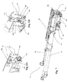
- FIG. 2 illustrates in detail the system according to the present invention, from a side view
- FIG. 3 illustrates the movement mechanism of the tray according to the present invention
- FIG. 4 shows a schematic diagram of the positions that the system can take up when moving
- FIG. 5 illustrates a rear view of the system in position “B” applied onto a firearm
- FIGS. 6A and 6B respectively show the cartridge-retention device ( FIG. 6A ) and the braking device ( FIG. 6B ), according to the present invention
- FIG. 7 illustrates the mechanism for expelling the cartridge with the tray in position “C”
- FIG. 8 illustrates a rear perspective view of the system for evacuating cartridges with the tray in position “C”;
- FIG. 9 illustrates the tray according to the present invention in a rear view.
- the system for evacuating cartridges is applied to a firearm 1 that typically comprises a breech 14 , a firing chamber 12 in which the projectile is fired, coming out of a barrel 13 .
- Such an evacuation system enclosed in a box-type protective structure 11 , comprises an evacuation tray 2 , adapted to receive the cartridge following upon deflagration of an ammunition, and a movement mechanism 3 adapted to move such a tray 2 .
- movement mechanism 3 is a double acting mechanism, i.e. it allows tray 2 to rotate about an axis “X”, that is parallel to the axis of barrel 13 of firearm 1 , to reach an expulsion mechanism 5 for definitively expelling the cartridge and the subsequent return; such a rotation makes it possible to evacuate the cartridge, simultaneously with the loading of an ammunition inside firing chamber 12 by a loading mechanism.
- Such a system for evacuating cartridges further comprises a safety mechanism adapted to move tray 2 in the case in which movement mechanism 3 malfunctions.
- Such a safety mechanism prevents onset of damage consequent upon the impact of tray 2 with the loading mechanism, adapted to insert new ammunition into firing chamber 12 .
- Tray 2 is preferably circular-shaped, with dimensions such as to receive the cartridges from firearm 1 , and during its rotation about axis “X” it can take up three different positions, as illustrated in FIG. 4 .
- tray 2 In position “A” tray 2 is aligned with the axis of barrel 13 of firearm 1 , waiting to receive the cartridge.
- Position “B”, defined as the safety position, is the position that tray 2 takes up in the case in which movement mechanism 3 malfunctions.
- Said position “B” is also the intermediate position before returning into position “A”.
- Position “C” is the position that tray 2 takes up when it must be cleared of the cartridge it contained by an expulsion mechanism 5 .
- tray 2 returns to the position “A” so as to receive a further cartridge.
- tray 2 when passing from position “C” to position “A”, tray 2 can, for example, stop in position “B” in the case in which the loading mechanism has not yet finished its operations, averting the possibility of collisions between the parts involved, to then return to position “A” once the loading mechanism has been disengaged.
- tray 2 the rotary movement of tray 2 occurs around axis “X” through a hooking portion 21 , preferably U-shaped, comprised in such a tray 2 , which is hinged to a pin 111 .
- Such a pin 111 is fixed to box-shaped structure 11 through a support flange 112 .
- tray 2 The movement of tray 2 is carried out by movement mechanism which comprises a double acting movement actuator 31 , preferably hydraulic, dedicated to tray 2 , which acts upon tray 2 itself, via a gear mechanism 32 .
- movement mechanism which comprises a double acting movement actuator 31 , preferably hydraulic, dedicated to tray 2 , which acts upon tray 2 itself, via a gear mechanism 32 .
- tray 2 can be synchronised, with the rest of the mechanisms implemented in firearm 1 , in a preset and appropriately cadenced way from a first position “A”, where the cartridge is received, to a second position “C”, in which the cartridge is expelled by an expulsion mechanism 5 , and vice versa.
- tray 2 In normal operation conditions of the evacuation system, when tray 2 receives the cartridge it is received inside tray 2 itself.
- Said tray 2 must respect a certain distance from firing chamber 12 so as to avoid impacts during the recoil of firearm 1 following upon deflagration of the ammunition.
- the position of tray 2 with respect to firing chamber 12 , from which the cartridge comes, varies according to the angle of inclination of firearm 1 .
- tray 2 will be positioned correctly so as to be able to always receive the cartridge.
- Tray 2 comprises a cartridge-retention device 22 and a braking device 23 .
- the cartridge arrives inside tray 2 with a certain speed suitable for the correct insertion into tray 2 .
- the cartridge is inserted inside tray 2 exploiting the recoil of firing chamber 12 consequent to the deflagration of the ammunition.
- the receiving signal is received by a control device, which is suitable for controlling and activating the systems, mechanisms and devices present in firearm 1 , which will activate movement mechanism 3 .
- Such a cartridge-retention device 22 comprises a contact portion 221 with the cartridge, adapted to detect the presence of the cartridge itself inside tray 2 , sending the receiving signal to the control device.
- contact portion 221 is preferably a metallic element that is hinged so as to rotate around an axis, which is preferably perpendicular with respect to the longitudinal axis of the cartridge inserted in tray 2 .
- Braking device 23 is adapted to slow down the cartridge, from firing chamber 12 , in its insertion inside tray 2 , preferably after sending the receiving signal towards the control device by cartridge-retention device 22 .
- Such a braking device 23 makes it possible to avoid collisions between the cartridge and the bottom of tray 2 , in any case allowing retention device 22 to detect the presence of the cartridge inside tray 2 .
- braking device 23 preferably comprises a contact plate 231 , a second lever mechanism 232 , connected to a damper 233 .
- Said plate 231 rotating around a pin with an axis that is preferably perpendicular to the longitudinal axis of the cartridge, comes into contact with the bottom of the cartridge and thanks to the lever mechanism, connected to damper 233 , it slows down the cartridge.
- a buffer 25 for example in rubber, is applied to the bottom of tray 2 , said buffer being adapted to soften impacts of the cartridges if they have not been sufficiently slowed down by braking device 23 .
- the control device When the receiving signal is received by the control device it activates movement mechanism 3 , in a way such as to pass from position “A” to position “C” passing by position “B”, which is preferably about half way between the other two positions.
- position “C” is preferably at a rotation of about 130° of tray 2 with respect to position “A”; consequently, position “B” is preferably at a rotation of about 60° of tray 2 with respect to position “A”.
- the movement of movement mechanism 3 , on tray 2 is preferably decelerated when approaching stroke end, more precisely when approaching position “A” and in position “C”, so as to avoid impact between parts, and so as to reduce oscillations of tray 2 .
- Tray 2 once it has reached position “C”, is freed from the cartridge that was previously contained in the tray itself, by expulsion mechanism 5 , which comprises a rigid tube 51 , adapted to channel the cartridge to be expelled, at least an expulsion actuator 52 , preferably hydraulic, adapted to thrust the cartridge from tray 2 towards tube 51 , through at least one thrust portion 521 comprised in actuator 52 itself.
- expulsion mechanism 5 which comprises a rigid tube 51 , adapted to channel the cartridge to be expelled, at least an expulsion actuator 52 , preferably hydraulic, adapted to thrust the cartridge from tray 2 towards tube 51 , through at least one thrust portion 521 comprised in actuator 52 itself.
- Rigid tube 51 is preferably fixed above breech 14 so as to not get in the way of the various devices comprised in the firearm.
- Said actuator 52 is placed in a position such as to not get in the way of the rotation of tray 2 , preferably parallel to tube 51 . It is supported above tray 2 through at least one support rod 54 preferably fixed both to tube 51 and to box-shaped structure 11 .
- Thrust portion 521 also positioned so as to not get in the way of the movement of tray 2 , is fixed both to actuator 52 and to at least one sliding block 522 adapted to slide along a guide together with such a portion 521 , along the support rod 54 when actuator 52 is activated.
- control device Once the control device has received the positioning signal, it activates actuator 52 , which is in the point of maximum extension, moving portion 521 , which is channeled in a slit 24 in tray 2 .
- Such a slit 24 is preferably formed along the entire length of tray 2 , so as to allow thrust portion 521 to expel the cartridge from tray 2 itself more easily.
- said portion 521 presses against the bottom of the cartridge thrusting it from tray 2 towards tube 51 .
- Expulsion mechanism 5 also comprises a further anti-return device 53 , which activates in the case in which the thrust of actuator 52 on the cartridge is not enough to thrust it beyond tube 51 .
- said device 53 consists of a lock portion 531 , which is placed inside tube 51 in the case in which the cartridge returns towards tray 2 , because the thrust from actuator 52 was not strong enough to make it come out from tube 51 .
- Said device is advantageous in the case in which firearm 1 is at a high angle of inclination, in which the thrust of actuator 52 can be insufficient for the cartridge to pass beyond tube 51 .
- the control device When the cartridge is expelled from th tray 2 , the control device receives a signal of successful expulsion in this way giving tray 2 consent to return to position “A” so as to receive another cartridge.
- the control device activates movement mechanism 3 so as to pass from position “C” to the position “A” passing by position “B”.
- the control device When passing from the second position (C) to the first position (A) of tray 2 , the control device, in the case in which the loading mechanism is still performing its operating steps, makes it possible for the loading mechanism to terminate its operating steps, before allowing movement mechanism 3 to make tray 2 return, to the first position (A), so as to receive a new cartridge.
- movement mechanism 3 before reaching position “A”, in the aforementioned case, movement mechanism 3 is slowed down, once position “B” has been reached, by means of a bypass valve.
- the slowing down of the descent preferably occurs by reducing the pressure in an oleodynamic circuit connected to actuator 31 by opening the bypass valve.
- control device activates movement mechanism 3 so as to bring tray 2 from position “B” towards position “A”.
- Said solution prevents such a tray 2 from getting in the way of the loading mechanism when new ammunition is to be loaded in firearm 1 .
- Said safety mechanism comprises at least one relief valve connected to the oleodynamic circuit that controls actuator 31 .
- Such a relief valve preferably a maximum pressure valve, is activated only in the case in which the loading mechanism reaches a certain operating step without such a tray 2 being moved from position “A”.
- the relief valve opens due to the increase in pressure inside the oleodynamic circuit of actuator 31 that opposes such a movement of tray 2 .
- the relief valve is opened, emptying out the oleodynamic circuit of actuator 31 , since the limit pressure of such a valve is exceeded, preferably 20 Bar.
- tray 2 is physically moved, for example to position “B”, by the structure of the loading mechanism, since tray 2 is free to move.
- Tray 2 is kept in such a position until the loading mechanism terminates its operating steps after which tray 2 goes back down into position “A” since it is still idle.
- Said solution makes it possible to move for example tray 2 into position “B” without causing irreparable damage due to the impact between mechanisms.
- a safety actuator is also comprised which, connected to an oleodynamic circuit, moves tray 2 , for example to position “C” or position “B”, in the case of malfunctioning of movement mechanism 3 , after the relief valve has released tray 2 , exploiting for example part of the power of the loading mechanism.
- the step of loading a new projectile occurs with a very slight delay that corresponds to the time it takes the cartridge to come out summed to the time it takes tray 2 to reach position “B”, since after such a position the system for evacuating cartridges does not get in the way of the loading mechanism.
Landscapes
- Engineering & Computer Science (AREA)
- General Engineering & Computer Science (AREA)
- Portable Nailing Machines And Staplers (AREA)
- Aiming, Guidance, Guns With A Light Source, Armor, Camouflage, And Targets (AREA)
- Toys (AREA)
- Fluid-Pressure Circuits (AREA)
- Chemical And Physical Treatments For Wood And The Like (AREA)
- Drying Of Solid Materials (AREA)
- Buildings Adapted To Withstand Abnormal External Influences (AREA)
Applications Claiming Priority (3)
| Application Number | Priority Date | Filing Date | Title |
|---|---|---|---|
| ITTO2010A000535 | 2010-06-22 | ||
| ITTO2010A0535 | 2010-06-22 | ||
| ITTO2010A000535A IT1400863B1 (it) | 2010-06-22 | 2010-06-22 | Sistema di evacuazione bossoli |
Publications (2)
| Publication Number | Publication Date |
|---|---|
| US20110308127A1 US20110308127A1 (en) | 2011-12-22 |
| US8899140B2 true US8899140B2 (en) | 2014-12-02 |
Family
ID=43558153
Family Applications (1)
| Application Number | Title | Priority Date | Filing Date |
|---|---|---|---|
| US13/165,413 Active 2031-11-11 US8899140B2 (en) | 2010-06-22 | 2011-06-21 | System for evacuating cartridges |
Country Status (12)
| Country | Link |
|---|---|
| US (1) | US8899140B2 (pl) |
| EP (1) | EP2400254B1 (pl) |
| JP (1) | JP5917843B2 (pl) |
| KR (1) | KR101920079B1 (pl) |
| BR (1) | BRPI1103068B1 (pl) |
| CA (1) | CA2743802C (pl) |
| DK (1) | DK2400254T3 (pl) |
| ES (1) | ES2559954T3 (pl) |
| IT (1) | IT1400863B1 (pl) |
| PL (1) | PL2400254T3 (pl) |
| PT (1) | PT2400254E (pl) |
| SG (1) | SG177105A1 (pl) |
Cited By (1)
| Publication number | Priority date | Publication date | Assignee | Title |
|---|---|---|---|---|
| CN104524726A (zh) * | 2014-12-31 | 2015-04-22 | 西安新竹防灾救生设备有限公司 | 一种密封炮闩 |
Families Citing this family (1)
| Publication number | Priority date | Publication date | Assignee | Title |
|---|---|---|---|---|
| CN107238317B (zh) * | 2017-07-21 | 2023-03-31 | 南京理工大学 | 一种电控式枪支退弹装置 |
Citations (7)
| Publication number | Priority date | Publication date | Assignee | Title |
|---|---|---|---|---|
| GB217569A (en) | 1923-06-14 | 1924-09-04 | Schneider & Cie | Improvements in automatic guns |
| US3690216A (en) * | 1968-08-22 | 1972-09-12 | Secr Defence Brit | Loading mechanisms for guns |
| US4244270A (en) | 1978-07-03 | 1981-01-13 | General Electric Company | Feeder for a gun |
| US5111732A (en) * | 1988-09-28 | 1992-05-12 | L'etat Francais | Automatic weapon with small barrel for rapid firing |
| US5563363A (en) * | 1994-06-16 | 1996-10-08 | Giat Industries | Mechanism and method for inserting a munition |
| US5675924A (en) | 1994-12-12 | 1997-10-14 | Fn Herstal S.A. | Ejection device for firearm |
| US6457397B1 (en) | 1999-07-22 | 2002-10-01 | Giat Industries | Loading device for a shell in the cannon chamber of a weapon fitted with a screw breech |
-
2010
- 2010-06-22 IT ITTO2010A000535A patent/IT1400863B1/it active
-
2011
- 2011-06-16 ES ES11170169.4T patent/ES2559954T3/es active Active
- 2011-06-16 PT PT111701694T patent/PT2400254E/pt unknown
- 2011-06-16 PL PL11170169T patent/PL2400254T3/pl unknown
- 2011-06-16 DK DK11170169.4T patent/DK2400254T3/en active
- 2011-06-16 EP EP11170169.4A patent/EP2400254B1/en active Active
- 2011-06-17 CA CA2743802A patent/CA2743802C/en active Active
- 2011-06-20 BR BRPI1103068-2A patent/BRPI1103068B1/pt active IP Right Grant
- 2011-06-20 JP JP2011136035A patent/JP5917843B2/ja active Active
- 2011-06-21 US US13/165,413 patent/US8899140B2/en active Active
- 2011-06-21 SG SG2011045432A patent/SG177105A1/en unknown
- 2011-06-22 KR KR1020110060536A patent/KR101920079B1/ko active Active
Patent Citations (7)
| Publication number | Priority date | Publication date | Assignee | Title |
|---|---|---|---|---|
| GB217569A (en) | 1923-06-14 | 1924-09-04 | Schneider & Cie | Improvements in automatic guns |
| US3690216A (en) * | 1968-08-22 | 1972-09-12 | Secr Defence Brit | Loading mechanisms for guns |
| US4244270A (en) | 1978-07-03 | 1981-01-13 | General Electric Company | Feeder for a gun |
| US5111732A (en) * | 1988-09-28 | 1992-05-12 | L'etat Francais | Automatic weapon with small barrel for rapid firing |
| US5563363A (en) * | 1994-06-16 | 1996-10-08 | Giat Industries | Mechanism and method for inserting a munition |
| US5675924A (en) | 1994-12-12 | 1997-10-14 | Fn Herstal S.A. | Ejection device for firearm |
| US6457397B1 (en) | 1999-07-22 | 2002-10-01 | Giat Industries | Loading device for a shell in the cannon chamber of a weapon fitted with a screw breech |
Non-Patent Citations (1)
| Title |
|---|
| Italian Search Report for Application No. TO20100535 mailed Feb. 17, 2011. |
Cited By (2)
| Publication number | Priority date | Publication date | Assignee | Title |
|---|---|---|---|---|
| CN104524726A (zh) * | 2014-12-31 | 2015-04-22 | 西安新竹防灾救生设备有限公司 | 一种密封炮闩 |
| CN104524726B (zh) * | 2014-12-31 | 2018-05-18 | 西安新竹防灾救生设备有限公司 | 一种密封炮闩 |
Also Published As
| Publication number | Publication date |
|---|---|
| ES2559954T3 (es) | 2016-02-16 |
| KR101920079B1 (ko) | 2018-11-19 |
| US20110308127A1 (en) | 2011-12-22 |
| EP2400254A1 (en) | 2011-12-28 |
| JP2012007877A (ja) | 2012-01-12 |
| IT1400863B1 (it) | 2013-07-02 |
| PL2400254T3 (pl) | 2016-05-31 |
| CA2743802C (en) | 2018-01-23 |
| SG177105A1 (en) | 2012-01-30 |
| DK2400254T3 (en) | 2015-12-14 |
| PT2400254E (pt) | 2015-12-28 |
| EP2400254B1 (en) | 2015-09-02 |
| BRPI1103068A2 (pt) | 2012-12-04 |
| CA2743802A1 (en) | 2011-12-22 |
| ITTO20100535A1 (it) | 2011-12-23 |
| JP5917843B2 (ja) | 2016-05-18 |
| BRPI1103068B1 (pt) | 2020-11-24 |
| KR20110139153A (ko) | 2011-12-28 |
Similar Documents
| Publication | Publication Date | Title |
|---|---|---|
| US4481862A (en) | Automatic loading system for fixed ammunition at gun elevation | |
| US8549978B2 (en) | Method and system for loading and unloading cartridges into a magazine for firearms | |
| US4398447A (en) | Vertical loading system for a gun mount | |
| CN88102314A (zh) | 用于有往复滑动枪闩兵器的后坐系统 | |
| EP4094035B1 (en) | Multi-shot airgun | |
| JPS6334397B2 (pl) | ||
| JP2008215803A (ja) | 短反動半自動散弾銃 | |
| US8899140B2 (en) | System for evacuating cartridges | |
| KR20110021736A (ko) | 케이스 없는 탄약을 가진 무기 시스템 | |
| KR20220048989A (ko) | 브리치블록 및 브리치블록을 갖는 무기 시스템 | |
| US7497211B2 (en) | Trigger controlled release of controlled numbers of projectiles at each of controlled number of instances per revolution in a centrifugal propulsion weapon | |
| RU217191U1 (ru) | Устройство блокировки затвора маркера при нарушении подачи снаряда в зарядную камору, с одновременным предотвращением выпадения снаряда из каморы | |
| RU2573196C2 (ru) | Способ зарядки оружия в соответствии с темпом стрельбы | |
| RU2406053C1 (ru) | Устройство для выброса гильзы зенитного комплекса | |
| US9976829B2 (en) | Firing preventing and stoppage apparatus for remotely operated automatic weapon | |
| EP0403452A2 (en) | Brake and energy accumulator device for loading and ejecting artillery cartridges | |
| RU2604927C2 (ru) | Автомат заряжания танковой пушки | |
| RS58841B1 (sr) | Sigurnosni sistem zatvarača oružja |
Legal Events
| Date | Code | Title | Description |
|---|---|---|---|
| AS | Assignment |
Owner name: OTO MELARA S.P.A., ITALY Free format text: ASSIGNMENT OF ASSIGNORS INTEREST;ASSIGNORS:CHIAPPINI, ANDREA;BRUSCHI, ANDREA;REEL/FRAME:026765/0718 Effective date: 20110722 |
|
| STCF | Information on status: patent grant |
Free format text: PATENTED CASE |
|
| MAFP | Maintenance fee payment |
Free format text: PAYMENT OF MAINTENANCE FEE, 4TH YEAR, LARGE ENTITY (ORIGINAL EVENT CODE: M1551) Year of fee payment: 4 |
|
| MAFP | Maintenance fee payment |
Free format text: PAYMENT OF MAINTENANCE FEE, 8TH YEAR, LARGE ENTITY (ORIGINAL EVENT CODE: M1552); ENTITY STATUS OF PATENT OWNER: LARGE ENTITY Year of fee payment: 8 |