US8882625B2 - Transmission module for a lorry - Google Patents
Transmission module for a lorry Download PDFInfo
- Publication number
- US8882625B2 US8882625B2 US13/380,488 US201013380488A US8882625B2 US 8882625 B2 US8882625 B2 US 8882625B2 US 201013380488 A US201013380488 A US 201013380488A US 8882625 B2 US8882625 B2 US 8882625B2
- Authority
- US
- United States
- Prior art keywords
- transmission
- clutch
- vehicle
- rotational member
- module
- Prior art date
- Legal status (The legal status is an assumption and is not a legal conclusion. Google has not performed a legal analysis and makes no representation as to the accuracy of the status listed.)
- Expired - Fee Related, expires
Links
Images


Classifications
-
- F—MECHANICAL ENGINEERING; LIGHTING; HEATING; WEAPONS; BLASTING
- F16—ENGINEERING ELEMENTS AND UNITS; GENERAL MEASURES FOR PRODUCING AND MAINTAINING EFFECTIVE FUNCTIONING OF MACHINES OR INSTALLATIONS; THERMAL INSULATION IN GENERAL
- F16H—GEARING
- F16H37/00—Combinations of mechanical gearings, not provided for in groups F16H1/00 - F16H35/00
- F16H37/02—Combinations of mechanical gearings, not provided for in groups F16H1/00 - F16H35/00 comprising essentially only toothed or friction gearings
- F16H37/04—Combinations of toothed gearings only
- F16H37/042—Combinations of toothed gearings only change gear transmissions in group arrangement
- F16H37/046—Combinations of toothed gearings only change gear transmissions in group arrangement with an additional planetary gear train, e.g. creep gear, overdrive
-
- F—MECHANICAL ENGINEERING; LIGHTING; HEATING; WEAPONS; BLASTING
- F16—ENGINEERING ELEMENTS AND UNITS; GENERAL MEASURES FOR PRODUCING AND MAINTAINING EFFECTIVE FUNCTIONING OF MACHINES OR INSTALLATIONS; THERMAL INSULATION IN GENERAL
- F16H—GEARING
- F16H37/00—Combinations of mechanical gearings, not provided for in groups F16H1/00 - F16H35/00
- F16H37/02—Combinations of mechanical gearings, not provided for in groups F16H1/00 - F16H35/00 comprising essentially only toothed or friction gearings
- F16H37/04—Combinations of toothed gearings only
- F16H37/042—Combinations of toothed gearings only change gear transmissions in group arrangement
- F16H37/043—Combinations of toothed gearings only change gear transmissions in group arrangement without gears having orbital motion
-
- B—PERFORMING OPERATIONS; TRANSPORTING
- B60—VEHICLES IN GENERAL
- B60Y—INDEXING SCHEME RELATING TO ASPECTS CROSS-CUTTING VEHICLE TECHNOLOGY
- B60Y2200/00—Type of vehicle
- B60Y2200/10—Road Vehicles
- B60Y2200/14—Trucks; Load vehicles, Busses
-
- F—MECHANICAL ENGINEERING; LIGHTING; HEATING; WEAPONS; BLASTING
- F16—ENGINEERING ELEMENTS AND UNITS; GENERAL MEASURES FOR PRODUCING AND MAINTAINING EFFECTIVE FUNCTIONING OF MACHINES OR INSTALLATIONS; THERMAL INSULATION IN GENERAL
- F16H—GEARING
- F16H3/00—Toothed gearings for conveying rotary motion with variable gear ratio or for reversing rotary motion
- F16H3/02—Toothed gearings for conveying rotary motion with variable gear ratio or for reversing rotary motion without gears having orbital motion
- F16H3/08—Toothed gearings for conveying rotary motion with variable gear ratio or for reversing rotary motion without gears having orbital motion exclusively or essentially with continuously meshing gears, that can be disengaged from their shafts
- F16H2003/0818—Toothed gearings for conveying rotary motion with variable gear ratio or for reversing rotary motion without gears having orbital motion exclusively or essentially with continuously meshing gears, that can be disengaged from their shafts comprising means for power-shifting
-
- F—MECHANICAL ENGINEERING; LIGHTING; HEATING; WEAPONS; BLASTING
- F16—ENGINEERING ELEMENTS AND UNITS; GENERAL MEASURES FOR PRODUCING AND MAINTAINING EFFECTIVE FUNCTIONING OF MACHINES OR INSTALLATIONS; THERMAL INSULATION IN GENERAL
- F16H—GEARING
- F16H2200/00—Transmissions for multiple ratios
- F16H2200/003—Transmissions for multiple ratios characterised by the number of forward speeds
- F16H2200/0034—Transmissions for multiple ratios characterised by the number of forward speeds the gear ratios comprising two forward speeds
-
- F—MECHANICAL ENGINEERING; LIGHTING; HEATING; WEAPONS; BLASTING
- F16—ENGINEERING ELEMENTS AND UNITS; GENERAL MEASURES FOR PRODUCING AND MAINTAINING EFFECTIVE FUNCTIONING OF MACHINES OR INSTALLATIONS; THERMAL INSULATION IN GENERAL
- F16H—GEARING
- F16H3/00—Toothed gearings for conveying rotary motion with variable gear ratio or for reversing rotary motion
- F16H3/44—Toothed gearings for conveying rotary motion with variable gear ratio or for reversing rotary motion using gears having orbital motion
- F16H3/46—Gearings having only two central gears, connected by orbital gears
- F16H3/48—Gearings having only two central gears, connected by orbital gears with single orbital gears or pairs of rigidly-connected orbital gears
- F16H3/52—Gearings having only two central gears, connected by orbital gears with single orbital gears or pairs of rigidly-connected orbital gears comprising orbital spur gears
- F16H3/54—Gearings having only two central gears, connected by orbital gears with single orbital gears or pairs of rigidly-connected orbital gears comprising orbital spur gears one of the central gears being internally toothed and the other externally toothed
-
- F—MECHANICAL ENGINEERING; LIGHTING; HEATING; WEAPONS; BLASTING
- F16—ENGINEERING ELEMENTS AND UNITS; GENERAL MEASURES FOR PRODUCING AND MAINTAINING EFFECTIVE FUNCTIONING OF MACHINES OR INSTALLATIONS; THERMAL INSULATION IN GENERAL
- F16H—GEARING
- F16H3/00—Toothed gearings for conveying rotary motion with variable gear ratio or for reversing rotary motion
- F16H3/44—Toothed gearings for conveying rotary motion with variable gear ratio or for reversing rotary motion using gears having orbital motion
- F16H3/46—Gearings having only two central gears, connected by orbital gears
- F16H3/48—Gearings having only two central gears, connected by orbital gears with single orbital gears or pairs of rigidly-connected orbital gears
- F16H3/52—Gearings having only two central gears, connected by orbital gears with single orbital gears or pairs of rigidly-connected orbital gears comprising orbital spur gears
- F16H3/56—Gearings having only two central gears, connected by orbital gears with single orbital gears or pairs of rigidly-connected orbital gears comprising orbital spur gears both central gears being sun gears
-
- Y—GENERAL TAGGING OF NEW TECHNOLOGICAL DEVELOPMENTS; GENERAL TAGGING OF CROSS-SECTIONAL TECHNOLOGIES SPANNING OVER SEVERAL SECTIONS OF THE IPC; TECHNICAL SUBJECTS COVERED BY FORMER USPC CROSS-REFERENCE ART COLLECTIONS [XRACs] AND DIGESTS
- Y10—TECHNICAL SUBJECTS COVERED BY FORMER USPC
- Y10T—TECHNICAL SUBJECTS COVERED BY FORMER US CLASSIFICATION
- Y10T74/00—Machine element or mechanism
- Y10T74/19—Gearing
- Y10T74/19019—Plural power paths from prime mover
Definitions
- the invention relates to a transmission module for a vehicle, more particularly a lorry, comprising a clutch that includes two clutch parts which can be mutually coupled, a first clutch part of which being capable of coupling to a drive source of a vehicle and the second clutch part of which being capable of coupling to an input shaft of a transmission of the vehicle.
- a transmission module of this type for a lorry is generally known.
- This transmission module when applied to a lorry, is positioned between a drive source and a transmission of the lorry.
- the transmission comprises at least one switchable transmission formed by two mutually cooperating gears and clutch means.
- the transmission module furthermore comprises a part module which has an input and an output, which part module comprises a transmission as well as a further clutch or brake connected to the transmission, the input of the part module being coupled to the first clutch part and/or being capable of coupling to the drive source of the vehicle, and the output of the part module being coupled to the second clutch part and/or being capable of coupling to the input shaft of the transmission of the vehicle, and the transmission being arranged such that the directions of rotation of the input and output shafts of the part module are equal to each other.
- the transmission module according to the invention it is possible by operating the clutch and further clutch to switch between a gear ratio of one to one and the gear ratio of the transmission of the part module without interruption of the torque transfer.
- the transmission module according to the invention when used in a lorry, it is possible to create twice as many gear ratios as without this transmission module.
- the further clutch or brake can be unloaded or synchronised so that it can be opened or closed more easily.
- the further clutch or brake is designed such that it cannot dissipate any significant power in relation to the clutch.
- the further clutch is preferably arranged as a claw clutch or synchromesh or as a friction clutch or friction brake which cannot dissipate any significant power in relation to the clutch.
- the transmission preferably comprises at least one switchable transmission which includes gear wheels as well as clutch means, such as a claw clutch or a synchromesh, for coupling at least one of the gear wheels to a shaft it is located on.
- clutch means such as a claw clutch or a synchromesh
- the transmission preferably comprises a continuously variable transmission element such as a push belt or a chain variator.
- the clutch is preferably arranged such that if it is not operated, it is closed (normally closed). Furthermore, the further clutch or brake is arranged such that if it is not operated, it is open (normally open).
- the clutch is preferably operated by a pull actuator which pulls at a diaphragm spring of the clutch to open the clutch, or by a push actuator which pushes a diaphragm spring of the clutch to open the clutch.
- the clutch is preferably arranged as a dry plate friction clutch and the further clutch or brake is arranged as a dry plate friction clutch, or the clutch is arranged as a wet plate friction clutch and the further clutch or brake is arranged as a wet plate friction clutch.
- An embodiment of the transmission module according to the invention is characterised in that the transmission is formed by a bypass transmission with at least three rotational members of which a first rotational member is connected to the input, a second rotational member is connected to the output and the third rotational member can be coupled to the firm object via the further clutch or brake.
- the firm object is for example a transmission housing.
- the first rotational member is preferably formed by a ring gear
- the second rotational member is formed by a planet gear carrier on which planet gears are bearing mounted
- the third rotational member is formed by a sun gear, or the first rotational member by a sun gear, the second rotational member by a second sun gear and the third rotational member by a carrier on which planet gears are bearing mounted.
- a torsion damper is positioned between the first rotational member and a clutch cover forming part of the first clutch part.
- an intermediate housing part is positioned between the clutch and a transmission housing of the transmission.
- a rotation seal is present between the first rotational member and the intermediate housing part. Furthermore, preferably a rotation seal is present between the first rotational member and a primary shaft of the transmission.
- connection between the clutch cover and the first rotational member preferably passes underneath the clutch actuator through a connecting sleeve.
- first and the third rotational members are bearing-mounted directly on the primary shaft of the transmission.
- the transmission module according to the invention which forms an alternative to the embodiments described above in which the transmission is formed by a bypass transmission is characterised in that the transmission comprises two partial transmissions each having an input and an output shaft, of which the input shaft of a first one of the partial transmissions is connected to the input and the output shaft of the second one of the partial transmissions is connected to the output and the output shaft of the first partial transmission and the input shaft of the second partial transmission can be coupled to each other by means of the further clutch.
- the partial transmissions may be for example gear trains, chain transmissions or belt transmissions.
- a further embodiment of the transmission module according to the invention is characterised in that the first partial transmission is accelerating and the second partial transmission is retarding in the direction of the output. As a result, the torque that is transferred by the further clutch during operation is reduced, so that the further clutch is loaded to a lesser extent.
- a still further embodiment of the transmission module according to the invention is characterised in that the gear ratio of the part module, defined by the r.p.m. during operation of the input divided by the r.p.m. of the output, is greater than 1.
- the gear ratio of the part module is greater than or equal to 1.3.
- the part module may be arranged as a separate module which can be built-in in the existing drive train of a lorry.
- the input and the output of the part module are preferably provided with teeth for coupling to the first clutch part and/or drive source or the input shaft of the transmission of the lorry and/or the second clutch part respectively.
- the teeth may be for example splines.
- the output is then preferably formed by an extension shaft which is connected to the second clutch part. This extension shaft is used for extending the input shaft of the transmission of the lorry when the transmission module is used in the lorry, so that this input shaft can be connected to the second clutch part.
- operating means for operating the clutch and/or further operating means for operating the further clutch form part of the part module.
- the operating means and the further operating mean are preferably fed with compressed air. This air supply is preferably led via the intermediate housing part to the operating means and the further operating means.
- the invention also relates to a part module which can be applied to the transmission module according to the invention.
- the further clutch or brake may be unloaded or synchronised so that it can be opened or closed in a simple manner.
- the vehicle By operating (actuating) the further clutch or brake the vehicle may be started out in forward or backward direction.
- the vehicle By operating (actuating) the further clutch or brake the vehicle may be launched in forward or backward direction and by then operating (actuating) the clutch it is possible to shift to a higher gear without torque interruption of the wheels of the vehicle.
- FIG. 1 gives a diagrammatic representation of a first embodiment of the transmission module according to the invention used in a lorry
- FIG. 2 gives a diagrammatic representation of a second embodiment of the transmission module according to the invention used in a lorry
- FIG. 3 gives a diagrammatic representation of a constructive embodiment of the transmission module represented in FIG. 1 provided with a wet plate clutch;
- FIG. 4 gives a diagrammatic representation of the transmission module represented in FIG. 1 provided with a dry plate clutch
- FIG. 5 gives a diagrammatic representation of a constructive embodiment of the transmission module represented in FIG. 2 provided with a wet plate clutch;
- FIG. 6 gives a diagrammatic representation of a constructive embodiment of the transmission module represented in FIG. 2 provided with a dry plate clutch
- FIGS. 7 to 23 give representations of further embodiments.
- FIG. 1 gives a diagrammatic representation of a first embodiment of the transmission module according to the invention used in a lorry.
- the lorry 1 has a combustion engine 3 which is connected via the transmission module 5 to the input shaft 7 of a for example automatic transmission 9 with switchable drives.
- the output shaft 11 of the transmission 9 is connected to the wheels 15 of the lorry by means of a differential 13 .
- the transmission module 5 comprises a clutch 17 having two clutch parts 17 A and 17 B that can be coupled to each other.
- the transmission module 5 further comprises a part module 19 which has an input 21 and an output 23 .
- the input 21 is coupled to the clutch part 17 A and the output 23 is coupled to the clutch part 17 B.
- the part module 19 has a bypass transmission 25 with three rotational members of which a first rotational member 27 is connected to the input 21 , a second rotational member 29 is connected to the output 23 and the third rotational member 31 can be coupled via a brake 33 to the firm object 35 which is formed for example by the housing of the transmission.
- the bypass transmission 25 is made such that the directions of rotation of the first and second rotational members 27 and 29 are equal to each other.
- the brake 33 cannot dissipate significant power in relation to the clutch 17 .
- FIG. 2 gives a diagrammatic representation of a second embodiment of the transmission module according to the invention used in a lorry. All parts that are equal to those of the first embodiment are referred to by like reference numerals.
- the part module 39 of this transmission module 37 has two partial transmissions 41 and 43 each having an input shaft 45 , 49 and an output shaft 47 , 51 .
- the partial transmissions are formed by gear pairs.
- the input shaft 45 is connected to the input 21 and the output shaft 51 is connected to the output 23 .
- the output shaft 47 and the input shaft 49 can be coupled to each other by means of a further clutch 53 .
- the further clutch 53 cannot dissipate significant power in relation to the clutch 17 and is arranged as a claw clutch or synchromesh or as a friction clutch or friction brake which cannot dissipate significant power in relation to the clutch.
- the partial transmission 41 has an accelerating effect and the partial transmission 43 has a retarding effect in the direction of the output 23 .
- the gear ratio of the transmission modules 5 and 37 defined by the r.p.m. during operation of the input 21 divided by the r.p.m. of the output 23 , is approximately 1.3.
- FIG. 3 gives a diagrammatic representation of a constructive embodiment of the transmission module represented in FIG. 1 .
- the clutch 17 provided in this embodiment is a wet plate clutch.
- FIG. 4 gives a diagrammatic representation of another constructive embodiment of the transmission module represented in FIG. 1 .
- the clutch 17 is provided as a dry plate clutch.
- the input is constituted by a connecting plate 55 which is coupled to the clutch part 17 A formed by a clutch cover via spline teeth 57 or other mechanical connection.
- the output is formed by an extension shaft 59 which is connected to the second clutch part 17 B which is formed by a clutch plate also via spline connection 61 or other mechanical connection, and is connected to the input shaft 7 of the transmission 9 via spline connection 63 .
- the part module 19 comprises operating means for operating the clutch 17 . These operating means are formed by an actuator 65 . Further operating means too (not shown) for operating the brake form part of the part module 19 .
- FIG. 5 gives a diagrammatic representation of a constructive embodiment of the transmission module represented in FIG. 2 .
- the clutch 17 is again arranged as a wet plate clutch.
- FIG. 6 gives a diagrammatic representation of another constructive embodiment of the transmission module represented in FIG. 2 . All parts that are equal to those of the first embodiment represented in FIG. 4 are referred to by like reference numerals.
- the clutch 17 is here arranged as a dry plate clutch.
- the further operating means (but now for the further clutch) which form part of the part module are not represented here either.
- FIGS. 7 to 10 give representations of embodiments with a dry plate clutch and a dry plate brake.
- the embodiment represented in FIG. 7 comprises a specific connection to the bypass transmission and a specific configuration of the seals (pellets).
- 71 is used to refer to the connection of the connecting plate 72 to torsion spring and the clutch cover.
- the brake actuator and clutch actuator are referred to by 73 and 74 respectively, the bypass transmission by 75 and the clutch plate by 76 .
- the input shaft is connected to the clutch plate via a spline connection 77 .
- the bypass transmission is positioned inside the clutch housing.
- FIGS. 9 and 10 give representations of embodiments in which the clutch actuator is displaced so that it can be actuated direct from the transmission housing. This requires two axial bearings and a through coupling.
- the through coupling is arranged as a tooth/spline/keyed connection which projects through the connecting plate between the primary shaft and the bypass transmission.
- the through coupling 78 rotates at the same speed as the connecting plate but is slidable indeed in axial direction with respect to this connecting plate.
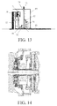
- FIGS. 11 to 18 give representations of embodiments with a dry plate clutch and wet plate brake 82 .
- FIG. 12 is a concrete design of the embodiment diagrammatically represented in FIG. 11
- FIG. 14 is a concrete design of the embodiment diagrammatically represented in FIG. 13 .
- the intermediate member is referred to as 79 and the transmission housing as 80 .
- a thrust bearing 81 Between the clutch actuator 74 and the lever of the first clutch part is positioned a thrust bearing 81 .
- the primary shaft 83 of the transmission is extended here, but made of one piece (without separate shaft extension).
- FIG. 15 represents a further variant.
- FIGS. 16 and 17 the clutch actuator 74 is displaced so that it can be actuated direct from the transmission housing.
- This requires two axial bearings and a through coupling.
- the through coupling 78 is arranged as a tooth/spline/keyed connection which projects through the connecting plate between the primary shaft and bypass transmission.
- the through coupling rotates at the same speed as the connecting plate but is slidable indeed in axial direction with respect to this connecting plate.
- FIG. 18 is again a concrete embodiment of the diagrammatic representation of FIG. 17 .
- FIGS. 19 and 20 represent embodiments with a wet plate clutch and a dry plate brake.
- 84 indicates the dry space and 85 the wet space.
- the actuation force is supported via bearing 86 .
- the embodiment represented in FIG. 19 has the advantage of the launching element (brake) being dry and the power shift element (the clutch) being wet.
- the supporting forces of the clutch and brake actuators can be directly supported on the intermediate housing part, which is advantageous.
- the primary shaft is extended.
- FIGS. 21 , 22 and 23 embodiments are represented having a wet plate clutch and a wet plate brake.
- the power shift module is constructed here as a substitute for the torque converter.
- the ratio range of the transmission can then be diminished by means of the switchable prereduction, which provides high efficiency (which the torque converter does not possess).
- the coupling (lock-up) is referred to as 90 and the brake is referred to as 91 .
- the planetary gear set has 92 as a reference numeral and the housing 93 .
- the connection to the oil pump is referred to as 94 .
- the transmission sump is referred to as 95 and 96 indicates a connection to use that very oil.
- the sump module is referred to as 97 and 98 is an electrical oil pump for lubrication and cooling of the planetary gear set.
- the oil sump of the transmission is connected to the oil sump of the power shift module.
- a partition/receptacle is installed so that the wet brake or clutch need not continuously rotate in the oil, which reduces friction losses.
- a partition is referred to as 99 to keep oil away from the brake so that the brake has less slip loss.
Landscapes
- Engineering & Computer Science (AREA)
- General Engineering & Computer Science (AREA)
- Mechanical Engineering (AREA)
- Structure Of Transmissions (AREA)
- Arrangement Of Transmissions (AREA)
- Mechanical Operated Clutches (AREA)
- Hydraulic Clutches, Magnetic Clutches, Fluid Clutches, And Fluid Joints (AREA)
Applications Claiming Priority (10)
| Application Number | Priority Date | Filing Date | Title |
|---|---|---|---|
| NL2003064 | 2009-06-22 | ||
| NL2003064 | 2009-06-22 | ||
| NL2004096 | 2010-01-14 | ||
| NL2004096 | 2010-01-14 | ||
| NL2004151 | 2010-01-26 | ||
| NL2004151 | 2010-01-26 | ||
| NL2004387A NL2004387B1 (nl) | 2009-06-22 | 2010-03-12 | Transmissiemodule voor een truck |
| NL2004387 | 2010-03-12 | ||
| NL200487 | 2010-03-12 | ||
| PCT/NL2010/000101 WO2010151113A1 (en) | 2009-06-22 | 2010-06-22 | Transmission module for a lorry |
Publications (2)
| Publication Number | Publication Date |
|---|---|
| US20120142482A1 US20120142482A1 (en) | 2012-06-07 |
| US8882625B2 true US8882625B2 (en) | 2014-11-11 |
Family
ID=45876516
Family Applications (1)
| Application Number | Title | Priority Date | Filing Date |
|---|---|---|---|
| US13/380,488 Expired - Fee Related US8882625B2 (en) | 2009-06-22 | 2010-06-22 | Transmission module for a lorry |
Country Status (6)
| Country | Link |
|---|---|
| US (1) | US8882625B2 (enExample) |
| EP (1) | EP2446171B1 (enExample) |
| JP (1) | JP5658246B2 (enExample) |
| KR (1) | KR20120030555A (enExample) |
| CN (1) | CN102648363B (enExample) |
| WO (1) | WO2010151113A1 (enExample) |
Families Citing this family (3)
| Publication number | Priority date | Publication date | Assignee | Title |
|---|---|---|---|---|
| EP2782771B1 (en) * | 2011-11-23 | 2018-09-26 | DTI Group B.V. | Flywheel module for a vehicle, as well as methods of operating the flywheel module |
| SE540703C2 (en) * | 2017-02-08 | 2018-10-16 | Scania Cv Ab | A gearbox for vehicles |
| NL2018971B1 (en) * | 2017-05-24 | 2018-12-07 | Punch Powertrain Nv | a shifting method for a transmission, a transmission system, a computer program product, and a vehicle. |
Citations (7)
| Publication number | Priority date | Publication date | Assignee | Title |
|---|---|---|---|---|
| EP0314644A2 (en) | 1987-10-26 | 1989-05-03 | SAME S.p.A. | A gearbox casing for tractors |
| US20040127320A1 (en) * | 2002-10-02 | 2004-07-01 | Jatco Ltd | Oil pressure control of transmission for vehicles |
| WO2007011212A1 (en) | 2005-07-18 | 2007-01-25 | Dti Group B.V. | Clutch usable in a vehicle drive, as well as a drive provided with the clutch |
| US7204781B2 (en) * | 2001-05-14 | 2007-04-17 | Nissan Motor Co., Ltd. | Auxiliary transmission in transmission system |
| WO2007043875A1 (en) | 2005-10-14 | 2007-04-19 | Dti Group B.V. | Vehicle with two parallel drivelines |
| WO2010101467A1 (en) | 2009-03-06 | 2010-09-10 | Dti Group B.V. | Transmission for an electric or hybrid drive |
| US20100323839A1 (en) * | 2009-06-18 | 2010-12-23 | Toyota Jidosha Kabushiki Kaisha | Forward-reverse switching device for vehicle |
Family Cites Families (5)
| Publication number | Priority date | Publication date | Assignee | Title |
|---|---|---|---|---|
| JP2002048213A (ja) * | 2000-08-01 | 2002-02-15 | Toyota Motor Corp | 無段変速機構を備えた変速機 |
| JP3870716B2 (ja) * | 2001-05-14 | 2007-01-24 | 日産自動車株式会社 | 変速機のトーショナルダンパー機構 |
| CN101189449B (zh) * | 2005-04-08 | 2012-07-25 | Dti集团有限公司 | 用于尤其是载重汽车的车辆的驱动器 |
| WO2007011211A2 (en) * | 2005-07-18 | 2007-01-25 | Dti Group B.V. | Gear module |
| CN101303073B (zh) * | 2008-06-27 | 2010-08-11 | 华南理工大学 | 一种分汇流式多挡自动变速系统 |
-
2010
- 2010-06-22 CN CN201080037519.7A patent/CN102648363B/zh not_active Expired - Fee Related
- 2010-06-22 US US13/380,488 patent/US8882625B2/en not_active Expired - Fee Related
- 2010-06-22 JP JP2012517424A patent/JP5658246B2/ja not_active Expired - Fee Related
- 2010-06-22 KR KR1020127001349A patent/KR20120030555A/ko not_active Ceased
- 2010-06-22 WO PCT/NL2010/000101 patent/WO2010151113A1/en not_active Ceased
- 2010-06-22 EP EP10745445.6A patent/EP2446171B1/en active Active
Patent Citations (7)
| Publication number | Priority date | Publication date | Assignee | Title |
|---|---|---|---|---|
| EP0314644A2 (en) | 1987-10-26 | 1989-05-03 | SAME S.p.A. | A gearbox casing for tractors |
| US7204781B2 (en) * | 2001-05-14 | 2007-04-17 | Nissan Motor Co., Ltd. | Auxiliary transmission in transmission system |
| US20040127320A1 (en) * | 2002-10-02 | 2004-07-01 | Jatco Ltd | Oil pressure control of transmission for vehicles |
| WO2007011212A1 (en) | 2005-07-18 | 2007-01-25 | Dti Group B.V. | Clutch usable in a vehicle drive, as well as a drive provided with the clutch |
| WO2007043875A1 (en) | 2005-10-14 | 2007-04-19 | Dti Group B.V. | Vehicle with two parallel drivelines |
| WO2010101467A1 (en) | 2009-03-06 | 2010-09-10 | Dti Group B.V. | Transmission for an electric or hybrid drive |
| US20100323839A1 (en) * | 2009-06-18 | 2010-12-23 | Toyota Jidosha Kabushiki Kaisha | Forward-reverse switching device for vehicle |
Also Published As
| Publication number | Publication date |
|---|---|
| KR20120030555A (ko) | 2012-03-28 |
| CN102648363A (zh) | 2012-08-22 |
| WO2010151113A1 (en) | 2010-12-29 |
| JP2012530890A (ja) | 2012-12-06 |
| EP2446171A1 (en) | 2012-05-02 |
| JP5658246B2 (ja) | 2015-01-21 |
| EP2446171B1 (en) | 2019-08-14 |
| CN102648363B (zh) | 2016-01-20 |
| US20120142482A1 (en) | 2012-06-07 |
Similar Documents
| Publication | Publication Date | Title |
|---|---|---|
| US6958028B2 (en) | Ranged dual clutch transmission for motor vehicles | |
| KR101539475B1 (ko) | 10단 자동 변속기 | |
| US9194463B2 (en) | 10-shift power train of automatic transmission for vehicle | |
| EP2649345B1 (en) | Transmission for an electric or hybrid drive mechanism | |
| US8752442B2 (en) | Multi-clutch transmission for a motor vehicle | |
| US20070238574A1 (en) | Multi-speed transmission | |
| KR20160094295A (ko) | 다단 자동 변속기 | |
| US7156768B2 (en) | Multi-stage transmission | |
| CN101568749A (zh) | 双离合器变速器 | |
| US20070202983A1 (en) | Multi-speed transmission | |
| US8870704B2 (en) | Multistage transmission | |
| US20100048345A1 (en) | Multi-stage gearbox | |
| US20110167955A1 (en) | DCT transmission utilizing a two axis chain | |
| US7186202B2 (en) | Multi-speed gearbox | |
| US8882625B2 (en) | Transmission module for a lorry | |
| US8584543B2 (en) | Drive train of a motor vehicle | |
| US7211021B2 (en) | Multi-speed gearbox | |
| US7175562B2 (en) | Multi-stage transmission | |
| KR20160094296A (ko) | 다단 자동 변속기 | |
| US7325662B2 (en) | Dry friction launch clutch for an automatic transmission and method | |
| CN103967961B (zh) | 基于行星机构的离合器及车辆变速总成 | |
| US8672795B1 (en) | Multistage transmission | |
| US20120316022A1 (en) | Transmission system for a vehicle | |
| WO2012101400A1 (en) | Rotary transmission | |
| US20180306280A1 (en) | Planetary Power-Shift Multi-Stage Transmission, in Particular for an Internal Combustion Engine and/or Electric Motor Drive of a Motor Vehicle |
Legal Events
| Date | Code | Title | Description |
|---|---|---|---|
| AS | Assignment |
Owner name: DTI GROUP B.V., NETHERLANDS Free format text: ASSIGNMENT OF ASSIGNORS INTEREST;ASSIGNORS:VAN DRUTEN, ROELL MARIE;VROEMEN, BAS GERARD;SERRARENS, ALEXANDER FRANCISCUS ANITA;REEL/FRAME:027750/0028 Effective date: 20120209 |
|
| STCF | Information on status: patent grant |
Free format text: PATENTED CASE |
|
| MAFP | Maintenance fee payment |
Free format text: PAYMENT OF MAINTENANCE FEE, 4TH YEAR, LARGE ENTITY (ORIGINAL EVENT CODE: M1551) Year of fee payment: 4 |
|
| FEPP | Fee payment procedure |
Free format text: MAINTENANCE FEE REMINDER MAILED (ORIGINAL EVENT CODE: REM.); ENTITY STATUS OF PATENT OWNER: LARGE ENTITY |
|
| LAPS | Lapse for failure to pay maintenance fees |
Free format text: PATENT EXPIRED FOR FAILURE TO PAY MAINTENANCE FEES (ORIGINAL EVENT CODE: EXP.); ENTITY STATUS OF PATENT OWNER: LARGE ENTITY |
|
| STCH | Information on status: patent discontinuation |
Free format text: PATENT EXPIRED DUE TO NONPAYMENT OF MAINTENANCE FEES UNDER 37 CFR 1.362 |
|
| FP | Lapsed due to failure to pay maintenance fee |
Effective date: 20221111 |