EP2446171B1 - Transmission module for a lorry - Google Patents
Transmission module for a lorry Download PDFInfo
- Publication number
- EP2446171B1 EP2446171B1 EP10745445.6A EP10745445A EP2446171B1 EP 2446171 B1 EP2446171 B1 EP 2446171B1 EP 10745445 A EP10745445 A EP 10745445A EP 2446171 B1 EP2446171 B1 EP 2446171B1
- Authority
- EP
- European Patent Office
- Prior art keywords
- transmission
- clutch
- module
- input
- output
- Prior art date
- Legal status (The legal status is an assumption and is not a legal conclusion. Google has not performed a legal analysis and makes no representation as to the accuracy of the status listed.)
- Active
Links
Images


Classifications
-
- F—MECHANICAL ENGINEERING; LIGHTING; HEATING; WEAPONS; BLASTING
- F16—ENGINEERING ELEMENTS AND UNITS; GENERAL MEASURES FOR PRODUCING AND MAINTAINING EFFECTIVE FUNCTIONING OF MACHINES OR INSTALLATIONS; THERMAL INSULATION IN GENERAL
- F16H—GEARING
- F16H37/00—Combinations of mechanical gearings, not provided for in groups F16H1/00 - F16H35/00
- F16H37/02—Combinations of mechanical gearings, not provided for in groups F16H1/00 - F16H35/00 comprising essentially only toothed or friction gearings
- F16H37/04—Combinations of toothed gearings only
- F16H37/042—Combinations of toothed gearings only change gear transmissions in group arrangement
- F16H37/046—Combinations of toothed gearings only change gear transmissions in group arrangement with an additional planetary gear train, e.g. creep gear, overdrive
-
- F—MECHANICAL ENGINEERING; LIGHTING; HEATING; WEAPONS; BLASTING
- F16—ENGINEERING ELEMENTS AND UNITS; GENERAL MEASURES FOR PRODUCING AND MAINTAINING EFFECTIVE FUNCTIONING OF MACHINES OR INSTALLATIONS; THERMAL INSULATION IN GENERAL
- F16H—GEARING
- F16H37/00—Combinations of mechanical gearings, not provided for in groups F16H1/00 - F16H35/00
- F16H37/02—Combinations of mechanical gearings, not provided for in groups F16H1/00 - F16H35/00 comprising essentially only toothed or friction gearings
- F16H37/04—Combinations of toothed gearings only
- F16H37/042—Combinations of toothed gearings only change gear transmissions in group arrangement
- F16H37/043—Combinations of toothed gearings only change gear transmissions in group arrangement without gears having orbital motion
-
- B—PERFORMING OPERATIONS; TRANSPORTING
- B60—VEHICLES IN GENERAL
- B60Y—INDEXING SCHEME RELATING TO ASPECTS CROSS-CUTTING VEHICLE TECHNOLOGY
- B60Y2200/00—Type of vehicle
- B60Y2200/10—Road Vehicles
- B60Y2200/14—Trucks; Load vehicles, Busses
-
- F—MECHANICAL ENGINEERING; LIGHTING; HEATING; WEAPONS; BLASTING
- F16—ENGINEERING ELEMENTS AND UNITS; GENERAL MEASURES FOR PRODUCING AND MAINTAINING EFFECTIVE FUNCTIONING OF MACHINES OR INSTALLATIONS; THERMAL INSULATION IN GENERAL
- F16H—GEARING
- F16H3/00—Toothed gearings for conveying rotary motion with variable gear ratio or for reversing rotary motion
- F16H3/02—Toothed gearings for conveying rotary motion with variable gear ratio or for reversing rotary motion without gears having orbital motion
- F16H3/08—Toothed gearings for conveying rotary motion with variable gear ratio or for reversing rotary motion without gears having orbital motion exclusively or essentially with continuously meshing gears, that can be disengaged from their shafts
- F16H2003/0818—Toothed gearings for conveying rotary motion with variable gear ratio or for reversing rotary motion without gears having orbital motion exclusively or essentially with continuously meshing gears, that can be disengaged from their shafts comprising means for power-shifting
-
- F—MECHANICAL ENGINEERING; LIGHTING; HEATING; WEAPONS; BLASTING
- F16—ENGINEERING ELEMENTS AND UNITS; GENERAL MEASURES FOR PRODUCING AND MAINTAINING EFFECTIVE FUNCTIONING OF MACHINES OR INSTALLATIONS; THERMAL INSULATION IN GENERAL
- F16H—GEARING
- F16H2200/00—Transmissions for multiple ratios
- F16H2200/003—Transmissions for multiple ratios characterised by the number of forward speeds
- F16H2200/0034—Transmissions for multiple ratios characterised by the number of forward speeds the gear ratios comprising two forward speeds
-
- F—MECHANICAL ENGINEERING; LIGHTING; HEATING; WEAPONS; BLASTING
- F16—ENGINEERING ELEMENTS AND UNITS; GENERAL MEASURES FOR PRODUCING AND MAINTAINING EFFECTIVE FUNCTIONING OF MACHINES OR INSTALLATIONS; THERMAL INSULATION IN GENERAL
- F16H—GEARING
- F16H3/00—Toothed gearings for conveying rotary motion with variable gear ratio or for reversing rotary motion
- F16H3/44—Toothed gearings for conveying rotary motion with variable gear ratio or for reversing rotary motion using gears having orbital motion
- F16H3/46—Gearings having only two central gears, connected by orbital gears
- F16H3/48—Gearings having only two central gears, connected by orbital gears with single orbital gears or pairs of rigidly-connected orbital gears
- F16H3/52—Gearings having only two central gears, connected by orbital gears with single orbital gears or pairs of rigidly-connected orbital gears comprising orbital spur gears
- F16H3/54—Gearings having only two central gears, connected by orbital gears with single orbital gears or pairs of rigidly-connected orbital gears comprising orbital spur gears one of the central gears being internally toothed and the other externally toothed
-
- F—MECHANICAL ENGINEERING; LIGHTING; HEATING; WEAPONS; BLASTING
- F16—ENGINEERING ELEMENTS AND UNITS; GENERAL MEASURES FOR PRODUCING AND MAINTAINING EFFECTIVE FUNCTIONING OF MACHINES OR INSTALLATIONS; THERMAL INSULATION IN GENERAL
- F16H—GEARING
- F16H3/00—Toothed gearings for conveying rotary motion with variable gear ratio or for reversing rotary motion
- F16H3/44—Toothed gearings for conveying rotary motion with variable gear ratio or for reversing rotary motion using gears having orbital motion
- F16H3/46—Gearings having only two central gears, connected by orbital gears
- F16H3/48—Gearings having only two central gears, connected by orbital gears with single orbital gears or pairs of rigidly-connected orbital gears
- F16H3/52—Gearings having only two central gears, connected by orbital gears with single orbital gears or pairs of rigidly-connected orbital gears comprising orbital spur gears
- F16H3/56—Gearings having only two central gears, connected by orbital gears with single orbital gears or pairs of rigidly-connected orbital gears comprising orbital spur gears both central gears being sun gears
-
- Y—GENERAL TAGGING OF NEW TECHNOLOGICAL DEVELOPMENTS; GENERAL TAGGING OF CROSS-SECTIONAL TECHNOLOGIES SPANNING OVER SEVERAL SECTIONS OF THE IPC; TECHNICAL SUBJECTS COVERED BY FORMER USPC CROSS-REFERENCE ART COLLECTIONS [XRACs] AND DIGESTS
- Y10—TECHNICAL SUBJECTS COVERED BY FORMER USPC
- Y10T—TECHNICAL SUBJECTS COVERED BY FORMER US CLASSIFICATION
- Y10T74/00—Machine element or mechanism
- Y10T74/19—Gearing
- Y10T74/19019—Plural power paths from prime mover
Definitions
- the invention relates to a transmission module for a vehicle, more particularly a lorry, comprising a clutch that includes two clutch parts which can be mutually coupled, a first clutch part of which being capable of coupling to a drive source of a vehicle and the second clutch part of which being capable of coupling to an input shaft of a transmission of the vehicle.
- a transmission module of this type is known from EP0314644A2 .
- the transmission module according to the invention it is possible by operating the clutch and further clutch to switch between a gear ratio of one to one and the gear ratio of the transmission of the part module without interruption of the torque transfer.
- the transmission module according to the invention when used in a lorry, it is possible to create twice as many gear ratios as without this transmission module.
- the further clutch can be unloaded or synchronised so that it can be opened or closed more easily.
- the further clutch can be designed such that it cannot dissipate any significant power in relation to the clutch.
- the further clutch is preferably arranged as a claw clutch or synchromesh or as a friction clutch which cannot dissipate any significant power in relation to the clutch.
- the transmission may comprise at least one switchable transmission which includes gear wheels as well as clutch means, such as a claw clutch or a synchromesh, for coupling at least one of the gear wheels to a shaft it is located on.
- clutch means such as a claw clutch or a synchromesh
- the transmission of the vehicle preferably comprises a continuously variable transmission element such as a push belt or a chain variator.
- the clutch is preferably arranged such that if it is not operated, it is closed (normally closed). Furthermore, the further clutch may be arranged such that if it is not operated, it is open (normally open).
- the clutch is preferably operated by a pull actuator which pulls at a diaphragm spring of the clutch to open the clutch, or by a push actuator which pushes a diaphragm spring of the clutch to open the clutch.
- the clutch is preferably arranged as a dry plate friction clutch and the further clutch is arranged as a dry plate friction clutch, or the clutch is arranged as a wet plate friction clutch and the further clutch is arranged as a wet plate friction clutch.
- An embodiment of the transmission module is that the transmission is formed by a bypass transmission with at least three rotational members of which a first rotational member is connected to the input, a second rotational member is connected to the output and the third rotational member can be coupled to the firm object via the further clutch or brake.
- the firm object is for example a transmission housing.
- the first rotational member is preferably formed by a ring gear
- the second rotational member is formed by a planet gear carrier on which planet gears are bearing mounted
- the third rotational member is formed by a sun gear, or the first rotational member by a sun gear, the second rotational member by a second sun gear and the third rotational member by a carrier on which planet gears are bearing mounted.
- a torsion damper is positioned between the first rotational member and a clutch cover forming part of the first clutch part.
- an intermediate housing part is positioned between the clutch and a transmission housing of the transmission.
- a rotation seal is present between the first rotational member and the intermediate housing part. Furthermore, preferably a rotation seal is present between the first rotational member and a primary shaft of the transmission.
- connection between the clutch cover and the first rotational member preferably passes underneath the clutch actuator through a connecting sleeve.
- first and the third rotational members are bearing-mounted directly on the primary shaft of the transmission.
- the transmission comprises two partial transmissions each having an input and an output shaft, of which the input shaft of a first one of the partial transmissions is connected to the input and the output shaft of the second one of the partial transmissions is connected to the output and the output shaft of the first partial transmission and the input shaft of the second partial transmission can be coupled to each other by means of the further clutch.
- the partial transmissions may be for example gear trains, chain transmissions or belt transmissions.
- a further embodiment of the transmission module according to the invention is characterised in that the first partial transmission is accelerating and the second partial transmission is retarding in the direction of the output. As a result, the torque that is transferred by the further clutch during operation is reduced, so that the further clutch is loaded to a lesser extent.
- a still further embodiment of the transmission module according to the invention is characterised in that the gear ratio of the part module, defined by the r.p.m. during operation of the input divided by the r.p.m. of the output, is greater than 1.
- the gear ratio of the part module is greater than or equal to 1.3.
- the part module may be arranged as a separate module which can be built-in in the existing drive train of a lorry.
- the input and the output of the part module are preferably provided with teeth for coupling to the first clutch part and/or drive source or the input shaft of the transmission of the lorry and/or the second clutch part respectively.
- the teeth may be for example splines.
- the output is then preferably formed by an extension shaft which is connected to the second clutch part. This extension shaft is used for extending the input shaft of the transmission of the lorry when the transmission module is used in the lorry, so that this input shaft can be connected to the second clutch part.
- operating means for operating the clutch and/or further operating means for operating the further clutch form part of the part module.
- the operating means and the further operating mean are preferably fed with compressed air. This air supply is preferably led via the intermediate housing part to the operating means and the further operating means.
- the disclosure also relates to a part module which can be applied to the transmission module according to the invention.
- the further clutch may be unloaded or synchronised so that it can be opened or closed in a simple manner.
- the vehicle By operating (actuating) the further clutch the vehicle may be started out in forward or backward direction.
- the vehicle By operating (actuating) the further clutch the vehicle may be launched in forward or backward direction and by then operating (actuating) the clutch it is possible to shift to a higher gear without torque interruption of the wheels of the vehicle.
- the lorry 1 has a combustion engine 3 which is connected via the transmission module 5 to the input shaft 7 of a for example automatic transmission 9 with switchable drives.
- the output shaft 11 of the transmission 9 is connected to the wheels 15 of the lorry by means of a differential 13.
- the transmission module 5 comprises a clutch 17 having two clutch parts 17A and 17B that can be coupled to each other.
- the transmission module 5 further comprises a part module 19 which has an input 21 and an output 23.
- the input 21 is coupled to the clutch part 17A and the output 23 is coupled to the clutch part 17B.
- the part module 19 has a bypass transmission 25 with three rotational members of which a first rotational member 27 is connected to the input 21, a second rotational member 29 is connected to the output 23 and the third rotational member 31 can be coupled via a brake 33 to the firm object 35 which is formed for example by the housing of the transmission.
- the bypass transmission 25 is made such that the directions of rotation of the first and second rotational members 27 and 29 are equal to each other.
- the brake 33 cannot dissipate significant power in relation to the clutch 17.
- Fig. 2 gives a diagrammatic representation of a second embodiment of the transmission module according to the invention used in a lorry. All parts that are equal to those of the first embodiment are referred to by like reference numerals.
- the part module 39 of this transmission module 37 has two partial transmissions 41 and 43 each having an input shaft 45, 49 and an output shaft 47, 51.
- the partial transmissions are formed by gear pairs.
- the input shaft 45 is connected to the input 21 and the output shaft 51 is connected to the output 23.
- the output shaft 47 and the input shaft 49 can be coupled to each other by means of a further clutch 53.
- the further clutch 53 cannot dissipate significant power in relation to the clutch 17 and is arranged as a claw clutch or synchromesh or as a friction clutch or friction brake which cannot dissipate significant power in relation to the clutch.
- the partial transmission 41 has an accelerating effect and the partial transmission 43 has a retarding effect in the direction of the output 23.
- the gear ratio of the transmission modules 5 and 37 defined by the r.p.m. during operation of the input 21 divided by the r.p.m. of the output 23, is approximately 1.3.
- Fig. 3 gives a diagrammatic representation of a constructive embodiment of the transmission module represented in Fig. 1 .
- the clutch 17 provided in this embodiment is a wet plate clutch.
- Fig. 4 gives a diagrammatic representation of another constructive embodiment of the transmission module represented in Fig. 1 .
- the clutch 17 is provided as a dry plate clutch.
- the input is constituted by a connecting plate 55 which is coupled to the clutch part 17A formed by a clutch cover via spline teeth 57 or other mechanical connection.
- the output is formed by an extension shaft 59 which is connected to the second clutch part 17B which is formed by a clutch plate also via spline connection 61 or other mechanical connection, and is connected to the input shaft 7 of the transmission 9 via spline connection 63.
- the part module 19 comprises operating means for operating the clutch 17. These operating means are formed by an actuator 65. Further operating means too (not shown) for operating the brake form part of the part module 19.
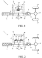
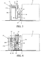
- Fig. 5 gives a diagrammatic representation of a constructive embodiment of the transmission module represented in Fig. 2 .
- the clutch 17 is again arranged as a wet plate clutch.
- Fig. 6 gives a diagrammatic representation of another constructive embodiment of the transmission module represented in Fig. 2 . All parts that are equal to those of the first embodiment represented in Fig. 4 are referred to by like reference numerals.
- the clutch 17 is here arranged as a dry plate clutch.
- the further operating means (but now for the further clutch) which form part of the part module are not represented here either.
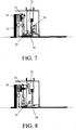
- Figs. 7 to 10 give representations of embodiments with a dry plate clutch and a dry plate brake.
- the embodiment represented in Fig. 7 comprises a specific connection to the bypass transmission and a specific configuration of the seals (pellets).
- 71 is used to refer to the connection of the connecting plate 72 to torsion spring and the clutch cover.
- the brake actuator and clutch actuator are referred to by 73 and 74 respectively, the bypass transmission by 75 and the clutch plate by 76.
- the input shaft is connected to the clutch plate via a spline connection 77.
- the bypass transmission is positioned inside the clutch housing.
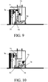
- Figs. 9 and 10 give representations of embodiments in which the clutch actuator is displaced so that it can be actuated direct from the transmission housing. This requires two axial bearings and a through coupling.
- the through coupling is arranged as a tooth/spline/keyed connection which projects through the connecting plate between the primary shaft and the bypass transmission.
- the through coupling 78 rotates at the same speed as the connecting plate but is slidable indeed in axial direction with respect to this connecting plate.
- Figs. 11 to 18 give representations of embodiments with a dry plate clutch and wet plate brake 82.
- Fig. 12 is a concrete design of the embodiment diagrammatically represented in Fig. 11 and
- Fig. 14 is a concrete design of the embodiment diagrammatically represented in Fig. 13 .
- the intermediate member is referred to as 79 and the transmission housing as 80.
- a thrust bearing 81 Between the clutch actuator 74 and the lever of the first clutch part is positioned a thrust bearing 81.
- the primary shaft 83 of the transmission is extended here, but made of one piece (without separate shaft extension).
- Fig. 15 represents a further variant.
- Figs. 16 and 17 the clutch actuator 74 is displaced so that it can be actuated direct from the transmission housing.
- This requires two axial bearings and a through coupling.
- the through coupling 78 is arranged as a tooth/spline/keyed connection which projects through the connecting plate between the primary shaft and bypass transmission.
- the through coupling rotates at the same speed as the connecting plate but is slidable indeed in axial direction with respect to this connecting plate.
- Fig. 18 is again a concrete embodiment of the diagrammatic representation of Fig. 17 .
- Figs. 19 and 20 represent embodiments with a wet plate clutch and a dry plate brake.
- 84 indicates the dry space and 85 the wet space.
- the actuation force is supported via bearing 86.
- the embodiment represented in Fig. 19 has the advantage of the launching element (brake) being dry and the power shift element (the clutch) being wet.
- the supporting forces of the clutch and brake actuators can be directly supported on the intermediate housing part, which is advantageous.
- the primary shaft is extended.
- Figs. 21, 22 and 23 embodiments are represented having a wet plate clutch and a wet plate brake.
- the power shift module is constructed here as a substitute for the torque converter.
- the ratio range of the transmission can then be diminished by means of the switchable prereduction, which provides high efficiency (which the torque converter does not possess).
- the coupling (lock-up) is referred to as 90 and the brake is referred to as 91.
- the planetary gear set has 92 as a reference numeral and the housing 93.
- the connection to the oil pump is referred to as 94.
- the transmission sump is referred to as 95 and 96 indicates a connection to use that very oil.
- the sump module is referred to as 97 and 98 is an electrical oil pump for lubrication and cooling of the planetary gear set.
- the oil sump of the transmission is connected to the oil sump of the power shift module.
- oil sump a partition/receptacle is installed so that the wet brake or clutch need not continuously rotate in the oil, which reduces friction losses.
- a partition is referred to as 99 to keep oil away from the brake so that the brake has less slip loss.
Description
- The invention relates to a transmission module for a vehicle, more particularly a lorry, comprising a clutch that includes two clutch parts which can be mutually coupled, a first clutch part of which being capable of coupling to a drive source of a vehicle and the second clutch part of which being capable of coupling to an input shaft of a transmission of the vehicle.
- A transmission module of this type is known from
EP0314644A2 . - It is an object of the invention to improve the known transmission module. This object is solved by a transmission module according to
claim 1. The dependent claims concern particular embodiments of the invention as defined inclaim 1. - With the transmission module according to the invention it is possible by operating the clutch and further clutch to switch between a gear ratio of one to one and the gear ratio of the transmission of the part module without interruption of the torque transfer. As a result, with the transmission module according to the invention when used in a lorry, it is possible to create twice as many gear ratios as without this transmission module.
- Advantages of the transmission according to the invention over the known transmission are the following:
- The module allows for shifting with torque transfer from the highest gear to a lower gear. This is particularly important when in the highest gear (prise direct) one has to shift down because a slight slope is to be taken that requires more power.
- The module also allows for an extra gear to be created under the lowest gear. This extra low gear allows for changing the end reduction to the wheels such that it is possible to drive with lower r.p.m., which reduces fuel consumption.
- Power shifts are possible between the 1-2, 3-4 and 5-6 gear shifts.
- By operating the clutch, the further clutch can be unloaded or synchronised so that it can be opened or closed more easily.
- In order to keep the part module cost effective, the further clutch can be designed such that it cannot dissipate any significant power in relation to the clutch. The further clutch is preferably arranged as a claw clutch or synchromesh or as a friction clutch which cannot dissipate any significant power in relation to the clutch.
- Not claimed is that the transmission may comprise at least one switchable transmission which includes gear wheels as well as clutch means, such as a claw clutch or a synchromesh, for coupling at least one of the gear wheels to a shaft it is located on.
- The transmission of the vehicle preferably comprises a continuously variable transmission element such as a push belt or a chain variator.
- The clutch is preferably arranged such that if it is not operated, it is closed (normally closed). Furthermore, the further clutch may be arranged such that if it is not operated, it is open (normally open).
- The clutch is preferably operated by a pull actuator which pulls at a diaphragm spring of the clutch to open the clutch, or by a push actuator which pushes a diaphragm spring of the clutch to open the clutch.
- The clutch is preferably arranged as a dry plate friction clutch and the further clutch is arranged as a dry plate friction clutch, or the clutch is arranged as a wet plate friction clutch and the further clutch is arranged as a wet plate friction clutch.
- An embodiment of the transmission module, not claimed, is that the transmission is formed by a bypass transmission with at least three rotational members of which a first rotational member is connected to the input, a second rotational member is connected to the output and the third rotational member can be coupled to the firm object via the further clutch or brake. The firm object is for example a transmission housing. The following are aspects of the above described embodiment, not claimed.
- The first rotational member is preferably formed by a ring gear, the second rotational member is formed by a planet gear carrier on which planet gears are bearing mounted and the third rotational member is formed by a sun gear, or the first rotational member by a sun gear, the second rotational member by a second sun gear and the third rotational member by a carrier on which planet gears are bearing mounted.
- Preferably a torsion damper is positioned between the first rotational member and a clutch cover forming part of the first clutch part.
- Furthermore, preferably an intermediate housing part is positioned between the clutch and a transmission housing of the transmission.
- Preferably a rotation seal is present between the first rotational member and the intermediate housing part. Furthermore, preferably a rotation seal is present between the first rotational member and a primary shaft of the transmission.
- The connection between the clutch cover and the first rotational member preferably passes underneath the clutch actuator through a connecting sleeve.
- Furthermore, preferably the first and the third rotational members are bearing-mounted directly on the primary shaft of the transmission.
- Another embodiment of the transmission module which forms an alternative to the embodiments described above in which the transmission is formed by a bypass transmission is that the transmission comprises two partial transmissions each having an input and an output shaft, of which the input shaft of a first one of the partial transmissions is connected to the input and the output shaft of the second one of the partial transmissions is connected to the output and the output shaft of the first partial transmission and the input shaft of the second partial transmission can be coupled to each other by means of the further clutch. The partial transmissions may be for example gear trains, chain transmissions or belt transmissions.
- A further embodiment of the transmission module according to the invention is characterised in that the first partial transmission is accelerating and the second partial transmission is retarding in the direction of the output. As a result, the torque that is transferred by the further clutch during operation is reduced, so that the further clutch is loaded to a lesser extent.
- A still further embodiment of the transmission module according to the invention is characterised in that the gear ratio of the part module, defined by the r.p.m. during operation of the input divided by the r.p.m. of the output, is greater than 1. Preferably the gear ratio of the part module is greater than or equal to 1.3.
- The part module may be arranged as a separate module which can be built-in in the existing drive train of a lorry. For this purpose, the input and the output of the part module are preferably provided with teeth for coupling to the first clutch part and/or drive source or the input shaft of the transmission of the lorry and/or the second clutch part respectively. The teeth may be for example splines. The output is then preferably formed by an extension shaft which is connected to the second clutch part. This extension shaft is used for extending the input shaft of the transmission of the lorry when the transmission module is used in the lorry, so that this input shaft can be connected to the second clutch part.
- Preferably, operating means for operating the clutch and/or further operating means for operating the further clutch form part of the part module. The operating means and the further operating mean are preferably fed with compressed air. This air supply is preferably led via the intermediate housing part to the operating means and the further operating means.
- The disclosure also relates to a part module which can be applied to the transmission module according to the invention.
- By operating (actuating) the clutch, the further clutch may be unloaded or synchronised so that it can be opened or closed in a simple manner.
- By operating (actuating) the clutch and further clutch it is possible to switch gears without torque interruption between 1:1 and a transmission between the drive shaft and the input shaft of the transmission.
- By operating (actuating) the further clutch the vehicle may be started out in forward or backward direction.
- By operating (actuating) the further clutch the vehicle may be launched in forward or backward direction and by then operating (actuating) the clutch it is possible to shift to a higher gear without torque interruption of the wheels of the vehicle.
- The invention will be described below in more detail based on examples of embodiments of the transmission module according to the invention represented in the drawing, whereby only
Fig. 2 ,5 and 6 show transmission modules falling within the wording ofclaim 1. -
Fig. 1 gives a diagrammatic representation of a first embodiment not falling within the wording ofclaim 1, used in a lorry; -
Fig. 2 gives a diagrammatic representation of a first embodiment of the transmission module according to the invention used in a lorry; -
Fig. 3 gives a diagrammatic representation of a constructive embodiment of the transmission module represented inFig. 1 provided with a wet plate clutch; -
Fig. 4 gives a diagrammatic representation of the transmission module represented inFig. 1 provided with a dry plate clutch; -
Fig. 5 gives a diagrammatic representation of a constructive embodiment of the transmission module represented inFig. 2 provided with a wet plate clutch; -
Fig. 6 gives a diagrammatic representation of a constructive embodiment of the transmission module represented inFig. 2 provided with a dry plate clutch; and -
Figs. 7 to 23 give representations of further embodiments not falling within the wording ofclaim 1. - According to
Fig.1 , thelorry 1 has acombustion engine 3 which is connected via thetransmission module 5 to theinput shaft 7 of a for exampleautomatic transmission 9 with switchable drives. Theoutput shaft 11 of thetransmission 9 is connected to thewheels 15 of the lorry by means of a differential 13. - The
transmission module 5 comprises a clutch 17 having twoclutch parts transmission module 5 further comprises apart module 19 which has aninput 21 and anoutput 23. Theinput 21 is coupled to theclutch part 17A and theoutput 23 is coupled to theclutch part 17B. - The
part module 19 has abypass transmission 25 with three rotational members of which a firstrotational member 27 is connected to theinput 21, a secondrotational member 29 is connected to theoutput 23 and the thirdrotational member 31 can be coupled via abrake 33 to thefirm object 35 which is formed for example by the housing of the transmission. Thebypass transmission 25 is made such that the directions of rotation of the first and secondrotational members brake 33 cannot dissipate significant power in relation to the clutch 17. -
Fig. 2 gives a diagrammatic representation of a second embodiment of the transmission module according to the invention used in a lorry. All parts that are equal to those of the first embodiment are referred to by like reference numerals. - The
part module 39 of thistransmission module 37 has twopartial transmissions input shaft output shaft input shaft 45 is connected to theinput 21 and theoutput shaft 51 is connected to theoutput 23. Theoutput shaft 47 and theinput shaft 49 can be coupled to each other by means of afurther clutch 53. The further clutch 53 cannot dissipate significant power in relation to the clutch 17 and is arranged as a claw clutch or synchromesh or as a friction clutch or friction brake which cannot dissipate significant power in relation to the clutch. Thepartial transmission 41 has an accelerating effect and thepartial transmission 43 has a retarding effect in the direction of theoutput 23. - The gear ratio of the
transmission modules input 21 divided by the r.p.m. of theoutput 23, is approximately 1.3. -
Fig. 3 gives a diagrammatic representation of a constructive embodiment of the transmission module represented inFig. 1 . The clutch 17 provided in this embodiment is a wet plate clutch. -
Fig. 4 gives a diagrammatic representation of another constructive embodiment of the transmission module represented inFig. 1 . Herein the clutch 17 is provided as a dry plate clutch. The input is constituted by a connectingplate 55 which is coupled to theclutch part 17A formed by a clutch cover viaspline teeth 57 or other mechanical connection.. The output is formed by anextension shaft 59 which is connected to the secondclutch part 17B which is formed by a clutch plate also viaspline connection 61 or other mechanical connection, and is connected to theinput shaft 7 of thetransmission 9 viaspline connection 63. - The
part module 19 comprises operating means for operating the clutch 17. These operating means are formed by anactuator 65. Further operating means too (not shown) for operating the brake form part of thepart module 19. -
Fig. 5 gives a diagrammatic representation of a constructive embodiment of the transmission module represented inFig. 2 . The clutch 17 is again arranged as a wet plate clutch. -
Fig. 6 gives a diagrammatic representation of another constructive embodiment of the transmission module represented inFig. 2 . All parts that are equal to those of the first embodiment represented inFig. 4 are referred to by like reference numerals. The clutch 17 is here arranged as a dry plate clutch. The further operating means (but now for the further clutch) which form part of the part module are not represented here either. -
Figs. 7 to 10 give representations of embodiments with a dry plate clutch and a dry plate brake. The embodiment represented inFig. 7 comprises a specific connection to the bypass transmission and a specific configuration of the seals (pellets). 71 is used to refer to the connection of the connectingplate 72 to torsion spring and the clutch cover. The brake actuator and clutch actuator are referred to by 73 and 74 respectively, the bypass transmission by 75 and the clutch plate by 76. The input shaft is connected to the clutch plate via aspline connection 77. InFig. 8 the bypass transmission is positioned inside the clutch housing. -
Figs. 9 and 10 give representations of embodiments in which the clutch actuator is displaced so that it can be actuated direct from the transmission housing. This requires two axial bearings and a through coupling. The through coupling is arranged as a tooth/spline/keyed connection which projects through the connecting plate between the primary shaft and the bypass transmission. The throughcoupling 78 rotates at the same speed as the connecting plate but is slidable indeed in axial direction with respect to this connecting plate. -
Figs. 11 to 18 give representations of embodiments with a dry plate clutch andwet plate brake 82.Fig. 12 is a concrete design of the embodiment diagrammatically represented inFig. 11 andFig. 14 is a concrete design of the embodiment diagrammatically represented inFig. 13 . Herein the intermediate member is referred to as 79 and the transmission housing as 80. Between theclutch actuator 74 and the lever of the first clutch part is positioned athrust bearing 81. Theprimary shaft 83 of the transmission is extended here, but made of one piece (without separate shaft extension).Fig. 15 represents a further variant. - In the embodiments represented in
Figs. 16 and17 theclutch actuator 74 is displaced so that it can be actuated direct from the transmission housing. This requires two axial bearings and a through coupling. The throughcoupling 78 is arranged as a tooth/spline/keyed connection which projects through the connecting plate between the primary shaft and bypass transmission. The through coupling rotates at the same speed as the connecting plate but is slidable indeed in axial direction with respect to this connecting plate.Fig. 18 is again a concrete embodiment of the diagrammatic representation ofFig. 17 . -
Figs. 19 and 20 represent embodiments with a wet plate clutch and a dry plate brake. 84 indicates the dry space and 85 the wet space. The actuation force is supported viabearing 86. The embodiment represented inFig. 19 has the advantage of the launching element (brake) being dry and the power shift element (the clutch) being wet. The supporting forces of the clutch and brake actuators can be directly supported on the intermediate housing part, which is advantageous. In the embodiment represented inFig. 20 the primary shaft is extended. - In
Figs. 21, 22 and23 embodiments are represented having a wet plate clutch and a wet plate brake. The power shift module is constructed here as a substitute for the torque converter. The ratio range of the transmission can then be diminished by means of the switchable prereduction, which provides high efficiency (which the torque converter does not possess). The coupling (lock-up) is referred to as 90 and the brake is referred to as 91. The planetary gear set has 92 as a reference numeral and thehousing 93. The connection to the oil pump is referred to as 94. InFig. 22 the transmission sump is referred to as 95 and 96 indicates a connection to use that very oil. The sump module is referred to as 97 and 98 is an electrical oil pump for lubrication and cooling of the planetary gear set. The oil sump of the transmission is connected to the oil sump of the power shift module. In the power shift module oil sump a partition/receptacle is installed so that the wet brake or clutch need not continuously rotate in the oil, which reduces friction losses. InFig. 23 a partition is referred to as 99 to keep oil away from the brake so that the brake has less slip loss. - Albeit the invention has been described in the foregoing based on the drawings, it should be observed that the invention is not by any manner or means restricted to the embodiment shown in the drawings.
Claims (6)
- A transmission module (37) for a vehicle (1) comprising a clutch (17) that includes two clutch parts (17A,17B) which can be mutually coupled, a first clutch part (17A) of which being capable of coupling to a drive source (3) of the vehicle (1) and the second clutch part (17B) being capable of coupling to an input shaft (7) of a transmission (9) of the vehicle, wherein the transmission module (37) furthermore comprises a part module (39) which has an input (21) and an output (23), which part module (39) comprises a transmission (41,43) of the part module (39) as well as a further clutch (53) connected to the transmission (41, 43) of the part module (39), the input (21) of the part module (39) being coupled to the first clutch part (17A) and being capable of coupling to the drive source of the vehicle, and the output (23) of the part module (39) being coupled to the second clutch part (17B) and being capable of coupling to the input shaft (7) of the transmission (9) of the vehicle, and the transmission (41,43) of the part module (39) being arranged such that the directions of rotation of the input and output shafts (21,23) of the part module (39) are equal to each other, characterised in that the transmission (41,43) of the part module (39) comprises two partial transmissions (41,43) each having an input and an output shaft (45,49;47,51), of which the input shaft (45) of a first one (41) of the partial transmissions (41,43) is connected to the input (21) of the part module (39) and the output shaft (51) of the second partial transmission (43) is connected to the output (23) of the part module (39) and the output shaft (47) of the first partial transmission (41) and the input shaft (49) of the second partial transmission (43) can be coupled to each other by means of the further clutch (53).
- A transmission module as claimed in claim 1, characterised in that the transmission (9) of the vehicle comprises at least one switchable transmission which includes gear wheels as well as clutch means, such as a claw clutch or a synchromesh, for coupling at least one of the gear wheels to a shaft it is located on.
- A transmission module as claimed in claim 1 or 2, characterised in that the transmission (9) of the vehicle comprises a continuously variable transmission element such as a push belt or a chain variator.
- A transmission module as claimed in any one of the preceding claims, characterised in that the clutch (17) is arranged such that if it is not operated, it is closed .
- A transmission module as claimed in any one of the preceding claims, characterised in that the further clutch (53) is arranged such that if it is not operated, it is open.
- A transmission module as claimed in claim 1, characterised in that the first partial transmission (41) is accelerating and the second partial transmission (43) is retarding in the direction of the output (23).
Applications Claiming Priority (5)
| Application Number | Priority Date | Filing Date | Title |
|---|---|---|---|
| NL2003064 | 2009-06-22 | ||
| NL2004096 | 2010-01-14 | ||
| NL2004151 | 2010-01-26 | ||
| NL2004387A NL2004387B1 (en) | 2009-06-22 | 2010-03-12 | Transmission module for a truck |
| PCT/NL2010/000101 WO2010151113A1 (en) | 2009-06-22 | 2010-06-22 | Transmission module for a lorry |
Publications (2)
| Publication Number | Publication Date |
|---|---|
| EP2446171A1 EP2446171A1 (en) | 2012-05-02 |
| EP2446171B1 true EP2446171B1 (en) | 2019-08-14 |
Family
ID=45876516
Family Applications (1)
| Application Number | Title | Priority Date | Filing Date |
|---|---|---|---|
| EP10745445.6A Active EP2446171B1 (en) | 2009-06-22 | 2010-06-22 | Transmission module for a lorry |
Country Status (6)
| Country | Link |
|---|---|
| US (1) | US8882625B2 (en) |
| EP (1) | EP2446171B1 (en) |
| JP (1) | JP5658246B2 (en) |
| KR (1) | KR20120030555A (en) |
| CN (1) | CN102648363B (en) |
| WO (1) | WO2010151113A1 (en) |
Families Citing this family (3)
| Publication number | Priority date | Publication date | Assignee | Title |
|---|---|---|---|---|
| WO2013077736A1 (en) * | 2011-11-23 | 2013-05-30 | Dti Group B.V. | Flywheel module for a vehicle, as well as methods of operating the flywheel module |
| SE540703C2 (en) * | 2017-02-08 | 2018-10-16 | Scania Cv Ab | A gearbox for vehicles |
| NL2018971B1 (en) * | 2017-05-24 | 2018-12-07 | Punch Powertrain Nv | a shifting method for a transmission, a transmission system, a computer program product, and a vehicle. |
Family Cites Families (12)
| Publication number | Priority date | Publication date | Assignee | Title |
|---|---|---|---|---|
| IT212323Z2 (en) * | 1987-10-26 | 1989-07-04 | Same Spa | GEARBOX FOR TRACTORS |
| JP2002048213A (en) * | 2000-08-01 | 2002-02-15 | Toyota Motor Corp | Speed change gear equipped with variable speed change mechanism |
| JP3870716B2 (en) * | 2001-05-14 | 2007-01-24 | 日産自動車株式会社 | Transmission torsional damper mechanism |
| EP2208914B1 (en) * | 2001-05-14 | 2011-11-23 | Nissan Motor Co., Ltd. | Auxiliary Transmission |
| JP2004125055A (en) * | 2002-10-02 | 2004-04-22 | Jatco Ltd | Hydraulic control device for transmission for vehicle |
| CN101189449B (en) * | 2005-04-08 | 2012-07-25 | Dti集团有限公司 | Drive for a vehicle, in particular a lorry |
| ATE415578T1 (en) * | 2005-07-18 | 2008-12-15 | Dti Group Bv | GEAR MODULE |
| WO2007011212A1 (en) * | 2005-07-18 | 2007-01-25 | Dti Group B.V. | Clutch usable in a vehicle drive, as well as a drive provided with the clutch |
| WO2007043875A1 (en) * | 2005-10-14 | 2007-04-19 | Dti Group B.V. | Vehicle with two parallel drivelines |
| CN101303073B (en) * | 2008-06-27 | 2010-08-11 | 华南理工大学 | Division and convergent current type multiple-shift automatic transmission system |
| KR101839153B1 (en) * | 2009-03-06 | 2018-03-15 | 디티아이 그룹 비.브이. | Transmission for an electric or hybrid drive |
| JP2011002034A (en) * | 2009-06-18 | 2011-01-06 | Toyota Motor Corp | Forward movement and backward movement change-over device for vehicle |
-
2010
- 2010-06-22 KR KR1020127001349A patent/KR20120030555A/en not_active Application Discontinuation
- 2010-06-22 EP EP10745445.6A patent/EP2446171B1/en active Active
- 2010-06-22 WO PCT/NL2010/000101 patent/WO2010151113A1/en active Application Filing
- 2010-06-22 JP JP2012517424A patent/JP5658246B2/en not_active Expired - Fee Related
- 2010-06-22 US US13/380,488 patent/US8882625B2/en not_active Expired - Fee Related
- 2010-06-22 CN CN201080037519.7A patent/CN102648363B/en not_active Expired - Fee Related
Non-Patent Citations (1)
| Title |
|---|
| None * |
Also Published As
| Publication number | Publication date |
|---|---|
| JP2012530890A (en) | 2012-12-06 |
| US8882625B2 (en) | 2014-11-11 |
| CN102648363A (en) | 2012-08-22 |
| KR20120030555A (en) | 2012-03-28 |
| CN102648363B (en) | 2016-01-20 |
| WO2010151113A1 (en) | 2010-12-29 |
| US20120142482A1 (en) | 2012-06-07 |
| JP5658246B2 (en) | 2015-01-21 |
| EP2446171A1 (en) | 2012-05-02 |
Similar Documents
| Publication | Publication Date | Title |
|---|---|---|
| US6958028B2 (en) | Ranged dual clutch transmission for motor vehicles | |
| US9194463B2 (en) | 10-shift power train of automatic transmission for vehicle | |
| KR101539475B1 (en) | 10gear automatic transmission | |
| US6827664B2 (en) | Transmission | |
| KR20160094295A (en) | Multi-step automatic gearbox | |
| US20130303328A1 (en) | High efficiency transfer case | |
| US20070281820A1 (en) | Multi-step transmission | |
| US20070238574A1 (en) | Multi-speed transmission | |
| KR20020070482A (en) | Transmission devices, for ground vehicles and more particularly for motors-cars | |
| US8584543B2 (en) | Drive train of a motor vehicle | |
| US7156768B2 (en) | Multi-stage transmission | |
| US8870704B2 (en) | Multistage transmission | |
| CN111033084B (en) | Automatic transmission for a motor vehicle and method for shifting an automatic transmission | |
| US20100048345A1 (en) | Multi-stage gearbox | |
| US8601892B2 (en) | DCT transmission utilizing a two axis chain | |
| EP2446171B1 (en) | Transmission module for a lorry | |
| US9879762B2 (en) | Control device of automatic transmission | |
| KR20160094296A (en) | Multi-step automatic gearbox | |
| US7175562B2 (en) | Multi-stage transmission | |
| US7211021B2 (en) | Multi-speed gearbox | |
| US8359948B2 (en) | Transmission for industrial vehicle | |
| US20120316022A1 (en) | Transmission system for a vehicle | |
| US8672795B1 (en) | Multistage transmission | |
| WO2012101400A1 (en) | Rotary transmission | |
| KR0183078B1 (en) | Power train of auto-transmission |
Legal Events
| Date | Code | Title | Description |
|---|---|---|---|
| PUAI | Public reference made under article 153(3) epc to a published international application that has entered the european phase |
Free format text: ORIGINAL CODE: 0009012 |
|
| 17P | Request for examination filed |
Effective date: 20120123 |
|
| AK | Designated contracting states |
Kind code of ref document: A1 Designated state(s): AL AT BE BG CH CY CZ DE DK EE ES FI FR GB GR HR HU IE IS IT LI LT LU LV MC MK MT NL NO PL PT RO SE SI SK SM TR |
|
| DAX | Request for extension of the european patent (deleted) | ||
| 17Q | First examination report despatched |
Effective date: 20121016 |
|
| STAA | Information on the status of an ep patent application or granted ep patent |
Free format text: STATUS: EXAMINATION IS IN PROGRESS |
|
| GRAP | Despatch of communication of intention to grant a patent |
Free format text: ORIGINAL CODE: EPIDOSNIGR1 |
|
| STAA | Information on the status of an ep patent application or granted ep patent |
Free format text: STATUS: GRANT OF PATENT IS INTENDED |
|
| RIC1 | Information provided on ipc code assigned before grant |
Ipc: F16H 3/54 20060101ALN20181106BHEP Ipc: F16H 37/04 20060101AFI20181106BHEP Ipc: F16H 3/08 20060101ALN20181106BHEP Ipc: F16H 3/56 20060101ALN20181106BHEP |
|
| INTG | Intention to grant announced |
Effective date: 20181206 |
|
| GRAJ | Information related to disapproval of communication of intention to grant by the applicant or resumption of examination proceedings by the epo deleted |
Free format text: ORIGINAL CODE: EPIDOSDIGR1 |
|
| STAA | Information on the status of an ep patent application or granted ep patent |
Free format text: STATUS: EXAMINATION IS IN PROGRESS |
|
| GRAP | Despatch of communication of intention to grant a patent |
Free format text: ORIGINAL CODE: EPIDOSNIGR1 |
|
| STAA | Information on the status of an ep patent application or granted ep patent |
Free format text: STATUS: GRANT OF PATENT IS INTENDED |
|
| INTC | Intention to grant announced (deleted) | ||
| RIC1 | Information provided on ipc code assigned before grant |
Ipc: F16H 37/04 20060101AFI20190424BHEP Ipc: F16H 3/56 20060101ALN20190424BHEP Ipc: F16H 3/08 20060101ALN20190424BHEP Ipc: F16H 3/54 20060101ALN20190424BHEP |
|
| INTG | Intention to grant announced |
Effective date: 20190507 |
|
| RIC1 | Information provided on ipc code assigned before grant |
Ipc: F16H 3/56 20060101ALN20190426BHEP Ipc: F16H 3/54 20060101ALN20190426BHEP Ipc: F16H 3/08 20060101ALN20190426BHEP Ipc: F16H 37/04 20060101AFI20190426BHEP |
|
| RIN1 | Information on inventor provided before grant (corrected) |
Inventor name: VROEMEN, BAS GERARD Inventor name: SERRARENS, ALEXANDER, FRANCISCUS, ANITA Inventor name: VAN DRUTEN, ROELL MARIE |
|
| GRAS | Grant fee paid |
Free format text: ORIGINAL CODE: EPIDOSNIGR3 |
|
| GRAA | (expected) grant |
Free format text: ORIGINAL CODE: 0009210 |
|
| STAA | Information on the status of an ep patent application or granted ep patent |
Free format text: STATUS: THE PATENT HAS BEEN GRANTED |
|
| AK | Designated contracting states |
Kind code of ref document: B1 Designated state(s): AL AT BE BG CH CY CZ DE DK EE ES FI FR GB GR HR HU IE IS IT LI LT LU LV MC MK MT NL NO PL PT RO SE SI SK SM TR |
|
| REG | Reference to a national code |
Ref country code: GB Ref legal event code: FG4D |
|
| REG | Reference to a national code |
Ref country code: CH Ref legal event code: EP Ref country code: AT Ref legal event code: REF Ref document number: 1167408 Country of ref document: AT Kind code of ref document: T Effective date: 20190815 |
|
| REG | Reference to a national code |
Ref country code: IE Ref legal event code: FG4D |
|
| REG | Reference to a national code |
Ref country code: DE Ref legal event code: R096 Ref document number: 602010060555 Country of ref document: DE |
|
| REG | Reference to a national code |
Ref country code: NL Ref legal event code: MP Effective date: 20190814 |
|
| REG | Reference to a national code |
Ref country code: LT Ref legal event code: MG4D |
|
| PG25 | Lapsed in a contracting state [announced via postgrant information from national office to epo] |
Ref country code: HR Free format text: LAPSE BECAUSE OF FAILURE TO SUBMIT A TRANSLATION OF THE DESCRIPTION OR TO PAY THE FEE WITHIN THE PRESCRIBED TIME-LIMIT Effective date: 20190814 Ref country code: BG Free format text: LAPSE BECAUSE OF FAILURE TO SUBMIT A TRANSLATION OF THE DESCRIPTION OR TO PAY THE FEE WITHIN THE PRESCRIBED TIME-LIMIT Effective date: 20191114 Ref country code: NL Free format text: LAPSE BECAUSE OF FAILURE TO SUBMIT A TRANSLATION OF THE DESCRIPTION OR TO PAY THE FEE WITHIN THE PRESCRIBED TIME-LIMIT Effective date: 20190814 Ref country code: LT Free format text: LAPSE BECAUSE OF FAILURE TO SUBMIT A TRANSLATION OF THE DESCRIPTION OR TO PAY THE FEE WITHIN THE PRESCRIBED TIME-LIMIT Effective date: 20190814 Ref country code: NO Free format text: LAPSE BECAUSE OF FAILURE TO SUBMIT A TRANSLATION OF THE DESCRIPTION OR TO PAY THE FEE WITHIN THE PRESCRIBED TIME-LIMIT Effective date: 20191114 Ref country code: SE Free format text: LAPSE BECAUSE OF FAILURE TO SUBMIT A TRANSLATION OF THE DESCRIPTION OR TO PAY THE FEE WITHIN THE PRESCRIBED TIME-LIMIT Effective date: 20190814 Ref country code: PT Free format text: LAPSE BECAUSE OF FAILURE TO SUBMIT A TRANSLATION OF THE DESCRIPTION OR TO PAY THE FEE WITHIN THE PRESCRIBED TIME-LIMIT Effective date: 20191216 Ref country code: FI Free format text: LAPSE BECAUSE OF FAILURE TO SUBMIT A TRANSLATION OF THE DESCRIPTION OR TO PAY THE FEE WITHIN THE PRESCRIBED TIME-LIMIT Effective date: 20190814 |
|
| REG | Reference to a national code |
Ref country code: AT Ref legal event code: MK05 Ref document number: 1167408 Country of ref document: AT Kind code of ref document: T Effective date: 20190814 |
|
| PG25 | Lapsed in a contracting state [announced via postgrant information from national office to epo] |
Ref country code: IS Free format text: LAPSE BECAUSE OF FAILURE TO SUBMIT A TRANSLATION OF THE DESCRIPTION OR TO PAY THE FEE WITHIN THE PRESCRIBED TIME-LIMIT Effective date: 20191214 Ref country code: ES Free format text: LAPSE BECAUSE OF FAILURE TO SUBMIT A TRANSLATION OF THE DESCRIPTION OR TO PAY THE FEE WITHIN THE PRESCRIBED TIME-LIMIT Effective date: 20190814 Ref country code: AL Free format text: LAPSE BECAUSE OF FAILURE TO SUBMIT A TRANSLATION OF THE DESCRIPTION OR TO PAY THE FEE WITHIN THE PRESCRIBED TIME-LIMIT Effective date: 20190814 Ref country code: GR Free format text: LAPSE BECAUSE OF FAILURE TO SUBMIT A TRANSLATION OF THE DESCRIPTION OR TO PAY THE FEE WITHIN THE PRESCRIBED TIME-LIMIT Effective date: 20191115 Ref country code: LV Free format text: LAPSE BECAUSE OF FAILURE TO SUBMIT A TRANSLATION OF THE DESCRIPTION OR TO PAY THE FEE WITHIN THE PRESCRIBED TIME-LIMIT Effective date: 20190814 |
|
| PG25 | Lapsed in a contracting state [announced via postgrant information from national office to epo] |
Ref country code: TR Free format text: LAPSE BECAUSE OF FAILURE TO SUBMIT A TRANSLATION OF THE DESCRIPTION OR TO PAY THE FEE WITHIN THE PRESCRIBED TIME-LIMIT Effective date: 20190814 |
|
| PG25 | Lapsed in a contracting state [announced via postgrant information from national office to epo] |
Ref country code: RO Free format text: LAPSE BECAUSE OF FAILURE TO SUBMIT A TRANSLATION OF THE DESCRIPTION OR TO PAY THE FEE WITHIN THE PRESCRIBED TIME-LIMIT Effective date: 20190814 Ref country code: DK Free format text: LAPSE BECAUSE OF FAILURE TO SUBMIT A TRANSLATION OF THE DESCRIPTION OR TO PAY THE FEE WITHIN THE PRESCRIBED TIME-LIMIT Effective date: 20190814 Ref country code: EE Free format text: LAPSE BECAUSE OF FAILURE TO SUBMIT A TRANSLATION OF THE DESCRIPTION OR TO PAY THE FEE WITHIN THE PRESCRIBED TIME-LIMIT Effective date: 20190814 Ref country code: AT Free format text: LAPSE BECAUSE OF FAILURE TO SUBMIT A TRANSLATION OF THE DESCRIPTION OR TO PAY THE FEE WITHIN THE PRESCRIBED TIME-LIMIT Effective date: 20190814 Ref country code: PL Free format text: LAPSE BECAUSE OF FAILURE TO SUBMIT A TRANSLATION OF THE DESCRIPTION OR TO PAY THE FEE WITHIN THE PRESCRIBED TIME-LIMIT Effective date: 20190814 |
|
| PG25 | Lapsed in a contracting state [announced via postgrant information from national office to epo] |
Ref country code: SK Free format text: LAPSE BECAUSE OF FAILURE TO SUBMIT A TRANSLATION OF THE DESCRIPTION OR TO PAY THE FEE WITHIN THE PRESCRIBED TIME-LIMIT Effective date: 20190814 Ref country code: IS Free format text: LAPSE BECAUSE OF FAILURE TO SUBMIT A TRANSLATION OF THE DESCRIPTION OR TO PAY THE FEE WITHIN THE PRESCRIBED TIME-LIMIT Effective date: 20200224 Ref country code: SM Free format text: LAPSE BECAUSE OF FAILURE TO SUBMIT A TRANSLATION OF THE DESCRIPTION OR TO PAY THE FEE WITHIN THE PRESCRIBED TIME-LIMIT Effective date: 20190814 Ref country code: CZ Free format text: LAPSE BECAUSE OF FAILURE TO SUBMIT A TRANSLATION OF THE DESCRIPTION OR TO PAY THE FEE WITHIN THE PRESCRIBED TIME-LIMIT Effective date: 20190814 |
|
| REG | Reference to a national code |
Ref country code: DE Ref legal event code: R097 Ref document number: 602010060555 Country of ref document: DE |
|
| PLBE | No opposition filed within time limit |
Free format text: ORIGINAL CODE: 0009261 |
|
| STAA | Information on the status of an ep patent application or granted ep patent |
Free format text: STATUS: NO OPPOSITION FILED WITHIN TIME LIMIT |
|
| PG2D | Information on lapse in contracting state deleted |
Ref country code: IS |
|
| 26N | No opposition filed |
Effective date: 20200603 |
|
| PG25 | Lapsed in a contracting state [announced via postgrant information from national office to epo] |
Ref country code: SI Free format text: LAPSE BECAUSE OF FAILURE TO SUBMIT A TRANSLATION OF THE DESCRIPTION OR TO PAY THE FEE WITHIN THE PRESCRIBED TIME-LIMIT Effective date: 20190814 |
|
| REG | Reference to a national code |
Ref country code: DE Ref legal event code: R119 Ref document number: 602010060555 Country of ref document: DE |
|
| PG25 | Lapsed in a contracting state [announced via postgrant information from national office to epo] |
Ref country code: MC Free format text: LAPSE BECAUSE OF FAILURE TO SUBMIT A TRANSLATION OF THE DESCRIPTION OR TO PAY THE FEE WITHIN THE PRESCRIBED TIME-LIMIT Effective date: 20190814 |
|
| REG | Reference to a national code |
Ref country code: CH Ref legal event code: PL |
|
| GBPC | Gb: european patent ceased through non-payment of renewal fee |
Effective date: 20200622 |
|
| PG25 | Lapsed in a contracting state [announced via postgrant information from national office to epo] |
Ref country code: LU Free format text: LAPSE BECAUSE OF NON-PAYMENT OF DUE FEES Effective date: 20200622 |
|
| REG | Reference to a national code |
Ref country code: BE Ref legal event code: MM Effective date: 20200630 |
|
| PG25 | Lapsed in a contracting state [announced via postgrant information from national office to epo] |
Ref country code: GB Free format text: LAPSE BECAUSE OF NON-PAYMENT OF DUE FEES Effective date: 20200622 Ref country code: FR Free format text: LAPSE BECAUSE OF NON-PAYMENT OF DUE FEES Effective date: 20200630 Ref country code: CH Free format text: LAPSE BECAUSE OF NON-PAYMENT OF DUE FEES Effective date: 20200630 Ref country code: LI Free format text: LAPSE BECAUSE OF NON-PAYMENT OF DUE FEES Effective date: 20200630 Ref country code: IE Free format text: LAPSE BECAUSE OF NON-PAYMENT OF DUE FEES Effective date: 20200622 |
|
| PG25 | Lapsed in a contracting state [announced via postgrant information from national office to epo] |
Ref country code: BE Free format text: LAPSE BECAUSE OF NON-PAYMENT OF DUE FEES Effective date: 20200630 Ref country code: DE Free format text: LAPSE BECAUSE OF NON-PAYMENT OF DUE FEES Effective date: 20210101 |
|
| PG25 | Lapsed in a contracting state [announced via postgrant information from national office to epo] |
Ref country code: IT Free format text: LAPSE BECAUSE OF NON-PAYMENT OF DUE FEES Effective date: 20200622 |
|
| PG25 | Lapsed in a contracting state [announced via postgrant information from national office to epo] |
Ref country code: MT Free format text: LAPSE BECAUSE OF FAILURE TO SUBMIT A TRANSLATION OF THE DESCRIPTION OR TO PAY THE FEE WITHIN THE PRESCRIBED TIME-LIMIT Effective date: 20190814 Ref country code: CY Free format text: LAPSE BECAUSE OF FAILURE TO SUBMIT A TRANSLATION OF THE DESCRIPTION OR TO PAY THE FEE WITHIN THE PRESCRIBED TIME-LIMIT Effective date: 20190814 |
|
| PG25 | Lapsed in a contracting state [announced via postgrant information from national office to epo] |
Ref country code: MK Free format text: LAPSE BECAUSE OF FAILURE TO SUBMIT A TRANSLATION OF THE DESCRIPTION OR TO PAY THE FEE WITHIN THE PRESCRIBED TIME-LIMIT Effective date: 20190814 |