KR20120030555A - Transmission module for a lorry - Google Patents
Transmission module for a lorry Download PDFInfo
- Publication number
- KR20120030555A KR20120030555A KR1020127001349A KR20127001349A KR20120030555A KR 20120030555 A KR20120030555 A KR 20120030555A KR 1020127001349 A KR1020127001349 A KR 1020127001349A KR 20127001349 A KR20127001349 A KR 20127001349A KR 20120030555 A KR20120030555 A KR 20120030555A
- Authority
- KR
- South Korea
- Prior art keywords
- clutch
- transmission
- transmission module
- module according
- partial
- Prior art date
Links
Images


Classifications
-
- F—MECHANICAL ENGINEERING; LIGHTING; HEATING; WEAPONS; BLASTING
- F16—ENGINEERING ELEMENTS AND UNITS; GENERAL MEASURES FOR PRODUCING AND MAINTAINING EFFECTIVE FUNCTIONING OF MACHINES OR INSTALLATIONS; THERMAL INSULATION IN GENERAL
- F16H—GEARING
- F16H37/00—Combinations of mechanical gearings, not provided for in groups F16H1/00 - F16H35/00
- F16H37/02—Combinations of mechanical gearings, not provided for in groups F16H1/00 - F16H35/00 comprising essentially only toothed or friction gearings
- F16H37/04—Combinations of toothed gearings only
- F16H37/042—Combinations of toothed gearings only change gear transmissions in group arrangement
- F16H37/046—Combinations of toothed gearings only change gear transmissions in group arrangement with an additional planetary gear train, e.g. creep gear, overdrive
-
- F—MECHANICAL ENGINEERING; LIGHTING; HEATING; WEAPONS; BLASTING
- F16—ENGINEERING ELEMENTS AND UNITS; GENERAL MEASURES FOR PRODUCING AND MAINTAINING EFFECTIVE FUNCTIONING OF MACHINES OR INSTALLATIONS; THERMAL INSULATION IN GENERAL
- F16H—GEARING
- F16H37/00—Combinations of mechanical gearings, not provided for in groups F16H1/00 - F16H35/00
- F16H37/02—Combinations of mechanical gearings, not provided for in groups F16H1/00 - F16H35/00 comprising essentially only toothed or friction gearings
- F16H37/04—Combinations of toothed gearings only
- F16H37/042—Combinations of toothed gearings only change gear transmissions in group arrangement
- F16H37/043—Combinations of toothed gearings only change gear transmissions in group arrangement without gears having orbital motion
-
- B—PERFORMING OPERATIONS; TRANSPORTING
- B60—VEHICLES IN GENERAL
- B60Y—INDEXING SCHEME RELATING TO ASPECTS CROSS-CUTTING VEHICLE TECHNOLOGY
- B60Y2200/00—Type of vehicle
- B60Y2200/10—Road Vehicles
- B60Y2200/14—Trucks; Load vehicles, Busses
-
- F—MECHANICAL ENGINEERING; LIGHTING; HEATING; WEAPONS; BLASTING
- F16—ENGINEERING ELEMENTS AND UNITS; GENERAL MEASURES FOR PRODUCING AND MAINTAINING EFFECTIVE FUNCTIONING OF MACHINES OR INSTALLATIONS; THERMAL INSULATION IN GENERAL
- F16H—GEARING
- F16H3/00—Toothed gearings for conveying rotary motion with variable gear ratio or for reversing rotary motion
- F16H3/02—Toothed gearings for conveying rotary motion with variable gear ratio or for reversing rotary motion without gears having orbital motion
- F16H3/08—Toothed gearings for conveying rotary motion with variable gear ratio or for reversing rotary motion without gears having orbital motion exclusively or essentially with continuously meshing gears, that can be disengaged from their shafts
- F16H2003/0818—Toothed gearings for conveying rotary motion with variable gear ratio or for reversing rotary motion without gears having orbital motion exclusively or essentially with continuously meshing gears, that can be disengaged from their shafts comprising means for power-shifting
-
- F—MECHANICAL ENGINEERING; LIGHTING; HEATING; WEAPONS; BLASTING
- F16—ENGINEERING ELEMENTS AND UNITS; GENERAL MEASURES FOR PRODUCING AND MAINTAINING EFFECTIVE FUNCTIONING OF MACHINES OR INSTALLATIONS; THERMAL INSULATION IN GENERAL
- F16H—GEARING
- F16H2200/00—Transmissions for multiple ratios
- F16H2200/003—Transmissions for multiple ratios characterised by the number of forward speeds
- F16H2200/0034—Transmissions for multiple ratios characterised by the number of forward speeds the gear ratios comprising two forward speeds
-
- F—MECHANICAL ENGINEERING; LIGHTING; HEATING; WEAPONS; BLASTING
- F16—ENGINEERING ELEMENTS AND UNITS; GENERAL MEASURES FOR PRODUCING AND MAINTAINING EFFECTIVE FUNCTIONING OF MACHINES OR INSTALLATIONS; THERMAL INSULATION IN GENERAL
- F16H—GEARING
- F16H3/00—Toothed gearings for conveying rotary motion with variable gear ratio or for reversing rotary motion
- F16H3/44—Toothed gearings for conveying rotary motion with variable gear ratio or for reversing rotary motion using gears having orbital motion
- F16H3/46—Gearings having only two central gears, connected by orbital gears
- F16H3/48—Gearings having only two central gears, connected by orbital gears with single orbital gears or pairs of rigidly-connected orbital gears
- F16H3/52—Gearings having only two central gears, connected by orbital gears with single orbital gears or pairs of rigidly-connected orbital gears comprising orbital spur gears
- F16H3/54—Gearings having only two central gears, connected by orbital gears with single orbital gears or pairs of rigidly-connected orbital gears comprising orbital spur gears one of the central gears being internally toothed and the other externally toothed
-
- F—MECHANICAL ENGINEERING; LIGHTING; HEATING; WEAPONS; BLASTING
- F16—ENGINEERING ELEMENTS AND UNITS; GENERAL MEASURES FOR PRODUCING AND MAINTAINING EFFECTIVE FUNCTIONING OF MACHINES OR INSTALLATIONS; THERMAL INSULATION IN GENERAL
- F16H—GEARING
- F16H3/00—Toothed gearings for conveying rotary motion with variable gear ratio or for reversing rotary motion
- F16H3/44—Toothed gearings for conveying rotary motion with variable gear ratio or for reversing rotary motion using gears having orbital motion
- F16H3/46—Gearings having only two central gears, connected by orbital gears
- F16H3/48—Gearings having only two central gears, connected by orbital gears with single orbital gears or pairs of rigidly-connected orbital gears
- F16H3/52—Gearings having only two central gears, connected by orbital gears with single orbital gears or pairs of rigidly-connected orbital gears comprising orbital spur gears
- F16H3/56—Gearings having only two central gears, connected by orbital gears with single orbital gears or pairs of rigidly-connected orbital gears comprising orbital spur gears both central gears being sun gears
-
- Y—GENERAL TAGGING OF NEW TECHNOLOGICAL DEVELOPMENTS; GENERAL TAGGING OF CROSS-SECTIONAL TECHNOLOGIES SPANNING OVER SEVERAL SECTIONS OF THE IPC; TECHNICAL SUBJECTS COVERED BY FORMER USPC CROSS-REFERENCE ART COLLECTIONS [XRACs] AND DIGESTS
- Y10—TECHNICAL SUBJECTS COVERED BY FORMER USPC
- Y10T—TECHNICAL SUBJECTS COVERED BY FORMER US CLASSIFICATION
- Y10T74/00—Machine element or mechanism
- Y10T74/19—Gearing
- Y10T74/19019—Plural power paths from prime mover
Abstract
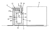
트럭(1)은, 트랜스미션 모듈(5)을 매개로 스위치 가능한 기어 세팅을 갖춘 자동 트랜스미션(9)의 입력 샤프트(7)에 연결되는 내연 기관(3)을 포함한다. 트랜스미션(9)의 출력 샤프트(11)는 차동 장치(13)를 매개로 트럭의 휠(15)에 연결된다. 트랜스미션 모듈(5)은, 서로 커플링될 수 있는 2개의 클러치 부분(17A 및 17B)을 갖춘 클러치(17)를 포함한다. 트랜스미션 모듈(5)은, 입력부(21) 및 출력부(23)를 갖춘 부분 모듈(19)을 더 포함한다. 부분 모듈(19)은 3개의 회전 부재(27, 29, 31)를 갖춘 바이패스 트랜스미션(25)을 포함하는데, 3개의 회전 부재 중 제3 회전 부재(31)는 브레이크(33)를 매개로 견고한 대상(35)에 커플링될 수 있다. 이러한 트랜스미션 모듈을 사용하면, 클러치 및 브레이크를 조작함으로써 토크 전달의 중단 없이 일대일의 기어비와 바이패스 트랜스미션의 기어비 사이의 스위치가 가능하다.The truck 1 comprises an internal combustion engine 3 which is connected to the input shaft 7 of the automatic transmission 9 with a switchable gear setting via the transmission module 5. The output shaft 11 of the transmission 9 is connected to the wheel 15 of the truck via the differential 13. The transmission module 5 comprises a clutch 17 with two clutch parts 17A and 17B that can be coupled to each other. The transmission module 5 further comprises a partial module 19 having an input 21 and an output 23. The partial module 19 comprises a bypass transmission 25 with three rotating members 27, 29, 31, of which the third rotating member 31 is rigid via the brake 33. It may be coupled to the subject 35. By using such a transmission module, it is possible to switch between the gear ratio of the one-to-one gear ratio and the gear ratio of the bypass transmission by manipulating the clutch and the brake.
Description
본 발명은 차량용, 더욱 구체적으로는 트럭용인 트랜스미션 모듈에 관한 것으로서, 상호 커플링될 수 있는 2개의 클러치 부분을 포함하는 클러치로서, 그 제1 클러치 부분은 차량의 구동원에 커플링될 수 있고, 그 제2 클러치 부분은 차량의 트랜스미션의 입력 샤프트에 커플링될 수 있는 것인 클러치를 포함하는 트랜스미션 모듈에 관한 것이다.The present invention relates to a transmission module for a vehicle, more specifically for a truck, comprising a clutch comprising two clutch portions that can be coupled to each other, the first clutch portion being coupled to a drive source of the vehicle, The second clutch portion relates to a transmission module comprising a clutch that can be coupled to an input shaft of a transmission of the vehicle.
이러한 유형의 트럭용 트랜스미션 모듈이 일반적으로 공지되어 있다. 이러한 트랜스미션 모듈은, 트럭에 적용될 때, 트럭의 트랜스미션과 구동원 사이에 위치하게 된다. 트랜스미션은, 클러치 수단 및 2개의 상호 협력하는 기어에 의해 형성되는 적어도 하나의 스위치 가능한 트랜스미션으로 이루어진다.Transmission modules for trucks of this type are generally known. Such a transmission module, when applied to a truck, is located between the transmission and the drive source of the truck. The transmission consists of at least one switchable transmission formed by clutch means and two mutually cooperating gears.
본 발명의 목적은 공지된 트랜스미션 모듈을 개량하는 것이다.It is an object of the present invention to improve on known transmission modules.
이러한 목적을 위해, 본 발명에 따른 트랜스미션 모듈은, 상기 트랜스미션 모듈이 입력부 및 출력부를 갖춘 부분 모듈을 더 포함하며, 이 부분 모듈은 트랜스미션뿐만 아니라 이 트랜스미션에 연결되는 추가적인 클러치 또는 브레이크를 포함하고, 상기 부분 모듈의 입력부는 제1 클러치 부분에 커플링되고/커플링되거나 차량의 구동원에 커플링될 수 있으며, 상기 부분 모듈의 출력부는 제2 클러치 부분에 커플링되고/커플링되거나 차량의 트랜스미션의 입력 샤프트에 커플링될 수 있으며, 상기 트랜스미션은 부분 모듈의 입력 샤프트 및 출력 샤프트의 회전 방향이 서로 동일하게 되도록 마련되는 것을 특징으로 한다.For this purpose, the transmission module according to the invention further comprises a partial module in which the transmission module has an input and an output, the partial module comprising an additional clutch or brake connected to the transmission as well as the transmission, and The input of the partial module can be coupled to the first clutch portion and / or to a drive source of the vehicle, and the output of the partial module is coupled to the second clutch portion and / or to the input of the transmission of the vehicle. It can be coupled to the shaft, the transmission is characterized in that the rotational direction of the input shaft and the output shaft of the partial module is provided to be the same.
본 발명에 따른 트랜스미션 모듈을 사용하면, 클러치 및 추가적인 클러치를 조작함으로써 토크 전달의 중단 없이 일대일의 기어비와 부분 모듈의 트랜스미션의 기어비 사이의 스위치가 가능하다. 그 결과로서, 트럭에서 사용될 때 본 발명에 따른 트랜스미션 모듈을 사용하면, 이러한 트랜스미션 모듈이 없는 경우의 기어비보다 2배 많은 기어비를 발생시킬 수 있다.With the transmission module according to the invention, it is possible to switch between a gear ratio of one-to-one and the gear ratio of the transmission of the partial module without interrupting torque transmission by manipulating the clutch and the additional clutch. As a result, the use of a transmission module according to the invention when used in a truck can result in a gear ratio twice as much as the gear ratio in the absence of such a transmission module.
공지된 트랜스미션에 대한 본 발명에 따른 트랜스미션의 장점은 다음과 같다.Advantages of the transmission according to the invention over known transmissions are as follows.
- 상기 트랜스미션 모듈은 최상단 기어로부터 최하단 기어까지 토크 전달과 함께 기어변속을 가능하게 한다. 이는 특히, 약간의 경사가 더 큰 파워를 요구하는 것으로 간주되기 때문에 최상단 기어(상단 기어)에서 사람이 저속 기어로 변속하고자 할 때 중요하다.The transmission module enables gear shifting with torque transfer from the top gear to the bottom gear. This is especially important when a person wants to shift to a lower gear from the top gear (upper gear) because some slope is considered to require greater power.
- 상기 트랜스미션 모듈은 또한 최하단 기어 하에서 여분의 기어가 발생되는 것을 가능하게 해준다. 이러한 여분의 저단 기어는, 보다 낮은 RPM으로 구동할 수 있도록 휠에 대한 최종 감속(end reduction)을 변경하는 것을 가능하게 해주며, 이는 연료 소모를 감소시킨다.The transmission module also makes it possible to generate extra gear under the bottom gear. This extra low gear makes it possible to change the final reduction of the wheel to drive at lower RPMs, which reduces fuel consumption.
- 브레이크의 능동 냉각 가능성의 결과로서 제1 기어(미끄럼 브레이크를 갖춤)에서의 크리피지(creepage) 동안 적절하고 긴 열 소산이 가능하다. 이는 더 낮은 크리피지 비율을 가능하게 해준다.Appropriate and long heat dissipation is possible during creepage in the first gear (with sliding brake) as a result of the possibility of active cooling of the brake. This allows for a lower creepage rate.
- 1-2 기어 변속, 3-4 기어 변속 및 5-6 기어 변속 사이에서 파워 변속이 가능하다.-Power shift between 1-2 gear shifts, 3-4 gear shifts and 5-6 gear shifts.
- 메인 클러치는 단지 파워 변속에 대해서만 사용되며, 차량의 발진을 위해서는 전혀 사용되지 않는다. 그 결과로서, 트랜스미션 모듈은 보다 경량의 구조를 가질 수 있고 마모는 상당히 줄어들게 된다. 차량의 완전한 수명을 위한 클러치 판을 구성하는 것이 가능하다. The main clutch is only used for power shifting, not for vehicle start-up. As a result, the transmission module can have a lighter structure and the wear is significantly reduced. It is possible to construct a clutch plate for the complete life of the vehicle.
클러치를 조작함으로써, 추가적인 클러치 또는 브레이크는 더욱 용이하게 개방 또는 폐쇄될 수 있도록 동기화 또는 언로딩될 수 있다.By operating the clutch, additional clutches or brakes can be synchronized or unloaded so that they can be opened or closed more easily.
부분 모듈을 비용 효과적으로 유지하기 위해, 추가적인 클러치 또는 브레이크는 클러치와 비교하여 임의의 현저한 파워를 소진할 수 없도록 구성된다. 추가적인 클러치는 바람직하게는, 클러치와 비교하여 임의의 현저한 파워를 소진할 수 없는 마찰 클러치 또는 마찰 브레이크로서 또는 물림 클러치(claw clutch) 또는 싱크로메시(synchromesh)로서 마련된다.In order to cost effectively maintain the partial module, the additional clutch or brake is configured to not consume any significant power compared to the clutch. The additional clutch is preferably provided as a friction clutch or friction brake which cannot consume any significant power as compared to the clutch or as a claw clutch or synchromesh.
트랜스미션은 바람직하게는, 기어 휠뿐만 아니라, 적어도 하나의 기어 휠을 그 기어 휠이 위치하는 샤프트에 커플링하기 위해, 물림 클러치 또는 싱크로메시와 같은 클러치 수단을 포함하는 적어도 하나의 스위치 가능한 트랜스미션으로 이루어진다.The transmission preferably consists of not only a gear wheel, but also at least one switchable transmission comprising clutch means such as a clutch clutch or a synchromesh for coupling the at least one gear wheel to the shaft on which the gear wheel is located. .
트랜스미션은 바람직하게는 푸쉬 벨트(push belt) 또는 체인 베리에이터(chain variator)와 같은 연속 가변 트랜스미션 요소를 포함한다.The transmission preferably comprises a continuously variable transmission element, such as a push belt or chain variator.
클러치는 바람직하게는, 조작되지 않으면 폐쇄되도록(통상 폐쇄되도록) 마련된다. 더욱이, 추가적인 클러치 또는 브레이크는, 조작되지 않으면 개방되도록(통상 개방되도록) 마련된다.The clutch is preferably provided to close (usually closed) if not operated. Moreover, additional clutches or brakes are provided to open (normally open) if not operated.
클러치는 바람직하게는 풀 액추에이터(pull actuator) 또는 푸시 액추에이터(push actuator)에 의해 조작되는데, 상기 풀 액추에이터는 클러치의 다이어프램 스프링에서 당겨서 클러치를 개방시키고 상기 푸시 액추에이터는 클러치의 다이어프램 스프링을 밀어서 클러치를 개방시킨다.The clutch is preferably operated by a pull actuator or push actuator, the pull actuator pulling on the diaphragm spring of the clutch to open the clutch and the push actuator pushing the diaphragm spring of the clutch to open the clutch. Let's do it.
클러치는 바람직하게는 건식 판 마찰 클러치로서 마련되고 추가적인 클러치 또는 브레이크가 건식 판 마찰 클러치로서 마련되거나, 또는 클러치는 습식 판 마찰 클러치로서 마련되고 추가적인 클러치 또는 브레이크가 습식 판 마찰 클러치로서 마련된다.The clutch is preferably provided as a dry plate friction clutch and an additional clutch or brake is provided as a dry plate friction clutch, or the clutch is provided as a wet plate friction clutch and an additional clutch or brake is provided as a wet plate friction clutch.
본 발명에 따른 트랜스미션 모듈의 실시예는, 상기 트랜스미션이 적어도 3개의 회전 부재를 갖춘 바이패스 트랜스미션에 의해 형성되며, 그 제1 회전 부재는 입력부에 연결되고 제2 회전 부재는 출력부에 연결되며 제3 회전 부재는 추가적인 클러치 또는 브레이크를 매개로 견고한 대상에 커플링될 수 있는 것을 특징으로 한다. 상기 견고한 대상은 예컨대 트랜스미션 하우징이다.In an embodiment of the transmission module according to the invention, the transmission is formed by a bypass transmission having at least three rotating members, the first rotating member connected to the input and the second rotating member connected to the output and The three rotating members can be coupled to a rigid object via an additional clutch or brake. The rigid object is for example a transmission housing.
제1 회전 부재는 바람직하게는 링 기어에 의해 형성되고 제2 회전 부재는 유성 기어가 베어링 장착되는 유성 기어 캐리어에 의해 형성되며 제3 회전 부재는 태양 기어에 의해 형성되거나, 또는 제1 회전 부재는 태양 기어에 의해 형성되고 제2 회전 부재는 제2 태양 기어에 의해 형성되며 제3 회전 부재는 유성 기어가 베어링 장착되는 캐리어에 의해 형성된다.The first rotating member is preferably formed by a ring gear and the second rotating member is formed by a planetary gear carrier bearing the planetary gear and the third rotating member is formed by the sun gear, or the first rotating member is It is formed by the sun gear and the second rotating member is formed by the second sun gear and the third rotating member is formed by the carrier on which the planetary gear is bearing-mounted.
바람직하게는 토션 댐퍼(torsion damper)는 제1 회전 부재와 제1 클러치 부분의 일부를 형성하는 클러치 커버 사이에 위치하게 된다. Preferably the torsion damper is positioned between the first rotating member and the clutch cover forming part of the first clutch portion.
더욱이, 바람직하게는 중간 하우징 부분이 클러치와 트랜스미션의 트랜스미션 하우징 사이에 위치하게 된다. Furthermore, preferably the intermediate housing part is located between the clutch and the transmission housing of the transmission.
바람직하게는, 제1 회전 부재와 중간 하우징 부분 사이에 회전 시일이 존재한다. 더욱이, 바람직하게는, 제1 회전 부재와 트랜스미션의 제1 샤프트 사이에 회전 시일이 존재한다.Preferably, there is a rotating seal between the first rotating member and the intermediate housing portion. Furthermore, preferably there is a rotating seal between the first rotating member and the first shaft of the transmission.
제1 회전 부재와 클러치 커버 사이의 연결부는 바람직하게는 연결 슬리브를 통해 클러치 액추에이터 아래로 통과한다.The connection between the first rotating member and the clutch cover preferably passes under the clutch actuator through the connecting sleeve.
더욱이, 바람직하게는 제1 회전 부재 및 제3 회전 부재는 트랜스미션의 제1 샤프트 상에 직접 베어링 장착된다.Furthermore, preferably the first and third rotating members are bearing mounted directly on the first shaft of the transmission.
트랜스미션이 바이패스 트랜스미션에 의해 형성되는 것인 앞서 설명한 실시예에 대한 대안을 형성하며 본 발명에 따르는 트랜스미션 모듈의 다른 실시예는, 상기 트랜스미션 모듈이, 각각 입력 샤프트 및 출력 샤프트를 갖춘 2개의 부분 트랜스미션을 포함하며 제1의 부분 트랜스미션의 입력 샤프트는 상기 입력부에 연결되고 제2의 부분 트랜스미션의 출력 샤프트는 상기 출력부에 연결되며 제1의 부분 트랜스미션의 출력 샤프트 및 제2의 부분 트랜스미션의 입력 샤프트는 추가적인 클러치에 의해 서로 커플링될 수 있는 것을 특징으로 한다. 상기 부분 트랜스미션은, 예컨대 기어 트레인, 체인 트랜스미션 또는 벨트 트랜스미션일 수 있다.Another embodiment of the transmission module according to the present invention forms an alternative to the previously described embodiment wherein the transmission is formed by a bypass transmission, wherein the transmission module comprises two partial transmissions each having an input shaft and an output shaft. Wherein the input shaft of the first partial transmission is connected to the input and the output shaft of the second partial transmission is connected to the output and the output shaft of the first partial transmission and the input shaft of the second partial transmission are It can be coupled to each other by an additional clutch. The partial transmission can be, for example, a gear train, chain transmission or belt transmission.
본 발명에 따른 트랜스미션 모듈의 추가적인 실시예는, 제1의 부분 트랜스미션이 출력부의 방향으로 가속시키고 제2의 부분 트랜스미션은 출력부의 방향으로 감속시키는 것을 특징으로 한다. 그 결과로서, 조작 중에 추가적인 클러치에 의해 전달되는 토크는 감소되며, 이에 따라 추가적인 클러치는 더 적은 크기의 부하를 받는다.A further embodiment of the transmission module according to the invention is characterized in that the first partial transmission accelerates in the direction of the output and the second partial transmission decelerates in the direction of the output. As a result, the torque transmitted by the additional clutch during operation is reduced, so that the additional clutch is loaded with less magnitude.
본 발명에 따른 트랜스미션 모듈의 또 다른 실시예는, 입력부의 조작 중의 RPM을 출력부의 RPM으로 나눈 것으로 정의되는 부분 모듈의 기어비가 1보다 큰 것을 특징으로 한다. 바람직하게는 부분 모듈의 기어비는 1.3 이상이다. Another embodiment of the transmission module according to the invention is characterized in that the gear ratio of the partial module, defined as the RPM of the input unit divided by the RPM of the output unit, is greater than one. Preferably the gear ratio of the partial module is at least 1.3.
부분 모듈은, 트럭의 기존의 구동 트레인에 붙박이로 되어있을 수 있는 개별 모듈로서 마련될 수 있다. 이러한 목적을 위해, 부분 모듈의 입력부 및 출력부에는 바람직하게는 각각 제2 클러치 부분 및/또는 트럭의 트랜스미션의 입력 샤프트 또는 구동원 및/또는 제1 클러치 부분에 커플링하기 위한 치형부가 마련된다. 상기 치형부는 예컨대 스플라인(spline)일 수 있다. 출력부는 이때 바람직하게는 제2 클러치 부분에 연결되는 연장 샤프트에 의해 형성된다. 이러한 연장 샤프트는, 트랜스미션 모듈이 트럭에서 사용될 때 트럭의 트랜스미션의 입력 샤프트를 연장하기 위해 사용되며, 이에 따라 이러한 입력 샤프트는 제2 클러치 부분에 연결될 수 있다.The partial module may be provided as a separate module which may be built in to the truck's existing drive train. For this purpose, the input and output portions of the partial module are preferably provided with teeth for coupling to the input shaft or drive source and / or the first clutch portion of the transmission of the second clutch portion and / or the truck, respectively. The teeth can be, for example, splines. The output part is then formed by an extension shaft, which is preferably connected to the second clutch part. This extension shaft is used to extend the input shaft of the truck's transmission when the transmission module is used in the truck, such that the input shaft can be connected to the second clutch portion.
바람직하게는, 클러치를 조작하기 위한 조작 수단 및/또는 추가적인 클러치를 조작하기 위한 추가적인 조작 수단은 부분 모듈의 일부를 형성한다. 상기 조작 수단 및 추가적인 조작 수단에는 바람직하게는 압축 공기가 공급된다. 조작 수단 및 추가적인 조작 수단에 대한 이러한 공기 공급은 바람직하게는 중간 하우징 부분을 통해 안내된다.Preferably, the operating means for operating the clutch and / or the additional operating means for operating the additional clutch form part of the partial module. The operating means and the further operating means are preferably supplied with compressed air. This air supply to the operating means and further operating means is preferably guided through the intermediate housing part.
본 발명은 또한, 본 발명에 따른 트랜스미션 모듈에 적용될 수 있는 부분 모듈에 관한 것이다.The invention also relates to a partial module which can be applied to a transmission module according to the invention.
클러치를 조작(작동)함으로써, 추가적인 클러치 또는 브레이크는 간단한 방식으로 개방 또는 폐쇄될 수 있도록 동기화 또는 언로딩될 수 있다.By operating (actuating) the clutch, additional clutches or brakes can be synchronized or unloaded so that they can be opened or closed in a simple manner.
클러치 및 추가적인 클러치 또는 브레이크를 조작(작동)함으로써, 트랜스미션의 입력 샤프트와 구동 샤프트 사이에서 1:1과 트랜스미션 사이로 토크 중단 없이 기어를 스위치하는 것이 가능하다.By operating (actuating) the clutch and an additional clutch or brake, it is possible to switch gears without torque interruption between 1: 1 and the transmission between the input shaft and the drive shaft of the transmission.
추가적인 클러치 또는 브레이크를 조작(작동)함으로써, 차량은 정방향 또는 역방향으로 시동될 수 있다. By operating (actuating) the additional clutch or brake, the vehicle can be started in the forward or reverse direction.
추가적인 클러치 또는 브레이크를 조작(작동)함으로써, 차량은 정방향 또는 역방향으로 발진될 수 있고, 다음으로 클러치를 조작(작동)함으로써 차량의 휠의 토크 중단 없이 더 높은 기어로의 변속이 가능하다. By operating (actuating) the additional clutch or brake, the vehicle can be started in the forward or reverse direction, and then by operating (actuating) the clutch, it is possible to shift to a higher gear without interrupting the torque of the wheel of the vehicle.
본 발명에 따르면 공지된 트랜스미션 모듈보다 개량된 트랜스미션 모듈을 얻을 수 있다.According to the present invention, a transmission module improved from a known transmission module can be obtained.
본 발명은 도면에 제시된 본 발명에 따른 트랜스미션 모듈의 실시예에 기초하여 이하에서 더욱 상세하게 설명될 것이다.
도 1은 트럭에서 사용되는, 본 발명에 따른 트랜스미션 모듈의 제1 실시예의 개략도를 제공한다.
도 2는 트럭에서 사용되는, 본 발명에 따른 트랜스미션 모듈의 제2 실시예의 개략도를 제공한다.
도 3은 습식 판 클러치가 마련되는, 도 1에 제시된 트랜스미션 모듈의 구성 실시예에 대한 개략도를 제공한다.
도 4는 건식 판 클러치가 마련되는, 도 1에 제시된 트랜스미션 모듈의 개략도를 제공한다.
도 5는 습식 판 클러치가 마련되는, 도 2에 제시된 트랜스미션 모듈의 구성 실시예에 대한 개략도를 제공한다.
도 6은 건식 판 클러치가 마련되는, 도 2에 제시된 트랜스미션 모듈의 구성 실시예에 대한 개략도를 제공한다.
도 7 내지 도 23은 추가 실시예를 나타낸다. The invention will be explained in more detail below on the basis of an embodiment of a transmission module according to the invention presented in the drawings.
1 provides a schematic diagram of a first embodiment of a transmission module according to the invention for use in a truck.
2 provides a schematic diagram of a second embodiment of a transmission module according to the invention for use in a truck.
3 provides a schematic diagram of a configuration embodiment of the transmission module shown in FIG. 1, in which a wet plate clutch is provided.
4 provides a schematic diagram of the transmission module shown in FIG. 1, provided with a dry plate clutch.
FIG. 5 provides a schematic diagram of a configuration embodiment of the transmission module shown in FIG. 2 in which a wet plate clutch is provided.
FIG. 6 provides a schematic diagram of a configuration embodiment of the transmission module shown in FIG. 2 in which a dry plate clutch is provided.
7-23 show further embodiments.
도 1은 트럭에서 사용되는, 본 발명에 따른 트랜스미션 모듈의 제1 실시예의 개략도를 제시한 것이다. 트럭(1)은, 트랜스미션 모듈(5)을 매개로 예컨대 스위치 가능한 구동부를 갖춘 자동 트랜스미션(9)의 입력 샤프트(7)에 연결되는 내연 기관(3)을 구비한다. 트랜스미션(9)의 출력 샤프트(11)는 차동 장치(13)에 의해 트럭의 휠(15)에 연결된다.1 shows a schematic diagram of a first embodiment of a transmission module according to the invention for use in a truck. The
트랜스미션 모듈(5)은, 서로 커플링될 수 있는 2개의 클러치 부분(17A 및 17B)을 갖춘 클러치(17)를 포함한다. 트랜스미션 모듈(5)은, 입력부(21) 및 출력부(23)를 갖춘 부분 모듈(19)을 더 포함한다. 입력부(21)는 클러치 부분(17A)에 커플링되고 출력부(23)는 클러치 부분(17B)에 커플링된다.The
부분 모듈(19)은, 3개의 회전 부재를 갖춘 바이패스 트랜스미션(25)을 구비하는데, 제1 회전 부재(27)는 입력부(21)에 연결되며, 제2 회전 부재(29)는 출력부(23)에 연결되고, 제3 회전 부재(31)는 브레이크(33)를 매개로 예컨대 트랜스미션의 하우징에 의해 형성되는 견고한 대상(35)에 커플링될 수 있다. 바이패스 트랜스미션(25)은, 제1 회전 부재(27) 및 제2 회전 부재(29)의 회전 방향이 서로 동일하게 되도록 제작된다. 브레이크(33)는 클러치(17)와 비교하여 현저한 파워를 소진할 수 없다.The
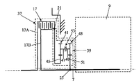
도 2는 트럭에서 사용되는, 본 발명에 따른 트랜스미션 모듈의 제2 실시예의 개략도를 제공한다. 제1 실시예의 부분과 동일한 모든 부분에는 동일한 도면 부호가 지시되어 있다.2 provides a schematic diagram of a second embodiment of a transmission module according to the invention for use in a truck. All the same parts as those of the first embodiment are designated with the same reference numerals.
이러한 트랜스미션 모듈(37)의 부분 모듈(39)은, 각각 입력 샤프트(45, 49) 및 출력 샤프트(47, 51)를 구비하는 2개의 부분 트랜스미션(41 및 43)을 갖추고 있다. 부분 트랜스미션은 기어 쌍에 의해 형성된다. 입력 샤프트(45)는 입력부(21)에 연결되고 출력 샤프트(51)는 출력부(23)에 연결된다. 출력 샤프트(47) 및 입력 샤프트(49)는 추가적인 클러치(53)에 의해 서로 커플링될 수 있다. 추가적인 클러치(53)는 클러치(17)와 비교하여 현저한 파워를 소진할 수 없으며, 클러치와 비교하여 현저한 파워를 소진할 수 없는 마찰 클러치 또는 마찰 브레이크로서 또는 물림 클러치 또는 싱크로메시로서 마련된다. 출력부(23)의 방향으로 부분 트랜스미션(41)은 가속 효과를 가지며, 부분 트랜스미션(43)은 감속 효과를 갖는다.The
입력부(21)의 조작 중의 RPM을 출력부(23)의 RPM으로 나눈 것으로 정의되는, 트랜스미션 모듈(5 및 37)의 기어비는 대략 1.3이다.The gear ratios of the
도 3은 도 1에 제시된 트랜스미션 모듈의 구성 실시예에 대한 개략도를 제시한 것이다. 이 실시예에서 마련되는 클러치(17)는 습식 판 클러치이다.FIG. 3 shows a schematic diagram of a configuration embodiment of the transmission module shown in FIG. 1. The clutch 17 provided in this embodiment is a wet plate clutch.
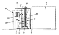
도 4는 도 1에 제시된 트랜스미션 모듈의 다른 구성 실시예에 대한 개략도를 제시한 것이다. 여기서 클러치(17)는 건식 판 클러치로서 마련된다. 입력부는, 스플라인 치형부(57) 또는 다른 기계적 연결부를 매개로 클러치 커버에 의해 형성되는 클러치 부분(17A)에 커플링되는 연결판(55)으로 구성된다. 출력부는, 또한 스플라인 연결부(61) 또는 다른 기계적 연결부를 매개로 클러치 판에 의해 형성되는 제2 클러치 부분(17B)에 연결되는 연장 샤프트(59)로 형성되며, 스플라인 연결부(63)를 매개로 트랜스미션(9)의 입력 샤프트(7)에 연결된다.FIG. 4 shows a schematic diagram of another configuration embodiment of the transmission module shown in FIG. 1. The clutch 17 is provided here as a dry plate clutch. The input consists of a connecting
부분 모듈(19)은 클러치(17)를 조작하기 위한 조작 수단을 포함한다. 이러한 조작 수단은 액추에이터(65)에 의해 형성된다. 브레이크를 조작하기 위한 추가적인 조작 수단(도시되어 있지 않음)도 또한 부분 모듈(19)의 일부를 형성한다.The
도 5는 도 2에 제시된 트랜스미션 모듈의 구성 실시예에 대한 개략도를 제시한 것이다. 클러치(17)는 습식 판 클러치로서 또한 마련된다.FIG. 5 shows a schematic diagram of a configuration embodiment of the transmission module shown in FIG. 2. The clutch 17 is also provided as a wet plate clutch.
도 6은 도 2에 제시된 트랜스미션 모듈의 다른 구성 실시예에 대한 개략도를 제시한 것이다. 도 4에 제시된 제1 실시예의 부분과 동일한 모든 부분에는 동일한 도면 부호가 지시되어 있다. 클러치(17)는 여기서 건식 판 클러치로서 마련된다. 부분 모듈의 일부를 형성하는 추가적인 조작 수단(하지만, 이번에는 추가적인 클러치를 위한 것임)은 여기에서 제시되지 않는다.6 shows a schematic diagram of another configuration embodiment of the transmission module shown in FIG. 2. All the same parts as those of the first embodiment shown in FIG. 4 are designated with the same reference numerals. The clutch 17 is here provided as a dry plate clutch. No further means of operation forming part of the partial module, but this time for the additional clutch, are not presented here.
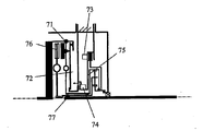
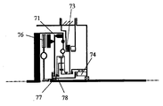
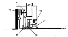
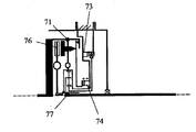
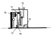
도 7 내지 도 10은 건식 판 클러치 및 건식 판 브레이크를 갖춘 실시예를 제시한다. 도 7에 제시된 실시예는 시일(펠릿)의 특정 구성 및 바이패스 트랜스미션에 대한 특정 연결을 포함한다. 도면부호 71은, 토션 스프링 및 클러치 커버에 대한 연결판(72)의 연결부를 지시하기 위해 사용된 것이다. 브레이크 액추에이터 및 클러치 액추에이터는 각각 73 및 74로 지시되고, 바이패스 트랜스미션은 75로 지시되며 클러치 판은 76으로 지시된다. 입력 샤프트는 스플라인 연결부(77)를 매개로 클러치 판에 연결된다. 도 8에 있어서, 바이패스 트랜스미션은 클러치 하우징 내측에 위치하게 된다. 7-10 show an embodiment with a dry plate clutch and a dry plate brake. The embodiment shown in FIG. 7 includes a specific configuration of the seal (pellets) and a specific connection to the bypass transmission.
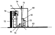
도 9 내지 도 10은, 클러치 액추에이터가 트랜스미션 하우징으로부터 직접 작동될 수 있도록 옮겨진 실시예를 제시한 것이다. 이는 2개의 축방향 베어링 및 관통 커플링을 필요로 한다. 관통 커플링은, 제1 샤프트와 바이패스 트랜스미션 사이에서 연결판을 통해 돌출되는 치형 연결부/스플라인 연결부/키 형성된 연결부로서 마련된다. 관통 커플링(78)은 연결판과 동일한 속도로 회전하지만, 이러한 연결판에 대해 축방향으로 사실상 슬라이딩 가능하다.9 to 10 show an embodiment in which the clutch actuator is moved so that it can be operated directly from the transmission housing. This requires two axial bearings and through couplings. The through coupling is provided as a toothed connection / spline connection / keyed connection which projects through the connecting plate between the first shaft and the bypass transmission. The through
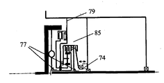
도 11 내지 도 18은, 건식 판 클러치 및 습식 판 브레이크(82)를 갖춘 실시예를 제시한다. 도 12는 도 11에 개략적으로 제시된 실시예의 구체적인 구성이며, 도 14는 도 13에 개략적으로 제시된 실시예의 구체적인 구성이다. 여기서 중간 부재는 79로서 지시되어 있고 트랜스미션 하우징은 80으로서 지시되어 있다. 제1 클러치 부분의 레버와 클러치 액추에이터(74) 사이에는 스러스트 베어링(81)이 위치하게 된다. 트랜스미션의 제1 샤프트(83)는 이때 연장되지만, 일 부품으로 제작된다(별도의 샤프트 연장부는 없음). 도 15는 추가적인 변형을 제시한 것이다.11-18 show an embodiment with a dry plate clutch and a
도 16 및 도 17에 제시된 실시예에 있어서, 클러치 액추에이터(74)는 트랜스미션 하우징으로부터 직접 작동될 수 있도록 옮겨져 있다. 이는 2개의 축방향 베어링 및 관통 커플링을 필요로 한다. 관통 커플링(78)은, 제1 샤프트와 바이패스 트랜스미션 사이에서 연결판을 통해 돌출되는 치형 연결부/스플라인 연결부/키 형성된 연결부로서 마련된다. 관통 커플링은 연결판과 동일한 속도로 회전하지만, 이러한 연결판에 대해 축방향으로 사실상 슬라이딩 가능하다. 도 18은 또한 도 17의 개략도의 구체적인 실시예이다.In the embodiment shown in FIGS. 16 and 17, the
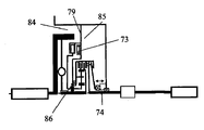
도 19 내지 도 20은, 습식 판 클러치 및 건식 판 브레이크를 갖춘 실시예를 제시한다. 84는 건식 공간을 지시하며 85는 습식 공간을 지시한다. 작동 힘은 베어링(86)을 통해 지지된다. 도 19에 제시된 실시예는, 발진 요소(브레이크)가 건식이며 파워 변속 요소(클러치)가 습식이라는 장점을 갖는다. 브레이크 액추에이터 및 클러치의 지지 힘은 중간 하우징 부분에서 직접 지지될 수 있으며, 이는 유리하다. 도 20에 제시된 실시예에 있어서, 제1 샤프트는 연장된다.19-20 show an embodiment with a wet plate clutch and a dry plate brake. 84 indicates dry space and 85 indicates wet space. The operating force is supported through the
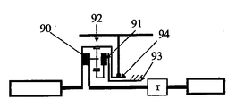
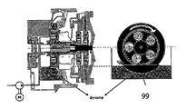
도 21, 도 22 및 도 23에서는, 습식 판 클러치 및 습식 판 브레이크를 갖춘 실시예가 제시되어 있다. 파워 변속 모듈은 여기서 토크 변환기에 대한 대체재로서 구성된다. 트랜스미션의 기어비 범위는 이때 스위치 가능한 예감속(prereduction)에 의해 작아질 수 있으며, 이는 높은 효율을 제공한다(이는 토크 변환기가 갖지 못한 점임). 커플링[로크 업(lock-up)]은 90으로 지시되어 있고 브레이크는 91로 지시되어 있다. 유성 기어 세트는 도면부호가 92이며 하우징은 도면부호가 93이다. 오일 펌프에 대한 연결부는 94로서 지시되어 있다. 도 22에 있어서 트랜스미션 섬프는 95로서 지시되어 있으며, 96은 바로 오일을 사용하기 위한 연결부를 지시한 것이다. 섬프 모듈은 97로 지시되어 있으며 98은 유성 기어 세트의 냉각 및 윤활을 위한 전기 오일 펌프이다. 트랜스미션의 오일 섬프는 파워 변속 모듈의 오일 섬프에 연결된다. 파워 변속 모듈 오일 섬프에 있어서, 습식 브레이크 또는 클러치가 오일 속에서 연속적으로 회전할 필요가 없도록 파티션/리셉터클이 설치되며, 이는 마찰 손실을 감소시킨다. 도 23에 있어서 브레이크가 미끄럼 손실을 적게 갖도록 브레이크로부터 오일을 멀리 유지하기 위한 파티션은 99로서 지시되어 있다.21, 22 and 23, an embodiment with a wet plate clutch and a wet plate brake is shown. The power transmission module is here configured as a substitute for the torque converter. The gear ratio range of the transmission can then be reduced by means of switchable prereduction, which provides high efficiency (which is what the torque converter does not have). The coupling (lock-up) is indicated at 90 and the brake is indicated at 91. The planetary gear set is 92 and the housing is 93. The connection to the oil pump is indicated as 94. In FIG. 22 the transmission sump is indicated as 95 and 96 is the connection for oil use. The sump module is indicated as 97 and 98 is an electric oil pump for cooling and lubrication of the planetary gear set. The oil sump of the transmission is connected to the oil sump of the power shift module. In the power transmission module oil sump, a partition / receptacle is installed so that the wet brake or clutch does not need to rotate continuously in oil, which reduces frictional losses. In FIG. 23 the partition for keeping oil away from the brake is indicated as 99 so that the brake has less slip loss.
본 발명은 도면에 기초하여 앞서 설명되었지만, 본 발명은 도면에 도시된 실시예로 한정되는 임의의 방식 또는 수단이 아니라는 것을 이해해야 한다. 본 발명은 또한 청구범위에 의해 한정되는 사상 또는 범위 내에서 도면에 도시된 실시예로부터 벗어나는 실시예로 확장된다.Although the invention has been described above based on the drawings, it should be understood that the invention is not in any way or means limited to the embodiments shown in the drawings. The invention also extends to embodiments that deviate from the embodiments shown in the drawings within the spirit or scope defined by the claims.
1 : 트럭
3 : 내연 기관
5 : 트랜스미션 모듈
7 : 입력 샤프트
9 : 트랜스미션
11 : 출력 샤프트
13 : 차동 장치
15 : 휠
17 : 클러치
19 : 부분 모듈
21 : 입력부
23 : 출력부
27, 29, 31 : 회전 부재1: truck
3: internal combustion engine
5: transmission module
7: input shaft
9: Transmission
11: output shaft
13: differential device
15: wheel
17: clutch
19: partial module
21: input unit
23: output unit
27, 29, 31: rotating member
Claims (32)
A partial module which can be used in the transmission module according to any one of claims 1 to 31.
Applications Claiming Priority (8)
| Application Number | Priority Date | Filing Date | Title |
|---|---|---|---|
| NL2003064 | 2009-06-22 | ||
| NL2003064 | 2009-06-22 | ||
| NL2004096 | 2010-01-14 | ||
| NL2004096 | 2010-01-14 | ||
| NL2004151 | 2010-01-26 | ||
| NL2004151 | 2010-01-26 | ||
| NL2004387A NL2004387B1 (en) | 2009-06-22 | 2010-03-12 | Transmission module for a truck |
| NL2004387 | 2010-03-12 |
Publications (1)
| Publication Number | Publication Date |
|---|---|
| KR20120030555A true KR20120030555A (en) | 2012-03-28 |
Family
ID=45876516
Family Applications (1)
| Application Number | Title | Priority Date | Filing Date |
|---|---|---|---|
| KR1020127001349A KR20120030555A (en) | 2009-06-22 | 2010-06-22 | Transmission module for a lorry |
Country Status (6)
| Country | Link |
|---|---|
| US (1) | US8882625B2 (en) |
| EP (1) | EP2446171B1 (en) |
| JP (1) | JP5658246B2 (en) |
| KR (1) | KR20120030555A (en) |
| CN (1) | CN102648363B (en) |
| WO (1) | WO2010151113A1 (en) |
Families Citing this family (3)
| Publication number | Priority date | Publication date | Assignee | Title |
|---|---|---|---|---|
| WO2013077736A1 (en) * | 2011-11-23 | 2013-05-30 | Dti Group B.V. | Flywheel module for a vehicle, as well as methods of operating the flywheel module |
| SE540703C2 (en) * | 2017-02-08 | 2018-10-16 | Scania Cv Ab | A gearbox for vehicles |
| NL2018971B1 (en) * | 2017-05-24 | 2018-12-07 | Punch Powertrain Nv | a shifting method for a transmission, a transmission system, a computer program product, and a vehicle. |
Family Cites Families (12)
| Publication number | Priority date | Publication date | Assignee | Title |
|---|---|---|---|---|
| IT212323Z2 (en) | 1987-10-26 | 1989-07-04 | Same Spa | GEARBOX FOR TRACTORS |
| JP2002048213A (en) * | 2000-08-01 | 2002-02-15 | Toyota Motor Corp | Speed change gear equipped with variable speed change mechanism |
| JP3870716B2 (en) * | 2001-05-14 | 2007-01-24 | 日産自動車株式会社 | Transmission torsional damper mechanism |
| EP1258658A3 (en) * | 2001-05-14 | 2009-07-15 | Nissan Motor Company, Limited | Auxiliary Transmission |
| JP2004125055A (en) * | 2002-10-02 | 2004-04-22 | Jatco Ltd | Hydraulic control device for transmission for vehicle |
| CN101189449B (en) * | 2005-04-08 | 2012-07-25 | Dti集团有限公司 | Drive for a vehicle, in particular a lorry |
| WO2007011212A1 (en) * | 2005-07-18 | 2007-01-25 | Dti Group B.V. | Clutch usable in a vehicle drive, as well as a drive provided with the clutch |
| US8235857B2 (en) * | 2005-07-18 | 2012-08-07 | Dti Group B.V. | Gear module |
| WO2007043875A1 (en) | 2005-10-14 | 2007-04-19 | Dti Group B.V. | Vehicle with two parallel drivelines |
| CN101303073B (en) * | 2008-06-27 | 2010-08-11 | 华南理工大学 | Division and convergent current type multiple-shift automatic transmission system |
| US9156345B2 (en) * | 2009-03-06 | 2015-10-13 | Dti Group, Bv | Transmission for an electric or hybrid drive |
| JP2011002034A (en) * | 2009-06-18 | 2011-01-06 | Toyota Motor Corp | Forward movement and backward movement change-over device for vehicle |
-
2010
- 2010-06-22 KR KR1020127001349A patent/KR20120030555A/en not_active Application Discontinuation
- 2010-06-22 EP EP10745445.6A patent/EP2446171B1/en active Active
- 2010-06-22 JP JP2012517424A patent/JP5658246B2/en not_active Expired - Fee Related
- 2010-06-22 CN CN201080037519.7A patent/CN102648363B/en not_active Expired - Fee Related
- 2010-06-22 US US13/380,488 patent/US8882625B2/en not_active Expired - Fee Related
- 2010-06-22 WO PCT/NL2010/000101 patent/WO2010151113A1/en active Application Filing
Also Published As
| Publication number | Publication date |
|---|---|
| EP2446171A1 (en) | 2012-05-02 |
| US8882625B2 (en) | 2014-11-11 |
| CN102648363A (en) | 2012-08-22 |
| EP2446171B1 (en) | 2019-08-14 |
| JP2012530890A (en) | 2012-12-06 |
| CN102648363B (en) | 2016-01-20 |
| WO2010151113A1 (en) | 2010-12-29 |
| US20120142482A1 (en) | 2012-06-07 |
| JP5658246B2 (en) | 2015-01-21 |
Similar Documents
| Publication | Publication Date | Title |
|---|---|---|
| EP2853779B1 (en) | Vehicle power transmission device | |
| US20080245168A1 (en) | Automatic Transmission and Shift Control Method For Said Transmission | |
| EP2360044A1 (en) | Transmission for hybrid vehicle | |
| US8806975B2 (en) | Method for running a drive line | |
| JP2011099555A (en) | Two-speed transmission for electric vehicle | |
| JP2009510341A (en) | Automatic transmission for motor vehicle and its shift change method | |
| CN101761612A (en) | Steam-driven vertical double clutch type gearbox | |
| US7156768B2 (en) | Multi-stage transmission | |
| US8584543B2 (en) | Drive train of a motor vehicle | |
| US8870704B2 (en) | Multistage transmission | |
| KR101836513B1 (en) | Automated manual transmission for vehicle | |
| CN111033084B (en) | Automatic transmission for a motor vehicle and method for shifting an automatic transmission | |
| KR100836107B1 (en) | A 8th-speed power train of an automatic transmission for car | |
| KR20120030555A (en) | Transmission module for a lorry | |
| US20200086848A1 (en) | Drive train and motor vehicle | |
| US7175562B2 (en) | Multi-stage transmission | |
| US10710444B2 (en) | Hybrid drive for a hybrid vehicle | |
| KR100836106B1 (en) | A 8th-speed power train of an automatic transmission for car | |
| CN109922980B (en) | Transmission assembly and drive device for hybrid vehicle | |
| RU2498129C2 (en) | Method of braking under high rotary speeds by automatic gearbox with hydrodynamic torque converter | |
| US20120316022A1 (en) | Transmission system for a vehicle | |
| JP2004522910A (en) | Car drive unit | |
| JP4035423B2 (en) | transmission | |
| JP2005299881A (en) | Transmission for vehicle | |
| JP2010007781A (en) | Hydraulic control device |
Legal Events
| Date | Code | Title | Description |
|---|---|---|---|
| A201 | Request for examination | ||
| AMND | Amendment | ||
| E902 | Notification of reason for refusal | ||
| AMND | Amendment | ||
| E902 | Notification of reason for refusal | ||
| AMND | Amendment | ||
| E601 | Decision to refuse application | ||
| AMND | Amendment | ||
| E902 | Notification of reason for refusal |