US8882087B2 - Pneumatic spring device for a rail vehicle - Google Patents
Pneumatic spring device for a rail vehicle Download PDFInfo
- Publication number
- US8882087B2 US8882087B2 US13/562,027 US201213562027A US8882087B2 US 8882087 B2 US8882087 B2 US 8882087B2 US 201213562027 A US201213562027 A US 201213562027A US 8882087 B2 US8882087 B2 US 8882087B2
- Authority
- US
- United States
- Prior art keywords
- rings
- core
- pneumatic spring
- bead
- spring device
- Prior art date
- Legal status (The legal status is an assumption and is not a legal conclusion. Google has not performed a legal analysis and makes no representation as to the accuracy of the status listed.)
- Active, expires
Links
Images


Classifications
-
- F—MECHANICAL ENGINEERING; LIGHTING; HEATING; WEAPONS; BLASTING
- F16—ENGINEERING ELEMENTS AND UNITS; GENERAL MEASURES FOR PRODUCING AND MAINTAINING EFFECTIVE FUNCTIONING OF MACHINES OR INSTALLATIONS; THERMAL INSULATION IN GENERAL
- F16F—SPRINGS; SHOCK-ABSORBERS; MEANS FOR DAMPING VIBRATION
- F16F9/00—Springs, vibration-dampers, shock-absorbers, or similarly-constructed movement-dampers using a fluid or the equivalent as damping medium
- F16F9/02—Springs, vibration-dampers, shock-absorbers, or similarly-constructed movement-dampers using a fluid or the equivalent as damping medium using gas only or vacuum
- F16F9/04—Springs, vibration-dampers, shock-absorbers, or similarly-constructed movement-dampers using a fluid or the equivalent as damping medium using gas only or vacuum in a chamber with a flexible wall
- F16F9/0409—Springs, vibration-dampers, shock-absorbers, or similarly-constructed movement-dampers using a fluid or the equivalent as damping medium using gas only or vacuum in a chamber with a flexible wall characterised by the wall structure
-
- F—MECHANICAL ENGINEERING; LIGHTING; HEATING; WEAPONS; BLASTING
- F16—ENGINEERING ELEMENTS AND UNITS; GENERAL MEASURES FOR PRODUCING AND MAINTAINING EFFECTIVE FUNCTIONING OF MACHINES OR INSTALLATIONS; THERMAL INSULATION IN GENERAL
- F16F—SPRINGS; SHOCK-ABSORBERS; MEANS FOR DAMPING VIBRATION
- F16F9/00—Springs, vibration-dampers, shock-absorbers, or similarly-constructed movement-dampers using a fluid or the equivalent as damping medium
- F16F9/02—Springs, vibration-dampers, shock-absorbers, or similarly-constructed movement-dampers using a fluid or the equivalent as damping medium using gas only or vacuum
- F16F9/04—Springs, vibration-dampers, shock-absorbers, or similarly-constructed movement-dampers using a fluid or the equivalent as damping medium using gas only or vacuum in a chamber with a flexible wall
- F16F9/0454—Springs, vibration-dampers, shock-absorbers, or similarly-constructed movement-dampers using a fluid or the equivalent as damping medium using gas only or vacuum in a chamber with a flexible wall characterised by the assembling method or by the mounting arrangement, e.g. mounting of the membrane
Definitions
- the invention relates to a pneumatic spring device for a rail vehicle, comprising a pneumatic spring bellows which is arranged between a sprung chassis (a rail vehicle) and an unsprung subframe (bogie) and is provided with reinforcement, which are embedded in the bellows material, as reinforcing elements, wherein individual layers or a plurality of layers of reinforcements or fabric layers made of reinforcements can be provided.
- the pneumatic spring bellows has a bead ring for fastening or clamping the pneumatic spring bellows to correspondingly designed stop rings (flanges) of the chassis and unsprung subframe, wherein the bead ring is provided with a core, and the reinforcements loop or engage around the core, that is, are customarily guided around the cores at a certain distance.
- a multiplicity of pneumatic spring systems/a pneumatic spring device comprising pneumatic spring bellows which have particular embodiments of the bead rings and looping around by means of the reinforcements are known in the prior art.
- the reinforcing fabric that is, the reinforcements
- the reinforcing fabric are arranged close to the surface of the pneumatic springs and therefore, at the ends of the pneumatic springs, are also arranged in the region of the clamping point and in the vicinity of the flanges.
- the surface material of the pneumatic spring which is generally composed of rubber, is subjected to severe frictional wear due to relative movements, the reinforcements may also be damaged.
- One countermeasure is to apply additional rubber layers, but this makes production expensive and also does not provide a fundamental remedy.
- DE 40 11 517 A1 discloses a pneumatic spring bellows for rail vehicles, the pneumatic spring bellows having embedded reinforcing layers or reinforcements and being provided with annular beads which are each reinforced by an inner core ring.
- the pneumatic spring bellows is vulcanized onto the stop ring in the clamping or bearing region formed between the bead ring, referred to here as the “annular bead”, and stop ring. This prevents movements between the bellows surface and the generally metallic stop ring and, in consequence, avoids abrasion of the bellows material.
- a disadvantage in this case is the relatively costly production of vulcanized connections of this type.
- DE 21 08 694 C2 discloses an optimization of the connection of the reinforcements and core by a particular shaping, rounded in an elongated manner, of the core and a correspondingly formed looping around by means of the reinforcements.
- DE 21 08 694 C2 discloses an optimization of the connection of the reinforcements and core by a particular shaping, rounded in an elongated manner, of the core and a correspondingly formed looping around by means of the reinforcements.
- the abovementioned abrasion problem is still not solved by the above.
- the bead ring has a core made of two core rings positioned separately in the bead ring, wherein the reinforcement elements are guided in an S-configuration between the core rings and loop around the latter.
- An advantageous feature of the invention provides that starting from the central part of the pneumatic spring bellows, the reinforcement elements enter into the S-shaped looping around the core rings at a distance from the clamping region formed between the bead ring and stop ring. Damage due to frictional wear in the contact region between the pneumatic spring and stop ring/flange is thereby additionally minimized.
- a further advantageous embodiment consists in that the S-shaped looping around of the core rings takes place in such a manner that the latter are “pulled together”, that is, are braced against one another, with the reinforcement elements being clamped, by means of a tensile stress arising in the reinforcements.
- tensile loads in the reinforcement elements reinforce the clamping and therefore permit an increased and reliable force transmission to the core rings.
- a further advantages embodiment consists in that at least one of the core rings is designed as a wound core.
- a filament is repeatedly wound around the bellows blank, burst pressures of equivalent magnitude as with the conventional steel core have already been obtained in tests. Particularly simple production is therefore achieved with consistent sealing quality.
- the winding filament may be composed of, for example, plastic or else of metal, that is, of thin wire.
- the pneumatic spring system according to the invention is particularly suitable for a rail vehicle.
- FIG. 1 shows the front part of a short-range rail vehicle
- FIG. 2 shows a pneumatic spring device according to the invention in an enlarged section view
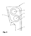
- FIG. 3 shows the lower bead ring of the pneumatic spring bellows of the pneumatic spring device according to the invention, the bead ring being fastened to the unsprung subframe;
- FIG. 4 shows the upper bead ring of the pneumatic spring bellows of the pneumatic spring device according to the invention, the bead ring being fastened to the chassis;
- FIG. 5 is a schematic showing the lower bead ring of the pneumatic spring bellows wherein at least one of the core rings is configured as a wound core.
- FIG. 1 shows the front part of a short-range rail vehicle 1 with a subframe or bogie 2 which is connected to the chassis 4 of the rail vehicle 1 via a pneumatic spring device 3 according to the invention.
- FIG. 2 shows the pneumatic spring device 3 in an enlarged section view.
- FIG. 2 shows the pneumatic spring bellows 5 which is arranged between sprung chassis 4 and an unsprung subframe.
- the pneumatic spring bellows is provided with reinforcement elements embedded in the bellows material and, at both ends, has a bead ring ( 6 , 7 ) for clamping the pneumatic spring bellows to correspondingly designed stop rings ( 8 , 9 ) of the chassis 4 and the unsprung subframe, that is, bogie 2 .
- FIG. 3 shows, in an enlarged view, the lower bead ring 7 of the pneumatic spring bellows 5 with the bead ring being fastened to the unsprung bogie 2 .
- the bead ring 7 is provided with a core made of two core rings 10 and 11 positioned separately in the bead ring.
- the reinforcement elements 12 are guided in an S-shaped configuration between the core rings 10 and 11 and loop around the latter.
- FIG. 4 shows, in an enlarged view, the upper bead ring 6 of the pneumatic spring bellows 5 with the bead ring being fastened to the chassis 4 .
- the bead ring 6 is also provided with a core made of two core rings 13 and 14 positioned separately in the bead ring.
- the reinforcement elements 12 are guided in an S-shaped configuration between the core rings 13 and 14 and loop around the latter.
- FIGS. 3 and 4 also show that, starting from the central part of the pneumatic spring bellows 5 , the reinforcement elements 12 enter into the S-shaped looping around of the core rings ( 10 , 11 , 13 , 14 ) at a distance from the clamping region ( 15 , 16 ) formed in each case between the bead ring ( 6 , 7 ) and stop ring ( 8 , 9 ).
- FIG. 5 shows an embodiment wherein at least one of the core rings ( 10 , 11 , 13 , 14 ) is configured as a wound core.
- a filament 10 a is wound many times about the bellows blank to form the core cross section.
- the filament 10 a is made, for example, of plastic or even of metal, that is, a thin wire.
Landscapes
- Engineering & Computer Science (AREA)
- General Engineering & Computer Science (AREA)
- Mechanical Engineering (AREA)
- Vehicle Body Suspensions (AREA)
- Fluid-Damping Devices (AREA)
- Springs (AREA)
Applications Claiming Priority (4)
| Application Number | Priority Date | Filing Date | Title |
|---|---|---|---|
| DE201010000290 DE102010000290A1 (de) | 2010-02-03 | 2010-02-03 | Luftfedereinrichtung eines Schienenfahrzeuges |
| DE102010000290 | 2010-02-03 | ||
| DE102010000290.9 | 2010-02-03 | ||
| PCT/EP2010/068705 WO2011095242A1 (de) | 2010-02-03 | 2010-12-02 | Luftfedereinrichtung eines schienenfahrzeuges |
Related Parent Applications (1)
| Application Number | Title | Priority Date | Filing Date |
|---|---|---|---|
| PCT/EP2010/068705 Continuation WO2011095242A1 (de) | 2010-02-03 | 2010-12-02 | Luftfedereinrichtung eines schienenfahrzeuges |
Publications (2)
| Publication Number | Publication Date |
|---|---|
| US20120313303A1 US20120313303A1 (en) | 2012-12-13 |
| US8882087B2 true US8882087B2 (en) | 2014-11-11 |
Family
ID=43646194
Family Applications (1)
| Application Number | Title | Priority Date | Filing Date |
|---|---|---|---|
| US13/562,027 Active 2030-12-27 US8882087B2 (en) | 2010-02-03 | 2012-07-30 | Pneumatic spring device for a rail vehicle |
Country Status (5)
| Country | Link |
|---|---|
| US (1) | US8882087B2 (de) |
| EP (1) | EP2531745B1 (de) |
| CN (1) | CN102741581B (de) |
| DE (1) | DE102010000290A1 (de) |
| WO (1) | WO2011095242A1 (de) |
Families Citing this family (8)
| Publication number | Priority date | Publication date | Assignee | Title |
|---|---|---|---|---|
| DE102008055509A1 (de) * | 2008-12-11 | 2010-06-17 | Contitech Luftfedersysteme Gmbh | Luftfeder |
| US9261156B2 (en) * | 2013-02-14 | 2016-02-16 | Firestone Industrial Products Company, Llc | Flexible spring members as well as gas spring assemblies and methods of manufacture including same |
| DE102014215025B4 (de) | 2014-07-31 | 2024-05-08 | Contitech Luftfedersysteme Gmbh | Luftfeder sowie Schienenfahrzeug mit einer Luftfeder |
| US10907461B1 (en) | 2015-02-12 | 2021-02-02 | Raymond C. Sherry | Water hydration system |
| DE202015008448U1 (de) * | 2015-11-30 | 2016-01-22 | Contitech Luftfedersysteme Gmbh | Balgluftfeder mit versenkten Wulstringschrauben |
| CN105502202A (zh) * | 2016-02-02 | 2016-04-20 | 张栗 | 多曲面一端开口的橡胶气囊 |
| RU2696888C1 (ru) * | 2018-11-06 | 2019-08-07 | федеральное государственное унитарное предприятие "Федеральный научно-производственный центр "Прогресс" (ФГУП "ФНПЦ "Прогресс") | Резинокордный пневматический элемент |
| DE102019215987A1 (de) * | 2019-10-17 | 2021-04-22 | Contitech Luftfedersysteme Gmbh | Federbalg einer Luftfeder und Verfahren zu dessen Herstellung |
Citations (17)
| Publication number | Priority date | Publication date | Assignee | Title |
|---|---|---|---|---|
| US3549142A (en) * | 1968-11-29 | 1970-12-22 | Goodyear Tire & Rubber | Fluid springs |
| DE2108694A1 (de) | 1971-02-24 | 1972-08-31 | Continental Gummi-Werke Ag, 3000 Hannover | Luftfederbalg |
| US3897941A (en) * | 1974-03-28 | 1975-08-05 | Goodyear Tire & Rubber | Reinforced fluid spring |
| SU1333911A1 (ru) | 1983-12-15 | 1987-08-30 | Предприятие П/Я А-3404 | Резинокордный элемент |
| DE4011517A1 (de) | 1990-04-10 | 1991-10-17 | Continental Ag | Luftfederbalg fuer schienenfahrzeuge |
| US5253850A (en) * | 1992-06-04 | 1993-10-19 | The Goodyear Tire & Rubber Company | Airspring with non-molded-in bead |
| US5382006A (en) | 1993-09-29 | 1995-01-17 | The Goodyear Tire & Rubber Company | Airspring piston and airspring assembly |
| US5535994A (en) * | 1993-11-30 | 1996-07-16 | The Goodyear Tire & Rubber Company | Composite air spring piston |
| US5580033A (en) * | 1995-04-07 | 1996-12-03 | The Goodyear Tire & Rubber Company | Bellows type air spring and method of making same |
| US5934652A (en) * | 1998-05-28 | 1999-08-10 | The Goodyear Tire & Rubber Company | Air spring bumper and method of mounting |
| US6264178B1 (en) * | 2000-06-13 | 2001-07-24 | The Goodyear Tire & Rubber Company | Molded air sleeves |
| US6460836B1 (en) * | 1997-03-13 | 2002-10-08 | The Goodyear Tire & Rubber Company | Press together air spring |
| EP1593873A1 (de) | 2004-05-03 | 2005-11-09 | ContiTech Luftfedersysteme GmbH | Luftfeder mit Rollbalg, Abrollkolben und Spannteller |
| US20070257409A1 (en) | 2004-10-15 | 2007-11-08 | Axel Szyszka | Air Spring |
| US20110266728A1 (en) * | 2008-12-11 | 2011-11-03 | Christoph Bank | Air spring |
| US8403307B2 (en) * | 2007-08-30 | 2013-03-26 | Firestone Industrial Products Company, Llc | Gas spring assembly and method of manufacture |
| US20130270753A1 (en) * | 2010-12-10 | 2013-10-17 | Contitech Luftfedersysteme Gmbh | Air spring for a commercial vehicle including a rolling-lobe flexible member of elastomeric material having ends provided with respective fastening beads |
Family Cites Families (5)
| Publication number | Priority date | Publication date | Assignee | Title |
|---|---|---|---|---|
| JPS5563027U (de) * | 1978-10-25 | 1980-04-30 | ||
| JPS5563027A (en) * | 1978-11-04 | 1980-05-12 | Sumitomo Metal Ind Ltd | Air spring |
| JPS6474333A (en) * | 1987-09-11 | 1989-03-20 | Sumitomo Electric Industries | Reinforcement structure of rubber bellows |
| JP4852204B2 (ja) * | 2001-09-21 | 2012-01-11 | 東洋ゴム工業株式会社 | 鉄道車両用空気ばね装置 |
| CN1788171A (zh) * | 2003-06-04 | 2006-06-14 | 凤凰股份有限公司 | 弹簧装置,特别是用于有轨车辆领域的弹簧装置 |
-
2010
- 2010-02-03 DE DE201010000290 patent/DE102010000290A1/de not_active Withdrawn
- 2010-12-02 CN CN201080063085.8A patent/CN102741581B/zh active Active
- 2010-12-02 WO PCT/EP2010/068705 patent/WO2011095242A1/de not_active Ceased
- 2010-12-02 EP EP10787410.9A patent/EP2531745B1/de active Active
-
2012
- 2012-07-30 US US13/562,027 patent/US8882087B2/en active Active
Patent Citations (18)
| Publication number | Priority date | Publication date | Assignee | Title |
|---|---|---|---|---|
| US3549142A (en) * | 1968-11-29 | 1970-12-22 | Goodyear Tire & Rubber | Fluid springs |
| DE2108694A1 (de) | 1971-02-24 | 1972-08-31 | Continental Gummi-Werke Ag, 3000 Hannover | Luftfederbalg |
| US3895787A (en) * | 1971-02-24 | 1975-07-22 | Continental Gummi Werke Ag | Railway air spring bellows |
| US3897941A (en) * | 1974-03-28 | 1975-08-05 | Goodyear Tire & Rubber | Reinforced fluid spring |
| SU1333911A1 (ru) | 1983-12-15 | 1987-08-30 | Предприятие П/Я А-3404 | Резинокордный элемент |
| DE4011517A1 (de) | 1990-04-10 | 1991-10-17 | Continental Ag | Luftfederbalg fuer schienenfahrzeuge |
| US5253850A (en) * | 1992-06-04 | 1993-10-19 | The Goodyear Tire & Rubber Company | Airspring with non-molded-in bead |
| US5382006A (en) | 1993-09-29 | 1995-01-17 | The Goodyear Tire & Rubber Company | Airspring piston and airspring assembly |
| US5535994A (en) * | 1993-11-30 | 1996-07-16 | The Goodyear Tire & Rubber Company | Composite air spring piston |
| US5580033A (en) * | 1995-04-07 | 1996-12-03 | The Goodyear Tire & Rubber Company | Bellows type air spring and method of making same |
| US6460836B1 (en) * | 1997-03-13 | 2002-10-08 | The Goodyear Tire & Rubber Company | Press together air spring |
| US5934652A (en) * | 1998-05-28 | 1999-08-10 | The Goodyear Tire & Rubber Company | Air spring bumper and method of mounting |
| US6264178B1 (en) * | 2000-06-13 | 2001-07-24 | The Goodyear Tire & Rubber Company | Molded air sleeves |
| EP1593873A1 (de) | 2004-05-03 | 2005-11-09 | ContiTech Luftfedersysteme GmbH | Luftfeder mit Rollbalg, Abrollkolben und Spannteller |
| US20070257409A1 (en) | 2004-10-15 | 2007-11-08 | Axel Szyszka | Air Spring |
| US8403307B2 (en) * | 2007-08-30 | 2013-03-26 | Firestone Industrial Products Company, Llc | Gas spring assembly and method of manufacture |
| US20110266728A1 (en) * | 2008-12-11 | 2011-11-03 | Christoph Bank | Air spring |
| US20130270753A1 (en) * | 2010-12-10 | 2013-10-17 | Contitech Luftfedersysteme Gmbh | Air spring for a commercial vehicle including a rolling-lobe flexible member of elastomeric material having ends provided with respective fastening beads |
Non-Patent Citations (1)
| Title |
|---|
| International Search Report dated Mar. 21, 2011 of international application PCT/EP 2010/068705 on which this application is based. |
Also Published As
| Publication number | Publication date |
|---|---|
| CN102741581A (zh) | 2012-10-17 |
| US20120313303A1 (en) | 2012-12-13 |
| CN102741581B (zh) | 2016-01-27 |
| DE102010000290A1 (de) | 2011-08-04 |
| EP2531745B1 (de) | 2013-11-20 |
| EP2531745A1 (de) | 2012-12-12 |
| WO2011095242A1 (de) | 2011-08-11 |
Similar Documents
| Publication | Publication Date | Title |
|---|---|---|
| US8882087B2 (en) | Pneumatic spring device for a rail vehicle | |
| US3897941A (en) | Reinforced fluid spring | |
| US8403307B2 (en) | Gas spring assembly and method of manufacture | |
| EP1331108A2 (de) | Wulstkern mit Leichtmetall-Seele | |
| US10040323B2 (en) | Pneumatic tire with bead reinforcing elements at least partially formed from carbon fibers | |
| US10953690B2 (en) | Adapter for a rolling assembly and rolling assembly comprising same | |
| JP2012153235A (ja) | 農業用タイヤ | |
| US9944143B2 (en) | Spring pad for vehicle suspension | |
| US9956827B2 (en) | Agricultural vehicle tire carcass reinforcement | |
| EP3725565B1 (de) | Luftreifen mit einem wulstreiter mit mehreren gummischichten | |
| US7784771B2 (en) | Spring body for gas spring assembly and method of forming same | |
| US10752059B2 (en) | Tire with greater resistance to unseating | |
| JP4598504B2 (ja) | 重荷重用空気入りラジアルタイヤ | |
| DE102013108694A1 (de) | Anschluss- und Verstärkungsquerschnitt für ein balgartiges Tragelement | |
| KR20230126278A (ko) | 시어 밴드를 구비한 비공기입 타이어 | |
| KR102254474B1 (ko) | 보강부재를 구비한 공기입 타이어 | |
| KR20200124344A (ko) | 공기입타이어 | |
| US20220379663A1 (en) | Crown Reinforcement of a Tire for a Heavy Construction Plant Vehicle | |
| KR102113077B1 (ko) | 공기입 타이어 | |
| US20170297382A1 (en) | Tire Having Greater Resistance To Unseating | |
| US20030075255A1 (en) | Pneumatic vehicle tire | |
| JP6749342B2 (ja) | ローリングアセンブリ用のアダプタおよびそれを備えるローリングアセンブリ | |
| KR101852273B1 (ko) | 공기입타이어 | |
| JPS583844B2 (ja) | 空気入りタイヤ | |
| JP2021098430A (ja) | 空気入りタイヤ |
Legal Events
| Date | Code | Title | Description |
|---|---|---|---|
| AS | Assignment |
Owner name: CONTITECH LUFTFEDERSYSTEME GMBH, GERMANY Free format text: ASSIGNMENT OF ASSIGNORS INTEREST;ASSIGNORS:GEDENK, VOLKER;HESSE, BERND;SIGNING DATES FROM 20120801 TO 20120806;REEL/FRAME:028845/0301 |
|
| STCF | Information on status: patent grant |
Free format text: PATENTED CASE |
|
| FEPP | Fee payment procedure |
Free format text: PAYOR NUMBER ASSIGNED (ORIGINAL EVENT CODE: ASPN); ENTITY STATUS OF PATENT OWNER: LARGE ENTITY |
|
| MAFP | Maintenance fee payment |
Free format text: PAYMENT OF MAINTENANCE FEE, 4TH YEAR, LARGE ENTITY (ORIGINAL EVENT CODE: M1551) Year of fee payment: 4 |
|
| MAFP | Maintenance fee payment |
Free format text: PAYMENT OF MAINTENANCE FEE, 8TH YEAR, LARGE ENTITY (ORIGINAL EVENT CODE: M1552); ENTITY STATUS OF PATENT OWNER: LARGE ENTITY Year of fee payment: 8 |
|
| AS | Assignment |
Owner name: CONTITECH DEUTSCHLAND GMBH, GERMANY Free format text: ASSIGNMENT OF ASSIGNORS INTEREST;ASSIGNOR:CONTITECH LUFTFEDERSYSTEME GMBH;REEL/FRAME:069259/0540 Effective date: 20241112 Owner name: CONTITECH DEUTSCHLAND GMBH, GERMANY Free format text: ASSIGNMENT OF ASSIGNOR'S INTEREST;ASSIGNOR:CONTITECH LUFTFEDERSYSTEME GMBH;REEL/FRAME:069259/0540 Effective date: 20241112 |