US8872476B2 - Charging management system and charger with the same - Google Patents
Charging management system and charger with the same Download PDFInfo
- Publication number
- US8872476B2 US8872476B2 US13/362,853 US201213362853A US8872476B2 US 8872476 B2 US8872476 B2 US 8872476B2 US 201213362853 A US201213362853 A US 201213362853A US 8872476 B2 US8872476 B2 US 8872476B2
- Authority
- US
- United States
- Prior art keywords
- signal
- charging
- battery
- output port
- output
- Prior art date
- Legal status (The legal status is an assumption and is not a legal conclusion. Google has not performed a legal analysis and makes no representation as to the accuracy of the status listed.)
- Expired - Fee Related, expires
Links
Images


Classifications
-
- H—ELECTRICITY
- H02—GENERATION; CONVERSION OR DISTRIBUTION OF ELECTRIC POWER
- H02J—CIRCUIT ARRANGEMENTS OR SYSTEMS FOR SUPPLYING OR DISTRIBUTING ELECTRIC POWER; SYSTEMS FOR STORING ELECTRIC ENERGY
- H02J7/00—Circuit arrangements for charging or depolarising batteries or for supplying loads from batteries
- H02J7/02—Circuit arrangements for charging or depolarising batteries or for supplying loads from batteries for charging batteries from ac mains by converters
- H02J7/04—Regulation of charging current or voltage
-
- H—ELECTRICITY
- H02—GENERATION; CONVERSION OR DISTRIBUTION OF ELECTRIC POWER
- H02J—CIRCUIT ARRANGEMENTS OR SYSTEMS FOR SUPPLYING OR DISTRIBUTING ELECTRIC POWER; SYSTEMS FOR STORING ELECTRIC ENERGY
- H02J7/00—Circuit arrangements for charging or depolarising batteries or for supplying loads from batteries
- H02J7/007—Regulation of charging or discharging current or voltage
- H02J7/00712—Regulation of charging or discharging current or voltage the cycle being controlled or terminated in response to electric parameters
- H02J7/00714—Regulation of charging or discharging current or voltage the cycle being controlled or terminated in response to electric parameters in response to battery charging or discharging current
-
- H—ELECTRICITY
- H01—ELECTRIC ELEMENTS
- H01M—PROCESSES OR MEANS, e.g. BATTERIES, FOR THE DIRECT CONVERSION OF CHEMICAL ENERGY INTO ELECTRICAL ENERGY
- H01M10/00—Secondary cells; Manufacture thereof
- H01M10/42—Methods or arrangements for servicing or maintenance of secondary cells or secondary half-cells
- H01M10/425—Structural combination with electronic components, e.g. electronic circuits integrated to the outside of the casing
- H01M10/4257—Smart batteries, e.g. electronic circuits inside the housing of the cells or batteries
-
- H—ELECTRICITY
- H02—GENERATION; CONVERSION OR DISTRIBUTION OF ELECTRIC POWER
- H02J—CIRCUIT ARRANGEMENTS OR SYSTEMS FOR SUPPLYING OR DISTRIBUTING ELECTRIC POWER; SYSTEMS FOR STORING ELECTRIC ENERGY
- H02J7/00—Circuit arrangements for charging or depolarising batteries or for supplying loads from batteries
- H02J7/007—Regulation of charging or discharging current or voltage
- H02J7/00712—Regulation of charging or discharging current or voltage the cycle being controlled or terminated in response to electric parameters
- H02J7/007182—Regulation of charging or discharging current or voltage the cycle being controlled or terminated in response to electric parameters in response to battery voltage
-
- Y—GENERAL TAGGING OF NEW TECHNOLOGICAL DEVELOPMENTS; GENERAL TAGGING OF CROSS-SECTIONAL TECHNOLOGIES SPANNING OVER SEVERAL SECTIONS OF THE IPC; TECHNICAL SUBJECTS COVERED BY FORMER USPC CROSS-REFERENCE ART COLLECTIONS [XRACs] AND DIGESTS
- Y02—TECHNOLOGIES OR APPLICATIONS FOR MITIGATION OR ADAPTATION AGAINST CLIMATE CHANGE
- Y02B—CLIMATE CHANGE MITIGATION TECHNOLOGIES RELATED TO BUILDINGS, e.g. HOUSING, HOUSE APPLIANCES OR RELATED END-USER APPLICATIONS
- Y02B40/00—Technologies aiming at improving the efficiency of home appliances, e.g. induction cooking or efficient technologies for refrigerators, freezers or dish washers
-
- Y—GENERAL TAGGING OF NEW TECHNOLOGICAL DEVELOPMENTS; GENERAL TAGGING OF CROSS-SECTIONAL TECHNOLOGIES SPANNING OVER SEVERAL SECTIONS OF THE IPC; TECHNICAL SUBJECTS COVERED BY FORMER USPC CROSS-REFERENCE ART COLLECTIONS [XRACs] AND DIGESTS
- Y02—TECHNOLOGIES OR APPLICATIONS FOR MITIGATION OR ADAPTATION AGAINST CLIMATE CHANGE
- Y02E—REDUCTION OF GREENHOUSE GAS [GHG] EMISSIONS, RELATED TO ENERGY GENERATION, TRANSMISSION OR DISTRIBUTION
- Y02E60/00—Enabling technologies; Technologies with a potential or indirect contribution to GHG emissions mitigation
- Y02E60/10—Energy storage using batteries
Definitions
- the present invention generally relates to the field of battery, and more particularly to a charging management system for charging battery and a charger with the same.
- Battery management systems usually take charge of calculating voltage levels of individual cells in a battery to protect the battery from being overcharged or over-discharged, and monitoring signal transmission inside/outside of the battery. In existing technologies, nearly all of battery-driving products need the battery management systems.
- battery management systems are used to balance power of the battery units.
- power balancing methods there are two types of power balancing methods: one is called passive power balance and the other is called active power balance.
- passive power balance method redundant power of the battery units is transformed to heat by resistances and then dissipated.
- active power balance method adopts a power transition manner, in which redundant power of the battery modules is transmitted to corresponding battery units with less power.
- Such active power balance method can be realized either in charging or discharging to meet broader needs.
- the conventional battery management systems with the active power balance method employ DC/DC converters to convert the voltage of all the battery units of the battery pack so as to charge the given battery units needed to be charged.
- DC/DC converters to convert the voltage of all the battery units of the battery pack so as to charge the given battery units needed to be charged.
- such process needs long balance time.
- the conventional active power balance method requires many judging and starting steps so that efficiency thereof is low as well.
- a charger can charge the battery under two charging modes, one is called normal charge mode and the other is called variable charge mode.
- normal charge mode high charging current is adopted at the beginning stage so as to quickly charge the battery, and when the battery is charged near saturation, the charging current is reduced so as to slowly charge the battery.
- variable charge mode two charging ports are usually needed for switching between the stages.
- variable charge mode only one single charging port is needed for charging the battery with a variable current.
- the battery management systems with the passive power balance method, there is no communication between the battery management systems and the exterior chargers, so the battery management systems can only be set to one charging mode, which is not compatible to the chargers under the other charging mode.
- the present invention provides a charging management system for receiving a signal from a battery to be charged, and controlling a charging circuit of a charger so as to charge the battery to be charged according to the received signal.
- the charging management system includes a first signal-output port for outputting a first control signal representing a first charging current to the charging circuit, a second signal-output port for outputting a second control signal representing a second charging current to the charging circuit, a third signal-output port for outputting a third control signal representing a variable third charging current to the charging circuit, and a controller electrically connected with the first, second and third signal-output ports.
- the controller controls the charging management system to operate under at least one of a first mode and a second mode.
- the controller selectively controls the outputs of the first signal-output port and the second signal-output port. In the second mode, the controller only controls the output of the third signal-output port.
- a charger with the above-described charging management system is also disclosed.
- the present invention relates to a charging management system for receiving a signal from a battery to be charged, and controlling a charging circuit of a charger so as to charge the battery to be charged according to the received signal.
- the charging management system in one embodiment includes a first signal-output port adapted for outputting a first control signal representing a first charging current to the charging circuit, a second signal-output port adapted for outputting a second control signal representing a second charging current to the charging circuit, a third signal-output port adapted for outputting a third control signal representing a variable third charging current to the charging circuit, and a controller electrically connected with the first, second and third signal-output ports.
- the controller controls the charging management system to operate in at least one of a first mode and a second mode.
- the controller In the first mode, the controller alternately controls the outputs of the first signal-output port and the second signal-output port.
- the controller In the second mode, the controller only controls the output of the third signal-output port.
- the controller when operating in the first mode, controls the first signal-output port to output the first control signal, and then controls the second signal-output port to output the second control signal. Further, when the battery to be charged is saturated, the controller controls the first and second signal-output ports not to output any control signal.
- the charging management system further includes a first switch electrically connected between the controller and the first signal-output port, and a second switch electrically connected between the controller and the second signal-output port.
- the controller controls the first and second signal-output ports to output or not to output the first and second control signals.
- each of the first switch and the second switch includes an optical coupling relay.
- the second charging current when operating in the first mode, is far lower than the first charging current so that the first charging current is adapted to quickly charge the battery to be charged in a quick-charge mode, and the second charging current is adapted to slowly charge the battery to be charged in a trickle-charge mode when the battery to be charged is charged near saturation.
- the controller when operating in the second mode, controls the third signal-output port by outputting a Pulse Width Modulation (PWM) signal to the third signal-output port.
- PWM Pulse Width Modulation
- the charging management system further includes an amplifier electrically connected between the controller and the third signal-output port to amplify the PWM signal.
- the charging management system further includes a signal-input port for receiving communication signal from the battery to be charged, where the controller is adapted for receiving an input signal of the signal-input port and controlling the first, second and third signal-output ports according to the input signal.
- the charging management system further comprises a power port adapted for receiving electric power from the battery to be charged, and a voltage conversion circuit electrically connected between the power port and the controller.
- the power port includes a positive pole and a negative pole, and each of the positive pole and the negative pole includes two conductive contacts.
- the third charging current when operating in the second mode, when charging of the battery to be charged begins, the third charging current is high for quick charging, and when the battery to be charged is charged near saturation, the third charging current is gradually reduced until the battery to be charged is saturated.
- the present invention relates to a charger.
- the charger in one embodiment includes a charging management system and a charging circuit.
- the charging management system includes a first signal-output port for outputting a first control signal representing a first charging current, a second signal-output port for outputting a second control signal representing a second charging current, a third signal-output port for outputting a third control signal representing a variable third charging current, and a controller electrically connected with the first, second and third signal-output ports to control the charging management system to operate under at least one of first and second modes.
- the controller alternately controls the first signal-output port to output the first control signal and the second signal-output port to output the second control signal as a control signal.
- the controller In the second mode, the controller only controls the third signal-output port to output the third control signal as the control signal.
- the charging circuit is adapted for receiving the control signal outputted from the charging management system and outputting the corresponding first, second or third charging current to charge the battery to be charged according to the control signal.
- the controller when operating in the first mode, controls the first signal-output port to output the first control signal as the control signal, and then the controller controls the second signal-output port to output the second control signal as the control signal.
- the controller when the battery to be charged is saturated, controls the first and second signal-output ports not to output any control signal.
- the charging management system includes a first switch electrically connected between the controller and the first signal-output port, and a second switch electrically connected between the controller and the second signal-output port. Through controlling the ON/OFF status of the first or the second switches, the controller controls the first signal-output port and the second signal-output port to output or not to output the first and second control signals.
- the second charging current when operating in the first mode, is far lower than the first charging current so that the first charging current is adapted to quickly charge the battery to be charged in a quick-charge mode, and the second charging current is adapted to slowly charge the battery to be charged in a trickle-charge mode when the battery to be charged is charged near saturation.
- the third charging current when operating in the second mode, when charging of the battery to be charged begins, the third charging current is high for quick charging, and when the battery to be charged is charged near saturation, the third charging current is gradually reduced until the battery to be charged is saturated.
- the controller when operating in the second mode, controls the third signal-output port by outputting a Pulse Width Modulation (PWM) signal to the third signal-output port.
- PWM Pulse Width Modulation
- the charging management system further includes an amplifier electrically connected between the controller and the third signal-output port to amplify the PWM signal.
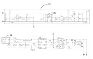
- FIG. 1 is a schematic diagram of a charging management system showing relationships between a charging circuit and a battery management system in accordance with a first embodiment of the present invention
- FIG. 2A ?? FIG. 2 E is schematic diagram of the charging management system in accordance with an illustrated embodiment of the present invention.
- first, second, third etc. may be used herein to describe various elements, components, regions, parts and/or sections, these elements, components, regions, parts and/or sections should not be limited by these terms. These terms are only used to distinguish one element, component, region, part or section from another element, component, region, layer or section. Thus, a first element, component, region, part or section discussed below could be termed a second element, component, region, layer or section without departing from the teachings of the present invention.
- relative terms such as “lower” or “bottom” and “upper” or “top,” may be used herein to describe one element's relationship to another element as illustrated in the Figures. It will be understood that relative terms are intended to encompass different orientations of the device in addition to the orientation depicted in the Figures. For example, if the device in one of the figures is turned over, elements described as being on the “lower” side of other elements would then be oriented on “upper” sides of the other elements. The exemplary term “lower”, can therefore, encompasses both an orientation of “lower” and “upper,” depending of the particular orientation of the figure.
- “around”, “about” or “approximately” shall generally mean within 20 percent, preferably within 10 percent, and more preferably within 5 percent of a given value or range. Numerical quantities given herein are approximate, meaning that the term “around”, “about” or “approximately” can be inferred if not expressly stated.
- this invention in one aspect, relates to a charging management system for charging battery, and a charger with such a charging management system.
- a battery system 400 is schematically shown according to one embodiment of the present invention.
- the battery system 400 includes a battery management system 42 and a battery 41 that includes multiple battery units electrically connected to each other in series.
- the battery system 400 or the battery 41 is the battery that needs to be charged.
- the multiple battery units can be grouped, either in the same number or in different numbers, to form multiple battery modules.
- a charger 200 has a charging management system adapted for receiving a signal from the battery system 400 , and a charging circuit 300 adapted for charging the battery to be charged according to the received signal, under the control of the charging management system.
- the charging management system includes a first signal-output port 11 , a second signal-output port 12 , a third signal-output port 13 and a controller 14 .
- the first signal-output port 11 , the second signal-output port 12 and the third signal-output port 13 are all adapted for outputting charge-current control signals, which represent certain current values, to the charging circuit 300 , so that the charging circuit 300 is capable of selecting different charging currents for charging the battery 41 of the battery system 400 .
- the differences among them are that the first signal-output port 11 is adapted for outputting a first control signal which represents a first charging current to the charging circuit 300 , the second signal-output port 12 is adapted for outputting a second control signal which represents a second charging current lower than the first charging current to the charging circuit 300 , and the third signal-output port 13 is adapted for outputting a third control signal which represents a variable third charging current to the charging circuit 300 .
- the current value of the second charging current is far lower than the first charging current so that the first charging current is adapted to quickly charge the battery 41 in a quick-charge mode, because a higher charging current easily realizes better charging rate so as to improve charging efficiency.
- the second charging current is adapted to slowly charge the battery 41 in a trickle-charge mode when the battery 41 is charged to be near the saturation.
- the third charging current is variable according to the state of the battery to be charged. For example, when charging of the battery 41 begins, the third charging current is high for quick charging, and when a part of the battery units of the battery 41 is near saturation, the third charging current is gradually reduced, and as more battery units of the battery 41 are saturated, the third charging current is further reduced. The third charging current is gradually reduced until the battery 41 is saturated.
- the reason for this arrangement is that, during the charging process, the voltage Vcell of the battery 41 detected by the battery management system 42 of the battery system 400 essentially includes the voltage Vcap of the battery core and the voltage difference Vres generated by the internal resistance of the battery core. The voltage Vcell equals to the sum of the voltage Vcap and the voltage difference Vres. Further, high charging current would increase the voltage difference Vres resulted from the internal resistance of the battery core.
- the detected voltage of the battery 41 is about 3.8V. If the charging current is reduced to about 2 A at this time, the corresponding detected voltage of the battery 41 becomes about 3.5V. It should be noted that, with a high charging current, the detected voltage of the battery 41 would become less accurate to reflect the actual charging state of the battery 41 . For this reason, the influence in detecting the voltage of the battery 41 can be reduced by gradually reducing the third charging current as far as possible, thereby ensuring reliability of the battery charging and improving charging efficiency.
- the controller 14 is electrically connected with the first, second and third signal-output ports 11 , 12 and 13 , and controls the charging management system to operate at least in one of a first mode and a second mode.
- the first mode and the second mode respectively correspond to two existing charging modes of the chargers 200 .
- more modes can be provided to correspond to more types of the chargers 200 .
- the controller 14 includes a Micro Controller Unit (MCU) having a Central Processing Unit (CPU), a Read-Only Memory (ROM) and a Random Access Memory (RAM), a timing module, an A/D converter, and multiple input/output ports.
- MCU Micro Controller Unit
- CPU Central Processing Unit
- ROM Read-Only Memory
- RAM Random Access Memory
- the controller 14 can also use other types of integrated circuits, such as Application Specific Integrated Circuit (ASIC) and Field Programmable Gate Array (FPGA), and so on.
- ASIC Application Specific Integrated Circuit
- FPGA Field Programmable Gate Array
- the controller 14 corresponds to the first mode. In this case, the controller 14 selectively controls the first signal-output port 11 to output the first control signal and the second signal-output port 12 to output the second control signal as a control signal.
- the controller 14 controls the first signal-output port 11 to output the first control signal so that the charger 200 is adapted to quickly charge the battery 41 under the higher first charging current.
- the battery management system 42 detects that the battery 41 is near saturation, the communication signal of the battery to be charged is transmitted to the charging management system via a signal-input port 16 . Thereafter, the controller 14 controls the second signal-output port 12 to output the second control signal so that the charger 200 is adapted to slowly charge the battery 41 , according to the acquired communication signal representing the charging status of the battery 41 .
- the controller 14 controls the first signal-output port 11 and the second signal-output port 12 so that neither outputs any charge-current control signal. In other words, the charging circuit 300 stops charging the battery 41 when the battery 41 gets saturated.
- the charging management system further includes a first switch 151 electrically connected between the controller 14 and the first signal-output port 11 , and a second switch 152 electrically connected between the controller 14 and the second signal-output port 12 .
- the controller 14 controls the first signal-output port 11 and the second signal-output port 12 to output or not to output the first and second control signals, respectively.
- the first and second switches 151 and 152 include triodes, Silicon Controlled Rectifiers (SCRs), relay switches, Metallic Oxide Semiconductor Field Effect Transistors (MOSFETs), or the like.
- the first and second switches 151 and 152 include first and second optical coupling relays P 1 -A and P 1 -B, respectively. Through controlling the ON/OFF status of the MOSFET set in the first or second optical coupling relays P 1 -A or P 1 -B, the first or second switches 151 or 152 can be therefore controlled to achieve the ON/OFF purpose accordingly.
- the controller 14 corresponds to the second mode. In this case, the controller 14 only controls the third signal-output port 13 to output the third control signal. Specifically, the controller 14 controls the third signal-output port 13 by outputting a PWM signal into the third signal-output port 13 . Further, the PWM signal can be amplified by an amplifier 19 which is electrically connected between the controller 14 and the third signal-output port 13 , in order to keep charging-control accurateness.
- the controller 14 controls the third signal-output port 13 to output the third control signal so as to quickly charge the battery 41 under a high current.
- the battery management system 42 detects that the battery 41 or at least a part of the battery units of the battery 41 reach saturation, a communication signal generated by the battery 41 is transmitted to the charging management system via the corresponding signal-input port.
- the controller 14 controls the third signal-output port 13 to output a reduced third charging current according to the communication signal.
- the third charging current is slightly lower than the former current so that the voltage difference Vres generated by the internal resistance of the battery core is reduced because of the reduced third charging current. As a result, the battery units not saturated can be further charged.
- the third charging current is gradually reduced until the voltage of the battery 41 is not reduced along with the reduction of the third charging current, or until the reduced voltage resulted from the reduction of the third charging current is lower than a certain voltage threshold.
- the charging management system further includes a power port 17 and a voltage conversion circuit 18 .
- the power port 17 is adapted for receiving electric power from the battery system 400 .
- the voltage conversion circuit 18 is electrically connected between the power port 17 and the controller 14 .
- the electric power required for operation of the whole charging management system including the controller 14 is provided by the battery system 400 .
- the voltage conversion circuit 18 is adapted for reducing and stabilizing large output current outputted by the battery 41 to lower working current for the charging management system, via a DC/DC converter 181 and a voltage-stabilizing circuit of the voltage conversion circuit 18 .
- the advantage of this arrangement is that controller suppliers do not need to design additional power-supply circuits, thereby reducing design and manufacture costs accordingly.
- the power port 17 includes a positive pole 171 having two conductive contacts J 1 - 3 and J 1 - 4 , and a negative pole 172 having two conductive contacts J 1 - 1 and J 1 - 2 .
- the functions of the two conductive contacts J 1 - 3 and J 1 - 4 of the positive pole 171 are the same, and the functions of the two conductive contacts of the negative pole 172 J 1 - 1 and J 1 - 2 are the same as well.
- the charging management system can still operate so as to prevent the battery management system 42 from being damaged.
- the battery management system 42 adopts the passive power-consumption balance method as described in detail in the above-described embodiments, in some other embodiments, the battery management system 42 can also adopt the active power-consumption balance method to achieve the same function of the present invention.
- the above-described charging management system is adopted thereto, and the charging management system is electrically connected with the charging circuit 300 .
- the charging circuit 300 receives the control signal from the charging management system and then outputs the corresponding charging current provided for charging the battery system 400 .
- the charging management system of the present invention is capable of alternately operating in at least two different modes.
- the charging management system adopts the first mode.
- the first mode through control of the first control signal representing the first charging current and the second control signal representing the second charging current, different charging functions including quick charging, trickle charging and stop charging can be achieved.
- the charging management system adopts the second mode.
- the third control signal which represents the variable third charging current
- the charger 200 can realize flexible charging of the battery 41 in a current-variable charging way. In this case, even if the chargers 200 have different operation modes, all of them can be adapted for effectually charging the battery system 400 having the battery management system 42 , and there is no need of adjusting the battery management system 42 of the battery system 400 .
Landscapes
- Engineering & Computer Science (AREA)
- Power Engineering (AREA)
- Charge And Discharge Circuits For Batteries Or The Like (AREA)
- Secondary Cells (AREA)
Abstract
Description
Claims (19)
Applications Claiming Priority (3)
| Application Number | Priority Date | Filing Date | Title |
|---|---|---|---|
| CN201110395159 | 2011-12-02 | ||
| CN2011103951594A CN102427260A (en) | 2011-12-02 | 2011-12-02 | Charging management system and charging holder using same |
| CN201110395159.4 | 2011-12-02 |
Publications (2)
| Publication Number | Publication Date |
|---|---|
| US20130141034A1 US20130141034A1 (en) | 2013-06-06 |
| US8872476B2 true US8872476B2 (en) | 2014-10-28 |
Family
ID=45961210
Family Applications (1)
| Application Number | Title | Priority Date | Filing Date |
|---|---|---|---|
| US13/362,853 Expired - Fee Related US8872476B2 (en) | 2011-12-02 | 2012-01-31 | Charging management system and charger with the same |
Country Status (2)
| Country | Link |
|---|---|
| US (1) | US8872476B2 (en) |
| CN (1) | CN102427260A (en) |
Cited By (3)
| Publication number | Priority date | Publication date | Assignee | Title |
|---|---|---|---|---|
| US20130265000A1 (en) * | 2012-04-10 | 2013-10-10 | Dr. Johannes Heidenhain Gmbh | Device and Method for Transmitting Energy and Data Between a Control Unit and a Position-Measuring Device |
| US9467002B2 (en) | 2012-07-19 | 2016-10-11 | Ford Global Technologies, Llc | Vehicle charging system |
| US10773596B2 (en) | 2012-07-19 | 2020-09-15 | Ford Global Technologies, Llc | Vehicle battery charging system and method |
Families Citing this family (13)
| Publication number | Priority date | Publication date | Assignee | Title |
|---|---|---|---|---|
| US20140021913A1 (en) * | 2012-07-19 | 2014-01-23 | Ford Global Technologies, Llc | Vehicle battery charging system and method |
| KR20140100086A (en) * | 2013-02-05 | 2014-08-14 | 삼성에스디아이 주식회사 | Battery management system and driving method thereof |
| CN203933124U (en) * | 2014-07-03 | 2014-11-05 | 深圳市保绿源科技有限公司 | A kind of single interface portable power source, bluetooth keyboard and protective sleeve |
| KR102320853B1 (en) | 2014-09-02 | 2021-11-02 | 삼성전자 주식회사 | Electronic device, method for charging control of the electronic device, charging device, and method for providing power of the charging device |
| CN108667094B (en) | 2014-11-11 | 2020-01-14 | Oppo广东移动通信有限公司 | Communication method, power adapter and terminal |
| BR112016028206B1 (en) * | 2014-11-11 | 2022-03-29 | Guangdong Oppo Mobile Telecommunications Corp., Ltd | Terminal and power adapter |
| ES2721053T3 (en) | 2015-05-13 | 2019-07-26 | Guangdong Oppo Mobile Telecommunications Corp Ltd | Fast charging method, power adapter and mobile terminal |
| KR101906977B1 (en) | 2016-02-05 | 2018-10-11 | 광동 오포 모바일 텔레커뮤니케이션즈 코포레이션 리미티드 | Charge mehtod, adapter and mobile terminal |
| EP3285364B1 (en) | 2016-02-05 | 2020-02-26 | Guangdong Oppo Mobile Telecommunications Corp., Ltd. | Adapter and charge control method |
| BR112019018588B1 (en) | 2017-04-07 | 2023-12-26 | Guangdong Oppo Mobile Telecommunications Corp., Ltd | DEVICE TO BE CHARGED, WIRELESS CHARGING SYSTEM AND WIRELESS CHARGING METHOD |
| CN107863791B (en) * | 2017-09-28 | 2024-08-06 | 惠州市蓝微新源技术有限公司 | Synchronous switching circuit of battery cluster |
| KR102529509B1 (en) * | 2018-05-15 | 2023-05-04 | 현대자동차주식회사 | Control method of reservation-based charging device for vehicle |
| CN116788112B (en) * | 2023-08-17 | 2023-12-05 | 广州巨湾技研有限公司 | Power battery system, electric automobile and power battery system control method |
Citations (3)
| Publication number | Priority date | Publication date | Assignee | Title |
|---|---|---|---|---|
| CN101599651A (en) | 2009-06-30 | 2009-12-09 | 聊城大学 | General rapid intelligent charger and charging method |
| JP2009290931A (en) * | 2008-05-27 | 2009-12-10 | Kyocera Corp | Charging circuit |
| US7825628B2 (en) * | 2006-05-27 | 2010-11-02 | Gs Yuasa Corporation | Device for balancing cell voltage for a secondary battery |
-
2011
- 2011-12-02 CN CN2011103951594A patent/CN102427260A/en active Pending
-
2012
- 2012-01-31 US US13/362,853 patent/US8872476B2/en not_active Expired - Fee Related
Patent Citations (3)
| Publication number | Priority date | Publication date | Assignee | Title |
|---|---|---|---|---|
| US7825628B2 (en) * | 2006-05-27 | 2010-11-02 | Gs Yuasa Corporation | Device for balancing cell voltage for a secondary battery |
| JP2009290931A (en) * | 2008-05-27 | 2009-12-10 | Kyocera Corp | Charging circuit |
| CN101599651A (en) | 2009-06-30 | 2009-12-09 | 聊城大学 | General rapid intelligent charger and charging method |
Cited By (4)
| Publication number | Priority date | Publication date | Assignee | Title |
|---|---|---|---|---|
| US20130265000A1 (en) * | 2012-04-10 | 2013-10-10 | Dr. Johannes Heidenhain Gmbh | Device and Method for Transmitting Energy and Data Between a Control Unit and a Position-Measuring Device |
| US9627898B2 (en) * | 2012-04-10 | 2017-04-18 | Dr. Johannes Heidenhain Gmbh | Device and method for transmitting energy and data between a control unit and a position-measuring device |
| US9467002B2 (en) | 2012-07-19 | 2016-10-11 | Ford Global Technologies, Llc | Vehicle charging system |
| US10773596B2 (en) | 2012-07-19 | 2020-09-15 | Ford Global Technologies, Llc | Vehicle battery charging system and method |
Also Published As
| Publication number | Publication date |
|---|---|
| US20130141034A1 (en) | 2013-06-06 |
| CN102427260A (en) | 2012-04-25 |
Similar Documents
| Publication | Publication Date | Title |
|---|---|---|
| US8872476B2 (en) | Charging management system and charger with the same | |
| US10141551B2 (en) | Battery system | |
| EP2405554B1 (en) | Battery cell equalizer system | |
| JP5478870B2 (en) | Power storage system and power storage system | |
| US20100327807A1 (en) | Enhanced Battery Storage and Recovery Energy Systems | |
| CN107968446B (en) | Distributed battery pack power supply system and charge-discharge control method | |
| EP2541728A2 (en) | Cell balancing device | |
| EP2506390A1 (en) | Battery voltage controller | |
| US20130020997A1 (en) | Battery System | |
| CN106849288B (en) | Battery module connecting circuit and energy storage device | |
| US20130141048A1 (en) | Battery management system | |
| JP5553061B2 (en) | Cell balance device | |
| JP2013078242A (en) | Electric power supply device | |
| US20130141047A1 (en) | Battery management system and method thereof | |
| CA3036676A1 (en) | Supercapacitor based energy storage device | |
| EP2506389A2 (en) | Auxiliary battery charging apparatus | |
| WO2013140709A1 (en) | Balance correction device and power storage system | |
| EP2693595B1 (en) | Balance correction apparatus and electrical storage system | |
| JP2014176152A (en) | Power storage system | |
| US9166431B2 (en) | Battery charge circuit | |
| JP2013192371A (en) | Power storage device, charging method, and discharging method | |
| EP3540902A1 (en) | Power supply system including high-voltage system and low-voltage system | |
| JP2009129657A (en) | Secondary battery pack | |
| CN102005788A (en) | Battery state monitoring circuit and battery apparatus | |
| CN209298226U (en) | Battery component and electronic equipment |
Legal Events
| Date | Code | Title | Description |
|---|---|---|---|
| AS | Assignment |
Owner name: GOLDEN CROWN NEW ENERGY (HK) LIMITED, HONG KONG Free format text: ASSIGNMENT OF ASSIGNORS INTEREST;ASSIGNORS:HUANG, JEN-CHIN;LIU, ZHIJIAN;REEL/FRAME:027627/0446 Effective date: 20120102 Owner name: SUZHOU GOLDEN CROWN NEW ENERGY CO., LTD., CHINA Free format text: ASSIGNMENT OF ASSIGNORS INTEREST;ASSIGNORS:HUANG, JEN-CHIN;LIU, ZHIJIAN;REEL/FRAME:027627/0446 Effective date: 20120102 |
|
| STCF | Information on status: patent grant |
Free format text: PATENTED CASE |
|
| MAFP | Maintenance fee payment |
Free format text: PAYMENT OF MAINTENANCE FEE, 4TH YR, SMALL ENTITY (ORIGINAL EVENT CODE: M2551) Year of fee payment: 4 |
|
| FEPP | Fee payment procedure |
Free format text: MAINTENANCE FEE REMINDER MAILED (ORIGINAL EVENT CODE: REM.); ENTITY STATUS OF PATENT OWNER: SMALL ENTITY |
|
| LAPS | Lapse for failure to pay maintenance fees |
Free format text: PATENT EXPIRED FOR FAILURE TO PAY MAINTENANCE FEES (ORIGINAL EVENT CODE: EXP.); ENTITY STATUS OF PATENT OWNER: SMALL ENTITY |
|
| STCH | Information on status: patent discontinuation |
Free format text: PATENT EXPIRED DUE TO NONPAYMENT OF MAINTENANCE FEES UNDER 37 CFR 1.362 |
|
| FP | Lapsed due to failure to pay maintenance fee |
Effective date: 20221028 |