JP2014176152A - Power storage system - Google Patents
Power storage system Download PDFInfo
- Publication number
- JP2014176152A JP2014176152A JP2013045211A JP2013045211A JP2014176152A JP 2014176152 A JP2014176152 A JP 2014176152A JP 2013045211 A JP2013045211 A JP 2013045211A JP 2013045211 A JP2013045211 A JP 2013045211A JP 2014176152 A JP2014176152 A JP 2014176152A
- Authority
- JP
- Japan
- Prior art keywords
- switch
- power storage
- secondary battery
- voltage
- current
- Prior art date
- Legal status (The legal status is an assumption and is not a legal conclusion. Google has not performed a legal analysis and makes no representation as to the accuracy of the status listed.)
- Pending
Links
Images


Classifications
-
- Y—GENERAL TAGGING OF NEW TECHNOLOGICAL DEVELOPMENTS; GENERAL TAGGING OF CROSS-SECTIONAL TECHNOLOGIES SPANNING OVER SEVERAL SECTIONS OF THE IPC; TECHNICAL SUBJECTS COVERED BY FORMER USPC CROSS-REFERENCE ART COLLECTIONS [XRACs] AND DIGESTS
- Y02—TECHNOLOGIES OR APPLICATIONS FOR MITIGATION OR ADAPTATION AGAINST CLIMATE CHANGE
- Y02E—REDUCTION OF GREENHOUSE GAS [GHG] EMISSIONS, RELATED TO ENERGY GENERATION, TRANSMISSION OR DISTRIBUTION
- Y02E60/00—Enabling technologies; Technologies with a potential or indirect contribution to GHG emissions mitigation
- Y02E60/10—Energy storage using batteries
Landscapes
- Charge And Discharge Circuits For Batteries Or The Like (AREA)
- Secondary Cells (AREA)
Abstract
Description
本発明は、蓄電システムに関する。 The present invention relates to a power storage system.
近年、ノート型やタブレット型のパーソナルコンピュータ、デジタルカメラ、ビデオカメラ、携帯電話機など比較的消費電力が大きい電池駆動の電子機器の小型化、軽量化を計る上で、電源である二次電池の高容量化、高電圧化が要望されている。このような要求に応える二次電池としてリチウムイオン二次電池が、軽量かつ高容量・高電圧の点で優れており、消費電力が大きい電子機器に対し着目され、実用化されている。 In recent years, in order to reduce the size and weight of battery-powered electronic devices, such as notebook and tablet personal computers, digital cameras, video cameras, and mobile phones, which have relatively high power consumption, There is a demand for higher capacity and higher voltage. As a secondary battery that meets such requirements, a lithium ion secondary battery is excellent in terms of light weight, high capacity, and high voltage, and has attracted attention and has been put to practical use for electronic devices that consume a large amount of power.
また、このようなリチウムイオン二次電池は、より消費電力が大きい電子機器、あるいは電気自動車等において、単電池を直列接続や並列接続に複数個接続して電圧や電気容量を増大させた組電池として利用される。従来において、このように直並列接続されたリチウムイオン二次電池の充電は、接続された組電池に同一電流を流して、各二次電池のうちいずれか1つが充電終止電圧や放電終止電圧に達した場合には、組電池としての充電が終了したとして充電電流を制御する、あるいは放電を終了する方式が採用されている。 In addition, such a lithium ion secondary battery is an assembled battery in which a plurality of single cells are connected in series connection or parallel connection to increase voltage or electric capacity in electronic devices or electric vehicles with higher power consumption. Used as Conventionally, the charging of the lithium ion secondary batteries connected in series and parallel in this way causes the same current to flow through the connected assembled battery, and any one of the secondary batteries has a charge end voltage or discharge end voltage. In the case of reaching, the charging current is controlled on the assumption that the charging as the assembled battery is completed, or the discharging is terminated.
このような組電池の場合には、放電容量の減少程度が各電池により異なっている。例えば各二次電池間には製造ばらつきがあり、また組電池で使用した場合の温度分布が均一でない等の理由により、自己放電量や充電受け入れ量に差があるので、放電容量の減少程度が各二次電池によって異なってくる。そのため、二次電池間の電圧や電池容量を揃えるセルバランス技術が必要である。 In the case of such an assembled battery, the degree of reduction of the discharge capacity varies depending on each battery. For example, there is a manufacturing variation between the secondary batteries, and there is a difference in self-discharge amount and charge acceptance amount due to non-uniform temperature distribution when used in an assembled battery. It depends on each secondary battery. For this reason, a cell balance technique for aligning the voltage between the secondary batteries and the battery capacity is required.
特許文献1の図13には、各二次電池間の容量ばらつきを解消するために、二次電池セルまたはモジュールからなる組電池を充電あるいは放電しない時に、二次電池セルまたはモジュールを並列に接続することで、二次電池セルまたはモジュール間のばらつきを解消するセルバランス技術が開示されている。
FIG. 13 of
しかしながら、特許文献1のセルバランス方式において、組電池が充電あるいは放電中は二次電池セルまたはモジュールを並列接続できないために、二次電池セルまたはモジュール間のばらつきを解消出来ないという問題があった。
However, in the cell balance method of
本発明は、上記を鑑みてなされたものであって、複数個直列に接続された二次電池セルまたはモジュールを並列接続に切り替えるセルバランス方式において、組電池が充電あるいは放電中も並列接続された蓄電ユニットとその切り替え手段により、二次電池セルまたはモジュール間のばらつきを解消することが可能な蓄電システムの提供を目的とする。 The present invention has been made in view of the above, and in a cell balance system in which a plurality of secondary battery cells or modules connected in series are switched to parallel connection, the assembled batteries are connected in parallel even during charging or discharging. It is an object of the present invention to provide a power storage system capable of eliminating variations between secondary battery cells or modules by a power storage unit and switching means thereof.
上述した課題を解決するために、本発明の蓄電システムは、第1の蓄電ユニットと第2の蓄電ユニットと制御部を備え、第1の蓄電ユニットは直並列を切り替える第1のスイッチを介して二次電池が交互に直列接続され、第1の蓄電ユニットは第2のスイッチを介して第2の蓄電ユニットに並列に接続され、第1のスイッチおよび第2のスイッチは制御部によって制御され、制御部により第2のスイッチがオフ後に第1のスイッチはオンすることで二次電池を並列接続する。このように、組電池が充電あるいは放電中は第1の蓄電ユニットと第2の蓄電ユニットは第2のスイッチにより切断され、その切断期間内に第1の蓄電ユニット内の二次電池は並列接続されることでばらつき解消すると共に、第2の蓄電ユニットにより充電あるいは放電することが可能となる。 In order to solve the above-described problem, the power storage system of the present invention includes a first power storage unit, a second power storage unit, and a control unit, and the first power storage unit is connected via a first switch that switches between series and parallel. Secondary batteries are alternately connected in series, the first power storage unit is connected in parallel to the second power storage unit via the second switch, the first switch and the second switch are controlled by the control unit, The secondary battery is connected in parallel by turning on the first switch after the second switch is turned off by the control unit. Thus, while the assembled battery is being charged or discharged, the first power storage unit and the second power storage unit are disconnected by the second switch, and the secondary batteries in the first power storage unit are connected in parallel within the disconnection period. As a result, the variation can be eliminated and the second power storage unit can be charged or discharged.
また、二次電池毎に電圧検出部を備え、制御部は電圧検出部の検出結果に基づいて第1のスイッチおよび第2のスイッチを制御することが好ましい。このように制御部は、検出された各検出電圧結果によりセルバランス動作を行うか否かの判断を行うことで、セルバランス動作を制御することが可能となる。 Moreover, it is preferable to provide a voltage detection part for every secondary battery, and a control part controls a 1st switch and a 2nd switch based on the detection result of a voltage detection part. In this way, the control unit can control the cell balance operation by determining whether or not to perform the cell balance operation based on each detected voltage result.
また、第1および第2の蓄電ユニットの入出力電流を検出する電流検出部を備え、制御部は電流検出部の検出結果に基づいて第1のスイッチおよび第2のスイッチを制御することがさらに好ましい。このように制御部は、検出された検出電流結果によりセルバランス動作を行う期間を決めることで、セルバランス動作を制御することが可能となる。 In addition, a current detection unit that detects input / output currents of the first and second power storage units may be provided, and the control unit may control the first switch and the second switch based on a detection result of the current detection unit. preferable. As described above, the control unit can control the cell balance operation by determining the period during which the cell balance operation is performed based on the detected current result.
本発明は、二次電池を複数個直列に接続された組電池の二次電池を並列に切り替えるセルバランス方式であって、組電池を充電あるいは放電中もセルバランス動作を行うことが可能な蓄電システムを提供可能である。 The present invention relates to a cell balance system that switches in parallel a secondary battery of a battery pack in which a plurality of secondary batteries are connected in series, and is capable of performing a cell balance operation even while the battery pack is being charged or discharged. A system can be provided.
以下、本発明を実施するための形態を、図面を参照して説明する。 Hereinafter, embodiments for carrying out the present invention will be described with reference to the drawings.
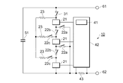
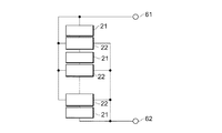
図1は本実施形態の蓄電システムの構成を表すブロック図である。図1において蓄電システム10は、第1の蓄電ユニット20とスイッチ30と制御部40と第2の蓄電ユニット50を備える。第1の蓄電ユニット20は複数の二次電池セルまたはモジュール21と、二次電池セルまたはモジュール21を直並列に切り替える複数のスイッチである第1のスイッチ22を備え、二次電池セルまたはモジュール21と第1のスイッチ22は交互に直列接続される。第1の蓄電ユニット20と第2の蓄電ユニット50とは第2のスイッチ30により切断される。第1のスイッチ22および第2のスイッチ30は制御部40により制御される。蓄電システムの入出力はプラス端子61とマイナス端子62より行われる。
FIG. 1 is a block diagram showing the configuration of the power storage system of this embodiment. In FIG. 1, the
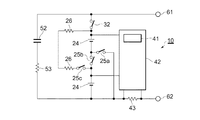
図2は図1における蓄電システム10の詳細例を示す図である。図2においては二次電池セルまたはモジュール21を3個直列に接続したものである。スイッチ22aは各二次電池21のマイナス側を接続する。スイッチ22bは各二次電池21を直列接続から切断する。スイッチ22cは各二次電池21のプラス側を接続する。蓄電ユニット50としてコンデンサ51を用いた。電流制限抵抗23はセルバランス動作時の電流値を制限する抵抗である。二次電池監視装置42は各二次電池セルまたはモジュール21の電圧を検出すると共に、電流検出抵抗43の電圧を検出し入出力電流を検出する。制御部41は二次電池監視装置42が検出した電池パラメータに基づきそれぞれのスイッチを制御する。
FIG. 2 is a diagram showing a detailed example of the
セルバランス動作を行うか否かは、二次電池監視装置42により検出された各二次電池セルまたはモジュール21の電圧差に基づいて行う。検出電圧値の最大値および最小値の差が第1の閾値以上の場合、組電池を直列接続から並列接続に切り替えてセルバランス動作を行う。その後、検出電圧値の最大値および最小値の差が第2の閾値以下の場合セルバランス動作を停止する。
Whether or not the cell balance operation is performed is determined based on the voltage difference of each secondary battery cell or
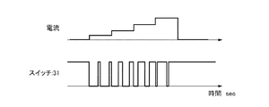
図3に図2の各スイッチのタイミングチャートを示す。二次電池セルまたはモジュール21を並列接続しセルバランスを行うには、スイッチ31をオフ後にスイッチ22bをオフ、スイッチ22aとスイッチ22cをオンする。その結果、各二次電池セルまたはモジュール21が並列接続されるため二次電池間のセルバランス動作が行われる。二次電池セルまたはモジュール21を直列に使う場合は、スイッチ22bをオン、スイッチ22aとスイッチ22cをオフ後にスイッチ31をオンする。
FIG. 3 shows a timing chart of each switch in FIG. In order to perform the cell balance by connecting the secondary battery cells or
セルバランス時の二次電池セルまたはモジュール21に流れる電流値は電流制限抵抗23の値と各二次電池セルまたはモジュール21の電圧差によって決定される。電流制限抵抗の値が小さい程、または、各二次電池セルまたはモジュール21の電圧差が大きいほど二次電池セルまたはモジュール21に流れる電流値は大きくなる。
The value of current flowing in the secondary battery cell or
蓄電システム10が充電あるいは放電中の二次電池セルまたはモジュール21のセルバランス時は、電流の入出力はコンデンサ51により行われる。そのため、セルバランス動作時間は入出力電流とコンデンサ51の容量によって制限される。二次電池セルまたはモジュール21の入出力電流が小さい場合は、コンデンサ51の電圧変動が小さいためセルバランス時間を長く確保可能であり、逆に、二次電池セルまたはモジュール21の入出力電流が大きい場合はコンデンサ51の電圧変動が大きいためセルバランス時間は短くする必要がある。
During the cell balance of the secondary battery cell or
そこで、制御部41は二次電池監視装置42が検出した入出力電流の大きさに合わせてそれぞれのスイッチのオン/オフするタイミングを決定することでセルバランス時間の最適化が可能となる。
Therefore, the
図4にスイッチ31のタイミング制御について示す。図4は入出力電流の大きさに合わせて、スイッチ31をオフするパルスの時間の関係である。スイッチ31がオフの期間にセルバランスが行われる。入出力電流が小さい場合はスイッチ31をオフしセルバランスを行う時間を長く確保し、入出力電流が大きい場合はスイッチ31をオフしセルバランスを行う時間を短くする。このように、スイッチ31を入出力電流の大きさに合わせて制御することで、入出力電流値に合わせたセルバランス動作が可能となる。
FIG. 4 shows the timing control of the
実施例について図面を参照して説明する。 Embodiments will be described with reference to the drawings.
図5に本実施例に用いた回路図を示す。リチウムイオン二次電池24の電池容量は2Ah、充電の上限電圧は4.2V、放電下限電圧は3.0Vである。並列に接続するコンデンサ52の容量は1000uFであり、直列に接続されてコンデンサの電流を制限する抵抗53は10Ωである。セルバランス電流を制限する抵抗26は1Ωである。それぞれのスイッチはリレーを用いており、そのオン/オフは制御部41によって制御される。
FIG. 5 shows a circuit diagram used in this embodiment. The battery capacity of the lithium ion
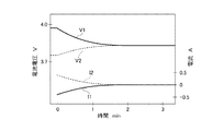
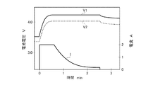
図6に本実施例において容量差のある2つのリチウムイオン二次電池24を並列に接続しセルバランスを行った時の電圧カーブと電流カーブを示す。高容量電池の電圧がV1、電流がI1であり低容量電池の電圧がV2、電流がI2である。その結果、電池間に流れる電流は電池電圧差が小さくなるにつれて小さくなり、電池電圧が一致したところで電流は流れなくなった。
FIG. 6 shows a voltage curve and a current curve when cell balancing is performed by connecting two lithium ion
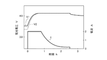
図7は本実施例において容量差のある2つのリチウムイオン二次電池24を直列に接続し、定電流定電圧充電を行った結果の充電カーブである。充電条件は設定電圧が8.4V、電流は1Cとして2Aで2時間半行った。高容量電池の電圧がV1、低容量電池の電圧がV2、充放電電流はIである。高容量電池は4.0Vで定電流定電圧充電されるが、低容量電池は4.4Vで定電流定電圧充電される。よって、低容量電池は充電時の電池電圧が充電上限電圧より高いため電池性能が劣化する。
FIG. 7 is a charging curve obtained as a result of performing constant current and constant voltage charging by connecting two lithium ion
次に、本実施例において容量差のある2つのリチウムイオン二次電池24を本蓄電システムに組み込んだ結果を示す。充電条件は上記と同様である。
Next, the result of incorporating two lithium ion
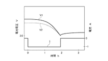
図8に、本実施例の蓄電システムにおける充電カーブを示す。セルバランス動作により二次電池電圧が高い方から低い方へ電流が流れるため、初期状態の電圧ばらつきが充電中に小さくなり最終的には2つの電池の電圧は4.2Vに一致した。よって、一方の電池のみが劣化することはない。 FIG. 8 shows a charging curve in the power storage system of this example. Since the current flows from the higher to the lower secondary battery voltage due to the cell balance operation, the voltage variation in the initial state becomes smaller during charging, and the voltages of the two batteries finally match 4.2V. Therefore, only one battery does not deteriorate.
図9に本実施例において容量差のある2つのリチウムイオン二次電池24を直列に接続し、定電流放電を行った結果の放電カーブを示す。用いたリチウムイオン二次電池24は上記と同様である。放電電流は0.5Cとして1Aである。高容量電池の電圧がV1、低容量電池の電圧がV2、充放電電流はIである。各電池の過放電電圧閾値は3.0Vである。この結果、電池の容量ばらつきにより低容量電池が先に3.0Vになったところで放電は停止した。
FIG. 9 shows a discharge curve as a result of performing constant current discharge by connecting two lithium ion
次に、本実施例において容量差のある2つのリチウムイオン二次電池24を本蓄電システムに組み込んだ結果を示す。放電条件は上記と同様である。
Next, the result of incorporating two lithium ion
図10に、本実施例の蓄電システムにおける放電カーブを示す。電池の放電を行いながら2つの電池の電圧ばらつきが小さくなり最終的には一致した。その後、各電池電圧が共に3.0Vになった時点で放電が停止した。その結果、電圧ばらつきがなくなったことで放電できる時間が増え、電池の放電容量が増加した。 In FIG. 10, the discharge curve in the electrical storage system of a present Example is shown. While the batteries were discharged, the voltage variation between the two batteries became smaller and finally matched. Thereafter, the discharge was stopped when both battery voltages reached 3.0V. As a result, since there was no voltage variation, the dischargeable time increased and the discharge capacity of the battery increased.
放電時に電流値の大きさに合わせてスイッチ32のタイミング制御した場合の効果について説明する。
The effect when the timing of the
図11は、本実施例において、スイッチ32のタイミング制御を行う前の結果であり、放電電流が変化した場合のコンデンサ52の電圧変化を示す。スイッチ32は一定の間隔でオン/オフし、スイッチ32がオフの期間にセルバランス動作が行われる。この結果、セルバランス動作中に放電電流が増加すると、コンデンサ52からの放電電流が増大し、コンデンサ電圧の低下が大きいことが分かる。
FIG. 11 shows the voltage change of the
次に、図12に、本実施例においてスイッチ32のタイミング制御を行った後の結果を示す。放電電流条件は上記と同様である。スイッチ32は放電電流の大きさに合わせてオン/オフする期間を変化させ、電流が増加するとスイッチ32がオフする期間を小さくする。その結果、コンデンサ52からの放電電流が増大しても、電圧低下が小さくできることが分かる。よって、接続される負荷への電圧変動の影響を小さくすることが可能となった。
Next, FIG. 12 shows the result after performing the timing control of the
以上のように、本発明に係る蓄電システムは、複数の二次電池を多数直列に接続した蓄電システムにおいて有用である。 As described above, the power storage system according to the present invention is useful in a power storage system in which a plurality of secondary batteries are connected in series.
10:蓄電システム
20:第1の蓄電ユニット
21:二次電池セルまたはモジュール
22:直並列切り替えスイッチ
23:電流制限抵抗
24:リチウムイオン二次電池
25:リレー
26:電流制限抵抗
30:スイッチ
31:スイッチ
32:リレー
40:制御部
41:制御部
42:電池監視装置
43:電流検出抵抗
50:第2の蓄電ユニット
51、52:コンデンサ
53:電流制限抵抗
61:プラス端子
62:マイナス端子
10: Power storage system 20: First power storage unit 21: Secondary battery cell or module 22: Series-parallel switch 23: Current limiting resistor 24: Lithium ion secondary battery 25: Relay 26: Current limiting resistor 30: Switch 31: Switch 32: Relay 40: Control unit 41: Control unit 42: Battery monitoring device 43: Current detection resistor 50: Second
Claims (3)
A current detection unit configured to detect input / output currents of the first and second power storage units; and the control unit controls the first switch and the second switch based on a detection result of the current detection unit. The electrical storage system of Claim 1 or Claim 2 provided with this.
Priority Applications (1)
| Application Number | Priority Date | Filing Date | Title |
|---|---|---|---|
| JP2013045211A JP2014176152A (en) | 2013-03-07 | 2013-03-07 | Power storage system |
Applications Claiming Priority (1)
| Application Number | Priority Date | Filing Date | Title |
|---|---|---|---|
| JP2013045211A JP2014176152A (en) | 2013-03-07 | 2013-03-07 | Power storage system |
Publications (1)
| Publication Number | Publication Date |
|---|---|
| JP2014176152A true JP2014176152A (en) | 2014-09-22 |
Family
ID=51696918
Family Applications (1)
| Application Number | Title | Priority Date | Filing Date |
|---|---|---|---|
| JP2013045211A Pending JP2014176152A (en) | 2013-03-07 | 2013-03-07 | Power storage system |
Country Status (1)
| Country | Link |
|---|---|
| JP (1) | JP2014176152A (en) |
Cited By (6)
| Publication number | Priority date | Publication date | Assignee | Title |
|---|---|---|---|---|
| JP2015133817A (en) * | 2014-01-10 | 2015-07-23 | 萩原電気株式会社 | Backup power supply device |
| JP2016086635A (en) * | 2014-10-24 | 2016-05-19 | 株式会社半導体エネルギー研究所 | Power storage device and electronic apparatus |
| CN111130163A (en) * | 2018-10-31 | 2020-05-08 | 丰田自动车株式会社 | Power supply system |
| CN112510324A (en) * | 2020-11-24 | 2021-03-16 | 安徽和鼎机电设备有限公司 | Fork truck lithium battery pack parallel topological structure and charge-discharge control method |
| US11031659B2 (en) | 2017-09-29 | 2021-06-08 | Lg Chem, Ltd. | Battery module |
| JP2021099925A (en) * | 2019-12-23 | 2021-07-01 | 工機ホールディングス株式会社 | Battery pack and electrical equipment |
Citations (5)
| Publication number | Priority date | Publication date | Assignee | Title |
|---|---|---|---|---|
| JPH10302846A (en) * | 1997-04-23 | 1998-11-13 | Shin Kobe Electric Mach Co Ltd | Battery pack and charger thereof |
| JP2009284606A (en) * | 2008-05-20 | 2009-12-03 | Honda Motor Co Ltd | Controller for capacitors |
| JP2010045923A (en) * | 2008-08-13 | 2010-02-25 | Mitsubishi Heavy Ind Ltd | Energy storage system |
| JP2010063197A (en) * | 2008-09-01 | 2010-03-18 | Toyota Industries Corp | Power supply unit and method for charging power storage means |
| JP2011072153A (en) * | 2009-09-28 | 2011-04-07 | Sanyo Electric Co Ltd | Vehicular power supply device, vehicle equipped with the same, and method for equalizing capacity of power vehicular supply device |
-
2013
- 2013-03-07 JP JP2013045211A patent/JP2014176152A/en active Pending
Patent Citations (5)
| Publication number | Priority date | Publication date | Assignee | Title |
|---|---|---|---|---|
| JPH10302846A (en) * | 1997-04-23 | 1998-11-13 | Shin Kobe Electric Mach Co Ltd | Battery pack and charger thereof |
| JP2009284606A (en) * | 2008-05-20 | 2009-12-03 | Honda Motor Co Ltd | Controller for capacitors |
| JP2010045923A (en) * | 2008-08-13 | 2010-02-25 | Mitsubishi Heavy Ind Ltd | Energy storage system |
| JP2010063197A (en) * | 2008-09-01 | 2010-03-18 | Toyota Industries Corp | Power supply unit and method for charging power storage means |
| JP2011072153A (en) * | 2009-09-28 | 2011-04-07 | Sanyo Electric Co Ltd | Vehicular power supply device, vehicle equipped with the same, and method for equalizing capacity of power vehicular supply device |
Cited By (8)
| Publication number | Priority date | Publication date | Assignee | Title |
|---|---|---|---|---|
| JP2015133817A (en) * | 2014-01-10 | 2015-07-23 | 萩原電気株式会社 | Backup power supply device |
| JP2016086635A (en) * | 2014-10-24 | 2016-05-19 | 株式会社半導体エネルギー研究所 | Power storage device and electronic apparatus |
| US11031659B2 (en) | 2017-09-29 | 2021-06-08 | Lg Chem, Ltd. | Battery module |
| CN111130163A (en) * | 2018-10-31 | 2020-05-08 | 丰田自动车株式会社 | Power supply system |
| CN111130163B (en) * | 2018-10-31 | 2023-07-28 | 丰田自动车株式会社 | Power supply system |
| JP2021099925A (en) * | 2019-12-23 | 2021-07-01 | 工機ホールディングス株式会社 | Battery pack and electrical equipment |
| CN112510324A (en) * | 2020-11-24 | 2021-03-16 | 安徽和鼎机电设备有限公司 | Fork truck lithium battery pack parallel topological structure and charge-discharge control method |
| CN112510324B (en) * | 2020-11-24 | 2022-11-08 | 安徽和鼎机电设备有限公司 | Forklift lithium battery pack parallel topology structure and charge-discharge control method |
Similar Documents
| Publication | Publication Date | Title |
|---|---|---|
| US11616375B2 (en) | Rechargeable battery systems and rechargeable battery system operational methods | |
| US10141551B2 (en) | Battery system | |
| EP2706646B1 (en) | Cell balancing system | |
| JP5858306B2 (en) | Battery pack connection control apparatus and method | |
| US9537331B2 (en) | Battery pack | |
| KR101632694B1 (en) | Battery cell voltage balancing apparatus and method | |
| US20170288417A1 (en) | Fast Charging Apparatus and Method | |
| US8476869B2 (en) | Battery voltage equalizer circuit and method for using the same | |
| US20120268057A1 (en) | Basic unit of lithium-ion battery, battery pack comprising the same, and charge/discharge equalizing method thereof | |
| US9906052B2 (en) | Power supply device | |
| CN102638081B (en) | Smart matrix battery charging-discharging managing system and managing method | |
| CN104022542A (en) | Charge/discharge control circuit and method for controlling charge/discharge | |
| CN105429212A (en) | Battery pack voltage equalization control circuit and battery management equipment | |
| JP2014176152A (en) | Power storage system | |
| KR20160099357A (en) | Battery pack and battery system including the same | |
| WO2017054148A1 (en) | Battery cell balancing structure | |
| CN102957187B (en) | Cell balance device and battery system | |
| KR20160132633A (en) | Battery system and control method for connection of the same | |
| JP2020526165A (en) | Battery management | |
| KR20180035080A (en) | Battery cell balancing circuit | |
| JP6214131B2 (en) | Battery pack charging system and battery pack charging method | |
| KR101207049B1 (en) | Charging apparatus and method for portable electronic device | |
| CN203607876U (en) | A battery equalization management apparatus | |
| JP2011045183A (en) | Charging/discharging device | |
| CN201854071U (en) | Battery pack charging management system |
Legal Events
| Date | Code | Title | Description |
|---|---|---|---|
| A621 | Written request for application examination |
Free format text: JAPANESE INTERMEDIATE CODE: A621 Effective date: 20151215 |
|
| A977 | Report on retrieval |
Free format text: JAPANESE INTERMEDIATE CODE: A971007 Effective date: 20160815 |
|
| A131 | Notification of reasons for refusal |
Free format text: JAPANESE INTERMEDIATE CODE: A131 Effective date: 20160906 |
|
| A02 | Decision of refusal |
Free format text: JAPANESE INTERMEDIATE CODE: A02 Effective date: 20170314 |