US8855446B2 - Accelerated video compression multi-tap filter and bilinear interpolator - Google Patents
Accelerated video compression multi-tap filter and bilinear interpolator Download PDFInfo
- Publication number
- US8855446B2 US8855446B2 US13/450,734 US201213450734A US8855446B2 US 8855446 B2 US8855446 B2 US 8855446B2 US 201213450734 A US201213450734 A US 201213450734A US 8855446 B2 US8855446 B2 US 8855446B2
- Authority
- US
- United States
- Prior art keywords
- pixels
- interpolated
- sub
- register
- values
- Prior art date
- Legal status (The legal status is an assumption and is not a legal conclusion. Google has not performed a legal analysis and makes no representation as to the accuracy of the status listed.)
- Expired - Fee Related, expires
Links
Images


Classifications
-
- H—ELECTRICITY
- H04—ELECTRIC COMMUNICATION TECHNIQUE
- H04N—PICTORIAL COMMUNICATION, e.g. TELEVISION
- H04N19/00—Methods or arrangements for coding, decoding, compressing or decompressing digital video signals
- H04N19/50—Methods or arrangements for coding, decoding, compressing or decompressing digital video signals using predictive coding
- H04N19/503—Methods or arrangements for coding, decoding, compressing or decompressing digital video signals using predictive coding involving temporal prediction
- H04N19/51—Motion estimation or motion compensation
- H04N19/523—Motion estimation or motion compensation with sub-pixel accuracy
-
- H—ELECTRICITY
- H04—ELECTRIC COMMUNICATION TECHNIQUE
- H04N—PICTORIAL COMMUNICATION, e.g. TELEVISION
- H04N19/00—Methods or arrangements for coding, decoding, compressing or decompressing digital video signals
- H04N19/42—Methods or arrangements for coding, decoding, compressing or decompressing digital video signals characterised by implementation details or hardware specially adapted for video compression or decompression, e.g. dedicated software implementation
- H04N19/43—Hardware specially adapted for motion estimation or compensation
-
- H—ELECTRICITY
- H04—ELECTRIC COMMUNICATION TECHNIQUE
- H04N—PICTORIAL COMMUNICATION, e.g. TELEVISION
- H04N19/00—Methods or arrangements for coding, decoding, compressing or decompressing digital video signals
- H04N19/80—Details of filtering operations specially adapted for video compression, e.g. for pixel interpolation
Definitions
- the present disclosure relates to video compression and, more particularly, to multi-tap motion compensation filters and bilinear interpolation.
- a video output from a digital video camera is generally a sequence of frames, each frame being a snapshot generated by the camera's row-column array of what is often millions of optical sensors.
- Each frame is a time sample of the impinging image and, therefore, the rate of the frames can be associated with the highest rate of motion the user desires to capture. For example, a frame rate of 15 to 30 frames per second can capture the fastest motion perceptible to the unaided human eye. Higher frame rates, for example in excess of a million frames per second, can be used for capture of high speed motion, e.g., a hummingbird's wing motion or a ballistic event.
- Motion vectors in accordance with various video-encoding standards can be generated with a sub-pixel resolution, such as half-pixel and/or quarter-pixel resolution. Since sub-pixel resolution is greater than the original image, motion vectors with sub-pixel resolution can be estimated by interpolating between original pixels, and further interpolating between interpolated pixels.
- One well-known problem associated with estimating, or interpolating sub-pixels is computational complexity. A reduction of the computational complexity associated with the estimation of motion vectors with sub-pixel resolution has been long known as desirable.
- One method in accordance with one or more exemplary embodiments can provide an interpolating of sub-pixels for a pixel array and can include forming a set of even interpolated sub-pixels, based on a window register of pixels from the pixel array and a tap coefficient register having a given tap coefficient set, updating the window register with another of the pixels, forming a set of odd interpolated sub-pixels, based on said window register and said tap coefficient register, and accumulating the even interpolated sub-pixels and the odd interpolated sub-pixels until a given termination condition is met.
- each accumulating can include updating the tap coefficient register based on another tap coefficient set and updating the window register with another of the pixels, incrementing the even interpolated sub-pixels based on the window register and the tap coefficient register, another updating the window register with another of the pixels, and incrementing the odd interpolated sub-pixels, based on the window register and the tap coefficient register.
- methods can include, upon the termination condition being met, outputting the set of even interpolated sub-pixels and the set of odd interpolated sub-pixels.
- forming the set of even interpolated sub-pixels forms the set to include four even interpolated sub-pixels, each of the four even interpolated sub-pixels having a sum of two products
- forming the set of odd interpolated sub-pixels forms the set to include four odd interpolated sub-pixels, each of the four odd interpolated sub-pixels having a sum of a corresponding two products.
- forming the set of even interpolated sub-pixels can take place during a single machine cycle and, likewise, forming the set of odd interpolated sub-pixels can take place during a single machine cycle.
- each incrementing the even interpolated sub-pixels can include incrementing each of the four even interpolated sub-pixels with a sum of another corresponding two products and, in a related aspect, each incrementing the odd interpolated sub-pixels can include incrementing each of the four odd interpolated sub-pixels with a sum of another corresponding two products.
- updating the tap coefficient register and updating the window register, combined with incrementing the even interpolated sub-pixels can take place during a single machine cycle, and in a further aspect another updating the window register combined with incrementing the odd interpolated sub-pixels can take place during a single machine cycle.
- An embodiment can include or provide an apparatus for generating interpolated pixels for a pixel array, and the aspect can include, according to various aspects, means for forming a set of even interpolated sub-pixels, based on a window of pixels from the pixel array and a given tap coefficient set, means for updating the window with another of the pixels, means for forming a set of odd interpolated sub-pixels, based on the window of pixels and said tap coefficient set, and means for accumulating the even odd interpolated sub-pixels and the odd interpolated sub-pixels until a given termination condition is met.
- the means for accumulating can be configured to update the tap coefficient set and update the window with another of the pixels, increment the even interpolated sub-pixels based on the window of pixels and the tap coefficient set, update the window of pixels with another of the pixels, and increment the odd interpolated sub-pixels, based on the window of pixels and the tap coefficient set.
- an apparatus can include means for outputting the even interpolated sub-pixels and the odd interpolated sub-pixels when the given termination condition is met.
- An embodiment can include or provide an computer-readable medium comprising instructions, which, when executed by a processor apparatus in a wireless communications system, cause the processor apparatus to perform operations carrying out a method for generating interpolated pixels for a pixel array, and in accordance with various aspects, the instructions can cause the processor apparatus to form a set of even interpolated sub-pixels, based on a window of pixels from the pixel array and a given tap coefficient set, update the window with another of the pixels, form a set of odd interpolated sub-pixels, based on the window of pixels and said tap coefficient set, and accumulate the set of even and odd interpolated sub-pixels until a given termination condition is met.
- the instruction can cause the processor apparatus to accumulate by updating the tap coefficient set and updating the window of pixels with another of the pixels, incrementing the even interpolated sub-pixels based on the window of pixels and the tap coefficient set, another updating of the window of pixels with another of the pixels, and incrementing the odd interpolated sub-pixels, based on the window of pixels and the tap coefficient set.
- the instructions can, in an aspect, cause the processor apparatus to output the even interpolated sub-pixels and the odd interpolated sub-pixels.
- An embodiment can include or provide apparatus for generating interpolated pixels for a pixel array, and the apparatus can include a logic circuit having an input for receiving pixels from a pixel array, and according to various aspects the logic circuit can be configured to form a set of even interpolated sub-pixels, based on a window of pixels from the pixel array and a given tap coefficient set, update the window with another of the pixels, form a set of odd interpolated sub-pixels, based on the window of pixels and said tap coefficient set, and accumulate the even odd interpolated sub-pixels and the odd interpolated sub-pixels until a given termination condition is met.
- the logic circuit can be configured to accumulate by updating the tap coefficient set and updating the window with another of the pixels, incrementing the even interpolated sub-pixels based on the window of pixels and the tap coefficient set, updating the window of pixels with another of the pixels, and incrementing the odd interpolated sub-pixels, based on the window of pixels and the tap coefficient set.
- the logic circuit can be configured to output the even interpolated sub-pixels and the odd interpolated sub-pixels when the given termination condition is met.
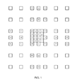
- FIG. 1 illustrates a one example arrangement of integer pixels, and interpolated fractional pixels.
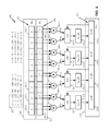
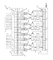
- FIG. 2 shows a functional block diagram of one example reduced cycle multi-tap interpolating filter according to one exemplary embodiment.
- FIG. 3 shows a graphical model of one example input sequence of pixels, showing a pixel window being displaced incrementally right to left along a row of image pixels, and generating corresponding interpolated half-pixels, in a processing of a reduced cycle multi-tap interpolating filter according to one or more exemplary embodiments.
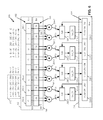
- FIG. 4 shows on the FIG. 2 functional block diagram one example machine state for a first “even” machine cycle operating on a pixel window corresponding to a FIG. 3 first pixel window position, generating starting values of a first plurality of interpolated half-pixels, in a processing of one reduced cycle multi-tap interpolating filter according to one exemplary embodiment.
- FIG. 6 shows on the FIG. 2 functional block diagram one example machine cycle, operating on a pixel window corresponding to a FIG. 3 third pixel window position, generating first accumulated or updated values of the first plurality of interpolated half-pixels, in the processing of one reduced cycle multi-tap interpolating filter according to one exemplary embodiment.
- FIG. 7 shows on the FIG. 2 functional block diagram one example next machine cycle, operating on a pixel window corresponding to a FIG. 3 fourth pixel window position, generating first accumulated or updated values of the second plurality of interpolated half-pixels, in the processing of one reduced cycle multi-tap interpolating filter according to one exemplary embodiment.
- FIG. 8 shows on the FIG. 2 functional block diagram one example final machine cycle, operating on a pixel window corresponding to a FIG. 3 fifth pixel window position, generating final values of the first plurality of interpolated half-pixels, in the processing of one reduced cycle multi-tap interpolating filter according to one exemplary embodiment.
- FIG. 9 shows on the FIG. 2 functional block diagram another example final machine cycle, operating on a pixel window corresponding to a FIG. 3 sixth pixel window position, generating final values of the second plurality of interpolated half-pixels, in the processing of one reduced cycle multi-tap interpolating filter according to one exemplary embodiment.
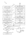
- FIG. 10 shows one example logical flow for one process of reduced machine cycle sub-pixel interpolation in one or methods and systems in accordance with various exemplary embodiments.
- FIG. 11 shows two example pixel row sections and corresponding example half-pixels generated in processes on a reduced cycle multi-tap interpolating filter according to one or more exemplary embodiments.
- FIG. 12 shows one functional block diagram of one bilinear interpolation filter, in an aspect providing interleaved chroma component, in one example implementation using one configuration of the FIG. 2 reduced cycle multi-tap interpolating filter 200 , according to one exemplary embodiment.
- accuracy of motion compensation is in units of, for example, one quarter of the distance between luma samples.
- the prediction signal consists of the corresponding samples of the reference picture.
- the corresponding sample is obtained using interpolation to generate non-integer positions.
- Prediction values at half-sample positions can be obtained by applying a one-dimensional 6-tap finite impulse response (FIR) filter horizontally and vertically.
- Prediction values at quarter-sample positions can be generated by averaging samples at integer- and half-sample positions.
- the prediction values for the chroma component can be obtained by bilinear interpolation. Since the sampling grid of chroma has lower resolution than the sampling grid of the luma, the displacements used for chroma have one-eighth sample position accuracy.
- the 8 pixel registers 202 - x forming the pixel window register 202 can be configured to be loadable in parallel, to have parallel outputs, and be configured to be selectively shifted, in unison in a bucket-brigade manner, for example in a “direction” shown as right-to-left in FIG. 2 .
- the pixel registers 202 - x can be configured such that the pixel window register 202 provides an 8-pixel, parallel-in/parallel-out shift register function.
- the pixel registers 202 - x can be S-bits wide. One example value of “S,” without limitation, is 8 bits.
- One example implementation of the pixel window register 202 can be a first-in-first-out (FIFO) or FIFO pipeline, having parallel load and output features.
- FIFO first-in-first-out
- FIFO pipeline having parallel load and output features.
- the “right-to-left” shifting of S-bit pixel data through the pixel window register 202 can provide, in part, convolving-type operations.
- One example, described in later sections in reference to FIG. 3 can effectuate a shifting of a window encompassing 8 pixels (not shown in FIG. 2 ) across a row (not shown in FIG. 2 ) of an example region of a pixel array (not shown in FIG. 2 ).
- each of the multipliers 204 can be configured with a first operand port (shown but not separately labeled) coupled, or capable of being coupled to a corresponding one of the above-described pixel registers 202 - x , and a second operand port (shown but not separately numbered) coupled to, or capable being coupled to a corresponding tap coefficient register 206 - x of the tap coefficient set register 206 .
- the tap coefficient set register 206 can include a first tap coefficient register 206 - 0 , a second tap coefficient register pair 206 - 1 and so forth ending at, for example, an eighth tap coefficient register 206 - 7 .
- the first summing device 208 - 0 , second summing device 208 - 1 , third summing device 208 - 2 and fourth summing devices 208 - 3 are also generically referenced, in an individual sense, as “a summing device 208 - y ” and collectively referenced as “summing devices 208 ,” with it being understood that labels “ 208 - y ” and “ 208 ” do not explicitly appear on the figures.
- routing or coupling logic for effecting the depicted and described couplings of the multipliers 204 to the summing devices 208 , in one aspect persons of ordinary skill in the art can, based on the present disclosure, select or otherwise implement such logic by applying conventional digital signal processor design techniques and, therefore, further detailed description of the switching, routing or coupling logic is omitted.
- the multi-tap merged interpolating filter 200 can include an accumulator 210 having, for example, four accumulator registers 210 - 0 , 210 - 1 , 210 - 2 , 210 - 3 (referenced in an individual generic sense as “accumulator register 210 - y ,” and understood that “ 210 - y ” does not explicitly appear on the figures). It will be understood that the quantity of four is only one example, and this not intended as a limitation on the scope of any embodiment.
- each summing device 208 can directly feed a corresponding accumulator register 210 - y .
- the FIG. 2 multi-tap merged interpolating filter 200 can include saturation logic, either within or in association with the summing devices 208 , such as the depicted 2S-bit signed saturation logic 212 - 0 , 212 - 1 , 212 - 2 , 212 - 3 (referenced collectively as “2S-bit signed saturation logic 212 ” and in an individual generic sense as “saturation logic” 212 - y , it being understood that the labels “ 212 ” “ 212 - y ” do not explicitly appear on the figures).
- a saturation logic 212 - y can be logically disposed between the output (shown by not separately numbered) of each summing device 208 - y and a corresponding accumulator register 210 - y .
- “logically disposed” in this and, in other instances in this description, can mean that the “2S-bit signed saturation logic” 212 - y is not necessarily a separate or dedicated hardware.
- each 2S-bit signed saturation logic 212 - y can be incorporated as a programmable feature, into logic (not separately shown) implementing the corresponding summing device 208 - y .
- multiplier 204 - 0 can multiply an 8-bit unsigned pixel data from the pixel register 202 - 0 by a corresponding signed 8-bit tap coefficient from the tap coefficient register 206 - 0 , and generate one signed 16-bit product and, similarly, multiplier 204 - 1 can multiply another 8-bit unsigned pixel data from the pixel register 202 - 1 by a corresponding signed 8-bit tap coefficient from the tap coefficient register 206 - 1 , and generate another signed 16-bit product.
- the two respective signed 16-bit products are input to two operand input ports (shown but not separately numbered) of the summing device 208 - 0 .
- remaining summing devices 208 - 1 , 208 - 2 and 208 - 3 can operate likewise on content of corresponding pixel registers 202 - x from the pixel window register 202 and content of tap coefficient registers 206 - x from the tap coefficient register 206 , and feed a respective 16-bit sum-of-products or accumulated sum-of-products result into a corresponding one of the remaining accumulator registers 210 - 1 , 210 - 2 , and 210 - 3 .
- the six step sequence can be viewed as three “even” steps interleaved with three “odd” steps. It will be understood that the labeling of “even” and “odd” is arbitrary.
- the FIG. 2 multi-tap merged interpolating filter 200 can be configured and operated through a sequence of six states or configurations, each state corresponding to one of the “even” or “odd” steps of the pixel window 302 in the sequence 302 - 0 . . . 302 - 5 .
- the formed four “even” interpolated half-pixels a, c, e, and g can be offloaded to a memory (not show).
- the offloading can provide for an interleaving of the “even” and “odd” machine cycles, with neither interfering with the other's use of the accumulator 210 .
- the interleaving feature can provide, among other benefits, a merged interpolating filter in practices according to the various exemplary embodiments.
- the pixel window register 202 in a first “odd” machine cycle can be updated to hold the pixels spanned by the pixel window 302 at the first “odd” position 302 - 1 and the pixel window register content operated upon by the tap coefficient set register 206 having, in one aspect, the same first tap coefficient set used for the first “even” machine cycle.
- This operation can, in an aspect, form initial values for the FIG. 3 example four “odd” half-pixels b, d, f and h, which can be then offloaded to memory.
- the accumulator 210 can be re-loaded with the earlier incremented four “odd” interpolated half-pixels b, d, f and h, and the pixel window register 202 updated to have the FIG. 3 pixels spanned by the pixel window 302 at the third “odd” position 302 - 5 .
- the tap can maintain the third tap coefficient set, and incrementing values can be generated to establish in the accumulator 210 final values for the four “odd” interpolated half-pixels b, d, f and h.
- a merged interpolating filter in practices according to the various exemplary embodiments by forming and accumulating four “even” interpolated half-pixels a, c, e, and g during a total of three “even” machine cycles, interleaved with forming and accumulating the four “odd” interpolated half-pixels b, d, f and h during a total of three “odd” machine cycles, can provide in just six machine cycles the full set of eight interpolated half-pixels a, b, c, d, e, f, g and h.
- the first “even” and first “odd” machine cycles can use a first tap coefficient set of [1, ⁇ 5, 1, ⁇ 5, 1, ⁇ 5, 1, ⁇ 5].
- the first tap coefficient set of [1, ⁇ 5, 1, ⁇ 5, 1, ⁇ 5, 1, ⁇ 5] is labeled as tap coefficient set register state 406 of the tap coefficient set register 206 appearing in FIGS. 4 and 5 .
- tap coefficient set register state 406 of the tap coefficient set register 206 appearing in FIGS. 4 and 5 .
- FIG. 2 Before describing example arithmetic operations shown by the FIG. 2 multi-tap merged interpolating filter 200 at its FIG. 4 through FIG. 9 machine states, it will be understood that the description assumes no latches (not shown) inserted in the various data paths, or within the various described logic and arithmetic devices.
- FIG. 2 it will be assumed that in one machine cycle pixel values from the pixel window register 202 and tap coefficient values in the tap coefficient set register 206 can pass to the multiplier array 204 , be multiplied to form respective products that pass through the summing devices 208 , through the 2S-bit saturation logic 212 and are loaded into the accumulator 210 .
- the multipliers 204 can multiply the pixel window register 202 state 402 pixels A, B, C, D, E, F, G by the tap coefficient set register 206 state 406 and generate four pair of products, and input these to respective operand ports (shown but not labeled) of a corresponding one of the summing devices 208 .
- the multiplication operations can include multiplier pair 204 - 0 , 204 - 1 receiving pixels A and B from the first and second pixel register 202 - 0 and 202 - 1 , multiplying these pixels A and B, respectively, by “1” and “ ⁇ 5” from the first tap coefficient set of [1, ⁇ 5, 1, ⁇ 5, 1, ⁇ 5, 1, ⁇ 5], then inputting the respective products, which are “A” and “ ⁇ 5B,” to the operand ports of the first summing device 208 - 0 .
- the output of the first summing device 208 - 0 , (A ⁇ 5B), thereby forms the “even” interpolated half-pixel a in the first accumulator register 210 - 0 .
- the second multiplier pair 204 - 2 , 204 - 3 can likewise receive pixels C and D from the third and fourth pixel register 202 - 2 and 202 - 3 , respectively, multiply these by “1” and “ ⁇ 5” from the third and fourth tap coefficient registers 206 - 2 and 206 - 3 at state 406 and send the resulting outputs, “C” and “ ⁇ 5D.” to the input operand ports of the second summing device 208 - 1 .
- the output of the second summing device 208 - 0 , (C ⁇ 5D), can thereby form the “even” interpolated half-pixel c in the second accumulator register 210 - 1 .
- the third multiplier pair 204 - 4 , 204 - 5 can receive pixels E and F from the fifth and sixth pixel register 202 - 4 and 202 - 5 multiply these by “1” and “ ⁇ 5” from the fifth and sixth tap coefficient registers 206 - 4 and 206 - 5 to form, through the third summing device 208 - 2 , the “even” interpolated half-pixel e in the third accumulator register 210 - 2 .
- the fourth multiplier pair 204 - 6 , 204 - 7 can receive pixels G and H from the seventh and eighth pixel register 202 - 6 and 202 - 7 multiply these by “1” and “ ⁇ 5” from the seventh and eighth tap coefficient registers 206 - 6 and 206 - 7 to form, through the fourth summing device 208 - 3 , the “even” interpolated half-pixel g in the fourth accumulator register 210 - 3 .
- the content 410 of the accumulator 210 therefore, at the end of the first “even” machine cycle in this example, can have the intermediate values of the “even” interpolated half-pixels a, c, e, g shown at region 470 of FIG. 4 .
- the content 410 having the described interpolated half-pixels a, c, e, g with values shown at region 470 can be offloaded to memory.
- FIG. 2 pixel window register 202 shifts its pixel contents one pixel to the left to encompass the pixels corresponding to the FIG. 3 second pixel window position 302 - 1 , which is B, C, D, E, F, G, H, I. This is reflected by the FIG.
- the content of the tap coefficient set register 206 remains at state 406 . i.e., the first tap coefficient set of [1, ⁇ 5, 1, ⁇ 5, 1, ⁇ 5, 1, ⁇ 5].
- multipliers 204 and summing devices 208 multiply the state 406 of the tap coefficient register 206 , i.e., the first tap coefficient set of [1, ⁇ 5, 1, ⁇ 5, 1, ⁇ 5, 1, ⁇ 5] by the pixels B, C, D, E, F, G, H in the same manner as described for the first “even” cycle, to form through the summing devices 20 the following four “odd” interpolated half-pixels b, d, f, and h in the accumulator 210 : (B ⁇ 5C) as an initial value of interpolated half-pixel b in the first accumulator register 210 - 0 ; (D ⁇ 5E) as an initial value of interpolated half-pixel d in the second accumulator register 210 - 1 ; (F ⁇ 5G) as an initial value of interpolated half-pixel f in the third accumulator register 210 - 2 ; and (H ⁇ 5I) as an initial value of interpolated half-pixel h in
- the content 510 of the accumulator 210 i.e., the initial values of the “odd” interpolated half-pixels b, d, f, and h is shown at region 572 of FIG. 5 and, in an aspect, can be offloaded to memory.
- the second “even” machine cycle can include re-loading the earlier formed four “even” interpolated half-pixels a, c, e, and g into the accumulator 210 , shifting the pixel window register 202 , e.g., by a FIFO operation, to pixel window register state 602 having pixels C, D, E, F, G, H, I, and J, and loading the tap coefficient set register 206 with the example second tap coefficient set [20, 20, 20, 20, 20, 20, 20, 20, 20] as reflected by state 606 .
- the multipliers 204 can multiply the content or state 606 of the tap coefficient set register 206 [20, 20, 20, 20, 20, 20, 20, 20] by the pixels C, D, E, F, G, H, I and J in the pixel window register 202 , and couple the resulting products to the summing devices 208 .
- the summing devices 208 by receiving these multiplier 204 outputs and the FIG. 6 depicted feedback of the earlier formed four “even” interpolated half-pixels a, c, e, and g, can form in the accumulator 210 the incremented “even” half-pixels a, c, e, and g having the following values shown at region 672 of FIG.
- incremented “even” interpolated half-pixel a equal to (A ⁇ 5B+20C+20D) in the first accumulator register 210 - 0 ; incremented “even” interpolated half-pixel c equal to (C ⁇ 5D+20E+20F) in the second accumulator register 210 - 1 ; incremented “even” interpolated half-pixel c equal to (E ⁇ 5F+20G+20H) in the third accumulator register 210 - 2 ; and incremented “even” interpolated half-pixel g equal to (G ⁇ 5H+20I+20J) in the fourth accumulator register 210 - 3 .
- these incremented four “even” interpolated half-pixels a, c, e, and g can be offloaded to memory.
- the second “odd” machine cycle can update the accumulator 210 content to the following values of the “odd” interpolated half-pixels b, d, f, and h, also shown at region 772 of FIG.
- incremented “odd” interpolated half-pixel b equal to (B ⁇ 5C+20D+20E) in the first accumulator register 210 - 0 ; incremented “odd” interpolated half-pixel d equal to (D ⁇ 5E+20F+20G) in the second accumulator register 210 - 1 ; incremented “odd” interpolated half-pixel f equal to (F ⁇ 5G+20H+20I) in the third accumulator register 210 - 2 ; and incremented “even” interpolated half-pixel h equal to (H ⁇ 5I+20J+20K) in the fourth accumulator register 210 - 3 .
- these incremented four “odd” interpolated half-pixels b, d, f, and h can be offloaded to memory.
- FIG. 2 multi-tap merged interpolating filter 200 performed a six-tap interpolating filter process in generating the above-described example sets of “even” and “odd” interpolated half-pixels.
- a 6-tap interpolating filter is only an example, and is not intended to limit the scope of practices and structures encompassed by, or that may be a practice of any embodiment.
- persons of ordinary skill in the art can readily apply concepts shown in relation to the 6-tap interpolating filter to provide an 8-tap interpolating filter.
- one example of a loading at 1004 of a tap coefficient register with a tap coefficient set can be loading or setting the tap coefficient set register 206 to state 406 with, for example, the first tap coefficient set [1, ⁇ 5, 1, ⁇ 5, 1, ⁇ 5, 1].
- the process 1000 after the 1006 forming a set of “even” sub-pixels by “even” machine cycle of an interpolating multi-tap filter in accordance with various exemplary embodiments, can go to 1008 to shift or otherwise update content of the pixel window register with pixels to corresponding to an “odd” position relative, for example, to the index associated with the “even” position at 1002 .
- position 302 - 1 shows one example of an “odd” position in accordance with 1008 .
- the process 1000 can, preferably with a pixel window register state corresponding to 1008 and a tap coefficient register associated with state 1004 , go to 1010 and form a set of “odd” sub-pixels by “odd” machine cycle of the interpolating multi-tap filter in accordance with one or more exemplary embodiments.
- a 1010 forming a set of “odd” sub-pixels by “odd” machine cycle of the interpolating multi-tap filter can be the first “odd” machine cycle described in reference to FIG. 5 forming the “odd” interpolated half-pixels b, d, f and h.
- an example operation according to the process 1000 can, after the 1010 forming the set of “odd” interpolated half-pixels b, d, f, and h, go to the terminating condition escape block 1012 to determine whether a given terminating condition for the reduced machine cycle sub-pixel interpolation is met.
- the above-described forming of the four “even” interpolated half-pixels a, c, e, and g and four “odd” interpolated half-pixels b, d, f and h can comprise the entirety of the arithmetic operations, in other words can generate the final values of the complete set of eight interpolated half-pixels a, b c, d, e, f, g and h.
- This “Option 2” aspect can provide a two machine cycle generation of a full set final interpolated half-pixels a, b c, d, e, f, g and h, each being a sum of two products.
- the first instance of the accumulating 1050 can be, at 1014 , shifting or otherwise updating content of the pixel window register (e.g., the FIG. 2 pixel window register 202 ) with pixels corresponding to another “even” position and loading or otherwise updating the tap coefficient register with another set of tap coefficients.
- position 302 - 2 illustrates one example of another “even” position in accordance with 1014 .
- FIG. 4 loading or setting FIG. 4 tap coefficient set register 206 to state 606 with, for example, the second tap coefficient set [20, 20, 20, 20, 20, 20, 20, 20] show one example of the 1014 loading or otherwise updating the tap coefficient set register with another tap coefficient set.
- FIG. 4 pixel window register 202 state 402 also reflects the above-described FIG. 3 example position 302 - 2 of an “even” position at 1014 .
- One example of a 1016 incrementing or otherwise updating the set of “even” sub-pixels by “even” machine cycle of the interpolating multi-tap filter can be the second “even” machine cycle described in reference to FIG. 6 for incrementing the “even” interpolated half-pixels a, c, e, and g.
- FIG. 10 in one example operation of the process 1000 , after the 1016 incrementing the set of “even” sub-pixels by “even” machine cycle of an interpolating multi-tap filter, can go to 1018 to shift or otherwise update content of the pixel window register with pixels to corresponding to another “odd” position relative, for example, to the index associated with the “even” positions at 1002 and 1014 .
- FIG. 3 position 302 - 3 can be an example of an “odd” position in accordance with 1018 .
- the process 1000 can, with “odd” pixel window register state corresponding to 1018 and the same tap coefficient register state used in the “even” updating at 1016 , go to 1020 and increment or otherwise update the set of “odd” sub-pixels. Assuming this to be the first instance of the incrementing or updating at 1020 the basis “odd” sub-pixels can be the set formed at 1010 .
- the basis “odd” sub-pixels will be the set previously incremented by a preceding iteration through the accumulating, i.e., through 1014 , 1016 , 1018 , 1020 , formed as a loop by the terminating condition escape block 1012 .
- One example of a 1020 incrementing or otherwise updating the set of “odd” interpolated sub-pixels by “odd” machine cycle of the interpolating multi-tap filter can be the second “odd” machine cycle described in reference to FIG. 7 for incrementing the “odd” interpolated half-pixels b, d, f and h.
- the process 1000 after the 1020 incrementing the set of “odd” sub-pixels by “odd” machine cycle of an interpolating multi-tap filter, can go to terminating condition escape block 1040 to determine if the given terminating condition, which for this aspect is a given number of times repeating the accumulating 1050 .
- terminating condition escape block 1040 One such example, described in greater detail below in reference FIGS. 8 and 9 together with FIG. 10 , is performing the example second and final incrementing of the “even” interpolated half-pixels a, c, e, and g which, in the example, is by the FIG.
- the given terminating condition is more than one repeat of the accumulating 1050 and, therefore, the answer at terminating condition escape block 1012 is “NO.”
- the process 1000 therefore returns to the accumulating 1050 .
- the loop of 1014 , 1016 , 1018 , 1020 , 1012 continues until the terminating condition at the terminating condition escape block 1012 is met.
- FIGS. 8 and 9 show one example an iteration of the accumulating 1050 loop of 1014 , 1016 , 1018 and 1020 .
- the accumulating 1050 of the sub-pixels is complete and the process 1000 can go to 1014 and output the final interpolated sub-pixels.
- one example outputting 1014 of the final interpolated sub-pixels is the described generation of the final values for the sub-pixels a, b, c, d, e, f, g and h.
- FIG. 11 shows, as one example input 1100 that can be processed in a reduced cycle multi-tap interpolating filter apparatus and filter method according to one exemplary embodiment two pixel row sections, 1102 _ 0 and 1102 _ 1 .
- Pixel row section 1102 _ 0 is shown having “whole” pixels 0A, 0B, 0C, 0D, 0E, 0F, 0G, 0H, 0I, 0J, 0K, 0L, and 0M (collectively “pixels 0A-0M”) and pixel row section pixel row 102 _ 1 is shown having “whole” pixels 1A, 1B, 1C, 1D, 1E, 1F, 1G, 1H, 1I, 1J, 1K, 1L and 1M collectively “pixels 1A-1M”).
- pixels 0A-0A and 1A-1M have given values, for example but not limited to outputs, or filtered outputs of a optical detector (not shown).
- row within the phrase “pixel row sections” does not necessarily mean pixels must be from a “row” of a row-by-column video array.
- pixel row sections 1102 _ 0 and 1102 _ 1 may be from adjacent or otherwise spaced “columns,” (not shown) of array, adjacent diagonals (not shown) or from other respective regions of an array.
- pixel row section 1102 _ 0 is also shown having half-pixel locations 0a, 0b, 0c, 0d, 0e, 0f, 0g and 0h (collectively “half-pixels 0a-0h”) and, similarly, pixel row section 1102 _ 1 is shown having half-pixel locations 1a, 1b, 1c, 1d, 1e, 1f, 1g and 1h (collectively “half-pixels 1a-1h”).
- pseudo-code Section A1 shows example computer-executable instructions for a reduced cycle multi-tap interpolating filter apparatus and filter method according to one exemplary embodiment, and its operation in generating half-pixels 0a-0h and half-pixels 1a-1h in accordance with one of more exemplary embodiments, using example pixel row 102 _ 0 pixels 0A-0M and pixel row 102 _ 1 pixels 1A-1M.
- FIG. 12 shows one bilinear interpolation of interleaved chroma component configuration 1200 of the FIG. 2 reduced cycle multi-tap interpolating filter 200 according to one exemplary embodiment.
- the interleaved chroma component configuration 1200 can multiply eight 8-bit signed bytes in the Rss register 202 by the corresponding 8-bit unsigned bytes in the Rtt register 206 , and configures the summing devices 208 - 0 , 208 - 1 , 208 - 2 , and 208 - 3 in a manner that adds the multiplication results in cross pairs as shown by the directed arrows from the multipliers 204 to the summing devices 208 . Comparing FIGS.
- FIG. 13 shows one example array 1300 of pixels that can be involved in a bilinear interpolation of a planar chroma component in accordance with one exemplary embodiment.
- FIG. 14 shows an example array 1400 of pixels having one-quarter pixels generated in a bilinear interpolation of a planar chroma component, based on the FIG. 13 example array 1300 .
- pseudo-code Section A2 shows example, referring to FIGS. 13 and 14 , of computer-executable instructions for generating one-quarter pixels in a bilinear interpolation of a planar chroma component in an apparatus and method according to one of more exemplary embodiments.
- FIG. 15 illustrates an exemplary wireless communication system 1500 in which one or more embodiments of the disclosure may be advantageously employed.
- the exemplary wireless communication system 1500 shows three remote units 1520 , 1530 , and 1550 and two base stations 1540 .
- the remote units 1520 , 1530 , and 1550 can include semiconductor devices 1525 , 1535 and 1555 , and one or more of the semiconductor devices 1525 , 1535 and 1555 can include one or more reduced cycle multi-tap interpolating filters in accordance with various exemplary embodiments, for example, without limitation, the reduced cycle multi-tap interpolating filter described in reference to FIG.
- FIG. 15 shows forward link signals 1580 from the base stations 1540 and from the remote units 1520 , 1530 , and 1550 and reverse link signals 1590 from the remote units 1520 , 1530 , and 1550 to the base stations 1540 .
- the remote unit 1520 is shown as a mobile telephone
- the remote unit 1530 is shown as a portable computer
- the remote unit 1550 is shown as a fixed location remote unit in a wireless local loop system.
- the remote units 1520 , 1530 and 1550 may be one or more of a mobile phone, hand-held personal communication systems (PCS) unit, portable data units such as a personal data assistant, navigation devices (such as GPS enabled devices), set top box, music player, video player, entertainment unit, fixed location data unit such as a meter reading equipment, or any other device that stores or retrieves data or computer instructions, or any combination thereof.
- PCS personal communication systems
- FIG. 15 illustrates remote units according to the teachings of the disclosure
- the disclosure is not limited to these exemplary illustrated units.
- Embodiments of the disclosure may be suitably employed in any device which includes at least one semiconductor die having active integrated circuitry including memory and on-chip circuitry for test and characterization.
- a software module may reside in RAM memory, flash memory, ROM memory.
- An exemplary storage medium is coupled to the processor such that the processor can read information from, and write information to, the storage medium. In the alternative, the storage medium may be integral to the processor.
- an embodiment of the invention can include a computer readable media embodying a method for phase sampling a received serial bit stream as according to methods of described embodiments. Accordingly, the invention is not limited to illustrated examples and any means for performing the functionality described herein are included in embodiments of the invention.
Landscapes
- Engineering & Computer Science (AREA)
- Multimedia (AREA)
- Signal Processing (AREA)
- Image Processing (AREA)
- Compression Or Coding Systems Of Tv Signals (AREA)
Abstract
Description
b 1=(E−5F+20G+20H−5I+J) Eq. (1)
h 1=(A−5C+20G+20M−5R+T) Eq. (2)
b=(b 1+16)>>5 Eq. (3)
h=(h 1+16)>>5 Eq. (4)
j 1 =cc−5dd+20h 1+20m 1−5ee+ff Eq. (5)
where intermediate values denoted by cc, dd, ee, m1, and ff are obtained in a manner similar to h1. The final prediction value j can then computed as
j=(j 1+512)>10 Eq. (6)
and clipped to the range of 0 to 255.
a=(G+b+1)>1 Eq. (7)
e=(b+h+1)>>1 Eq. (8)
Claims (22)
Priority Applications (5)
| Application Number | Priority Date | Filing Date | Title |
|---|---|---|---|
| US13/450,734 US8855446B2 (en) | 2012-04-19 | 2012-04-19 | Accelerated video compression multi-tap filter and bilinear interpolator |
| EP13721171.0A EP2839650A1 (en) | 2012-04-19 | 2013-04-18 | Accelerated multi-tap filter and bilinear interpolator for video compression |
| CN201380020605.0A CN104247435B (en) | 2012-04-19 | 2013-04-18 | Acceleration multi-tap wave filter and bi-linear interpolator for video compress |
| PCT/US2013/037206 WO2013158903A1 (en) | 2012-04-19 | 2013-04-18 | Accelerated multi-tap filter and bilinear interpolator for video compression |
| JP2015507184A JP6382795B2 (en) | 2012-04-19 | 2013-04-18 | Accelerated video compression multi-tap filter and bilinear interpolator |
Applications Claiming Priority (1)
| Application Number | Priority Date | Filing Date | Title |
|---|---|---|---|
| US13/450,734 US8855446B2 (en) | 2012-04-19 | 2012-04-19 | Accelerated video compression multi-tap filter and bilinear interpolator |
Publications (2)
| Publication Number | Publication Date |
|---|---|
| US20130279827A1 US20130279827A1 (en) | 2013-10-24 |
| US8855446B2 true US8855446B2 (en) | 2014-10-07 |
Family
ID=48325888
Family Applications (1)
| Application Number | Title | Priority Date | Filing Date |
|---|---|---|---|
| US13/450,734 Expired - Fee Related US8855446B2 (en) | 2012-04-19 | 2012-04-19 | Accelerated video compression multi-tap filter and bilinear interpolator |
Country Status (5)
| Country | Link |
|---|---|
| US (1) | US8855446B2 (en) |
| EP (1) | EP2839650A1 (en) |
| JP (1) | JP6382795B2 (en) |
| CN (1) | CN104247435B (en) |
| WO (1) | WO2013158903A1 (en) |
Families Citing this family (2)
| Publication number | Priority date | Publication date | Assignee | Title |
|---|---|---|---|---|
| US11409525B2 (en) * | 2018-01-24 | 2022-08-09 | Intel Corporation | Apparatus and method for vector multiply and accumulate of packed words |
| CN108322759B (en) * | 2018-02-24 | 2021-02-05 | 北京奇艺世纪科技有限公司 | Pixel value acquisition method and device and electronic equipment |
Citations (7)
| Publication number | Priority date | Publication date | Assignee | Title |
|---|---|---|---|---|
| US5500811A (en) | 1995-01-23 | 1996-03-19 | Microunity Systems Engineering, Inc. | Finite impulse response filter |
| US6061521A (en) | 1996-12-02 | 2000-05-09 | Compaq Computer Corp. | Computer having multimedia operations executable as two distinct sets of operations within a single instruction cycle |
| US6175592B1 (en) | 1997-03-12 | 2001-01-16 | Matsushita Electric Industrial Co., Ltd. | Frequency domain filtering for down conversion of a DCT encoded picture |
| US6188803B1 (en) | 1996-10-18 | 2001-02-13 | Sony Corporation | Image processing device |
| US6470370B2 (en) | 1995-09-05 | 2002-10-22 | Intel Corporation | Method and apparatus for multiplying and accumulating complex numbers in a digital filter |
| US20040139138A1 (en) | 2001-10-29 | 2004-07-15 | Yen-Kuang Chen | Method and apparatus for efficient bi-linear interpolation and motion compensation |
| EP1605704A2 (en) | 2004-05-28 | 2005-12-14 | Samsung Electronics Co., Ltd. | Image interpolation apparatus and methods |
Family Cites Families (5)
| Publication number | Priority date | Publication date | Assignee | Title |
|---|---|---|---|---|
| JPH10124656A (en) * | 1996-10-18 | 1998-05-15 | Sony Corp | Image processor and method therefor |
| JP4898103B2 (en) * | 2003-07-16 | 2012-03-14 | 三星電子株式会社 | Video encoding / decoding device and method for color video |
| CN100455025C (en) * | 2005-07-21 | 2009-01-21 | 华为技术有限公司 | Fractional pixel interpolation method and encoding and decoding apparatus |
| CN101009842B (en) * | 2006-01-11 | 2012-02-01 | 华为技术有限公司 | Method and device for value insertion in the hierarchical video compression |
| CN101938644A (en) * | 2009-07-03 | 2011-01-05 | 哈尔滨工业大学深圳研究生院 | Hardware implementation method for video compression 1/2 pixel accuracy motion estimation |
-
2012
- 2012-04-19 US US13/450,734 patent/US8855446B2/en not_active Expired - Fee Related
-
2013
- 2013-04-18 WO PCT/US2013/037206 patent/WO2013158903A1/en active Application Filing
- 2013-04-18 EP EP13721171.0A patent/EP2839650A1/en not_active Withdrawn
- 2013-04-18 JP JP2015507184A patent/JP6382795B2/en not_active Expired - Fee Related
- 2013-04-18 CN CN201380020605.0A patent/CN104247435B/en not_active Expired - Fee Related
Patent Citations (8)
| Publication number | Priority date | Publication date | Assignee | Title |
|---|---|---|---|---|
| US5500811A (en) | 1995-01-23 | 1996-03-19 | Microunity Systems Engineering, Inc. | Finite impulse response filter |
| US6470370B2 (en) | 1995-09-05 | 2002-10-22 | Intel Corporation | Method and apparatus for multiplying and accumulating complex numbers in a digital filter |
| US6188803B1 (en) | 1996-10-18 | 2001-02-13 | Sony Corporation | Image processing device |
| US6061521A (en) | 1996-12-02 | 2000-05-09 | Compaq Computer Corp. | Computer having multimedia operations executable as two distinct sets of operations within a single instruction cycle |
| US6175592B1 (en) | 1997-03-12 | 2001-01-16 | Matsushita Electric Industrial Co., Ltd. | Frequency domain filtering for down conversion of a DCT encoded picture |
| US20040139138A1 (en) | 2001-10-29 | 2004-07-15 | Yen-Kuang Chen | Method and apparatus for efficient bi-linear interpolation and motion compensation |
| US8463837B2 (en) * | 2001-10-29 | 2013-06-11 | Intel Corporation | Method and apparatus for efficient bi-linear interpolation and motion compensation |
| EP1605704A2 (en) | 2004-05-28 | 2005-12-14 | Samsung Electronics Co., Ltd. | Image interpolation apparatus and methods |
Non-Patent Citations (3)
| Title |
|---|
| International Search Report and Written Opinion-PCT/U82013/037206-ISA/EPO-Aug. 1, 2013. |
| Loinaz M.J., et al., "A 200-mW, 3.3-V, CMOS Color Camera IC Producing 352 288 24-b Video at 30 Frames/s", IEEE Journal of Solid-State Circuits, IEEE Service Center, Piscataway, NJ, USA, vol. 33, No. 12, Dec. 1, 1998, XP011060893, ISSN: 0018-9200 abstract; figures 1, 10 Sections II.E, III.A. |
| Nunez-Yanez J.L., et al., "Multi-standard reconfigurable motion estimation processor for hybrid video codecs", IET Computers and Digital Techniques., vol. 5, No. 2, Mar. 4, 2011, pp. 73-85, XP006037606, ISSN: 1751-861X, DOI: 10.1049/1ET-CDT:20090070 abstract; figures 7, 12-14; table 1 Sections 2.2, 4.2, 6. |
Also Published As
| Publication number | Publication date |
|---|---|
| WO2013158903A1 (en) | 2013-10-24 |
| EP2839650A1 (en) | 2015-02-25 |
| US20130279827A1 (en) | 2013-10-24 |
| JP2015515225A (en) | 2015-05-21 |
| JP6382795B2 (en) | 2018-08-29 |
| CN104247435B (en) | 2018-03-30 |
| CN104247435A (en) | 2014-12-24 |
Similar Documents
| Publication | Publication Date | Title |
|---|---|---|
| EP1120747A2 (en) | Motion estimator | |
| US6427157B1 (en) | Fir filter structure with time- varying coefficients and filtering method for digital data scaling | |
| KR101578052B1 (en) | Motion estimation device and Moving image encoding device having the same | |
| US8509567B2 (en) | Half pixel interpolator for video motion estimation accelerator | |
| KR101354659B1 (en) | Method and apparatus for motion compensation supporting multicodec | |
| EP1605704A2 (en) | Image interpolation apparatus and methods | |
| US6704759B2 (en) | Method and apparatus for compression/decompression and filtering of a signal | |
| US8855446B2 (en) | Accelerated video compression multi-tap filter and bilinear interpolator | |
| US20070071103A1 (en) | Apparatus for digital video format down-conversion with arbitrary conversion ratio and method therefor | |
| Mert et al. | Low complexity HEVC sub-pixel motion estimation technique and its hardware implementation | |
| JP2009015637A (en) | Computational unit and image filtering apparatus | |
| EP1919212A1 (en) | Method and apparatus for interpolating chroma signal to minimize operation overhead | |
| US7149364B2 (en) | Mean filter device and filtering method | |
| US6829302B2 (en) | Pixel calculating device | |
| US6724822B1 (en) | Efficient motion compensation apparatus for digital video format down-conversion using generalized orthogonal transformation | |
| Mert et al. | An HEVC fractional interpolation hardware using memory based constant multiplication | |
| Leon et al. | A highly parallel 4K real-time HEVC fractional motion estimation architecture for FPGA implementation | |
| Song et al. | A VLSI architecture for motion compensation interpolation in H. 264/AVC | |
| JPH06225287A (en) | Arithmetic circuit | |
| US20020163594A1 (en) | Simultaneous vertical spatial filtering and chroma conversion in video images | |
| US6809777B2 (en) | Pixel calculating device | |
| Lee et al. | Reconfigurable architecture design of motion compensation for multi-standard video coding | |
| JP2002509627A (en) | Method and apparatus for generating half-pixel SAD | |
| GB2418092A (en) | Decimating image data | |
| JP2009534760A (en) | Image scaling method and apparatus |
Legal Events
| Date | Code | Title | Description |
|---|---|---|---|
| AS | Assignment |
Owner name: QUALCOMM INCORPORATED, CALIFORNIA Free format text: ASSIGNMENT OF ASSIGNORS INTEREST;ASSIGNORS:ZHOU, BO;ZENG, MAO;DU, JUNCHEN;AND OTHERS;SIGNING DATES FROM 20120329 TO 20120410;REEL/FRAME:028073/0793 |
|
| STCF | Information on status: patent grant |
Free format text: PATENTED CASE |
|
| MAFP | Maintenance fee payment |
Free format text: PAYMENT OF MAINTENANCE FEE, 4TH YEAR, LARGE ENTITY (ORIGINAL EVENT CODE: M1551) Year of fee payment: 4 |
|
| FEPP | Fee payment procedure |
Free format text: MAINTENANCE FEE REMINDER MAILED (ORIGINAL EVENT CODE: REM.); ENTITY STATUS OF PATENT OWNER: LARGE ENTITY |
|
| LAPS | Lapse for failure to pay maintenance fees |
Free format text: PATENT EXPIRED FOR FAILURE TO PAY MAINTENANCE FEES (ORIGINAL EVENT CODE: EXP.); ENTITY STATUS OF PATENT OWNER: LARGE ENTITY |
|
| STCH | Information on status: patent discontinuation |
Free format text: PATENT EXPIRED DUE TO NONPAYMENT OF MAINTENANCE FEES UNDER 37 CFR 1.362 |
|
| FP | Lapsed due to failure to pay maintenance fee |
Effective date: 20221007 |