US8852530B2 - Automated analyzer - Google Patents
Automated analyzer Download PDFInfo
- Publication number
- US8852530B2 US8852530B2 US13/039,949 US201113039949A US8852530B2 US 8852530 B2 US8852530 B2 US 8852530B2 US 201113039949 A US201113039949 A US 201113039949A US 8852530 B2 US8852530 B2 US 8852530B2
- Authority
- US
- United States
- Prior art keywords
- probe
- sample
- liquid surface
- liquid
- step part
- Prior art date
- Legal status (The legal status is an assumption and is not a legal conclusion. Google has not performed a legal analysis and makes no representation as to the accuracy of the status listed.)
- Active, expires
Links
Images


Classifications
-
- G—PHYSICS
- G01—MEASURING; TESTING
- G01N—INVESTIGATING OR ANALYSING MATERIALS BY DETERMINING THEIR CHEMICAL OR PHYSICAL PROPERTIES
- G01N35/00—Automatic analysis not limited to methods or materials provided for in any single one of groups G01N1/00 - G01N33/00; Handling materials therefor
- G01N35/10—Devices for transferring samples or any liquids to, in, or from, the analysis apparatus, e.g. suction devices, injection devices
- G01N35/1004—Cleaning sample transfer devices
-
- G—PHYSICS
- G01—MEASURING; TESTING
- G01N—INVESTIGATING OR ANALYSING MATERIALS BY DETERMINING THEIR CHEMICAL OR PHYSICAL PROPERTIES
- G01N35/00—Automatic analysis not limited to methods or materials provided for in any single one of groups G01N1/00 - G01N33/00; Handling materials therefor
- G01N35/10—Devices for transferring samples or any liquids to, in, or from, the analysis apparatus, e.g. suction devices, injection devices
- G01N35/1009—Characterised by arrangements for controlling the aspiration or dispense of liquids
- G01N35/1011—Control of the position or alignment of the transfer device
-
- G—PHYSICS
- G01—MEASURING; TESTING
- G01N—INVESTIGATING OR ANALYSING MATERIALS BY DETERMINING THEIR CHEMICAL OR PHYSICAL PROPERTIES
- G01N35/00—Automatic analysis not limited to methods or materials provided for in any single one of groups G01N1/00 - G01N33/00; Handling materials therefor
- G01N35/10—Devices for transferring samples or any liquids to, in, or from, the analysis apparatus, e.g. suction devices, injection devices
- G01N35/1009—Characterised by arrangements for controlling the aspiration or dispense of liquids
- G01N2035/1025—Fluid level sensing
-
- Y—GENERAL TAGGING OF NEW TECHNOLOGICAL DEVELOPMENTS; GENERAL TAGGING OF CROSS-SECTIONAL TECHNOLOGIES SPANNING OVER SEVERAL SECTIONS OF THE IPC; TECHNICAL SUBJECTS COVERED BY FORMER USPC CROSS-REFERENCE ART COLLECTIONS [XRACs] AND DIGESTS
- Y10—TECHNICAL SUBJECTS COVERED BY FORMER USPC
- Y10T—TECHNICAL SUBJECTS COVERED BY FORMER US CLASSIFICATION
- Y10T436/00—Chemistry: analytical and immunological testing
- Y10T436/25—Chemistry: analytical and immunological testing including sample preparation
- Y10T436/2575—Volumetric liquid transfer
Definitions
- the embodiments of the present invention relate to an automated analyzer for samples and reagent.
- Blood is constituted from blood cell components and plasma components.
- Blood cell components include red blood cells, white blood cells, and blood platelets.
- glycohemoglobin A combination of hemoglobin in the red blood cells and blood glucose is known as glycohemoglobin. The more sugar that remains in the blood, the more glycohemoglobin is correspondingly obtained.
- glycohemoglobin is HbA1c.
- the measured value of HbA1c correlates with the mean value of the blood-sugar level for approximately the past 60 days from the time of blood collection. Based on that, it is possible to understand the blood condition of a subject for this period.
- the collected blood is placed in a container and a rotor is put in place, with the bottom of the container facing out.
- a high gravity is applied to the blood, and the blood cell parts with greater specific gravity sink to the bottom.
- the plasma components are separated as a supernatant (centrifugation). Moreover, even without centrifugation, when the collected blood is placed in a container, the blood cell parts with greater specific gravity sink to the bottom.
- a probe when dispensing a serum, a probe is shallowly inserted into a container, the serum is absorbed by a specified amount only, and the absorbed serum is dispensed into a reaction container.
- the automated analyzer in order to improve the accuracy of the dispensing, there is a probe in which the internal diameter and the outer diameter of the tip is formed so as to be as small as possible, and in which the overall length of the probe is supplemented from the tip to the upper side. Based on this, a step part is formed on the probe.
- the sample When raising the probe from the operating position to the predefined position, the sample is attached to the step part of the probe that passes through the liquid level of the sample.
- the sample that is attached to the step part spatters and contaminates the surroundings. Moreover, there are cases in which the spattered sample enters the reaction container and causes a measurement error.
- cleaning water is attached to the step part of the probe that passes through the liquid level of the cleaning solution.
- the cleaning water that is attached to the step part spatters and contaminates the surroundings. Moreover, after cleaning the outer diameter part and the internal diameter part of the probe, when performing the subsequent dispensing of the sample, the cleaning water that is attached to the step part is brought inside the container, and the sample is diluted. This causes the measurement error in the constituent amount of reaction solution.
- the nozzle 4 On the both walls of the pathway, the nozzle 4 is provided. On the road surface of the pathway, an outlet 6 is provided. Resulting from the gas 2 that is sprayed from the nozzle 4 , the cleaning water that is attached to the probe 1 is blown off. The cleaning water that is blown off turns into a droplet 7 and flows into a drainpipe 8 from the outlet 6 .
- the conventional technology that processes the sample or cleaning solution that is attached to the step part has been described above; however, regardless of the presence or absence of the step part, when pulling up a probe that is inserted deep into the sample, there are many cases in which the sample is attached to the tip part of the probe.
- the sample that is attached causes the spattering and contamination.
- the speed at which the probe is pulled up may be set low.
- raising the probe required a long time and in that the efficiency of the series of actions to dispense the sample decreased.
- FIG. 1 is an overall view of an automated analyzer according to the first embodiment.
- FIG. 2 is a conceptual view of the automated analyzer.
- FIG. 3 is a perspective view of a sample probe, a sample arm, and a sample-probe driver.
- FIG. 4A is a functional block diagram of the automated analyzer.
- FIG. 4B is a functional block diagram of a driving controller.
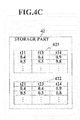
- FIG. 4C is a functional block diagram of a storage part.
- FIG. 5 is a diagram showing the action of a probe.
- FIG. 6 is a diagram showing the moving speed of the probe when ascending.
- FIG. 7A is a velocity diagram of the probe when descending.
- FIG. 7B is a velocity diagram of the probe when ascending.
- FIG. 8 is a diagram showing the moving speed of the probe when descending into a cleaning solution.
- FIG. 9 is a flow chart showing the action of the probe when descending.
- FIG. 10 is a flow chart showing the action of the probe when ascending.
- FIG. 11 is a diagram showing the moving speed of a probe of an automated analyzer according to the second embodiment when ascending.
- FIG. 12 is a velocity diagram of the probe when ascending.
- FIG. 13 is a diagram showing the moving speed of the probe of an automated analyzer according to the third embodiment when ascending.
- FIG. 14 is a velocity diagram of the probe when ascending.
- FIG. 15 is a velocity diagram of the probe according to a modified example when ascending.
- FIG. 16 is a velocity diagram of the probe according to another modified example when ascending.
- FIG. 17 is a velocity diagram of the probe of an automated analyzer according to the fourth embodiment when ascending.
- FIG. 18 is a velocity diagram of the probe according to another example when ascending.
- FIG. 19 is a velocity diagram of the probe according to another example when ascending.
- FIG. 20 is a diagram showing an conventional art that sprays gas to a probe from both sides.
- An automated analyzer includes an axial probe.
- the probe is configured to move between below the liquid surface of any liquid among a sample, reagent, and cleaning water and above the liquid surface, dispense the sample and the reagent into a reaction container, and be cleaned with the cleaning water.
- the automated analyzer analyzes components of a reaction solution generated from the dispensed sample and reagent.
- the probe includes a step part configured to be provided between a lower shaft and an upper shaft, and to be formed such that the outer diameter changes.
- the automated analyzer includes a descending controller configured to lower the probe and an ascending controller configured to raise the probe.
- the descending controller is configured to lower the probe from a predefined position that positions the step part above the position of the liquid surface of the liquid to an operating position for performing absorption of the liquid or washing with the cleaning water by positioning the step part below the position of the liquid surface.
- the ascending controller is configured to raise the probe at a high speed from the operating position until immediately before the step part reaches the position of the liquid surface, subsequently raise the probe at a low speed that is lower than the high speed until the step part passes through the position of the liquid surface, and raise the probe at a higher speed than the low speed from immediately after the step part passes through the position of the liquid surface up to the predefined position.
- an automated analyzer includes an axial probe configured to move between below the liquid surface of any liquid among a sample, reagent, and cleaning water and above the liquid surface, dispense the sample and the reagent into a reaction container, and be cleaned with the cleaning water.
- the automated analyzer analyzes components of a reaction solution generated from the dispensed sample and reagent.
- the probe includes a step part configured to be provided between a lower shaft and an upper shaft, and to be formed such that the outer diameter changes.
- the automated analyzer includes a descending controller configured to lower the probe and an ascending controller configured to raise the probe.
- the descending controller is configured to lower the probe from a predefined position that positions the step part above the position of the liquid surface of the liquid to an operating position for performing absorption of the liquid or washing with the cleaning water by positioning the step part below the position of the liquid surface.
- the ascending controller is configured to raise the probe at a high speed from the operating position until immediately before the step part reaches the position of the liquid surface, and subsequently raise the probe at a low speed that is lower than the high speed up to the predefined position.
- an automated analyzer includes an axial probe configured to move between below the liquid surface of any liquid among a sample, reagent, and cleaning water and above the liquid surface, dispense the sample and the reagent into a reaction container, and be cleaned with the cleaning water.
- the automated analyzer analyzes components of a reaction solution generated from the dispensed sample and reagent.
- the probe includes a step part configured to be provided between a lower shaft and an upper shaft, and to be formed such that the outer diameter changes.
- the automated analyzer includes a descending controller configured to lower the probe and an ascending controller configured to raise the probe.
- the descending controller is configured to lower the probe from a predefined position that positions the step part above the position of the liquid surface of the liquid to an operating position for performing absorption of the liquid or washing with the cleaning water by positioning the step part below the position of the liquid surface.
- the ascending controller is configured to raise the probe at a low speed from the operating position until the step part passes through the position of the liquid surface, and raise the probe at a higher speed than the low speed from immediately after the step part passes through the position of the liquid surface up to the predefined position.
- an automated analyzer includes an axial probe configured to move between below the liquid surface of any liquid among a sample, reagent, and cleaning water and above the liquid surface, dispense the sample and the reagent into a reaction container, and be cleaned with the cleaning water.
- the automated analyzer analyzes components of a reaction solution generated from the dispensed sample and reagent.
- the probe includes a step part configured to be provided between a lower shaft and an upper shaft, and to be formed such that the outer diameter changes.
- the automated analyzer includes a descending controller configured to lower the probe and an ascending controller configured to raise the probe.
- the descending controller is configured to lower the probe from a predefined position that positions the lower end of the probe above the position of the liquid surface of the liquid to an operating position for performing absorption of the liquid or washing with the cleaning water by positioning the step part below the position of the liquid surface.
- the ascending controller is configured to, when raising the probe from the operating position to the predefined position, with respect to the speed in the section from the operating position until immediately before the step part reaches the position of the liquid surface, and with respect to the speed in the section from immediately after the lower end of the probe passes through the position of the liquid surface up to the predefined position, reduce, at least, the speed in the section from immediately before the step part reaches the position of the liquid surface until the step part passes through the position of the liquid surface, and the speed in the section from immediately before the lower end of the probe reaches the position of the liquid surface until the lower end passes through the position of the liquid surface.
- an automated analyzer includes an axial probe configured to move between below the liquid surface of any liquid among a sample, reagent, and cleaning water and above the liquid surface, dispense the sample and the reagent into a reaction container, and be cleaned with the cleaning water.
- the automated analyzer analyzes components of a reaction solution generated from the dispensed sample and reagent.
- the automated analyzer includes a descending controller configured to lower the probe and an ascending controller configured to raise the probe.
- the descending controller is configured to lower the probe from a predefined position that positions the lower end of the probe above the position of the liquid surface of the liquid to an operating position for performing absorption of the liquid or washing with the cleaning water by positioning the lower end below the position of the liquid surface.
- the ascending controller configured to raise the probe at a high speed from the operating position until immediately before the lower end reaches the position of the liquid surface, subsequently raise the probe at a low speed that is lower than the high speed until the lower end passes through the position of the liquid surface, and raise the probe at a higher speed than the low speed from immediately after the lower end passes through the position of the liquid surface up to the predefined position.
- an automated analyzer includes an axial probe configured to move between below the liquid surface of any liquid among a sample, reagent, and cleaning water and above the liquid surface, dispense the sample and the reagent into a reaction container, and be cleaned with the cleaning water.
- the automated analyzer analyzes components of a reaction solution generated from the dispensed sample and reagent.
- the automated analyzer includes a descending controller configured to lower the probe and an ascending controller configured to raise the probe.
- the descending controller is configured to lower the probe from a predefined position that positions the lower end of the probe above the position of the liquid surface of the liquid to an operating position for performing absorption of the liquid or washing with the cleaning water by positioning the lower end below the position of the liquid surface.
- the ascending controller is configured to raise the probe at a high speed from the operating position until immediately before the lower end reaches the position of the liquid surface, and subsequently raise the probe at a low speed that is lower than the high speed up to the predefined position.
- an automated analyzer includes an axial probe configured to move between below the liquid surface of any liquid among a sample, reagent, and cleaning water and above the liquid surface, dispense the sample and the reagent into a reaction container, and be cleaned with the cleaning water.
- the automated analyzer analyzes components of a reaction solution generated from the dispensed sample and reagent.
- the automated analyzer includes a descending controller configured to lower the probe and an ascending controller configured to raise the probe.
- the descending controller is configured to lower the probe from a predefined position that positions the lower end of the probe above the position of the liquid surface of the liquid to an operating position for performing absorption of the liquid or washing with the cleaning water by positioning the lower end below the position of the liquid surface.
- the ascending controller is configured to raise the probe at a low speed from the operating position until the lower end passes through the position of the liquid surface, and raise the probe at a higher speed than the low speed from immediately after the lower end passes through the position of the liquid surface up to the predefined position.
- FIG. 1 is an overall view of an automated analyzer.
- FIG. 2 is a conceptual view of an automated analyzer.
- FIG. 3 is a perspective view of a sample probe, a sample arm, and a driving device.
- FIG. 4A is a functional block diagram of the automated analyzer.
- An automated analyzer 10 comprises a sample storage 100 , sample containers 101 that house a sample (biological sample), a sample arm 102 , a sample probe 103 , first and second reagent storage 200 , a reagent containers 201 that house a reagent, a reagent arm 202 , a reagent probe 203 , a reaction storage 300 , reaction containers 301 , a driving controller 40 , a storage part 42 , a generation part 43 , a display controller 44 , a display part 50 , a cleaning tank 701 , a pump for absorbing and discharging a sample (omitted in the figures), a solenoid valve (omitted in the figures), and an actuator for driving the solenoid valve (omitted in the figures).
- the pump has a stepping motor.
- the stepping motor changes the absorption speed and the discharge speed of a sample, etc., depending on its rotation speed. By changing the rotation speed or rotation time of the stepping motor, it is possible to change the absorption amount and discharge amount of a sample, etc.
- FIG. 4B is a functional block diagram of a driving controller 40 .
- the driving controller 40 includes a controller 41 .
- the driving controller 40 includes a sample-storage driver 104 , a sample-probe driver 105 , a reagent-storage driver 204 , a reagent-probe driver 205 , and a reaction-storage driver 304 . These driving parts operate respectively upon receiving a command from the controller 41 .
- the controller 41 controls various driving parts including the sample-storage driver 104 , the sample-probe driver 105 , the reagent-storage driver 204 , the reagent-probe driver 205 , the reaction-storage driver 304 the pump described above, the solenoid valve described above, and the actuator described above.
- the controller 41 causes the storage part 42 to store control information for controlling the various driving parts.
- the generation part 43 generates the control information that should be stored in the storage part 42 upon receiving a command from the controller 41 .
- the controller 41 reads out the control information from the storage part 42 and controls the sample-probe driver 105 , etc.
- the controller 41 comprises a descending controller that controls the descending action and an ascending controller that controls the ascending action of the sample probe 103 .
- sample storage 100 and the sample-probe driver 105 representing the various driving parts described above, are described with reference to FIG. 1 to FIG. 3 .
- the sample storage 100 comprises a sample rack 130 and the sample-storage driver 104 .
- the sample rack 130 is a disk sampler on which the plurality of sample containers 101 is mounted in a circumferential direction.
- the sample-storage driver 104 by rotating the sample rack 130 in a circumferential direction, transports the plurality of sample containers 101 sequentially to the absorption position.
- the sample probe 103 is provided on the tip part of the sample arm 102 .
- the sample probe 103 is formed in an axial shape.
- the sample probe 103 comprises a lower shaft 106 in which the outer diameter is formed so as to be small, and an upper shaft 107 in which the outer diameter is formed so as to be large. Between the lower shaft 106 and the upper shaft 107 , a step part 108 that is formed such that the size of the outer diameter changes is provided.
- the lower shaft 106 refers to the area from the bottom of the step part 108 up to the lower end 109 .
- the outer shape of the step part 108 is not limited to this, and for example, it may be taper-shaped.
- the step part 108 is coated with a fluororesin.
- the fluororesin the fluororesin with the excellent water repellency is preferable, and further, the fluororesin with a large contact angle is preferable.
- fluororesin for example, includes PTFE (polytetrafluoroethylene), FEP (fluorinated ethylene-propylene: ethylene tetrafluoride-propylene hexafluoride copolymer), and PFA (perfluoroalkoxy: ethylene tetrafluoride perfluoro propyl vinyl ether), etc.
- a stepping motor 122 rotates the sample probe 103 between the absorption position P 1 and the discharge position P 2 .
- the sample probe 103 that is rotated to the absorption position P 1 absorbs the sample from the sample containers 101 that are transported to the absorption position P 1 .
- the sample probe 103 that is rotated to the discharge position P 2 discharges the absorbed sample to the reaction containers 301 that are transported to the discharge position P 2 .
- the stepping motor 122 moves the sample probe 103 to the cleaning position and the standby position.
- the sample probe 103 is fixed perpendicular to the axial direction.
- the tail end of the sample arm 102 is fixed and supported to the upper end of a spline axis 123 that is provided perpendicular to the axial direction.
- a rotating mechanism 124 is fixed.
- a spline-side pulley 125 is provided concentrically.
- a motor-side pulley 127 is fixed to the frame of the automated analyzer 10 (omitted in the figures), and is fixed to the rotating shaft of the stepping motor 122 constituting the drive source of the rotating mechanism 124 .
- a rotating belt 128 is bridged over.
- the spline-side pulley 125 synchronizes and rotates with respect to the rotation of the motor-side pulley 127 .
- the stepping motor 122 rotates the sample probe 103 centering around the spline axis 123 between the absorption position P 1 (position of the sample container 101 ) and the discharge position P 2 (position of the reaction container 301 ).
- FIG. 4C is a functional block diagram of a storage part.
- FIG. 5 is a diagram showing the respective action of a sample probe.
- FIG. 6 is a diagram showing the moving speed of a sample probe when ascending.
- FIG. 7A is a velocity diagram of the sample probe when descending.
- FIG. 7B is a velocity diagram of the sample probe when ascending.
- FIG. 8 is a diagram showing the moving speed of the probe when descending into the cleaning solution.
- the control structure of the sample-probe driver 105 in cases in which the liquid is attached to the step part 108 of the sample probe 103 is described.
- the reagent probe 203 may be the control subject.
- the liquid including a sample, reagent, and cleaning water
- it may have the control structure of the sample-probe driver 105 or the reagent-probe driver 205 for cases in which the liquid is attached to the step part 108 and the lower end 109 .
- cases in which the liquid is attached to the step part 108 and the lower end 109 are described subsequently.
- the control structure of the sample-probe driver 105 or the reagent-probe driver 205 when the liquid is attached to the lower end 109 only when the amount of the liquid that is attached to the step part 108 is extremely small and when it does not result in a measurement error, it may have the control structure of the sample-probe driver 105 or the reagent-probe driver 205 when the liquid is attached to the lower end 109 only. Cases in which the liquid is attached to the lower end 109 only are also described subsequently.
- the controller 41 when dispensing the sample by descending and ascending the sample probe 103 , causes the storage part 42 to store the respective time required for the sample probe 103 to reach the respective position of a predefined positional, a liquid level detecting position a 2 , an operating position a 3 , a position immediately before passing through the liquid level b 1 , and a position immediately after passing through the liquid level b 2 .
- FIG. 5 and FIG. 6 The above respective positions a 1 , a 2 , a 3 , b 1 , and b 2 are shown in FIG. 5 and FIG. 6 .
- the position of the liquid level that is detected is shown as H in FIG. 5 and FIG. 6 .
- the information regarding the respective time required that is stored in the storage part 42 is shown in FIG. 4C as a part of control information 421 .
- examples of the time required are shown as t 11 and t 12 .
- FIG. 7B examples of the time required are shown as t 13 , t 14 , and t 15 .
- the display controller 44 causes the display part 50 to display the control information including the default value.
- the controller 41 upon receiving a change command resulting from an operation by an operation part 61 , causes the storage part 42 to store the changed control information, and at the same time, and causes the display controller 44 to display the changed control information.
- the controller 41 causes the generation part 43 to generate the control information, upon receiving detection signals from a liquid-surface-position detector 181 . Furthermore, the controller 41 causes the storage part 42 to store the generated control information, and at the same time, causes the display controller 44 to display the generated control information.
- the operation part 61 and the liquid-surface-position detector 181 serve as a liquid-surface-information input part 180 for inputting the control information.
- the liquid-surface-position detector 181 is, for example, a liquid level sensor of capacitance type that detects the position of the liquid level by detecting an electric change when the sample probe 103 touches the liquid surface.
- the liquid-surface-position detector 181 may be an optical type or an ultrasonic type liquid level sensor.
- the default value is the information that is previously defined and stored by associating with the patient information regarding patients who are the subjects of the measurement or by associating with measurement items.
- the position of the liquid level of the liquid refers to both the position of the detected liquid surface and the position of the previously defined liquid level.
- the controller 41 generates a driving pulse based on the control information and outputs the generated driving pulse to the stepping motor 122 of the sample-probe driver 105 .
- the stepping motor 122 rotates the sample probe 103 between the absorption position P 1 and the discharge position P 2 by rotating at a predefined speed by a predefined angle corresponding to the driving pulse.
- the lower end of the spline axis 123 is supported rotatably by a block 129 .
- a nut 121 for a ball screw 120 is fixed to the block 129 .
- a rotating shaft of a vertical-movement stepping motor 122 A that is fixed to the frame of the automated analyzer 10 is directly linked.
- the nut 121 moves vertically.
- the block 129 moves vertically. Based on that, the sample probe 103 is raised or lowered between the predefined position and the operating position.
- the controller 41 generates a driving pulse based on the control information and outputs to the vertical-movement stepping motor 122 A of the sample-probe driver 105 .
- the controller 41 provides the number of pulse per unit time (for 1 second) (hereinafter referred to as simply “pulse number”) to the vertical-movement stepping motor 122 A.
- the vertical-movement stepping motor 122 A rotates at a rotation speed that is the value that multiplies the step angle by the pulse number.
- the controller 41 increases or reduces the rotation speed of the vertical-movement stepping motor 122 A by increasing or reducing the pulse number provided to the vertical-movement stepping motor 122 A. Based on that, the sample probe 103 is raised or lowered at predefined speed.
- the controller 41 controls the action of the sample probe 103 based on the control information 421 that is stored in the storage part 42 .
- ⁇ is the amount (feed) at which the nut 121 is moved relatively to the ball screw 120 when the vertical-movement stepping motor 122 A is rotated by the step angle ( ⁇ ).
- the nut 121 is constituted so as to move in a vertical direction along with the block 129 , the spline axis 123 , the sample arm 102 , and the sample probe 103 . Therefore, the speed at which the nut 121 is moved is equivalent to the speed at which the sample probe 103 is moved in a vertical direction. Moreover, as clear from the above formula (1), the pulse number that is provided to the vertical-movement stepping motor 122 A is proportional to the speed at which the sample probe 103 is moved in a vertical direction.
- the generation part 43 can calculate the distance L, based on the amount of time required t that is calculated and the previously defined pulse number n. Based on the amount of time required t that is stored in the storage part 42 and the previously defined or previously calculated distance L, the pulse number n can be obtained. Moreover, the generation part 43 can calculate the amount of time required t, based on the previously defined pulse number n and the previously defined or previously calculated L.
- the generation part 43 generates the control information 421 according to a command from the controller 41 , based on the detected information from the liquid-surface-position detector 181 . Moreover, when lowering the sample probe 103 , the speed in the section from the predefined position to the operating position, and the speed at which the sample probe 103 is raised (the respective speed in the section from the operating position up to the position immediately before passing through, the section from the position immediately before passing through up to the position immediately after passing through, and the section from the position immediately after passing through up to the predefined position) are not constant.
- the speed in the respective section is referred to as the mean speed in the respective section.
- the mean speed in the respective section is shown in FIG. 7A and FIG. 7B .
- the controller 41 In order to absorb the blood cells that sank on the bottom of the sample container 101 , the controller 41 provides the previously defined pulse number n 1 to the vertical-movement stepping motor 122 A. Based on that, the controller 41 lowers the sample probe 103 from the predefined position to the operating position. Moreover, upon receiving an operation from the operation part 61 , the controller 41 causes the storage part 42 to store the amount of time required t 12 for the sample probe 103 from starting descending until the completion of descent (when it reaches the operating position).
- the liquid-surface-position detector 181 detects that the sample probe 103 touched the liquid surface and outputs the liquid level detection signals to the controller 41 .
- the controller 41 outputs the amount of time required t 11 for the sample probe 103 from starting descending until it receives the liquid level detection signals t 11 to the generation part 43 .
- the controller 41 completes providing the pulse number n 1 to the vertical-movement stepping motor 122 A and stops the sample probe 103 from descending.
- a phase (a 1 ) in FIG. 5 shows the blood cells that sank on the bottom of the sample container 101 and the blood plasma as the supernatant.
- a phase (a 2 ) in FIG. 5 shows the sample probe 103 when the step part 108 touches the liquid surface.
- a phase (a 3 ) in FIG. 5 shows the sample probe 103 when the step part 108 is moved below the liquid surface and reaches to operating position, in order to absorb the blood cells that sank on the bottom of the sample container 101 .
- FIG. 7A shows the amount of time required t 11 for the sample probe 103 from starting descending until the liquid level detection signal is received, and the previously defined required time t 12 for the sample probe 103 from starting descending until the completion of descent (when it reaches the operating position).
- the controller 41 After absorbing the blood cells that sank on the bottom of the sample container 101 , in order to raise the sample probe 103 from the operating position to the predefined position, the controller 41 provides the previously defined pulse number n 2 to the vertical-movement stepping motor 122 A. Based on that, the sample probe 103 is raised from the operating position to the predefined position.
- the step part 108 of the sample probe 103 passes through the liquid surface.
- the generation part 43 calculates the time required t 10 for the sample probe 103 from starting ascending until the step part 108 passes through the liquid surface.
- t 10 L 3/( n 2 ⁇ )
- L 3 is the distance expressed by (n 1 ⁇ (t 12 ⁇ t 11 ) ⁇ L 0 ).
- n 2 is the pulse number.
- the generation part 43 subtracts the previously defined time t 3 from the calculated time required t 10 , and calculates the time required t 13 for the sample probe 103 from starting ascending until immediately before the step part 108 passes through the liquid surface. Moreover, the generation part 43 calculates the time required t 14 for the sample probe 103 from starting ascending until immediately after the step part 108 passes through the liquid surface, by adding the previously defined time t 4 to the time required t 10 .
- the method for calculating the time required t 10 for the sample probe 103 from starting ascending until the step part 108 passes through the liquid surface has been described. Moreover, the method for calculating the time required t 13 for the sample probe 103 from starting ascending until immediately before the step part 108 passes through the liquid surface has been described. Furthermore, the method for calculating the time required t 14 for the sample probe 103 from starting ascending until immediately after the step part 108 passes through the liquid surface has been described. Moreover, upon receiving an operation from the operation part 61 , the controller 41 causes the storage part 42 to store the time required t 15 for the sample probe 103 from starting ascending until it completes ascending (when it reaches the predefined position).
- the controller 41 starts or completes providing the predefined pulse number to the vertical-movement stepping motor 122 A, based on the time required t 13 and t 14 that are calculated according to the above, and the required time t 15 that is previously defined.
- the controller 41 Upon receiving the time required t 15 from the start of ascent, the controller 41 completes provision of the pulse number to the vertical-movement stepping motor 122 A, and stops raising the sample probe 103 .
- the sample probe 103 is raised at the low speed v 3 between the time required t 13 and the time required t 14 , and because the step part 108 of the sample probe 103 passes through the liquid surface in this period, it is possible to cause the liquid (blood plasma) to be less likely to be attached to the step part 108 .
- the low speed v 3 can be set to be the half the high speed v 2 . Furthermore, the low speed v 3 can be set to be 50 mm/sec or less.
- the controller 41 Upon receiving the operation from the operation part 61 , the controller 41 causes the storage part 42 to store by setting the v 3 to be 50 mm/sec, and the high speed v 2 and v 4 to be 100 mm/sec.
- the controller 41 provides the pulse numbers n 2 , n 3 , and n 4 corresponding to the high speed v 2 , the low speed v 3 , and the high speed v 4 , respectively, to the vertical-movement stepping motor 122 A. Moreover, the high speed v 2 and the v 4 may not have to be equal.
- the controller 41 adjusts the low speed v 3 , and the high speed v 2 and v 4 within the previously defined range. Moreover, the controller 41 causes the storage part 42 to store the adjusted high speed v 2 , the low speed v 3 , and the high speed v 4 .
- the structure for controlling the sample-probe driver 105 when cleaning the sample probe 103 after dispensing the sample is basically the same as the structure described above regarding the cases in which the sample probe 103 is dispensed.
- the structure that is the same between both cases for example, the structure in which the controller 41 provides the pulse number to the sample-probe driver 105 and in which it raises the sample probe 103 , has been omitted, and the structure that is different between both cases is primarily described.
- the sample probe 103 When cleaning the sample probe 103 , the sample probe 103 is moved to the predefined position of the cleaning tank 701 that is filled with the cleaning water.
- the controller 41 by providing the pulse number to the vertical-movement stepping motor 122 A, based on the control information 422 including the default value, lowers the sample probe 103 to the operating position at which the step part 108 of the sample probe 103 is placed below the liquid surface of the cleaning water.
- the default value is the information that is previously defined and stored by associating with the patient information regarding patients who are the subjects of measurement or by associating with measurement items.
- FIG. 4C shows a part of the control information 422 .
- FIG. 8 shows the cleaning tank 701 that is filled with the cleaning water, and the sample probe 103 that is located at the predefined position, and the sample probe 103 that is lowered to the operating position.
- the controller 41 upon receiving the operation from the operation part 61 , causes the storage part 42 to store the control information.
- the control information includes the time required t 21 for the sample probe 103 from starting descending until it touches the liquid surface of the cleaning water. Because it is possible to calculate the position of the liquid surface based on the time required t 2 , the liquid-surface-position detector 181 for detecting the position of the liquid surface is no longer necessary.
- the control information (required time) is shown as t 2 in FIG. 4C .
- the position of the liquid surface that is previously defined is shown as H 0 in FIG. 8 .
- FIG. 9 is a flow chart showing the respective action of the probe when descending
- FIG. 10 is a flow chart showing the respective action of the probe when ascending.
- the sample-probe driver 105 upon receiving a command from the controller 41 , rotates the sample arm 102 , and moves the sample probe 103 from the standby position to the position of the sample container 101 (absorption position P 1 ). Subsequently, the sample-probe driver 105 lowers the sample probe 103 (Step S 101 ).
- the controller 41 determines whether or not the time taken for the sample probe 103 from the start of descent reached the time required t 12 (Step S 102 ).
- Step S 104 it is determined whether or not the position of the liquid surface is detected and the detection signals are output by the liquid-surface-position detector 181 (Step S 104 ). If the detection signals are not output (Step S 104 ; No), the sample probe 103 continues descending (Step S 101 ). If the detection signals are detected (Step S 104 ; Yes), the controller 41 , upon receiving the detection signals, causes the storage part 42 to store the time required t 11 that is the elapsed time from starting descending the sample probe 103 (Step S 105 ).
- Step S 102 When the elapsed time from starting lowering the sample probe 103 is equal to or more than the required time t 12 (Step S 102 ; Yes), the controller 41 completes providing the pulse number n 1 to the vertical-movement stepping motor 122 A. Based on that, the probe 103 is stopped from descending (Step S 103 ). Next, the solenoid valve that receives a command from the controller 41 operates and causes the sample probe 103 to absorb the sample inside the predefined sample container 101 . Therefore, the sample probe 103 is filled with the sample.
- the solenoid valve Upon receiving a command from the controller 41 , the solenoid valve closes.
- the controller 41 by providing the pulse number n 2 to the vertical-movement stepping motor 122 A, raises the sample probe 103 at the high speed v 2 (Step S 201 ).
- Step S 201 When the elapsed time from starting raising the sample probe 103 does not reach the required time t 13 (Step S 202 ; No), the controller 41 continues raising the sample probe 103 at the high speed v 2 (Step S 201 ).
- Step S 202 When the elapsed time from starting raising the sample probe 103 reaches the required time t 13 (Step S 202 ; Yes), the controller 41 , by providing the pulse number n 3 to the vertical-movement stepping motor 122 A, raises the sample probe 103 at the low speed v 3 (Step S 203 ). When the elapsed time from starting raising the sample probe 103 does not reach the required time t 14 (Step S 204 ; No), the controller 41 continues raising the sample probe 103 at the low speed v 3 (Step S 203 ).
- Step S 204 when the elapsed time from starting raising the sample probe 103 reaches required time t 14 (Step S 204 ; Yes), the controller 41 , by providing the pulse number n 4 to the vertical-movement stepping motor 122 A, raises the sample probe 103 at the high speed v 4 (Step S 205 ).
- the controller 41 By raising the sample probe 103 at the low speed v 3 between the time required t 13 and the time required t 14 , the liquid (blood plasma) does not become attached to the step part 108 of the sample probe 103 that passes through the position of the liquid surface.
- Step S 206 When the elapsed time from starting raising the sample probe 103 does not reach the time required t 15 (Step S 206 ; No), the controller 41 continues raising the sample probe 103 at the high speed v 4 (Step S 205 ).
- Step S 207 when the elapsed time from starting raising the sample probe 103 reaches the time required t 15 (Step S 206 ; Yes), the controller 41 , by completing the provision of the pulse number n 4 to the vertical-movement stepping motor 122 A, stops raising the sample probe 103 (Step S 207 ).
- the controller 41 by completing the provision of the pulse number n 4 to the vertical-movement stepping motor 122 A, stops raising the sample probe 103 (Step S 207 ).
- the controller 41 rotates the sample arm 102 , and moves the sample probe 103 from the position of the sample container 101 (absorption position P 1 ) to the position of the reaction container 301 (discharge position P 2 ). Subsequently, the controller 41 lowers the sample probe 103 by controlling the sample-probe driver 105 . Upon receiving a command from the controller 41 , the solenoid valve operates and discharges the sample from the sample probe 103 to the predefined reaction container 301 .
- the solenoid valve closes.
- the controller 41 raises the sample probe 103 by controlling the sample-probe driver 105 .
- the controller 41 by rotating the sample arm 102 , moves the sample probe 103 from the position of the reaction containers 301 (discharge position P 2 ) to the cleaning position.
- the controller 41 controls the vertical-movement stepping motor 122 A, based on the control information 421 ; on the other hand, when cleaning the sample probe 103 , it is different in that the controller 41 controls based on the control information 422 .
- the sample-probe driver 105 moves the sample probe 103 to the standby position.
- the structure for controlling the action of the sample probe 103 and a series of actions of the sample probe 103 have been described.
- the structure of the first and the second reagent storage 200 and the actions of the first and the second reagent storage 200 are described.
- the first and the second reagent storage 200 basically have the same structure.
- the first reagent storage 200 is primarily described below.
- the second reagent storage 200 an explanation of the same parts with the first reagent storage 200 is omitted.
- the plurality of reagent containers 201 are mounted such that they are placed in a circumferential direction.
- the reagent-storage driver 204 transports the plurality of reagent containers 201 to an absorption position P 3 sequentially by rotating the reagent containers 201 in a circumferential direction.
- the reagent that reacts selectively against specific components of the sample is housed.
- the reagent that is paired with the reagent that is housed in the reagent containers 201 of the first reagent storage 200 is housed.
- the reagent probe 203 is provided at the tip part of the reagent arm 202 .
- the reagent probe 203 is formed in an axial-shape, as is the case with the sample probe 103 , and has a lower shaft in which the outer diameter is formed so as to be small, an upper shaft in which the outer diameter is formed so as to be large, and a step part that is formed such that the size of the outer diameter changes between the lower shaft and the upper shaft.
- the reagent probe 203 absorbs the reagent from the reagent containers 201 that are transported to the absorption position P 3 and discharges the absorbed reagent to the reaction containers 301 that is transported to a discharge position P 4 .
- the reagent arm 202 rotates the reagent probe 203 between the absorption position P 3 and the discharge position P 4 so as to reciprocate.
- the plurality of reaction containers 301 are housed.
- the reaction storage 300 has a reaction line 330 and the reaction-storage driver 304 .
- the plurality of reaction containers 301 are mounted in a state in which they are placed in a circumferential direction.
- the reaction-storage driver 304 transports the plurality of reaction containers 301 to the discharge position P 4 sequentially by rotating the reaction line 330 in a circumferential direction.
- the reagent-probe driver 205 upon receiving a command from the controller 41 , rotates the reagent arm 202 and moves the reagent probe 203 from the standby position to the absorption position P 3 . Furthermore, the reagent-probe driver 205 lowers the reagent probe 203 . Upon receiving a command from the controller 41 , the solenoid valve operates and causes the reagent probe 203 to absorb the reagent from the predefined reagent container 201 .
- the solenoid valve Upon receiving a command from the controller 41 , the solenoid valve operates.
- the reagent-probe driver 205 moves the reagent probe 203 from the absorption position P 3 to the discharge position P 4 by raising the reagent probe 203 and rotating the reagent arm 202 . Subsequently, the reagent-probe driver 205 lowers the reagent probe 203 .
- the solenoid valve Upon receiving a command from the controller 41 , the solenoid valve operates and causes to discharge the sample from the reagent probe 203 to the predefined reaction container 301 .
- the solenoid valve closes.
- the reagent-probe driver 205 moves the reagent probe 203 from the discharge position P 4 to the cleaning position by raising the reagent probe 203 and rotating the reagent arm 202 .
- the reagent-probe driver 205 moves the reagent probe 203 to the standby position.
- the reaction containers 301 to which the sample and the reagent are dispensed are moved toward a photometic unit 190 by the reaction-storage driver 304 . Meanwhile, the sample and the reagent inside the reaction containers 301 are stirred with a stirring bar (omitted in the figures).
- the photometic unit 190 irradiates light on the reaction containers 301 that have been stirred, and measures the absorbance for predefined wavelength from the permeated light.
- the above embodiment shows the controller 41 that switches the ascending speed of the sample probe 103 between the low speed and the high speed, by providing the predefined pulse number to the vertical-movement stepping motor 122 A. That is, immediately before the step part of sample probe 103 passes through the position of the liquid surface, the ascending speed of the sample probe 103 is switched from the high speed to the low speed, and furthermore, immediately after the step part pass through the position of the liquid surface, the ascending speed of the sample probe 103 is switched from the low speed to the high speed.
- the switching of the ascending speed is not limited to the sample probe 103 .
- the reagent can be considered to be absorbed from the middle or the lower section inside the reagent.
- the controller 41 when the reagent probe 203 for dispensing the reagent has a step part and when dispensing the reagent by positioning this step part below the liquid surface of the reagent, the controller 41 , as is the case with the sample probe 103 , can switch the ascending speed of the reagent probe 203 between the low speed and the high speed by providing the predefined pulse number to a vertical-movement stepping motor of the reagent-probe driver 205 (omitted in the figures).
- the ascending speed of the reagent probe 203 may be switched from the high speed to the low speed, and furthermore, immediately after the step part passes through the position of the liquid surface, the ascending speed of the reagent probe 203 may be switched from the low speed to the high speed.
- the controller 41 upon receiving the detection signals from the liquid-surface-position detector 181 , caused the storage part 42 to store the time required from starting descending the sample probe 103 until it reaches the liquid surface of the liquid; however, the controller 41 may be configured to cause storage part 42 to store the time required, upon receiving an input of the time required by an operation from the operation part 61 .
- the ascending period of the probe from immediately before the step part passes through the position of the liquid surface until the step part passes through the position of the liquid surface is defined to be the low speed period, and other period is defined to be the high speed period; however, they are not limited to these.
- from immediately before the step part passes through the position of the liquid surface up to the predefined position may be defined to be the low speed period and other period may be defined to be the high speed period.
- from the operating position until the step part that has started ascending passes through the position of the liquid surface may be defined to be the low speed period, and other period may be defined to be the high speed period.
- control information for controlling the sample-probe driver 105 and the reagent-probe driver 205 is the control information that is obtained by detection of the position of the liquid surface, or the control information that is previously defined by an input from the operation part 61 ; however, the sample-probe driver 105 and the reagent-probe driver 205 may be controlled by the predefined default value.
- the controller 41 controls the sample-probe driver 105 so as to raise the sample probe 103 at low speed in the section from immediately before the step part 108 of the sample probe 103 passes through the liquid surface until immediately after it passes through, such that the liquid is not attached to the step part 108 .
- the sample-probe driver 105 upon receiving a control from the controller 41 , in at least specific sections for the comparison section, may raise the sample probe 103 at the low speed.
- the comparison section includes the section from the operating position of the sample probe 103 (shown in a phase (a 3 ) in FIG. 11 ) until immediately before the step part 108 reaches the position of the liquid surface (shown in a phase (b 1 ) in FIG. 11 ), and the section from immediately after the lower end 109 of the sample probe 103 passes through the position of the liquid surface (shown in a phase (b 4 ) in FIG. 11 ) to the predefined position (shown in a phase (a 1 ) in FIG. 11 ).
- the specific sections include the section from immediately before the step part 108 reaches the position of the liquid surface (shown in a phase (b 1 ) in FIG. 11 ) until the step part 108 passes through the position of the liquid surface (shown in a phase (b 2 ) in FIG. 11 ), and the section from immediately before the lower end 109 of the sample probe 103 reaches the position of the liquid surface (shown in a phase (b 3 ) in FIG. 11 ) until the lower end 109 passes through the position of the liquid surface (shown in a phase (b 4 ) in FIG. 11 ).
- FIG. 11 is a diagram showing the moving speed of the sample probe 103 when ascending.
- FIG. 12 is a velocity diagram of the probe when ascending.
- the structure for controlling the sample-probe driver 105 such that the liquid is not attached to the step part 108 and the lower end 109 of the sample probe 103 is described.
- the second embodiment it is switched from the low speed to the high speed immediately after the lower end 109 passed through the liquid surface (shown in a phase (b 4 ) in FIG. 11 and in FIG. 12 as t 17 ). Therefore, in the section from immediately before the step part 108 of the sample probe 103 passes through the liquid surface (shown in a phase (b 1 ) in FIG. 11 and in FIG.
- the sample-probe driver 105 is controlled so as to raise the sample probe 103 at the low speed.
- FIG. 13 is a diagram showing the moving speed of the probe when ascending.
- FIG. 14 is a velocity diagram of the probe when ascending.
- FIG. 15 is a velocity diagram of the probe according to a modified example when ascending.
- FIG. 16 is a velocity diagram of the probe according to another modified example when ascending.
- the structure for controlling the sample-probe driver 105 such that the liquid is not attached to the step part 108 and the lower end 109 of the sample probe 103 is also described.
- the sample-probe driver 105 receives a control from the controller 41 , for the section from immediately before the step part 108 of the sample probe 103 passed through the liquid surface until immediately after the lower end 109 of the sample probe 103 passed through the liquid surface, the sample probe 103 is raised at the low speed.
- the sample probe 103 is slowed down.
- the section from immediately after the step part 108 of the sample probe 103 passes through the liquid surface (shown in a phase (b 2 ) in FIG. 13 and in FIG. 14 as t 14 ) until immediately before the lower end 109 of the sample probe 103 passes through the liquid surface (shown in a phase (b 3 ) in FIG. 13 and in FIG. 14 as t 16 ) is set.
- FIG. 14 shows the deceleration ⁇ in the deceleration section from the t 14 to t 16 .
- the operation efficiency of the sample probe 103 may decrease.
- the sample-probe driver 105 is controlled so as to raise the sample probe 103 at the high speed.
- a third section in which the sample probe 103 is raised at the high speed is provided between a first section and a second section below.
- the first section is a section from immediately before the step part 108 reaches the position of the liquid surface until the step part 108 passes through the position of the liquid surface (shown in FIGS. 15 as t 13 -t 14 ).
- the second section is a section from immediately before the lower end 109 of the sample probe 103 reaches the position of the liquid surface until the lower end 109 passes through the position of the liquid surface (shown in FIG. 15 as t 16 ⁇ t 17 ).
- the third section is a section in which the moving speed is at 80 (mm/s) (shown in FIG. 15 as t 14 -t 16 ).
- this high speed may be the speed exceeding the low speed (for example, 50 (mm/s) (the speed v 3 shown in FIG. 15 ), and for example, it may exceed 100 (mm/s) (the speed v 2 and v 4 shown in FIG. 15 ).
- FIG. 16 shows examples of the acceleration ⁇ 1 in the acceleration section and the deceleration ⁇ 2 in the deceleration section.
- the sample-probe driver 105 when the amount of the liquid that is attached to the step part 108 is extremely small and when it does not cause measurement error, it may control the sample-probe driver 105 such that the liquid is not attached only to the lower end 109 of the sample probe 103 . In order not to cause the liquid to be attached to the step part 108 of the sample probe 103 , it may not have to control the sample-probe driver 105 so as to raise the sample probe 103 at the low speed.
- the automated analyzer according to the fourth embodiment has a structure so as to control the sample-probe driver 105 such that the liquid is not attached only to the lower end 109 of the sample probe 103 .
- the structure so as to control the sample-probe driver 105 according to the fourth embodiment is basically the same as the structure so as to control the sample-probe driver 105 such that the liquid is not attached to the step part 108 of the sample probe 103 in the first embodiment. As a difference, the timing for switching the ascending speed of the sample probe 103 is different.
- the ascending speed of the sample probe 103 is switched at the timing shown in FIG. 7B .
- the ascending speed is switched at the timing shown in FIG. 17 . That is, from the operating position until immediately before the lower end 109 reaches the position of the liquid surface (shown in FIG. 17 as t 16 ), the sample probe 103 is raised at the high speed v 2 . Subsequently, the sample probe 103 is raised at the lower speed v 3 than the high speed v 2 until the lower end 109 passes through the position of the liquid surface (shown in FIG. 17 as t 17 ).
- the sample probe 103 is raised at the higher speed v 4 than the lower speed v 3 from immediately after the lower end 109 passes through the position of the liquid surface (shown in FIG. 17 as t 17 ) up to the predefined position (shown in FIG. 17 as t 15 ).
- the sample probe 103 is raised at the high speed v 2 from the operating position until immediately before the lower end 109 reaches the position of the liquid surface (shown in FIG. 18 as t 16 ). Subsequently, the sample probe 103 is raised at the lower speed v 3 than the high speed v 2 up to the predefined position (shown in FIG. 18 as t 15 ).
- the sample probe 103 is raised at the lower speed v 3 than the high speed v 4 from the operating position until the lower end 109 passes through the position of the liquid surface (shown in FIG. 19 as t 17 ). From immediately after the lower end 109 passes through the position of the liquid surface (shown in FIG. 19 as t 17 ) up to the predefined position (shown in FIG. 19 as t 15 ), the sample probe 103 is raised at the higher speed v 4 than the low speed v 3 .
- the control subject may be the reagent probe 203 .
- the ascending speed of the reagent probe 203 may be switched.
- the automated analyzer without reducing the efficiency of a series of actions of the automatic analysis, it is possible to cause the liquid to be less likely to be attached to the step part, by raising the probe at a low speed when the step part passes through the position of the liquid surface, based on the position of the liquid surface.
- the automated analyzer in another embodiment, it is possible to cause the liquid to be less likely to be attached to the step part by raising the probe at a low speed from immediately before the step part passes through the position of the liquid surface up to the predefined position so as not to substantially reduce the efficiency of a series of actions of the automatic analysis.
- the liquid is possible to cause the liquid to be less likely to be attached to the step part by raising the probe at a low speed from the operating position until the step part passes through the position of the liquid surface so as not to substantially reduce the efficiency of a series of actions of the automatic analysis.
- the liquid is possible to cause the liquid to be less likely to be attached to the step part and the lower end by raising the probe at a low speed so as not to substantially reduce the efficiency of a series of actions of the automatic analysis, with respect to at least the section in which the step part passes through the position of the liquid surface, and the section in which the lower end of the probe passes through the position of the liquid surface.
- the automated analyzer in another embodiment, without reducing the efficiency of a series of actions of the automatic analysis, it is possible to cause the liquid to be less likely to be attached to the lower end, by raising the probe at a low speed, based on the position of the liquid surface, when the lower end passes through the position of the liquid surface.
- the liquid is possible to cause the liquid to be less likely to be attached to the lower end by raising the probe at a low speed from immediately before the lower end passes through the position of the liquid surface up to the predefined position so as not to substantially reduce the efficiency of a series of actions of the automatic analysis.
- the liquid is possible to cause the liquid to be less likely to be attached to the lower end by raising the probe at a low speed from the operating position until the lower end of the probe passes through the position of the liquid surface so as not to substantially reduce the efficiency of a series of actions of the automatic analysis.
Landscapes
- Physics & Mathematics (AREA)
- Health & Medical Sciences (AREA)
- Life Sciences & Earth Sciences (AREA)
- Chemical & Material Sciences (AREA)
- Analytical Chemistry (AREA)
- Biochemistry (AREA)
- General Health & Medical Sciences (AREA)
- General Physics & Mathematics (AREA)
- Immunology (AREA)
- Pathology (AREA)
- Automatic Analysis And Handling Materials Therefor (AREA)
- Sampling And Sample Adjustment (AREA)
Abstract
Description
v=γ·θ·n (1)
n=L/(γ·θ·t) (2)
t10=L3/(n2·γ·θ)
Claims (3)
Applications Claiming Priority (2)
| Application Number | Priority Date | Filing Date | Title |
|---|---|---|---|
| JP2010-049222 | 2010-03-05 | ||
| JP2010049222A JP5570848B2 (en) | 2010-03-05 | 2010-03-05 | Automatic analyzer |
Publications (2)
| Publication Number | Publication Date |
|---|---|
| US20110223061A1 US20110223061A1 (en) | 2011-09-15 |
| US8852530B2 true US8852530B2 (en) | 2014-10-07 |
Family
ID=44012494
Family Applications (1)
| Application Number | Title | Priority Date | Filing Date |
|---|---|---|---|
| US13/039,949 Active 2031-03-29 US8852530B2 (en) | 2010-03-05 | 2011-03-03 | Automated analyzer |
Country Status (4)
| Country | Link |
|---|---|
| US (1) | US8852530B2 (en) |
| EP (1) | EP2363715B1 (en) |
| JP (1) | JP5570848B2 (en) |
| CN (1) | CN102192997B (en) |
Cited By (4)
| Publication number | Priority date | Publication date | Assignee | Title |
|---|---|---|---|---|
| US20120222773A1 (en) * | 2011-03-02 | 2012-09-06 | Takashi Yamato | Analyzer and position confirming method |
| US20150268230A1 (en) * | 2014-03-24 | 2015-09-24 | Sysmex Corporation | Analyzer, and method of detection liquid level in an analyzer |
| US9804184B2 (en) | 2014-11-18 | 2017-10-31 | Jeol Ltd. | Automated analyzer and method for lifting and lowering rod-like member in automated analyzer |
| US9835640B2 (en) | 2015-02-13 | 2017-12-05 | Abbott Laboratories | Automated storage modules for diagnostic analyzer liquids and related systems and methods |
Families Citing this family (14)
| Publication number | Priority date | Publication date | Assignee | Title |
|---|---|---|---|---|
| JP5752545B2 (en) * | 2011-09-22 | 2015-07-22 | 株式会社日立ハイテクノロジーズ | Automatic analyzer |
| JP6157952B2 (en) * | 2013-06-27 | 2017-07-05 | 東芝メディカルシステムズ株式会社 | Automatic analyzer |
| CN103954787A (en) * | 2014-05-08 | 2014-07-30 | 深圳市新产业生物医学工程股份有限公司 | Sample loading device and full-automatic chemiluminescence immunoassay equipment |
| JP2015224942A (en) * | 2014-05-27 | 2015-12-14 | 株式会社東芝 | Clinical laboratory equipment |
| US9797917B2 (en) * | 2014-07-11 | 2017-10-24 | Intellicyt | Contact sensing probe and methods of use for microplate liquid sampling |
| JP6681899B2 (en) * | 2015-07-29 | 2020-04-15 | 株式会社日立ハイテク | Automatic analyzer |
| EP3501654B1 (en) * | 2017-12-22 | 2021-08-25 | Tecan Trading Ag | Pipetting apparatus with a pipette tube and method for detecting a liquid within an intermediate section of pipette tube |
| JP7177596B2 (en) * | 2018-02-27 | 2022-11-24 | シスメックス株式会社 | Specimen measuring device and specimen measuring method |
| JP6876650B2 (en) * | 2018-03-30 | 2021-05-26 | 日本電子株式会社 | Automatic analyzer and automatic analysis method |
| JP6837086B2 (en) * | 2019-01-24 | 2021-03-03 | 日本電子株式会社 | Automatic analyzer |
| JP6748261B2 (en) * | 2019-05-20 | 2020-08-26 | キヤノンメディカルシステムズ株式会社 | Clinical testing equipment |
| JP7292195B2 (en) * | 2019-12-06 | 2023-06-16 | 株式会社日立ハイテク | automatic analyzer |
| WO2021157149A1 (en) * | 2020-02-07 | 2021-08-12 | 株式会社日立ハイテク | Automatic analysis system, control device, and cleaning method |
| JP2023146898A (en) * | 2022-03-29 | 2023-10-12 | キヤノンメディカルシステムズ株式会社 | Stirrer and automatic analyzer |
Citations (11)
| Publication number | Priority date | Publication date | Assignee | Title |
|---|---|---|---|---|
| JPH0277652A (en) | 1988-09-14 | 1990-03-16 | Hitachi Ltd | Dispensing device |
| JPH06249862A (en) | 1993-03-01 | 1994-09-09 | Daikin Ind Ltd | Detection of anomaly of dispensing device and device therefor |
| JP2000171470A (en) | 1998-12-07 | 2000-06-23 | Hitachi Ltd | Automatic analyzer |
| JP2000221201A (en) | 1999-02-03 | 2000-08-11 | Toshiba Corp | Automatic analyzer |
| JP2000266765A (en) | 1999-03-18 | 2000-09-29 | Hitachi Ltd | Automatic analyzer |
| JP2003344426A (en) | 2002-05-22 | 2003-12-03 | Aloka Co Ltd | Dispensation device |
| US20050255005A1 (en) * | 2004-05-13 | 2005-11-17 | Arta Motadel | Stackable pipette tips having increased accuracy |
| JP2007132855A (en) | 2005-11-11 | 2007-05-31 | Aloka Co Ltd | Liquid stirring method and liquid stirring device |
| CN101310188A (en) | 2006-01-27 | 2008-11-19 | 株式会社东芝 | Automatic analysis device and probe lifting method |
| JP2009042067A (en) | 2007-08-09 | 2009-02-26 | Hitachi High-Technologies Corp | Automatic analyzer |
| JP2009180605A (en) * | 2008-01-30 | 2009-08-13 | Olympus Corp | Dispensing device |
Family Cites Families (16)
| Publication number | Priority date | Publication date | Assignee | Title |
|---|---|---|---|---|
| US4276260A (en) * | 1980-01-28 | 1981-06-30 | Coulter Electronics, Inc. | Fluid transfer mechanism |
| JP2886894B2 (en) * | 1989-07-24 | 1999-04-26 | 株式会社日立製作所 | Automatic analyzer |
| JP3007394B2 (en) * | 1990-08-20 | 2000-02-07 | 株式会社大日本精機 | Device for injecting test liquid into test container |
| JPH07174766A (en) * | 1993-12-21 | 1995-07-14 | Toshiba Corp | Sample sampling device in automatic chemical analyzer |
| JP3295014B2 (en) * | 1997-03-19 | 2002-06-24 | 株式会社大日本精機 | Automatic extraction device for component substances in liquid samples and automatic concentration measurement device for component substances in liquid samples |
| JP3410306B2 (en) * | 1996-10-21 | 2003-05-26 | アロカ株式会社 | Sample suction method and sample suction control device |
| JP2001228162A (en) * | 2000-02-18 | 2001-08-24 | Olympus Optical Co Ltd | Liquid ejecting device, liquid ejecting head, and ejecting method |
| JP4175916B2 (en) * | 2003-02-21 | 2008-11-05 | 株式会社東芝 | Automatic analyzer |
| JP2004251796A (en) * | 2003-02-21 | 2004-09-09 | Toshiba Corp | Automatic analyzer and sample aspirating method used therein |
| JP2005249535A (en) * | 2004-03-03 | 2005-09-15 | Olympus Corp | Dispensation probe and autoanalyzer equipped therewith |
| JP2007316011A (en) * | 2006-05-29 | 2007-12-06 | Olympus Corp | Dispensing device and analyzer |
| JP4955330B2 (en) * | 2006-07-14 | 2012-06-20 | 日立アロカメディカル株式会社 | Nozzle tip for dispensing equipment |
| JP4538477B2 (en) * | 2007-08-31 | 2010-09-08 | 株式会社日立ハイテクノロジーズ | Automatic analyzer |
| JP4538478B2 (en) * | 2007-08-31 | 2010-09-08 | 株式会社日立ハイテクノロジーズ | Automatic analyzer |
| JP2009162536A (en) * | 2007-12-28 | 2009-07-23 | Yaskawa Electric Corp | Liquid sample dispensing apparatus and driving method |
| JP5222784B2 (en) * | 2009-05-22 | 2013-06-26 | 株式会社日立ハイテクノロジーズ | Liquid sampling method and automatic analyzer |
-
2010
- 2010-03-05 JP JP2010049222A patent/JP5570848B2/en active Active
-
2011
- 2011-03-03 EP EP11250248.9A patent/EP2363715B1/en active Active
- 2011-03-03 US US13/039,949 patent/US8852530B2/en active Active
- 2011-03-04 CN CN201110053298.9A patent/CN102192997B/en active Active
Patent Citations (11)
| Publication number | Priority date | Publication date | Assignee | Title |
|---|---|---|---|---|
| JPH0277652A (en) | 1988-09-14 | 1990-03-16 | Hitachi Ltd | Dispensing device |
| JPH06249862A (en) | 1993-03-01 | 1994-09-09 | Daikin Ind Ltd | Detection of anomaly of dispensing device and device therefor |
| JP2000171470A (en) | 1998-12-07 | 2000-06-23 | Hitachi Ltd | Automatic analyzer |
| JP2000221201A (en) | 1999-02-03 | 2000-08-11 | Toshiba Corp | Automatic analyzer |
| JP2000266765A (en) | 1999-03-18 | 2000-09-29 | Hitachi Ltd | Automatic analyzer |
| JP2003344426A (en) | 2002-05-22 | 2003-12-03 | Aloka Co Ltd | Dispensation device |
| US20050255005A1 (en) * | 2004-05-13 | 2005-11-17 | Arta Motadel | Stackable pipette tips having increased accuracy |
| JP2007132855A (en) | 2005-11-11 | 2007-05-31 | Aloka Co Ltd | Liquid stirring method and liquid stirring device |
| CN101310188A (en) | 2006-01-27 | 2008-11-19 | 株式会社东芝 | Automatic analysis device and probe lifting method |
| JP2009042067A (en) | 2007-08-09 | 2009-02-26 | Hitachi High-Technologies Corp | Automatic analyzer |
| JP2009180605A (en) * | 2008-01-30 | 2009-08-13 | Olympus Corp | Dispensing device |
Non-Patent Citations (2)
| Title |
|---|
| Chinese Office Action issued Dec. 3, 2012, in Chinese Patent Application No. 201110053298.9. |
| Japanese Office Action issued on Aug. 13, 2013, in Japanese Patent Application No. 2010-049222 filed Mar. 5, 2010 (in Japanese language). |
Cited By (6)
| Publication number | Priority date | Publication date | Assignee | Title |
|---|---|---|---|---|
| US20120222773A1 (en) * | 2011-03-02 | 2012-09-06 | Takashi Yamato | Analyzer and position confirming method |
| US20150268230A1 (en) * | 2014-03-24 | 2015-09-24 | Sysmex Corporation | Analyzer, and method of detection liquid level in an analyzer |
| US9733115B2 (en) * | 2014-03-24 | 2017-08-15 | Sysmex Corporation | Analyzer, and method of detection liquid level in an analyzer |
| US9804184B2 (en) | 2014-11-18 | 2017-10-31 | Jeol Ltd. | Automated analyzer and method for lifting and lowering rod-like member in automated analyzer |
| US9835640B2 (en) | 2015-02-13 | 2017-12-05 | Abbott Laboratories | Automated storage modules for diagnostic analyzer liquids and related systems and methods |
| US10775399B2 (en) | 2015-02-13 | 2020-09-15 | Abbott Laboratories | Automated storage modules for diagnostic analyzer liquids and related systems and methods |
Also Published As
| Publication number | Publication date |
|---|---|
| US20110223061A1 (en) | 2011-09-15 |
| JP2011185645A (en) | 2011-09-22 |
| EP2363715A2 (en) | 2011-09-07 |
| EP2363715B1 (en) | 2021-01-06 |
| CN102192997A (en) | 2011-09-21 |
| EP2363715A3 (en) | 2017-03-01 |
| JP5570848B2 (en) | 2014-08-13 |
| CN102192997B (en) | 2014-10-01 |
Similar Documents
| Publication | Publication Date | Title |
|---|---|---|
| US8852530B2 (en) | Automated analyzer | |
| EP2157435B1 (en) | Nozzle cleaning method, nozzle cleaning device, and automatic analyzer | |
| JP6647288B2 (en) | Automatic analyzer and method | |
| JP6517565B2 (en) | Dispensing nozzle cleaning method and automatic analyzer | |
| JP6649088B2 (en) | Automatic analyzer | |
| JP5309142B2 (en) | Automatic analyzer | |
| JP6373879B2 (en) | Automatic analyzer | |
| JP2009042067A (en) | Automatic analyzer | |
| JP2009222593A (en) | Nozzle-cleaning method and nozzle-cleaning apparatus | |
| WO2014112591A1 (en) | Automatic analysis device | |
| WO2012105398A1 (en) | Automatic analyzing device | |
| EP4071484B1 (en) | Automated analyzer | |
| JP7305891B2 (en) | automatic analyzer | |
| WO2014042079A1 (en) | Automatic analysis device | |
| WO2018055929A1 (en) | Automatic analysis device | |
| US20230009785A1 (en) | Automatic Analysis Device | |
| JP5111328B2 (en) | Automatic analyzer | |
| JP5259550B2 (en) | Automatic analyzer and sample dispensing method | |
| US12332103B2 (en) | Dispensing device, automated analysis device, and dispensing method | |
| JP2009014356A (en) | Analyzer | |
| JP4361002B2 (en) | Nozzle cleaning apparatus and biochemical analysis apparatus including the same | |
| JP2014112040A (en) | Plug opening device, sample processor and plug opening method of container | |
| WO2022255042A1 (en) | Automatic analysis device | |
| JP2011232312A (en) | Autoanalyzer | |
| JPH05164764A (en) | Sampling system for automatic chemical analysis device |
Legal Events
| Date | Code | Title | Description |
|---|---|---|---|
| AS | Assignment |
Owner name: TOSHIBA MEDICAL SYSTEMS CORPORATION, JAPAN Free format text: ASSIGNMENT OF ASSIGNORS INTEREST;ASSIGNORS:OONUMA, TAKEHIKO;SUGIMURA, TOMOHIRO;REEL/FRAME:025897/0274 Effective date: 20110131 Owner name: KABUSHIKI KAISHA TOSHIBA, JAPAN Free format text: ASSIGNMENT OF ASSIGNORS INTEREST;ASSIGNORS:OONUMA, TAKEHIKO;SUGIMURA, TOMOHIRO;REEL/FRAME:025897/0274 Effective date: 20110131 |
|
| STCF | Information on status: patent grant |
Free format text: PATENTED CASE |
|
| FEPP | Fee payment procedure |
Free format text: PAYOR NUMBER ASSIGNED (ORIGINAL EVENT CODE: ASPN); ENTITY STATUS OF PATENT OWNER: LARGE ENTITY |
|
| AS | Assignment |
Owner name: TOSHIBA MEDICAL SYSTEMS CORPORATION, JAPAN Free format text: ASSIGNMENT OF ASSIGNORS INTEREST;ASSIGNOR:KABUSHIKI KAISHA TOSHIBA;REEL/FRAME:038891/0693 Effective date: 20160316 |
|
| MAFP | Maintenance fee payment |
Free format text: PAYMENT OF MAINTENANCE FEE, 4TH YEAR, LARGE ENTITY (ORIGINAL EVENT CODE: M1551) Year of fee payment: 4 |
|
| MAFP | Maintenance fee payment |
Free format text: PAYMENT OF MAINTENANCE FEE, 8TH YEAR, LARGE ENTITY (ORIGINAL EVENT CODE: M1552); ENTITY STATUS OF PATENT OWNER: LARGE ENTITY Year of fee payment: 8 |