US8851024B2 - Water reservoir for a steam generation system and method of use thereof - Google Patents
Water reservoir for a steam generation system and method of use thereof Download PDFInfo
- Publication number
- US8851024B2 US8851024B2 US13/313,868 US201113313868A US8851024B2 US 8851024 B2 US8851024 B2 US 8851024B2 US 201113313868 A US201113313868 A US 201113313868A US 8851024 B2 US8851024 B2 US 8851024B2
- Authority
- US
- United States
- Prior art keywords
- water
- evaporator
- steam drum
- steam
- water reservoir
- Prior art date
- Legal status (The legal status is an assumption and is not a legal conclusion. Google has not performed a legal analysis and makes no representation as to the accuracy of the status listed.)
- Expired - Fee Related, expires
Links
Images


Classifications
-
- F—MECHANICAL ENGINEERING; LIGHTING; HEATING; WEAPONS; BLASTING
- F22—STEAM GENERATION
- F22B—METHODS OF STEAM GENERATION; STEAM BOILERS
- F22B37/00—Component parts or details of steam boilers
- F22B37/02—Component parts or details of steam boilers applicable to more than one kind or type of steam boiler
- F22B37/22—Drums; Headers; Accessories therefor
-
- F—MECHANICAL ENGINEERING; LIGHTING; HEATING; WEAPONS; BLASTING
- F22—STEAM GENERATION
- F22B—METHODS OF STEAM GENERATION; STEAM BOILERS
- F22B37/00—Component parts or details of steam boilers
- F22B37/78—Adaptations or mounting of level indicators
Definitions
- This disclosure relates to a water reservoir for a steam generation system and to methods of use thereof.
- Drum-type steam generation systems generally comprise three major components: an evaporator, a superheater and an economizer. The different components are put together to meet the operating needs of the unit. Some drum-type steam generation systems may not have a superheater or may include additional components such as reheaters.
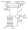
- the FIG. 1 is a depiction of an exemplary prior art evaporator system 100 of a drum-type steam generator that comprises an evaporator 102 and a steam drum 104 .
- the steam drum 104 is in fluid communication with the evaporator 102 .
- the steam drum 104 is both downstream and upstream of the evaporator 102 , i.e., they lie in a recycle loop.
- the load on the evaporator 102 changes more water is drawn from the steam drum 104 .
- the water level in the steam drum 104 drops. Feed water is then introduced to the steam drum 104 to maintain the predetermined operating water levels.
- the steam drum 104 is therefore sized based on the steam needs for the drum-type steam generator. However, when additional requirements such as the water hold time exceeds the normal steam drum 104 water storage level for a single drum, it is desirable to increase the size of the steam drum 104 .
- the water hold time (also sometimes termed the “holdup time”) is based on the measured liquid volume between normal water level (NWL) and the lowest (also sometimes referred to as the “lo-lo”) water level trip.
- the lowest water trip level is the minimum level at which there will be no danger of overheating any part of the steam generator during operation. This lowest water level is generally about 30 centimeters (about 1 foot) above the bottom of the drum, but varies according to drum diameter.
- the normal water level is set below the high water level, as needed for water level measurement accuracy, margin to control feedwater flow and steam purity.
- the location of normal water level results in about 15 seconds to 30 seconds of water volume (depending upon the flow rate) between the normal water level and the water level trip.
- the volume of water contained in the drum at these different heights can be calculated using simple formulas for the area of a circular segment.
- a system comprising an evaporator; a water reservoir in fluid communication with the evaporator; the water reservoir being located upstream of the evaporator; and a first steam drum in fluid communication with the evaporator; the first steam drum being located downstream of the evaporator; where the water reservoir is operative to supply feedwater to the evaporator while maintaining a predetermined water level in the first steam drum.
- a method comprising discharging feed water from a water reservoir to an evaporator; where the water reservoir lies upstream of the evaporator and is in fluid communication with the evaporator; and discharging water and steam from the evaporator to a first steam drum; where the evaporator lies upstream of the first steam drum and in fluid communication with the first steam drum; where an amount of water discharged from the water reservoir to the evaporator is effective to increase the water level in the first steam drum to a desired level.
- FIG. 1 is a depiction of an exemplary prior art evaporator system that comprises an evaporator and a steam drum;
- FIG. 2 depicts an exemplary system that comprises an evaporator, a steam drum and a water reservoir that are in fluid communication with one another;
- FIG. 3 depicts an exemplary system that comprises an evaporator, two steam drums and a water reservoir that are in fluid communication with one another.
- an evaporator system that comprises an evaporator, a steam drum and a reservoir.
- the reservoir is used for holding additional water that is supplied to the evaporator and allows for an increase in the water hold time in the system.
- a method of increasing the water hold time by providing a water reservoir, which holds water that is supplied to the evaporator when the water level in the steam drum decreases from the normal level.
- the normal level will hereinafter be referred to as a predetermined level.
- the evaporator system disclosed herein may be part of a drum-type steam generation system with natural or forced circulation such as heat recovery generation system, steam generation solar receivers, fossil fuel fired steam generation systems and other systems where an increase in the volume of the steam drum is desired to increase water hold up time, but where there are space limitations.
- FIG. 2 depicts a system 200 that comprises an evaporator 202 , a steam drum 204 and a water reservoir 206 that are in fluid communication with one another.
- the evaporator 202 is disposed upstream of the steam drum 204 and downstream of the water reservoir 206 .
- Feed water is fed into the water reservoir 206 via a valve 208 .
- the valve 208 is a flow control valve.
- the water from the water reservoir 206 is fed to the evaporator 202 , where it is converted into steam and water.
- the water and steam are then fed from the evaporator 202 into the steam drum 204 , where the steam is separated from the water.
- the steam is discharged to a superheater or to a turbine to generate energy, while the water in the steam drum 204 is recycled to the water reservoir 206 where it mixes with the feed water before being fed to the evaporator 202 .
- Both the steam drum 204 and the water reservoir 206 are equipped with level sensors to detect when desired liquid levels (e.g., water levels) deviate from desired values.
- the steam drum 204 comprises a first water level indicator, which is activated when the water level increases above a certain level (e.g., a high water level indicator), drops below a certain desired level (e.g., a low water level indicator) and control the feed water to the reservoir to maintain the predetermined water level.
- the predetermined water level lies between the high water level and the low water level.
- the water reservoir 206 also comprises a second water level indicator, which is activated when the water level decreases below a certain desired level (e.g., a low water level trip).
- the water level indicators may be floats, a manometer (e.g., a distilled water column or a mercury column), conductivity probes or the like, or a combination thereof.
- the level of water in the steam drum 204 may decrease below the desired level.
- the water level decreases below the predetermined level as indicated by the water level indicator, feed water flow to the water reservoir is increased.
- the increased water flow from the water reservoir 206 is introduced into the evaporator 202 to comply with the requirement for additional steam, while at the same time compensating for the loss of water from the steam drum 204 .
- feed water flow to the water reservoir is decreased.
- the reduced water flow from the water reservoir 206 is introduced into the evaporator 202 to comply with the requirement for a lower rate of steam-water flow into the steam drum 204 .
- water is fed into the water reservoir 206 via the valve 208 to maintain the water level to the predetermined level.
- the presence of the water reservoir 206 in the evaporation system 200 can thus be used to minimize space requirements in at least one direction.
- the system comprising the water reservoir is shorter than an equivalent system that does not contain the water reservoir when both systems utilize an equivalent drum diameter, hold up time and produce an equivalent amount of steam.
- the steam drum 204 would have to be longer, which depending on the arrangement may be difficult to fit into a confined space or the diameter would have to be increased.
- the thickness of the walls of the steam drum 204 would have to be increased to the point where the stresses in these walls would increase significantly. The use of a water reservoir 206 prevents these problems.
- the evaporation system 200 comprises two steam drums—a first steam drum 204 and a second steam drum 214 in fluid communication with the water reservoir 206 and the evaporator 202 .
- the first steam drum 204 and the second steam drum 214 may be in fluid communication with one another.
- Steam and water from the evaporator 202 can be discharged to the first steam drum 204 and to the second steam drum 214 .
- water and steam from the first steam drum 204 can be discharged to the second steam drum 214 .
- water and steam from the second steam drum 214 can be discharged to the first steam drum 204 .
- the system can have more than two drums.
- the evaporation system 200 may comprise a plurality of steam drums in fluid communication with the water reservoir 206 and the evaporator 202 .
- the two steam drums 204 and 214 function in conjunction with the water reservoir 206 and the evaporator 202 in the same manner as the single steam drum 204 in the FIG. 2 .
- water from the water reservoir 206 is introduced into the evaporator 202 to comply with the requirement for additional steam, while at the same time compensating for the loss of water in the steam drum 204 or the steam drum 214 . If the level of water in the steam drums 204 or 214 decreases below the desired level then additional feedwater is supplied to the water reservoir 206 via the valve 208 .
- first,” “second,” “third” etc. may be used herein to describe various elements, components, regions, layers and/or sections, these elements, components, regions, layers and/or sections should not be limited by these terms. These terms are only used to distinguish one element, component, region, layer or section from another element, component, region, layer or section. Thus, “a first element,” “component,” “region,” “layer” or “section” discussed below could be termed a second element, component, region, layer or section without departing from the teachings herein.
- relative terms such as “lower” or “bottom” and “upper” or “top,” may be used herein to describe one element's relationship to another element as illustrated in the Figures. It will be understood that relative terms are intended to encompass different orientations of the device in addition to the orientation depicted in the Figures. For example, if the device in one of the figures is turned over, elements described as being on the “lower” side of other elements would then be oriented on “upper” sides of the other elements. The exemplary term “lower,” can therefore, encompasses both an orientation of “lower” and “upper,” depending on the particular orientation of the figure.
Abstract
Description
Claims (15)
Priority Applications (6)
| Application Number | Priority Date | Filing Date | Title |
|---|---|---|---|
| US13/313,868 US8851024B2 (en) | 2011-12-07 | 2011-12-07 | Water reservoir for a steam generation system and method of use thereof |
| CN201280060244.8A CN104105923B (en) | 2011-12-07 | 2012-12-06 | Water receiver and using method thereof for steam generating system |
| PCT/EP2012/074622 WO2013083684A1 (en) | 2011-12-07 | 2012-12-06 | Water reservoir for a steam generation system and method of use thereof |
| EP12798710.5A EP2788684A1 (en) | 2011-12-07 | 2012-12-06 | Water reservoir for a steam generation system and method of use thereof |
| ZA2014/03650A ZA201403650B (en) | 2011-12-07 | 2014-05-20 | Water reservoir for a steam generation system and method of use thereof |
| MA37169A MA35838B1 (en) | 2011-12-07 | 2014-06-30 | Water tank for steam production system and method of use |
Applications Claiming Priority (1)
| Application Number | Priority Date | Filing Date | Title |
|---|---|---|---|
| US13/313,868 US8851024B2 (en) | 2011-12-07 | 2011-12-07 | Water reservoir for a steam generation system and method of use thereof |
Publications (2)
| Publication Number | Publication Date |
|---|---|
| US20130145998A1 US20130145998A1 (en) | 2013-06-13 |
| US8851024B2 true US8851024B2 (en) | 2014-10-07 |
Family
ID=47326141
Family Applications (1)
| Application Number | Title | Priority Date | Filing Date |
|---|---|---|---|
| US13/313,868 Expired - Fee Related US8851024B2 (en) | 2011-12-07 | 2011-12-07 | Water reservoir for a steam generation system and method of use thereof |
Country Status (6)
| Country | Link |
|---|---|
| US (1) | US8851024B2 (en) |
| EP (1) | EP2788684A1 (en) |
| CN (1) | CN104105923B (en) |
| MA (1) | MA35838B1 (en) |
| WO (1) | WO2013083684A1 (en) |
| ZA (1) | ZA201403650B (en) |
Families Citing this family (4)
| Publication number | Priority date | Publication date | Assignee | Title |
|---|---|---|---|---|
| BE1022566A9 (en) * | 2014-11-21 | 2017-07-06 | Cockerill Maintenance & Ingenierie Sa | BALLOON STEAM GENERATOR HAVING REDUCED WALL THICKNESS USING MULTI-BALLOON CONFIGURATION |
| US20160284445A1 (en) * | 2015-03-28 | 2016-09-29 | Y Generation Technologies Company Limited | Energy efficient copper wire production system |
| CN110686226B (en) * | 2019-10-18 | 2021-08-27 | 百铭服饰(福建)有限公司 | Auxiliary self-locking protection mechanism for electric steam boiler |
| CN112097241B (en) * | 2020-08-20 | 2022-12-20 | 中国能源建设集团华东电力试验研究院有限公司 | Steam turbine FCB test drum water level control feedforward structure and control method thereof |
Citations (9)
| Publication number | Priority date | Publication date | Assignee | Title |
|---|---|---|---|---|
| US4207842A (en) * | 1977-06-16 | 1980-06-17 | Bbc Brown, Boveri & Co. | Mixed-flow feedwater heater having a regulating device |
| US4745757A (en) * | 1987-02-24 | 1988-05-24 | Energy Services Inc. | Combined heat recovery and make-up water heating system |
| US5326081A (en) * | 1990-07-04 | 1994-07-05 | A. Ahlstrom Corporation | Method and apparatus for cooling hot gases |
| US5727505A (en) * | 1992-09-07 | 1998-03-17 | Siemens Aktiengesellschaft | Apparatus for separating water and steam |
| US5762031A (en) * | 1997-04-28 | 1998-06-09 | Gurevich; Arkadiy M. | Vertical drum-type boiler with enhanced circulation |
| US6155054A (en) * | 1998-08-18 | 2000-12-05 | Asea Brown Boveri Ag | Steam power plant and method of and cleaning its steam/water cycle |
| US7587996B2 (en) * | 2006-06-07 | 2009-09-15 | Babcock & Wilcox Power Generation Group, Inc. | Circulation system for sliding pressure steam generator |
| US20110265444A1 (en) * | 2010-04-30 | 2011-11-03 | Bellows James C | Energy recovery and steam supply for power augmentation in a combined cycle power generation system |
| US20130118477A1 (en) * | 2011-11-16 | 2013-05-16 | Babcock & Wilcox Power Generation Group, Inc. | Freeze protection system for solar receiver |
Family Cites Families (14)
| Publication number | Priority date | Publication date | Assignee | Title |
|---|---|---|---|---|
| GB294685A (en) * | 1927-04-28 | 1928-07-30 | Wilfred Rothery Wood | Improvements in water tube boilers |
| FR678909A (en) * | 1928-07-24 | 1930-04-07 | Int Comb Eng Corp | Improvements in the construction of water tube boilers |
| CH167902A (en) * | 1932-11-28 | 1934-03-15 | Werner Gfeller Ernst | Method for accelerated temperature equalization in a heated liquid which is under its vapor pressure. |
| GB1191689A (en) * | 1967-12-27 | 1970-05-13 | Vapor Corp | Heat Exchanging Apparatus |
| JPS55112809A (en) * | 1979-02-21 | 1980-09-01 | Hitachi Ltd | Method of running combined-cycle power plant and controller therefor |
| ES2001332A6 (en) * | 1985-07-02 | 1988-05-16 | Framatome Sa | Steam generator with a distributor, particularly for a nuclear-power station. |
| US5419285A (en) * | 1994-04-25 | 1995-05-30 | Henry Vogt Machine Co. | Boiler economizer and control system |
| CN2298428Y (en) * | 1997-09-02 | 1998-11-25 | 李德科 | High efficient energy saving boiler drum |
| US7053341B2 (en) * | 2004-02-12 | 2006-05-30 | General Electric Company | Method and apparatus for drum level control for drum-type boilers |
| US7931041B2 (en) * | 2007-12-19 | 2011-04-26 | General Electric Company | System and method for controlling liquid level in a vessel |
| JP5191361B2 (en) * | 2008-11-21 | 2013-05-08 | 株式会社日立製作所 | Liquid level control system. |
| US8757105B2 (en) * | 2008-12-08 | 2014-06-24 | General Electric Company | System and method for controlling liquid level in a vessel |
| WO2011104328A2 (en) * | 2010-02-26 | 2011-09-01 | Siemens Aktiengesellschaft | Apparatus and method for generating superheated steam using solar energy on the basis of the natural circulation concept, and use of the superheated steam |
| US9518731B2 (en) * | 2011-03-23 | 2016-12-13 | General Electric Technology Gmbh | Method and configuration to reduce fatigue in steam drums |
-
2011
- 2011-12-07 US US13/313,868 patent/US8851024B2/en not_active Expired - Fee Related
-
2012
- 2012-12-06 EP EP12798710.5A patent/EP2788684A1/en not_active Withdrawn
- 2012-12-06 CN CN201280060244.8A patent/CN104105923B/en not_active Expired - Fee Related
- 2012-12-06 WO PCT/EP2012/074622 patent/WO2013083684A1/en active Application Filing
-
2014
- 2014-05-20 ZA ZA2014/03650A patent/ZA201403650B/en unknown
- 2014-06-30 MA MA37169A patent/MA35838B1/en unknown
Patent Citations (10)
| Publication number | Priority date | Publication date | Assignee | Title |
|---|---|---|---|---|
| US4207842A (en) * | 1977-06-16 | 1980-06-17 | Bbc Brown, Boveri & Co. | Mixed-flow feedwater heater having a regulating device |
| US4745757A (en) * | 1987-02-24 | 1988-05-24 | Energy Services Inc. | Combined heat recovery and make-up water heating system |
| US5326081A (en) * | 1990-07-04 | 1994-07-05 | A. Ahlstrom Corporation | Method and apparatus for cooling hot gases |
| US5727505A (en) * | 1992-09-07 | 1998-03-17 | Siemens Aktiengesellschaft | Apparatus for separating water and steam |
| US5762031A (en) * | 1997-04-28 | 1998-06-09 | Gurevich; Arkadiy M. | Vertical drum-type boiler with enhanced circulation |
| US6155054A (en) * | 1998-08-18 | 2000-12-05 | Asea Brown Boveri Ag | Steam power plant and method of and cleaning its steam/water cycle |
| US7587996B2 (en) * | 2006-06-07 | 2009-09-15 | Babcock & Wilcox Power Generation Group, Inc. | Circulation system for sliding pressure steam generator |
| US20110265444A1 (en) * | 2010-04-30 | 2011-11-03 | Bellows James C | Energy recovery and steam supply for power augmentation in a combined cycle power generation system |
| US8539750B2 (en) * | 2010-04-30 | 2013-09-24 | Siemens Energy, Inc. | Energy recovery and steam supply for power augmentation in a combined cycle power generation system |
| US20130118477A1 (en) * | 2011-11-16 | 2013-05-16 | Babcock & Wilcox Power Generation Group, Inc. | Freeze protection system for solar receiver |
Also Published As
| Publication number | Publication date |
|---|---|
| MA35838B1 (en) | 2014-12-01 |
| ZA201403650B (en) | 2015-08-26 |
| CN104105923B (en) | 2016-07-06 |
| US20130145998A1 (en) | 2013-06-13 |
| WO2013083684A1 (en) | 2013-06-13 |
| EP2788684A1 (en) | 2014-10-15 |
| CN104105923A (en) | 2014-10-15 |
Similar Documents
| Publication | Publication Date | Title |
|---|---|---|
| US8851024B2 (en) | Water reservoir for a steam generation system and method of use thereof | |
| EP2390565B1 (en) | Heat Recovery Steam Generation System and Method for Controlling a Water Level of a Drum in a Heat Recovery Steam Generation System for a Combined Cycle Power Plant | |
| CN102282628B (en) | Reactor vessel coolant deflector shield | |
| US9518481B2 (en) | Method for operating a recirculating waste heat steam generator | |
| JP2009150644A (en) | System and method for controlling liquid level in vessel | |
| US20140334591A1 (en) | Passive containment spray system | |
| US9869467B2 (en) | Once-through steam generator | |
| CN104969301A (en) | Pressurized water reactor depressurization system | |
| JP5276362B2 (en) | Cavitation removal system and power plant water supply device | |
| CN103811089A (en) | Nuclear power station secondary circuit deaerator and liquid level control method thereof | |
| US20160208657A1 (en) | Operating method for starting a once-through steam generator heated using solar thermal energy | |
| CN108346476A (en) | Reactor and divide pot type voltage-stablizer | |
| CA2784276C (en) | Nuclear power plant | |
| JP2010112773A (en) | Nuclear power plant | |
| US9208905B2 (en) | Auxiliary feedwater valve control apparatus of steam generator | |
| KR20090050596A (en) | A steam generating apparatus | |
| JP6312935B2 (en) | Deaerator (option) | |
| JP2017067494A (en) | Nuclear reactor water injection device and nuclear reactor power generation plant | |
| JPH048682B2 (en) | ||
| JP7443008B2 (en) | Steam turbine plant, control device, and water quality management method for steam turbine plant | |
| CN104990060B (en) | A kind of Steam Cooler System passive resistance protection device | |
| CN208027759U (en) | Reactor and divide pot type voltage-stablizer | |
| RU2528657C2 (en) | Device for simultaneous evaporation and proportioning of evaporated fluid and method to this method | |
| JP2007101537A (en) | Improved online steam flow velocity measurement device and method | |
| JPS5842778Y2 (en) | Drain recovery processing equipment |
Legal Events
| Date | Code | Title | Description |
|---|---|---|---|
| AS | Assignment |
Owner name: ALSTOM TECHNOLOGY LTD, SWITZERLAND Free format text: ASSIGNMENT OF ASSIGNORS INTEREST;ASSIGNOR:WILHELM, BRUCE W.;REEL/FRAME:027707/0836 Effective date: 20120215 |
|
| FEPP | Fee payment procedure |
Free format text: PAYOR NUMBER ASSIGNED (ORIGINAL EVENT CODE: ASPN); ENTITY STATUS OF PATENT OWNER: LARGE ENTITY |
|
| STCF | Information on status: patent grant |
Free format text: PATENTED CASE |
|
| AS | Assignment |
Owner name: GENERAL ELECTRIC TECHNOLOGY GMBH, SWITZERLAND Free format text: CHANGE OF NAME;ASSIGNOR:ALSTOM TECHNOLOGY LTD;REEL/FRAME:039714/0578 Effective date: 20151102 |
|
| MAFP | Maintenance fee payment |
Free format text: PAYMENT OF MAINTENANCE FEE, 4TH YEAR, LARGE ENTITY (ORIGINAL EVENT CODE: M1551) Year of fee payment: 4 |
|
| FEPP | Fee payment procedure |
Free format text: MAINTENANCE FEE REMINDER MAILED (ORIGINAL EVENT CODE: REM.); ENTITY STATUS OF PATENT OWNER: LARGE ENTITY |
|
| LAPS | Lapse for failure to pay maintenance fees |
Free format text: PATENT EXPIRED FOR FAILURE TO PAY MAINTENANCE FEES (ORIGINAL EVENT CODE: EXP.); ENTITY STATUS OF PATENT OWNER: LARGE ENTITY |
|
| STCH | Information on status: patent discontinuation |
Free format text: PATENT EXPIRED DUE TO NONPAYMENT OF MAINTENANCE FEES UNDER 37 CFR 1.362 |
|
| FP | Lapsed due to failure to pay maintenance fee |
Effective date: 20221007 |