US8822024B2 - Method of producing a self-healing membrane - Google Patents

Method of producing a self-healing membrane Download PDF

Info

Publication number
US8822024B2
US8822024B2 US11/922,859 US92285906A US8822024B2 US 8822024 B2 US8822024 B2 US 8822024B2 US 92285906 A US92285906 A US 92285906A US 8822024 B2 US8822024 B2 US 8822024B2
Authority
US
United States
Prior art keywords
blisters
plastic
layer
membrane
microcapsules
Prior art date
Legal status (The legal status is an assumption and is not a legal conclusion. Google has not performed a legal analysis and makes no representation as to the accuracy of the status listed.)
Expired - Fee Related, expires
Application number
US11/922,859
Other versions
US20090035551A1 (en
Inventor
Rolf Luchsinger
Thomas Speck
Olga Speck
Current Assignee (The listed assignees may be inaccurate. Google has not performed a legal analysis and makes no representation or warranty as to the accuracy of the list.)
Prospective Concepts AG
Original Assignee
Prospective Concepts AG
Priority date (The priority date is an assumption and is not a legal conclusion. Google has not performed a legal analysis and makes no representation as to the accuracy of the date listed.)
Filing date
Publication date
Application filed by Prospective Concepts AG filed Critical Prospective Concepts AG
Assigned to PROSPECTIVE CONCEPTS AG reassignment PROSPECTIVE CONCEPTS AG ASSIGNMENT OF ASSIGNORS INTEREST (SEE DOCUMENT FOR DETAILS). Assignors: LUCHSINGER, ROLF, SPECK, OLGA, SPECK, THOMAS
Publication of US20090035551A1 publication Critical patent/US20090035551A1/en
Application granted granted Critical
Publication of US8822024B2 publication Critical patent/US8822024B2/en
Expired - Fee Related legal-status Critical Current
Adjusted expiration legal-status Critical

Links

Images

Classifications

    • BPERFORMING OPERATIONS; TRANSPORTING
    • B29WORKING OF PLASTICS; WORKING OF SUBSTANCES IN A PLASTIC STATE IN GENERAL
    • B29CSHAPING OR JOINING OF PLASTICS; SHAPING OF MATERIAL IN A PLASTIC STATE, NOT OTHERWISE PROVIDED FOR; AFTER-TREATMENT OF THE SHAPED PRODUCTS, e.g. REPAIRING
    • B29C73/00Repairing of articles made from plastics or substances in a plastic state, e.g. of articles shaped or produced by using techniques covered by this subclass or subclass B29D
    • B29C73/16Auto-repairing or self-sealing arrangements or agents
    • B29C73/18Auto-repairing or self-sealing arrangements or agents the article material itself being self-sealing, e.g. by compression
    • B29C73/20Auto-repairing or self-sealing arrangements or agents the article material itself being self-sealing, e.g. by compression the article material only consisting in part of a deformable sealing material
    • BPERFORMING OPERATIONS; TRANSPORTING
    • B29WORKING OF PLASTICS; WORKING OF SUBSTANCES IN A PLASTIC STATE IN GENERAL
    • B29CSHAPING OR JOINING OF PLASTICS; SHAPING OF MATERIAL IN A PLASTIC STATE, NOT OTHERWISE PROVIDED FOR; AFTER-TREATMENT OF THE SHAPED PRODUCTS, e.g. REPAIRING
    • B29C44/00Shaping by internal pressure generated in the material, e.g. swelling or foaming ; Producing porous or cellular expanded plastics articles
    • B29C44/34Auxiliary operations
    • B29C44/3438Bursting the cell walls by a sudden pressure release
    • BPERFORMING OPERATIONS; TRANSPORTING
    • B29WORKING OF PLASTICS; WORKING OF SUBSTANCES IN A PLASTIC STATE IN GENERAL
    • B29CSHAPING OR JOINING OF PLASTICS; SHAPING OF MATERIAL IN A PLASTIC STATE, NOT OTHERWISE PROVIDED FOR; AFTER-TREATMENT OF THE SHAPED PRODUCTS, e.g. REPAIRING
    • B29C67/00Shaping techniques not covered by groups B29C39/00 - B29C65/00, B29C70/00 or B29C73/00
    • B29C67/24Shaping techniques not covered by groups B29C39/00 - B29C65/00, B29C70/00 or B29C73/00 characterised by the choice of material
    • B29C67/247Moulding polymers or prepolymers containing ingredients in a frangible packaging, e.g. microcapsules
    • BPERFORMING OPERATIONS; TRANSPORTING
    • B32LAYERED PRODUCTS
    • B32BLAYERED PRODUCTS, i.e. PRODUCTS BUILT-UP OF STRATA OF FLAT OR NON-FLAT, e.g. CELLULAR OR HONEYCOMB, FORM
    • B32B27/00Layered products comprising a layer of synthetic resin
    • B32B27/12Layered products comprising a layer of synthetic resin next to a fibrous or filamentary layer
    • BPERFORMING OPERATIONS; TRANSPORTING
    • B32LAYERED PRODUCTS
    • B32BLAYERED PRODUCTS, i.e. PRODUCTS BUILT-UP OF STRATA OF FLAT OR NON-FLAT, e.g. CELLULAR OR HONEYCOMB, FORM
    • B32B27/00Layered products comprising a layer of synthetic resin
    • B32B27/18Layered products comprising a layer of synthetic resin characterised by the use of special additives
    • BPERFORMING OPERATIONS; TRANSPORTING
    • B60VEHICLES IN GENERAL
    • B60CVEHICLE TYRES; TYRE INFLATION; TYRE CHANGING; CONNECTING VALVES TO INFLATABLE ELASTIC BODIES IN GENERAL; DEVICES OR ARRANGEMENTS RELATED TO TYRES
    • B60C19/00Tyre parts or constructions not otherwise provided for
    • B60C19/12Puncture preventing arrangements
    • B60C19/122Puncture preventing arrangements disposed inside of the inner liner
    • BPERFORMING OPERATIONS; TRANSPORTING
    • B29WORKING OF PLASTICS; WORKING OF SUBSTANCES IN A PLASTIC STATE IN GENERAL
    • B29CSHAPING OR JOINING OF PLASTICS; SHAPING OF MATERIAL IN A PLASTIC STATE, NOT OTHERWISE PROVIDED FOR; AFTER-TREATMENT OF THE SHAPED PRODUCTS, e.g. REPAIRING
    • B29C67/00Shaping techniques not covered by groups B29C39/00 - B29C65/00, B29C70/00 or B29C73/00
    • B29C67/24Shaping techniques not covered by groups B29C39/00 - B29C65/00, B29C70/00 or B29C73/00 characterised by the choice of material
    • B29C67/246Moulding high reactive monomers or prepolymers, e.g. by reaction injection moulding [RIM], liquid injection moulding [LIM]
    • BPERFORMING OPERATIONS; TRANSPORTING
    • B29WORKING OF PLASTICS; WORKING OF SUBSTANCES IN A PLASTIC STATE IN GENERAL
    • B29KINDEXING SCHEME ASSOCIATED WITH SUBCLASSES B29B, B29C OR B29D, RELATING TO MOULDING MATERIALS OR TO MATERIALS FOR MOULDS, REINFORCEMENTS, FILLERS OR PREFORMED PARTS, e.g. INSERTS
    • B29K2075/00Use of PU, i.e. polyureas or polyurethanes or derivatives thereof, as moulding material
    • BPERFORMING OPERATIONS; TRANSPORTING
    • B29WORKING OF PLASTICS; WORKING OF SUBSTANCES IN A PLASTIC STATE IN GENERAL
    • B29KINDEXING SCHEME ASSOCIATED WITH SUBCLASSES B29B, B29C OR B29D, RELATING TO MOULDING MATERIALS OR TO MATERIALS FOR MOULDS, REINFORCEMENTS, FILLERS OR PREFORMED PARTS, e.g. INSERTS
    • B29K2083/00Use of polymers having silicon, with or without sulfur, nitrogen, oxygen, or carbon only, in the main chain, as moulding material
    • BPERFORMING OPERATIONS; TRANSPORTING
    • B29WORKING OF PLASTICS; WORKING OF SUBSTANCES IN A PLASTIC STATE IN GENERAL
    • B29LINDEXING SCHEME ASSOCIATED WITH SUBCLASS B29C, RELATING TO PARTICULAR ARTICLES
    • B29L2030/00Pneumatic or solid tyres or parts thereof
    • BPERFORMING OPERATIONS; TRANSPORTING
    • B32LAYERED PRODUCTS
    • B32BLAYERED PRODUCTS, i.e. PRODUCTS BUILT-UP OF STRATA OF FLAT OR NON-FLAT, e.g. CELLULAR OR HONEYCOMB, FORM
    • B32B2250/00Layers arrangement
    • B32B2250/022 layers
    • BPERFORMING OPERATIONS; TRANSPORTING
    • B32LAYERED PRODUCTS
    • B32BLAYERED PRODUCTS, i.e. PRODUCTS BUILT-UP OF STRATA OF FLAT OR NON-FLAT, e.g. CELLULAR OR HONEYCOMB, FORM
    • B32B2255/00Coating on the layer surface
    • B32B2255/02Coating on the layer surface on fibrous or filamentary layer
    • BPERFORMING OPERATIONS; TRANSPORTING
    • B32LAYERED PRODUCTS
    • B32BLAYERED PRODUCTS, i.e. PRODUCTS BUILT-UP OF STRATA OF FLAT OR NON-FLAT, e.g. CELLULAR OR HONEYCOMB, FORM
    • B32B2255/00Coating on the layer surface
    • B32B2255/10Coating on the layer surface on synthetic resin layer or on natural or synthetic rubber layer
    • BPERFORMING OPERATIONS; TRANSPORTING
    • B32LAYERED PRODUCTS
    • B32BLAYERED PRODUCTS, i.e. PRODUCTS BUILT-UP OF STRATA OF FLAT OR NON-FLAT, e.g. CELLULAR OR HONEYCOMB, FORM
    • B32B2307/00Properties of the layers or laminate
    • B32B2307/70Other properties
    • B32B2307/762Self-repairing, self-healing
    • BPERFORMING OPERATIONS; TRANSPORTING
    • B32LAYERED PRODUCTS
    • B32BLAYERED PRODUCTS, i.e. PRODUCTS BUILT-UP OF STRATA OF FLAT OR NON-FLAT, e.g. CELLULAR OR HONEYCOMB, FORM
    • B32B2419/00Buildings or parts thereof
    • BPERFORMING OPERATIONS; TRANSPORTING
    • B32LAYERED PRODUCTS
    • B32BLAYERED PRODUCTS, i.e. PRODUCTS BUILT-UP OF STRATA OF FLAT OR NON-FLAT, e.g. CELLULAR OR HONEYCOMB, FORM
    • B32B2605/00Vehicles
    • YGENERAL TAGGING OF NEW TECHNOLOGICAL DEVELOPMENTS; GENERAL TAGGING OF CROSS-SECTIONAL TECHNOLOGIES SPANNING OVER SEVERAL SECTIONS OF THE IPC; TECHNICAL SUBJECTS COVERED BY FORMER USPC CROSS-REFERENCE ART COLLECTIONS [XRACs] AND DIGESTS
    • Y10TECHNICAL SUBJECTS COVERED BY FORMER USPC
    • Y10TTECHNICAL SUBJECTS COVERED BY FORMER US CLASSIFICATION
    • Y10T428/00Stock material or miscellaneous articles
    • Y10T428/249921Web or sheet containing structurally defined element or component
    • Y10T428/249953Composite having voids in a component [e.g., porous, cellular, etc.]
    • Y10T428/249981Plural void-containing components

Definitions

  • the present invention relates to a method for producing a membrane which, following mechanical injury in the sense of a puncture or a bullet hole or penetration wound with a small-caliber weapon, is capable of closing this injury without external intervention.
  • the present invention is concerned with pneumatic structures such as have been known, for example, from the European Patent Specifications EP 1 239 756, EP 1 210 489, the European Patent Applications EP 03 700 039 and EP 03 764 875 and the international publication WO 2005/007991.
  • EP 1 239 756 discloses a pneumatic mattress or bench seat which requires no horizontal support as underlay. It can quickly be made ready for use and can be stowed away again with little space requirement.
  • the arrangement of the supporting chambers can be configured in such a manner that the mattress itself is configured in the manner of a supporting structure.
  • EP 1 210 489 discloses a pneumatic structural element in the manner of an inflatable tubular hollow body which can absorb without buckling tensile and thrust forces which may arise.
  • the structural elements can easily be joined together to form more complex components such as roofs or bridges, which may be erected very rapidly.
  • EP 1 554 158 discloses an adaptive pneumatic seat and backrest for vehicles and airplanes which, despite the given basic structure of the air chambers, offers high seat comfort corresponding to conventional foam cushions and brings a discernible saving in weight compared with these.
  • WO 2004/009400 discloses an adaptive pneumatic seat and backrests for vehicles and airplanes which, despite the given basic structure of the air chambers, offers high seat comfort corresponding to conventional foam cushions and brings a discernible saving in weight compared with these and in addition, can be simply designed onto existing seat shell structures.
  • WO 2005/007991 discloses a pneumatic support.
  • the structural element can easily be joined together to form more complex components such as roofs or bridges which may be erected very rapidly.
  • the structural element can easily be joined to conventional existing building constructions.
  • such pneumatic structures have in common that they weigh comparatively little, i.e. they are easily transportable since their membrane takes up little space in the deflated state and can be stored and transported in a space-saving manner.
  • pneumatic structures comprise on the one hand large-area structures having areas of several hundred to several thousand square meters with small excess pressures of the order of magnitude of 10 to 500 mbar, on the other hand small-volume and small-area structures having excess pressures of 50-200 mbar, as in the case of pneumatic seats for example.
  • the object of the present invention is to provide a method whereby a membrane used as an envelope in such said pneumatic structures can be prepared and processed in such a manner that a hole of said type in this membrane closes without intervention.
  • FIG. 1 illustrates a cross-section through a membrane produced according to the invention
  • FIG. 2 illustrates a first type of injury
  • FIG. 3 illustrates FIG. 2 after removal of the injurious object
  • FIG. 4 illustrates the first type of injury on an enlarged scale
  • FIG. 5 illustrates a second type of injury during the self-healing process
  • FIG. 6 illustrates a plan view of a film to be applied to the layer
  • FIG. 7 illustrates, in plain view, a variant of the process step of FIG. 6 ;
  • FIG. 8 illustrates a cross-section of a second variant for the process step according to FIG. 6 .
  • FIG. 1 shows a membrane as an envelope of a pneumatic structure, the airtight membrane is designated by the reference numeral 1 .
  • the membrane 1 can be, for example, fabric made of polyester, nylon, fiberglass, aramides coated with a plastic such as PVC, PU, silicone or Teflon® but also flexible films made of such materials if the tensile stresses which occur are within permissible material properties.
  • a thin layer 2 of a plastic containing a plurality of small gas bubbles 3 is applied to the inside of this membrane 1 by means of one of the known techniques, i.e., for example, by wiping, rolling or spraying.
  • Polyurethane for example, is used as the plastic here.
  • PVC-coated polyester fabric from Duraskin® (Type III, Verseldag, Krefeld) was coated with different commercially available closed-pore polyurethane foams according to the manufacturer's instructions.
  • the two-component polyurethane foam Polyfoam F5 (Polyconform GmbH) proved to be particularly suitable here.
  • the aforementioned gas bubbles 3 located in the plastic of the layer 2 can either be incorporated therein by a rapid mixing process of the plastic. However, they can also be formed by the polymerization process and then left in the plastic by omitting a vacuum treatment. Gas bubbles in the range of 10 ⁇ -200 ⁇ have proved successful for the desired self-healing process of an injury to the membrane 1 . (An arrangement comprising a stereomicroscope (Olympus, SZX9) and connected digital camera (Olympus DP12, Japan) was advantageous for studying the membrane 1 coated by the layer 2 ).
  • the membrane 1 was then polymerized at elevated pressure.
  • the polymerization parameters such as pressure and temperature can vary, being specific to the plastic.
  • the elevated pressure typically 2 bar, is important.
  • the improved reaction properties can be attributed to the elevated internal pressure of the foam cells or bubbles ( 3 ) and also to conformational or structural changes inside the foam which have a positive influence on the repair, i.e. sealing, behavior merely as a result of a different arrangement of the material.
  • the repair behavior could also be further improved by determining the amount of plastic to be polymerized applied per unit area; better results in the self-healing or repair behavior were achieved with an amount of coating in the range of 1 to 2 g for an area of about 20 cm 2 (circular sample having a diameter of 5 cm) as compared with amounts of coating outside this range.
  • a coating amount of 1.6 g proved to be particularly advantageous. This corresponds to a quantity per 100 cm 2 of 5 to 10 g or an optimal quantity of 8 g of coating material.
  • FIG. 4 shows a section of the uppermost part of the fissure 5 .
  • a part of the layer 2 is pushed into the fissure 5 and is partially pressed therein by the escaping air; a process which can take seconds to minutes.
  • the cross-section of the hole is thereby reduced and the leakage flow severely suppressed.
  • the internal pressure can usually be maintained by external means such as compressors or, at low internal pressures of pneumatic structures, by fans, and in addition, this internal pressure is usually permanently monitored, there is sufficient time for an intervention in the sense of a repair to the envelope of the pneumatic structure.
  • a hole in the membrane is not a weakening if the force flow is interrupted as a result of the lower strength of its filling.
  • two-component plastics can also be used in a suitable form instead of pre-polymers.
  • FIG. 5 shows a first exemplary embodiment of a second step of this production method according to the invention.
  • a plurality of microcapsules 6 are mixed into the material of the layer 2 .
  • Such microcapsules typically having a diameter of about 100 ⁇ , contain, for example, a monomer, others contain an accelerator and/or a catalyst for effecting the polymerization of the monomer.
  • the monomer can also contain a solvent in which a suitable gas is dissolved under pressure.
  • Such techniques are known from plastics technology.
  • such microcapsules 6 can also contain a pre-polymer which preferably contains a solvent and a propellant gas dissolved therein under pressure.
  • microcapsules 6 are torn by an injury, a puncture or a penetration wound, the contents of a plurality of microcapsules 6 escape at the rim of the hole, forming a foam 7 which now hardens under the influence of the catalysts or the air humidity and permanently closes the hole 4 .
  • adhesion to the walls of the hole 4 also occurs if the plastic contained in the microcapsules 6 does not bind sealingly or only poorly binds to that of the layer 2 or that of the membrane 1 since a plurality of textile fibers are exposed and the plastic emerging from the microcapsules can adhere to their open ends. Otherwise, the plastic of the membrane coating must be matched to that of the layer 2 . Naturally and optimally, said plastics are matched to one another, and the sealing can thus be optimized.
  • FIG. 6 shows a plan view of a blister film 8 which either contains a monomer or, in a selected distribution, a monomer and a suitable polymerization partner or a moisture-curing pre-polymer with accelerator, in a plurality of blisters 9 .
  • the size of the blisters 9 can be selected and adapted in a broad framework so that, in conjunction with the distances a between the blisters 9 , this ensures that in the event of injuries to the membrane which go beyond the self-healing capability of the layer 7 , a plurality of such blisters 6 are torn.
  • a foam then forms, as described for FIG. 5 , which enters into the injury and polymerizes there.
  • a distance d>a is provided between the rows of blisters 9 at said distances a, which allows the blister film to be fastened to the layer 2 by gluing or welding.
  • the blisters 9 can be produced in any suitable shape and the surface coverage thereby optimized.
  • the size of the blisters 9 can also be varied widely.
  • FIG. 7 shows a variant of the exemplary embodiment from, also in plan view.
  • elongated blisters 10 are provided, for example, filled with a monomer.
  • other blisters 11 are arranged coincidentally (shown with dotted rims).
  • the shapes can also be selected differently here and the respective size ratios of the blisters 10 , 122 can be provided differently.
  • a strip d>a can also be provided to allow the blister film 8 to be glued or welded to the layer 2 , without injuring the blisters 10 , 11 .
  • FIG. 8 An alternative to the method examples in FIGS. 6 and 7 is shown in FIG. 8 .
  • a blister film 12 is applied thereto which, compared to the blister films 8 already described, additionally has a perforation extending into the surface, consisting of a plurality of small holes 13 which preferably have a diameter of 0.1 to 1.0 mm.
  • the blisters 9 again, for example, contain two components of a suitable plastic.
  • the polymerisation now takes place under pressure, as described for FIG. 1 .
  • the blister film 12 is fixed on the layer 2 by partial penetration of the layer 2 into the perforation.

Abstract

The invention relates to a membrane that heals on its own after being damaged mechanically as well as a method for producing said membrane which is used for pneumatic structures featuring an internal operating pressure of 10 mbar to 500 mbar. The inventive membrane is provided with a plastic layer on the pressure side, said plastic layer being interspersed with blisters that have a diameter ranging from 10μ to 200μ.

Description

BACKGROUND OF THE INVENTION
1. Technical Field
The present invention relates to a method for producing a membrane which, following mechanical injury in the sense of a puncture or a bullet hole or penetration wound with a small-caliber weapon, is capable of closing this injury without external intervention.
2. History of the Related Art
The present invention is concerned with pneumatic structures such as have been known, for example, from the European Patent Specifications EP 1 239 756, EP 1 210 489, the European Patent Applications EP 03 700 039 and EP 03 764 875 and the international publication WO 2005/007991.
EP 1 239 756 discloses a pneumatic mattress or bench seat which requires no horizontal support as underlay. It can quickly be made ready for use and can be stowed away again with little space requirement. The arrangement of the supporting chambers can be configured in such a manner that the mattress itself is configured in the manner of a supporting structure.
EP 1 210 489 discloses a pneumatic structural element in the manner of an inflatable tubular hollow body which can absorb without buckling tensile and thrust forces which may arise. The structural elements can easily be joined together to form more complex components such as roofs or bridges, which may be erected very rapidly.
EP 1 554 158 (EP 1 210 489) discloses an adaptive pneumatic seat and backrest for vehicles and airplanes which, despite the given basic structure of the air chambers, offers high seat comfort corresponding to conventional foam cushions and brings a discernible saving in weight compared with these.
WO 2004/009400 (EP 03 764 875) discloses an adaptive pneumatic seat and backrests for vehicles and airplanes which, despite the given basic structure of the air chambers, offers high seat comfort corresponding to conventional foam cushions and brings a discernible saving in weight compared with these and in addition, can be simply designed onto existing seat shell structures.
WO 2005/007991 discloses a pneumatic support. The structural element can easily be joined together to form more complex components such as roofs or bridges which may be erected very rapidly. In addition, the structural element can easily be joined to conventional existing building constructions.
Among other things, such pneumatic structures have in common that they weigh comparatively little, i.e. they are easily transportable since their membrane takes up little space in the deflated state and can be stored and transported in a space-saving manner.
These pneumatic structures comprise on the one hand large-area structures having areas of several hundred to several thousand square meters with small excess pressures of the order of magnitude of 10 to 500 mbar, on the other hand small-volume and small-area structures having excess pressures of 50-200 mbar, as in the case of pneumatic seats for example.
In all these cases the escape of compressed gas, usually air, should be avoided in order to maintain said internal operating pressure at least at the necessary minimum.
SUMMARY OF THE INVENTION
The object of the present invention is to provide a method whereby a membrane used as an envelope in such said pneumatic structures can be prepared and processed in such a manner that a hole of said type in this membrane closes without intervention.
BRIEF DESCRIPTION OF THE DRAWINGS
A more complete understanding of the self-healing membrane of the present invention may be obtained by reference to the following Detailed Description, when taken in conjunction with the accompanying drawings, wherein:
FIG. 1 illustrates a cross-section through a membrane produced according to the invention;
FIG. 2 illustrates a first type of injury;
FIG. 3 illustrates FIG. 2 after removal of the injurious object;
FIG. 4 illustrates the first type of injury on an enlarged scale;
FIG. 5 illustrates a second type of injury during the self-healing process;
FIG. 6 illustrates a plan view of a film to be applied to the layer;
FIG. 7 illustrates, in plain view, a variant of the process step of FIG. 6;
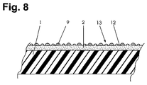
FIG. 8 illustrates a cross-section of a second variant for the process step according to FIG. 6.
DETAILED DESCRIPTION OF THE INVENTION
Reference is now made in detail to exemplary embodiments of the present invention illustrated in the accompanying drawings. Wherever possible, the same reference numerals are used throughout the drawings to refer to the same or similar parts.
FIG. 1 shows a membrane as an envelope of a pneumatic structure, the airtight membrane is designated by the reference numeral 1. The membrane 1 can be, for example, fabric made of polyester, nylon, fiberglass, aramides coated with a plastic such as PVC, PU, silicone or Teflon® but also flexible films made of such materials if the tensile stresses which occur are within permissible material properties.
A thin layer 2 of a plastic containing a plurality of small gas bubbles 3 is applied to the inside of this membrane 1 by means of one of the known techniques, i.e., for example, by wiping, rolling or spraying. Polyurethane, for example, is used as the plastic here.
For example, PVC-coated polyester fabric from Duraskin® (Type III, Verseldag, Krefeld) was coated with different commercially available closed-pore polyurethane foams according to the manufacturer's instructions. The two-component polyurethane foam Polyfoam F5 (Polyconform GmbH) proved to be particularly suitable here.
The aforementioned gas bubbles 3 located in the plastic of the layer 2 can either be incorporated therein by a rapid mixing process of the plastic. However, they can also be formed by the polymerization process and then left in the plastic by omitting a vacuum treatment. Gas bubbles in the range of 10μ-200μ have proved successful for the desired self-healing process of an injury to the membrane 1. (An arrangement comprising a stereomicroscope (Olympus, SZX9) and connected digital camera (Olympus DP12, Japan) was advantageous for studying the membrane 1 coated by the layer 2).
The membrane 1 was then polymerized at elevated pressure. However, the polymerization parameters such as pressure and temperature can vary, being specific to the plastic. The elevated pressure, typically 2 bar, is important.
An excess pressure over 5 bar leads to a deterioration in the self-healing or repair capability compared with an excess pressure of 2 bar, which lies in the range which is already attainable during polymerization without excess pressure. As has been mentioned, the best self-healing results were achieved during polymerization at an excess pressure in the range of 2 bar. Polymerization in an excess pressure range of 2 to 3 bar also yielded good results. Polymerization in the excess pressure range of 0.5 to 4 bar still yields significantly better results compared with polymerization without excess pressure.
The improved reaction properties can be attributed to the elevated internal pressure of the foam cells or bubbles (3) and also to conformational or structural changes inside the foam which have a positive influence on the repair, i.e. sealing, behavior merely as a result of a different arrangement of the material.
The repair behavior could also be further improved by determining the amount of plastic to be polymerized applied per unit area; better results in the self-healing or repair behavior were achieved with an amount of coating in the range of 1 to 2 g for an area of about 20 cm2 (circular sample having a diameter of 5 cm) as compared with amounts of coating outside this range. A coating amount of 1.6 g proved to be particularly advantageous. This corresponds to a quantity per 100 cm2 of 5 to 10 g or an optimal quantity of 8 g of coating material.
Finally, it has also proved favorable to store the coated membrane after polymerization or protect it from mechanical stressing, i.e. to delay the time before the possible first injury. An improvement in the repair capability of the coated membrane was already observed after a week, with eight weeks having proved to be particularly advantageous.
If the membrane 1 is injured by piercing with a pointed object, a hole thus formed will close partly by itself as a result of the elastic properties of the membrane 1 as shown in FIG. 2. A fissure 5 as shown in FIG. 3 remains.
FIG. 4 shows a section of the uppermost part of the fissure 5. Under the influence of the internal pressure of the gas bubbles or an internal stress of the layer 2, a part of the layer 2 is pushed into the fissure 5 and is partially pressed therein by the escaping air; a process which can take seconds to minutes. The cross-section of the hole is thereby reduced and the leakage flow severely suppressed. Since the internal pressure can usually be maintained by external means such as compressors or, at low internal pressures of pneumatic structures, by fans, and in addition, this internal pressure is usually permanently monitored, there is sufficient time for an intervention in the sense of a repair to the envelope of the pneumatic structure.
For fissures 5 of small diameter, complete closure can occur merely as a result of the subsequent pushing of the layer 2.
In the case of larger holes 4 or holes caused by blunt objects or by projectiles from firearms, however, the self-healing effect described with reference to FIGS. 2 to 4 does not result in complete closure of the hole 4. With such an injury, the layer 2 is torn along a larger rim of a hole. In order to make self-healing possible even in said cases, pre-polymers in a suitable form, for example, are provided which polymerize on contact with air and the moisture contained therein. Typically, on contact with the moisture in the air, such polymers form bubbles which are drawn into the hole 4 and completely cure there. Moreover, since the structural forces are absorbed by the membrane, a hole in the membrane is not a weakening if the force flow is interrupted as a result of the lower strength of its filling. Alternatively, two-component plastics can also be used in a suitable form instead of pre-polymers.
FIG. 5 shows a first exemplary embodiment of a second step of this production method according to the invention. Here, a plurality of microcapsules 6 are mixed into the material of the layer 2. Such microcapsules typically having a diameter of about 100μ, contain, for example, a monomer, others contain an accelerator and/or a catalyst for effecting the polymerization of the monomer. The monomer can also contain a solvent in which a suitable gas is dissolved under pressure. Such techniques are known from plastics technology. In addition, such microcapsules 6 can also contain a pre-polymer which preferably contains a solvent and a propellant gas dissolved therein under pressure. If such microcapsules 6 are torn by an injury, a puncture or a penetration wound, the contents of a plurality of microcapsules 6 escape at the rim of the hole, forming a foam 7 which now hardens under the influence of the catalysts or the air humidity and permanently closes the hole 4. In the case of textile-reinforced membranes 1, adhesion to the walls of the hole 4 also occurs if the plastic contained in the microcapsules 6 does not bind sealingly or only poorly binds to that of the layer 2 or that of the membrane 1 since a plurality of textile fibers are exposed and the plastic emerging from the microcapsules can adhere to their open ends. Otherwise, the plastic of the membrane coating must be matched to that of the layer 2. Naturally and optimally, said plastics are matched to one another, and the sealing can thus be optimized.
FIG. 6 shows a plan view of a blister film 8 which either contains a monomer or, in a selected distribution, a monomer and a suitable polymerization partner or a moisture-curing pre-polymer with accelerator, in a plurality of blisters 9. The size of the blisters 9 can be selected and adapted in a broad framework so that, in conjunction with the distances a between the blisters 9, this ensures that in the event of injuries to the membrane which go beyond the self-healing capability of the layer 7, a plurality of such blisters 6 are torn. A foam then forms, as described for FIG. 5, which enters into the injury and polymerizes there. A distance d>a is provided between the rows of blisters 9 at said distances a, which allows the blister film to be fastened to the layer 2 by gluing or welding.
Naturally, the blisters 9 can be produced in any suitable shape and the surface coverage thereby optimized. The size of the blisters 9 can also be varied widely.
FIG. 7 shows a variant of the exemplary embodiment from, also in plan view. Here, elongated blisters 10 are provided, for example, filled with a monomer. In a second position, on the back of the blister film 8, other blisters 11 are arranged coincidentally (shown with dotted rims). Naturally, the shapes can also be selected differently here and the respective size ratios of the blisters 10, 122 can be provided differently. It corresponds to the inventive idea to arrange the blisters 10, 11 such that if a blister 10 is injured, a blister 11 is also injured so that a polymerizing plastic is formed and can penetrate into a hole 4 and seal this. In this exemplary embodiment a strip d>a can also be provided to allow the blister film 8 to be glued or welded to the layer 2, without injuring the blisters 10, 11.
An alternative to the method examples in FIGS. 6 and 7 is shown in FIG. 8. Before the layer 2 is pressure-polymerised, a blister film 12 is applied thereto which, compared to the blister films 8 already described, additionally has a perforation extending into the surface, consisting of a plurality of small holes 13 which preferably have a diameter of 0.1 to 1.0 mm. The blisters 9 again, for example, contain two components of a suitable plastic.
After applying the blister film 12, the polymerisation now takes place under pressure, as described for FIG. 1. The blister film 12 is fixed on the layer 2 by partial penetration of the layer 2 into the perforation.
Although various embodiments of the method and apparatus of the present invention have been illustrated in the accompanying Drawings and described in the foregoing Detailed Description, it will be understood that the invention is not limited to the embodiments disclosed, but is capable of numerous rearrangements, modifications, and substitutions without departing from the spirit and scope of the invention as set forth in the foregoing specification and following claims.

Claims (15)

The invention claimed is:
1. A method of producing a self-healing membrane of a type for compressed-gastight sealing of a pressurized pneumatic structure having an excess pressure in an order of 10 to 500 mbar, the method comprising:
applying a layer of a polymerizable plastic to an interior side of an envelope, the envelope comprising a gastight membrane, and containing a compressed gas;
polymerizing the layer of polymerizable plastic under pressure, the polymerizing forming a plurality of air or gas bubbles in the layer of polymerizable plastic; and
wherein air or gas bubbles, suspended in the layer of polymerizable plastic, and formed by the polymerizing step, are not removed by a vacuum treatment.
2. The method according to claim 1, wherein the self-healing membrane is reinforced with a textile fabric and is made gastight by means of a plastic coating.
3. The method according to claim 1, wherein a plurality of microcapsules are added to the layer of polymerizable plastic before the step of polymerizing.
4. The method according to claim 3, wherein the plurality of microcapsules comprise a moisture-curing pre-polymer.
5. The method according to claim 3, further comprising:
a first plurality of microcapsules comprising a monomer;
a second plurality of microcapsules comprising an accelerator and/or a catalyst; and
wherein a ratio of the first plurality of microcapsules to the second plurality of microcapsules are disposed with the plastic to be polymerized.
6. The method according to claim 1, wherein prior to the step of polymerizing, a blister film is applied to the layer of polymerizable plastic, said blister film comprising:
a plurality of small holes disposed on a side facing away from the layer of polymerizable plastic;
a plurality of blisters, comprising:
a first number of blisters comprising a monomer;
a second number of blisters comprising an accelerator and/or a catalyst; and
wherein a ratio of the first number of blisters to the second number of blisters are disposed with the plastic to be polymerized.
7. The method according to claim 3, wherein a blister film, comprising a plurality of blisters, is glued or welded to the layer of polymerizable plastic, the blisters having a uniform distance from one another.
8. The method according to claim 7, wherein the plurality of blisters contain a moisture-curing pre-polymer.
9. The method according to claim 7, wherein the blister film comprises:
a first plurality of blisters containing a first component of a two-component plastic;
a second plurality of blisters containing a second component of the two-component plastic; and
wherein the first plurality of blisters and the second plurality of blisters are arranged alternately on the blister film.
10. The method according to claim 7, wherein:
the blister film comprises a first plurality of blisters and a second plurality of blisters disposed on opposite sides of a central film;
the first plurality of blisters comprise a monomer, the second plurality of blisters comprise a second component of a two-component plastic; and
the first and second plurality of blisters are arranged at least partly coincidentally.
11. The method according to claim 10, wherein the first plurality of blisters are elongated and the second plurality of blisters are generally circular.
12. The method according to claim 7, wherein, the plurality of blisters are arranged in rows, the rows having variable spacing with respect to each other.
13. The method according to claim 1, wherein the step of polymerizing takes place at an excess pressure of approximately 0.4 to approximately 4 bar.
14. The method according to claim 1, wherein the layer of polymerizable plastic is applied to the membrane in an amount of approximately 5 to approximately 10 g per 100 cm2 of membrane surface.
15. The method according to claim 1, further comprising the step of storing a coated membrane over a period of approximately 1 to approximately 8 weeks.
US11/922,859 2005-07-15 2006-07-12 Method of producing a self-healing membrane Expired - Fee Related US8822024B2 (en)

Applications Claiming Priority (3)

Application Number Priority Date Filing Date Title
CH11792005 2005-07-15
CH1179/05 2005-07-15
PCT/CH2006/000366 WO2007009280A1 (en) 2005-07-15 2006-07-12 Self-healing membrane

Publications (2)

Publication Number Publication Date
US20090035551A1 US20090035551A1 (en) 2009-02-05
US8822024B2 true US8822024B2 (en) 2014-09-02

Family

ID=35965989

Family Applications (1)

Application Number Title Priority Date Filing Date
US11/922,859 Expired - Fee Related US8822024B2 (en) 2005-07-15 2006-07-12 Method of producing a self-healing membrane

Country Status (3)

Country Link
US (1) US8822024B2 (en)
EP (1) EP1904291A1 (en)
WO (1) WO2007009280A1 (en)

Cited By (1)

* Cited by examiner, † Cited by third party
Publication number Priority date Publication date Assignee Title
US20160325417A1 (en) * 2015-04-16 2016-11-10 Thomas L. Klamm Oil filter removal tool

Families Citing this family (10)

* Cited by examiner, † Cited by third party
Publication number Priority date Publication date Assignee Title
US7566747B2 (en) 2004-05-07 2009-07-28 The Board Of Trustees Of The University Of Illinois Wax particles for protection of activators, and multifunctional autonomically healing composite materials
US7612152B2 (en) 2005-05-06 2009-11-03 The Board Of Trustees Of The University Of Illinois Self-healing polymers
US7723405B2 (en) 2006-01-05 2010-05-25 The Board Of Trustees Of The University Of Illinois Self-healing coating system
US7569625B2 (en) 2006-06-02 2009-08-04 The Board Of Trustees Of The University Of Illinois Self-healing elastomer system
US9415575B2 (en) 2008-01-25 2016-08-16 The Board Of Trustees Of The University Of Illinois Self-healing laminate system
WO2011097298A1 (en) * 2010-02-02 2011-08-11 Abinito Vsd Llc Bag vacuum apparatus
US9605162B2 (en) 2013-03-15 2017-03-28 Honda Motor Co., Ltd. Corrosion inhibiting compositions and methods of making and using
US9816189B2 (en) 2013-03-15 2017-11-14 Honda Motor Co., Ltd. Corrosion inhibiting compositions and coatings including the same
US10384167B2 (en) 2013-11-21 2019-08-20 Oasys Water LLC Systems and methods for improving performance of osmotically driven membrane systems
DE102019210086A1 (en) * 2019-07-09 2021-01-14 Castrol Limited Fluid cell for filtering a fluid

Citations (11)

* Cited by examiner, † Cited by third party
Publication number Priority date Publication date Assignee Title
US1959460A (en) 1930-07-11 1934-05-22 Jesse R Crossan Method of producing punctureproof tire tubes
US3444918A (en) 1967-04-24 1969-05-20 True Car Value Inc Self-sealing safety tire
EP0370039A1 (en) 1987-08-06 1990-05-30 Ludwig Resch Process and device for doffing yarn bobbins.
US5350481A (en) 1993-08-10 1994-09-27 Shepard Steven M Repair device for elastomeric wall
EP0764875A1 (en) 1995-09-21 1997-03-26 Kabushiki Kaisha Toshiba Multiscreen displaying apparatus and screen fitting structure
EP1210489A1 (en) 2000-03-27 2002-06-05 Mauro Pedretti Pneumatic structural element
EP1239756A2 (en) 2000-11-29 2002-09-18 Prospective Concepts AG Pneumatic mattress
WO2004007608A2 (en) 2002-07-15 2004-01-22 Motorola, Inc. Self-healing polymer compositions
WO2004009400A1 (en) 2002-07-18 2004-01-29 Prospective Concepts Ag Adaptive pneumatic sitting and reclining cushion for vehicles and aircraft
WO2005007991A1 (en) 2003-07-18 2005-01-27 Prospective Concepts Ag Pneumatic support
EP1554158A1 (en) 2002-07-18 2005-07-20 Prospective Concepts AG Adaptive pneumatic seat and backrest cushions for vehicles and airplanes

Family Cites Families (2)

* Cited by examiner, † Cited by third party
Publication number Priority date Publication date Assignee Title
US4282052A (en) * 1979-03-19 1981-08-04 The Goodyear Tire & Rubber Company Method of preparing a self-sealing pneumatic tire
EP1484199B1 (en) * 2002-03-08 2008-08-06 The Yokohama Rubber Co., Ltd. Method of manufacturing a self-sealing tire

Patent Citations (11)

* Cited by examiner, † Cited by third party
Publication number Priority date Publication date Assignee Title
US1959460A (en) 1930-07-11 1934-05-22 Jesse R Crossan Method of producing punctureproof tire tubes
US3444918A (en) 1967-04-24 1969-05-20 True Car Value Inc Self-sealing safety tire
EP0370039A1 (en) 1987-08-06 1990-05-30 Ludwig Resch Process and device for doffing yarn bobbins.
US5350481A (en) 1993-08-10 1994-09-27 Shepard Steven M Repair device for elastomeric wall
EP0764875A1 (en) 1995-09-21 1997-03-26 Kabushiki Kaisha Toshiba Multiscreen displaying apparatus and screen fitting structure
EP1210489A1 (en) 2000-03-27 2002-06-05 Mauro Pedretti Pneumatic structural element
EP1239756A2 (en) 2000-11-29 2002-09-18 Prospective Concepts AG Pneumatic mattress
WO2004007608A2 (en) 2002-07-15 2004-01-22 Motorola, Inc. Self-healing polymer compositions
WO2004009400A1 (en) 2002-07-18 2004-01-29 Prospective Concepts Ag Adaptive pneumatic sitting and reclining cushion for vehicles and aircraft
EP1554158A1 (en) 2002-07-18 2005-07-20 Prospective Concepts AG Adaptive pneumatic seat and backrest cushions for vehicles and airplanes
WO2005007991A1 (en) 2003-07-18 2005-01-27 Prospective Concepts Ag Pneumatic support

Non-Patent Citations (1)

* Cited by examiner, † Cited by third party
Title
Boone, John ., "International Search Report" for PCT/CH2006/000366 as mailed Nov. 15, 2006, (4 pages).

Cited By (1)

* Cited by examiner, † Cited by third party
Publication number Priority date Publication date Assignee Title
US20160325417A1 (en) * 2015-04-16 2016-11-10 Thomas L. Klamm Oil filter removal tool

Also Published As

Publication number Publication date
WO2007009280A1 (en) 2007-01-25
US20090035551A1 (en) 2009-02-05
EP1904291A1 (en) 2008-04-02

Similar Documents

Publication Publication Date Title
US8822024B2 (en) Method of producing a self-healing membrane
US3675377A (en) Inflatable-deflatable flexible structural component
US11065953B1 (en) Method and system for forming a self-sealing volume using a breather system
Beiermann et al. Self-healing flexible laminates for resealing of puncture damage
US20070059466A1 (en) Medical balloon
JP2008540170A (en) Vacuum bag forming method and system
EP2195158A1 (en) Composite laminated product
JP2010500113A (en) Expandable absorbent polymer device
WO2002098711A1 (en) Airbag having reinforced seams
USRE31898E (en) Inflatable-deflatable flexible structural component
US10549470B1 (en) Method and system for forming a self-sealing volume
US20100209672A1 (en) Metallic Layer Membrane
US8273427B1 (en) Composite material and support structure
US20230339153A1 (en) Foam envelope for sealing large volumes
US5879498A (en) Method of lining fluid vessels
JPH06305089A (en) Production of base fabric for air bag
US20110041475A1 (en) Elastomer structures, rocket motors including elastomer structures and methods of forming structures from layered viscoelastic materials
US7682478B1 (en) Vacuum infusion laminate adhesive
US10301073B1 (en) Robust soft textile transfer case for contaminated materials
CN106189794B (en) Has the tire and preparation method thereof of polyurethane elastomer material in a kind of
EP2217485B1 (en) A structural beam for a vehicle and a method of forming a structural beam for a vehicle
US11814110B2 (en) System for insulating a structural element
JP2017105959A (en) Film for packaging material
US20220153422A1 (en) Evacuation inflatable having self-healing fabric
WO2008073098A1 (en) Improved run-flat tire

Legal Events

Date Code Title Description
AS Assignment

Owner name: PROSPECTIVE CONCEPTS AG, SWITZERLAND

Free format text: ASSIGNMENT OF ASSIGNORS INTEREST;ASSIGNORS:LUCHSINGER, ROLF;SPECK, THOMAS;SPECK, OLGA;REEL/FRAME:020573/0082;SIGNING DATES FROM 20080120 TO 20080128

Owner name: PROSPECTIVE CONCEPTS AG, SWITZERLAND

Free format text: ASSIGNMENT OF ASSIGNORS INTEREST;ASSIGNORS:LUCHSINGER, ROLF;SPECK, THOMAS;SPECK, OLGA;SIGNING DATES FROM 20080120 TO 20080128;REEL/FRAME:020573/0082

FEPP Fee payment procedure

Free format text: PAYOR NUMBER ASSIGNED (ORIGINAL EVENT CODE: ASPN); ENTITY STATUS OF PATENT OWNER: LARGE ENTITY

FEPP Fee payment procedure

Free format text: MAINTENANCE FEE REMINDER MAILED (ORIGINAL EVENT CODE: REM.)

LAPS Lapse for failure to pay maintenance fees

Free format text: PATENT EXPIRED FOR FAILURE TO PAY MAINTENANCE FEES (ORIGINAL EVENT CODE: EXP.); ENTITY STATUS OF PATENT OWNER: LARGE ENTITY

STCH Information on status: patent discontinuation

Free format text: PATENT EXPIRED DUE TO NONPAYMENT OF MAINTENANCE FEES UNDER 37 CFR 1.362

FP Lapsed due to failure to pay maintenance fee

Effective date: 20180902