US8821434B2 - Delivery of a solid body and/or a fluid using a linear Lorentz-force actuated needle-free jet injection system - Google Patents
Delivery of a solid body and/or a fluid using a linear Lorentz-force actuated needle-free jet injection system Download PDFInfo
- Publication number
- US8821434B2 US8821434B2 US13/269,322 US201113269322A US8821434B2 US 8821434 B2 US8821434 B2 US 8821434B2 US 201113269322 A US201113269322 A US 201113269322A US 8821434 B2 US8821434 B2 US 8821434B2
- Authority
- US
- United States
- Prior art keywords
- solid body
- reservoir
- cartridge
- mechanical force
- body includes
- Prior art date
- Legal status (The legal status is an assumption and is not a legal conclusion. Google has not performed a legal analysis and makes no representation as to the accuracy of the status listed.)
- Active, expires
Links
- 239000007787 solid Substances 0.000 title claims abstract description 52
- 239000012530 fluid Substances 0.000 title claims abstract description 24
- 238000002347 injection Methods 0.000 title description 46
- 239000007924 injection Substances 0.000 title description 46
- 238000000034 method Methods 0.000 claims abstract description 27
- 239000003814 drug Substances 0.000 claims description 29
- 229940079593 drug Drugs 0.000 claims description 27
- 239000002775 capsule Substances 0.000 claims description 8
- 239000007943 implant Substances 0.000 claims description 8
- 239000011859 microparticle Substances 0.000 claims description 4
- 238000004891 communication Methods 0.000 claims description 2
- 238000007789 sealing Methods 0.000 claims 2
- 239000000126 substance Substances 0.000 abstract description 32
- 238000010408 sweeping Methods 0.000 abstract description 5
- 210000001519 tissue Anatomy 0.000 description 29
- 238000012546 transfer Methods 0.000 description 25
- 229940090046 jet injector Drugs 0.000 description 15
- 239000000463 material Substances 0.000 description 12
- 239000003708 ampul Substances 0.000 description 11
- 230000005291 magnetic effect Effects 0.000 description 11
- 239000002245 particle Substances 0.000 description 11
- 230000033001 locomotion Effects 0.000 description 9
- 238000009472 formulation Methods 0.000 description 8
- 239000000203 mixture Substances 0.000 description 8
- 239000010410 layer Substances 0.000 description 7
- 229960005486 vaccine Drugs 0.000 description 7
- 239000011324 bead Substances 0.000 description 6
- 238000006073 displacement reaction Methods 0.000 description 6
- NOESYZHRGYRDHS-UHFFFAOYSA-N insulin Chemical compound N1C(=O)C(NC(=O)C(CCC(N)=O)NC(=O)C(CCC(O)=O)NC(=O)C(C(C)C)NC(=O)C(NC(=O)CN)C(C)CC)CSSCC(C(NC(CO)C(=O)NC(CC(C)C)C(=O)NC(CC=2C=CC(O)=CC=2)C(=O)NC(CCC(N)=O)C(=O)NC(CC(C)C)C(=O)NC(CCC(O)=O)C(=O)NC(CC(N)=O)C(=O)NC(CC=2C=CC(O)=CC=2)C(=O)NC(CSSCC(NC(=O)C(C(C)C)NC(=O)C(CC(C)C)NC(=O)C(CC=2C=CC(O)=CC=2)NC(=O)C(CC(C)C)NC(=O)C(C)NC(=O)C(CCC(O)=O)NC(=O)C(C(C)C)NC(=O)C(CC(C)C)NC(=O)C(CC=2NC=NC=2)NC(=O)C(CO)NC(=O)CNC2=O)C(=O)NCC(=O)NC(CCC(O)=O)C(=O)NC(CCCNC(N)=N)C(=O)NCC(=O)NC(CC=3C=CC=CC=3)C(=O)NC(CC=3C=CC=CC=3)C(=O)NC(CC=3C=CC(O)=CC=3)C(=O)NC(C(C)O)C(=O)N3C(CCC3)C(=O)NC(CCCCN)C(=O)NC(C)C(O)=O)C(=O)NC(CC(N)=O)C(O)=O)=O)NC(=O)C(C(C)CC)NC(=O)C(CO)NC(=O)C(C(C)O)NC(=O)C1CSSCC2NC(=O)C(CC(C)C)NC(=O)C(NC(=O)C(CCC(N)=O)NC(=O)C(CC(N)=O)NC(=O)C(NC(=O)C(N)CC=1C=CC=CC=1)C(C)C)CC1=CN=CN1 NOESYZHRGYRDHS-UHFFFAOYSA-N 0.000 description 6
- 230000035515 penetration Effects 0.000 description 6
- RYGMFSIKBFXOCR-UHFFFAOYSA-N Copper Chemical compound [Cu] RYGMFSIKBFXOCR-UHFFFAOYSA-N 0.000 description 5
- 238000010586 diagram Methods 0.000 description 5
- XLYOFNOQVPJJNP-UHFFFAOYSA-N water Substances O XLYOFNOQVPJJNP-UHFFFAOYSA-N 0.000 description 5
- 229910000975 Carbon steel Inorganic materials 0.000 description 4
- 241001465754 Metazoa Species 0.000 description 4
- 239000010962 carbon steel Substances 0.000 description 4
- 238000013270 controlled release Methods 0.000 description 4
- 230000003993 interaction Effects 0.000 description 4
- 229910052751 metal Inorganic materials 0.000 description 4
- 239000002184 metal Substances 0.000 description 4
- 230000000704 physical effect Effects 0.000 description 4
- 102000004877 Insulin Human genes 0.000 description 3
- 108090001061 Insulin Proteins 0.000 description 3
- 206010052428 Wound Diseases 0.000 description 3
- 208000027418 Wounds and injury Diseases 0.000 description 3
- 230000008859 change Effects 0.000 description 3
- 238000013461 design Methods 0.000 description 3
- 238000011161 development Methods 0.000 description 3
- 230000018109 developmental process Effects 0.000 description 3
- 238000005516 engineering process Methods 0.000 description 3
- 239000003302 ferromagnetic material Substances 0.000 description 3
- 230000006870 function Effects 0.000 description 3
- 229940125396 insulin Drugs 0.000 description 3
- 229910001172 neodymium magnet Inorganic materials 0.000 description 3
- 229920000642 polymer Polymers 0.000 description 3
- 239000010935 stainless steel Substances 0.000 description 3
- 229910001220 stainless steel Inorganic materials 0.000 description 3
- XEEYBQQBJWHFJM-UHFFFAOYSA-N Iron Chemical compound [Fe] XEEYBQQBJWHFJM-UHFFFAOYSA-N 0.000 description 2
- 239000004793 Polystyrene Substances 0.000 description 2
- 229910000831 Steel Inorganic materials 0.000 description 2
- 230000008901 benefit Effects 0.000 description 2
- 239000004020 conductor Substances 0.000 description 2
- 238000012377 drug delivery Methods 0.000 description 2
- 230000000694 effects Effects 0.000 description 2
- 238000001125 extrusion Methods 0.000 description 2
- 239000007789 gas Substances 0.000 description 2
- PCHJSUWPFVWCPO-UHFFFAOYSA-N gold Chemical compound [Au] PCHJSUWPFVWCPO-UHFFFAOYSA-N 0.000 description 2
- 239000010931 gold Substances 0.000 description 2
- 229910052737 gold Inorganic materials 0.000 description 2
- 230000001976 improved effect Effects 0.000 description 2
- 230000006872 improvement Effects 0.000 description 2
- 239000007788 liquid Substances 0.000 description 2
- 230000003287 optical effect Effects 0.000 description 2
- 239000004417 polycarbonate Substances 0.000 description 2
- 229920002223 polystyrene Polymers 0.000 description 2
- 238000012545 processing Methods 0.000 description 2
- 230000001737 promoting effect Effects 0.000 description 2
- 102000004169 proteins and genes Human genes 0.000 description 2
- 108090000623 proteins and genes Proteins 0.000 description 2
- 230000004044 response Effects 0.000 description 2
- 238000005070 sampling Methods 0.000 description 2
- 239000010959 steel Substances 0.000 description 2
- 235000000346 sugar Nutrition 0.000 description 2
- 150000008163 sugars Chemical class 0.000 description 2
- 230000008685 targeting Effects 0.000 description 2
- 230000001225 therapeutic effect Effects 0.000 description 2
- HDTRYLNUVZCQOY-UHFFFAOYSA-N α-D-glucopyranosyl-α-D-glucopyranoside Natural products OC1C(O)C(O)C(CO)OC1OC1C(O)C(O)C(O)C(CO)O1 HDTRYLNUVZCQOY-UHFFFAOYSA-N 0.000 description 1
- HRPVXLWXLXDGHG-UHFFFAOYSA-N Acrylamide Chemical compound NC(=O)C=C HRPVXLWXLXDGHG-UHFFFAOYSA-N 0.000 description 1
- 102000002265 Human Growth Hormone Human genes 0.000 description 1
- 108010000521 Human Growth Hormone Proteins 0.000 description 1
- 239000000854 Human Growth Hormone Substances 0.000 description 1
- NNJVILVZKWQKPM-UHFFFAOYSA-N Lidocaine Chemical compound CCN(CC)CC(=O)NC1=C(C)C=CC=C1C NNJVILVZKWQKPM-UHFFFAOYSA-N 0.000 description 1
- 208000012266 Needlestick injury Diseases 0.000 description 1
- 229930182556 Polyacetal Natural products 0.000 description 1
- 239000004697 Polyetherimide Substances 0.000 description 1
- 229920000954 Polyglycolide Polymers 0.000 description 1
- 206010037742 Rabies Diseases 0.000 description 1
- CZMRCDWAGMRECN-UGDNZRGBSA-N Sucrose Chemical compound O[C@H]1[C@H](O)[C@@H](CO)O[C@@]1(CO)O[C@@H]1[C@H](O)[C@@H](O)[C@H](O)[C@@H](CO)O1 CZMRCDWAGMRECN-UGDNZRGBSA-N 0.000 description 1
- 229930006000 Sucrose Natural products 0.000 description 1
- 229920001070 Techron Polymers 0.000 description 1
- 206010043376 Tetanus Diseases 0.000 description 1
- HDTRYLNUVZCQOY-WSWWMNSNSA-N Trehalose Natural products O[C@@H]1[C@@H](O)[C@@H](O)[C@@H](CO)O[C@@H]1O[C@@H]1[C@H](O)[C@@H](O)[C@@H](O)[C@@H](CO)O1 HDTRYLNUVZCQOY-WSWWMNSNSA-N 0.000 description 1
- QJVKUMXDEUEQLH-UHFFFAOYSA-N [B].[Fe].[Nd] Chemical compound [B].[Fe].[Nd] QJVKUMXDEUEQLH-UHFFFAOYSA-N 0.000 description 1
- 239000011354 acetal resin Substances 0.000 description 1
- 230000004913 activation Effects 0.000 description 1
- 229910045601 alloy Inorganic materials 0.000 description 1
- 239000000956 alloy Substances 0.000 description 1
- HDTRYLNUVZCQOY-LIZSDCNHSA-N alpha,alpha-trehalose Chemical compound O[C@@H]1[C@@H](O)[C@H](O)[C@@H](CO)O[C@@H]1O[C@@H]1[C@H](O)[C@@H](O)[C@H](O)[C@@H](CO)O1 HDTRYLNUVZCQOY-LIZSDCNHSA-N 0.000 description 1
- 238000013459 approach Methods 0.000 description 1
- 230000004323 axial length Effects 0.000 description 1
- 230000002457 bidirectional effect Effects 0.000 description 1
- 229920002988 biodegradable polymer Polymers 0.000 description 1
- 239000004621 biodegradable polymer Substances 0.000 description 1
- 229960000074 biopharmaceutical Drugs 0.000 description 1
- 230000015572 biosynthetic process Effects 0.000 description 1
- 210000004369 blood Anatomy 0.000 description 1
- 239000008280 blood Substances 0.000 description 1
- 210000004556 brain Anatomy 0.000 description 1
- 210000004027 cell Anatomy 0.000 description 1
- 238000011109 contamination Methods 0.000 description 1
- 229920001577 copolymer Polymers 0.000 description 1
- 229910052802 copper Inorganic materials 0.000 description 1
- 239000010949 copper Substances 0.000 description 1
- 239000002537 cosmetic Substances 0.000 description 1
- 238000013016 damping Methods 0.000 description 1
- 230000001419 dependent effect Effects 0.000 description 1
- 239000013583 drug formulation Substances 0.000 description 1
- 238000011156 evaluation Methods 0.000 description 1
- 210000003722 extracellular fluid Anatomy 0.000 description 1
- 230000004907 flux Effects 0.000 description 1
- 238000007496 glass forming Methods 0.000 description 1
- 239000000017 hydrogel Substances 0.000 description 1
- 238000003384 imaging method Methods 0.000 description 1
- 239000012729 immediate-release (IR) formulation Substances 0.000 description 1
- 238000002649 immunization Methods 0.000 description 1
- 230000003053 immunization Effects 0.000 description 1
- 238000002513 implantation Methods 0.000 description 1
- 230000006698 induction Effects 0.000 description 1
- 230000001939 inductive effect Effects 0.000 description 1
- 206010022000 influenza Diseases 0.000 description 1
- 230000000977 initiatory effect Effects 0.000 description 1
- 229910052742 iron Inorganic materials 0.000 description 1
- 229960004194 lidocaine Drugs 0.000 description 1
- 239000002502 liposome Substances 0.000 description 1
- 239000012669 liquid formulation Substances 0.000 description 1
- 230000014759 maintenance of location Effects 0.000 description 1
- 230000004048 modification Effects 0.000 description 1
- 238000012986 modification Methods 0.000 description 1
- 238000012544 monitoring process Methods 0.000 description 1
- 239000002105 nanoparticle Substances 0.000 description 1
- 230000001537 neural effect Effects 0.000 description 1
- 239000002547 new drug Substances 0.000 description 1
- 238000004806 packaging method and process Methods 0.000 description 1
- 239000000546 pharmaceutical excipient Substances 0.000 description 1
- 239000004033 plastic Substances 0.000 description 1
- 229920003023 plastic Polymers 0.000 description 1
- 229920000747 poly(lactic acid) Polymers 0.000 description 1
- 229920000515 polycarbonate Polymers 0.000 description 1
- 229920001601 polyetherimide Polymers 0.000 description 1
- 229920006324 polyoxymethylene Polymers 0.000 description 1
- 239000000843 powder Substances 0.000 description 1
- -1 powdered vaccines Substances 0.000 description 1
- 238000002360 preparation method Methods 0.000 description 1
- 230000008569 process Effects 0.000 description 1
- 230000002035 prolonged effect Effects 0.000 description 1
- 229910052761 rare earth metal Inorganic materials 0.000 description 1
- 150000002910 rare earth metals Chemical class 0.000 description 1
- 230000002441 reversible effect Effects 0.000 description 1
- 238000007493 shaping process Methods 0.000 description 1
- 238000010008 shearing Methods 0.000 description 1
- 239000000243 solution Substances 0.000 description 1
- 239000005720 sucrose Substances 0.000 description 1
- 239000002344 surface layer Substances 0.000 description 1
- 238000004381 surface treatment Methods 0.000 description 1
- 238000012360 testing method Methods 0.000 description 1
- 238000013334 tissue model Methods 0.000 description 1
- 230000007704 transition Effects 0.000 description 1
- 238000004804 winding Methods 0.000 description 1
- 229910000859 α-Fe Inorganic materials 0.000 description 1
Images


Classifications
-
- A—HUMAN NECESSITIES
- A61—MEDICAL OR VETERINARY SCIENCE; HYGIENE
- A61M—DEVICES FOR INTRODUCING MEDIA INTO, OR ONTO, THE BODY; DEVICES FOR TRANSDUCING BODY MEDIA OR FOR TAKING MEDIA FROM THE BODY; DEVICES FOR PRODUCING OR ENDING SLEEP OR STUPOR
- A61M5/00—Devices for bringing media into the body in a subcutaneous, intra-vascular or intramuscular way; Accessories therefor, e.g. filling or cleaning devices, arm-rests
- A61M5/178—Syringes
- A61M5/30—Syringes for injection by jet action, without needle, e.g. for use with replaceable ampoules or carpules
- A61M5/3015—Syringes for injection by jet action, without needle, e.g. for use with replaceable ampoules or carpules for injecting a dose of particles in form of powdered drug, e.g. mounted on a rupturable membrane and accelerated by a gaseous shock wave or supersonic gas flow
-
- A—HUMAN NECESSITIES
- A61—MEDICAL OR VETERINARY SCIENCE; HYGIENE
- A61M—DEVICES FOR INTRODUCING MEDIA INTO, OR ONTO, THE BODY; DEVICES FOR TRANSDUCING BODY MEDIA OR FOR TAKING MEDIA FROM THE BODY; DEVICES FOR PRODUCING OR ENDING SLEEP OR STUPOR
- A61M2205/00—General characteristics of the apparatus
- A61M2205/33—Controlling, regulating or measuring
- A61M2205/332—Force measuring means
-
- A—HUMAN NECESSITIES
- A61—MEDICAL OR VETERINARY SCIENCE; HYGIENE
- A61M—DEVICES FOR INTRODUCING MEDIA INTO, OR ONTO, THE BODY; DEVICES FOR TRANSDUCING BODY MEDIA OR FOR TAKING MEDIA FROM THE BODY; DEVICES FOR PRODUCING OR ENDING SLEEP OR STUPOR
- A61M2205/00—General characteristics of the apparatus
- A61M2205/33—Controlling, regulating or measuring
- A61M2205/3331—Pressure; Flow
-
- A—HUMAN NECESSITIES
- A61—MEDICAL OR VETERINARY SCIENCE; HYGIENE
- A61M—DEVICES FOR INTRODUCING MEDIA INTO, OR ONTO, THE BODY; DEVICES FOR TRANSDUCING BODY MEDIA OR FOR TAKING MEDIA FROM THE BODY; DEVICES FOR PRODUCING OR ENDING SLEEP OR STUPOR
- A61M2205/00—General characteristics of the apparatus
- A61M2205/35—Communication
- A61M2205/3546—Range
- A61M2205/3561—Range local, e.g. within room or hospital
-
- A—HUMAN NECESSITIES
- A61—MEDICAL OR VETERINARY SCIENCE; HYGIENE
- A61M—DEVICES FOR INTRODUCING MEDIA INTO, OR ONTO, THE BODY; DEVICES FOR TRANSDUCING BODY MEDIA OR FOR TAKING MEDIA FROM THE BODY; DEVICES FOR PRODUCING OR ENDING SLEEP OR STUPOR
- A61M2205/00—General characteristics of the apparatus
- A61M2205/35—Communication
- A61M2205/3576—Communication with non implanted data transmission devices, e.g. using external transmitter or receiver
- A61M2205/3584—Communication with non implanted data transmission devices, e.g. using external transmitter or receiver using modem, internet or bluetooth
-
- A—HUMAN NECESSITIES
- A61—MEDICAL OR VETERINARY SCIENCE; HYGIENE
- A61M—DEVICES FOR INTRODUCING MEDIA INTO, OR ONTO, THE BODY; DEVICES FOR TRANSDUCING BODY MEDIA OR FOR TAKING MEDIA FROM THE BODY; DEVICES FOR PRODUCING OR ENDING SLEEP OR STUPOR
- A61M2205/00—General characteristics of the apparatus
- A61M2205/58—Means for facilitating use, e.g. by people with impaired vision
- A61M2205/583—Means for facilitating use, e.g. by people with impaired vision by visual feedback
-
- A—HUMAN NECESSITIES
- A61—MEDICAL OR VETERINARY SCIENCE; HYGIENE
- A61M—DEVICES FOR INTRODUCING MEDIA INTO, OR ONTO, THE BODY; DEVICES FOR TRANSDUCING BODY MEDIA OR FOR TAKING MEDIA FROM THE BODY; DEVICES FOR PRODUCING OR ENDING SLEEP OR STUPOR
- A61M37/00—Other apparatus for introducing media into the body; Percutany, i.e. introducing medicines into the body by diffusion through the skin
- A61M37/0069—Devices for implanting pellets, e.g. markers or solid medicaments
-
- A—HUMAN NECESSITIES
- A61—MEDICAL OR VETERINARY SCIENCE; HYGIENE
- A61M—DEVICES FOR INTRODUCING MEDIA INTO, OR ONTO, THE BODY; DEVICES FOR TRANSDUCING BODY MEDIA OR FOR TAKING MEDIA FROM THE BODY; DEVICES FOR PRODUCING OR ENDING SLEEP OR STUPOR
- A61M5/00—Devices for bringing media into the body in a subcutaneous, intra-vascular or intramuscular way; Accessories therefor, e.g. filling or cleaning devices, arm-rests
- A61M5/178—Syringes
- A61M5/19—Syringes having more than one chamber, e.g. including a manifold coupling two parallelly aligned syringes through separate channels to a common discharge assembly
-
- A—HUMAN NECESSITIES
- A61—MEDICAL OR VETERINARY SCIENCE; HYGIENE
- A61M—DEVICES FOR INTRODUCING MEDIA INTO, OR ONTO, THE BODY; DEVICES FOR TRANSDUCING BODY MEDIA OR FOR TAKING MEDIA FROM THE BODY; DEVICES FOR PRODUCING OR ENDING SLEEP OR STUPOR
- A61M5/00—Devices for bringing media into the body in a subcutaneous, intra-vascular or intramuscular way; Accessories therefor, e.g. filling or cleaning devices, arm-rests
- A61M5/42—Devices for bringing media into the body in a subcutaneous, intra-vascular or intramuscular way; Accessories therefor, e.g. filling or cleaning devices, arm-rests having means for desensitising skin, for protruding skin to facilitate piercing, or for locating point where body is to be pierced
- A61M5/427—Locating point where body is to be pierced, e.g. vein location means using ultrasonic waves, injection site templates
Definitions
- This application relates generally to needle-free transdermal transport devices, particularly to methods of delivering substances, including solid bodies by using needle-free devices.
- Needle-free jet injection provides an equally effective alternate route for the administration of drugs that is free of many of the problems associated with conventional delivery using a needle and syringe (e.g., needle stick injections, expense associated with disposal of sharps, belonephobia, and compliance). Jet injectors can be classified by the actuator used to generate the high pressures required for injection; ranging from 5.5 MPa to ⁇ 30 MPa dependent on the size of the orifice, the desired depth of injection, the viscosity of the drug, and individual skin variation.
- a continuing issue with drug delivery using needle-free jet injectors is repeatable delivery of a specific amount of active drug to the target tissue.
- Commercial devices powered by springs or compressed gases have little to no control over the pressure applied to the drug during the time course of the injection, potentially resulting in shearing and loss of activity of larger therapeutic protein molecules. Furthermore, these devices are often loud and sometimes deemed painful. While some pressure pulse shaping may be afforded by using variable gas orifices and fast/slow pyrotechnic charges, these techniques, while an improvement, may not provide precise control. More recently, Stachowiak et al. developed a jet injector that uses a dynamically controllable piezoelectric stack placed within a mechanical flexure.
- tissue model materials i.e. acrylamide
- penetration depth in tissue model materials may be precisely controlled by adjusting the proportion of the injection volume delivered at high speed.
- the piston stroke and hence the volume of fluid delivered may be limited by the design, which is difficult to scale.
- An electrically driven linear Lorentz-force motor affords robust and precise control over coil position and thereby over both the depth and volume of drug delivered without compromising stroke (e.g., 25 mm in current device) and therefore volume (e.g., 250 ⁇ L in current device).
- stroke e.g. 25 mm in current device
- volume e.g. 250 ⁇ L in current device.
- Energy delivered to the actuator in an electrical form allows one to impose a time varying pressure (or velocity) profile (i.e., waveform) on the drug volume during the course of the injection through the use of a monitored and servo controlled amplifier.
- a time varying pressure (or velocity) profile i.e., waveform
- Controlling the volume of drug delivered ensures that the relevant dose is delivered (e.g., insulin), potentially reduces the dose (e.g., ID delivery of vaccines normally administered intramuscularly [IM] or subcutaneously [SC]) and cost for each deliverable, and increases the availability of drugs in limited supply (e.g., vaccines).
- Controlling the depth of injection ensures delivery to the appropriate tissue layer regardless of body type and enables more accurate delivery of certain drugs that are most effective when delivered SC (e.g., insulin) or IM (e.g., tetanus) or when delivered ID at normal or reduced volume (e.g., lidocaine, TB, rabies, HBV, influenza, etc.).
- jet injectors are used to propel liquid (e.g., insulin, human growth hormone, etc.), reconstituted drug formulations (e.g., vaccines, MAbs), powdered drug, or drug coated particles (e.g., inert gold particles) into the target tissue.
- drug formulations e.g., vaccines, MAbs
- drug coated particles e.g., inert gold particles
- Solid bodies for example polymeric controlled release formulations, powdered vaccines, drug-coated materials etc.
- use of this platform technology for delivery of solids other than biologicals opens a range of possibilities that may include for example delivery of RFID tags for tracking and managing inventory, people, assets etc., delivery of self-assembling scaffolds to build for example circuit boards or cell scaffolds, delivery of metal or coated wires or polymers for use as electrodes, antennae, etc., delivery of sensors, and tattooing for cosmetic, medical, professional, and personal purposes.
- the jet injector may be used to sweep a surface using one or more actuators, thereby allowing movement in multiple directions in one plane and delivery to different depths to create a multi-layered structure that may be a material part (e.g., bar codes etc.) or a structure that may be of potential use in imaging tissue (e.g., different layers within the tissue) and/or other materials.
- a material part e.g., bar codes etc.
- a structure that may be of potential use in imaging tissue e.g., different layers within the tissue
- Embodiments of the invention relate to use of a servo-controlled linear Lorentz-force jet injection technology to deliver one or more solid bodies to a target, for example skin. Delivery may involve using the device configuration as described in A. J. Taberner, N. C. Hogan, and I. W. Hunter, “Real-time feedback-controlled needle-free jet injection using linear Lorentz-force motors,” manuscript submitted to Medical Engineering & Physics August 2011, and A. J. Taberner, N. B. Ball, N. C. Hogan, and I. W. Hunter, A portable needle-free jet injector based on a custom high power-density voice-coil actuator, in Proceedings of the 28 th Annual International Conference of the IEEE Engineering and Medicine and Biology Society , Vol. 1-15 (2006) 2531-2534, both references are incorporated herein by reference in their entireties.
- Delivery may also take place with a modified configuration in which the nozzle has been replaced with a disposable cartridge containing the solid body. Actuation of the coil motor may result in a plunger forcing fluid through either the nozzle orifice or capsule orifice, causing the solid body to be ejected with sufficient force to penetrate the target.
- an embodiment of the invention includes to a method for transferring a solid body across a surface of a biological body.
- the method includes applying an electrical input to a controllable electromagnetic actuator.
- a mechanical force corresponding to the electrical input is produced with the electromagnetic actuator.
- the mechanical force is applied to a reservoir coupled at one end to a nozzle, the mechanical force producing a pressure within the reservoir.
- a magnitude of the pressure varies with the mechanical force and causes ejection of a fluid from the reservoir to drive the solid body into the biological body.
- the solid body Prior to the application of the mechanical force, the solid body may be disposed in the fluid in the reservoir, and the applied force produces a positive pressure ejecting at least a portion of the fluid and the solid body from the reservoir through the nozzle.
- the solid body may be disposed in a cartridge coupled to the nozzle prior to the application of the mechanical force.
- the applied mechanical force may produce a positive pressure to eject at least a portion of the fluid from the reservoir through the nozzle to drive the solid body through an orifice in the cartridge.
- the actuator may be bi-directional and the applied mechanical force may be applied in one of two directions.
- the solid body may be loaded into the reservoir by applying mechanical force in a first direction and thereafter driving the solid from the reservoir with applied force in a second direction opposite to the first direction.
- embodiments of the invention include a method for delivering a substance to a target body.
- the method includes positioning a needle-free injector proximate to a surface of the target body, injecting the substance into the target body; and while injecting, moving the needle-free injector along the surface, thereby sweeping the surface.
- the needle-free injector may be positioned proximate and in contact with the target body.
- the needle-free injector may be moved along the surface in a plane.
- the substance may be injected to a plurality of depths below the surface.
- the injected substance may define a multi-layered structure including layers disposed at different depths beneath the surface.
- the target body may include tissue and/or the substance may include a solid body.
- FIG. 1 is a schematic block diagram of an exemplary controllable, needle-free transdermal transfer device (i.e., jet injector), suitable for use with embodiments of the invention;
- a controllable, needle-free transdermal transfer device i.e., jet injector
- FIGS. 2A and 2B are cross-sectional diagrams of a controllable electromagnetic actuator usable with the device of FIG. 1 , shown in extended and retracted configurations, respectively;
- FIG. 3A is a graph depicting a current-versus-time profile of an exemplary electrical input to the controllable electromagnetic actuator of FIGS. 2A-2B ;
- FIG. 3B is a graph depicting a pressure-versus-time profile of an exemplary pressure generated within a reservoir used in the transfer of a substance, the pressure being generated by the controllable electromagnetic actuator responsive to the electrical input of FIG. 3A ;
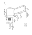
- FIG. 4 is a photograph of a handheld servo-controlled jet injector that may be used in the present invention.
- FIG. 5 is a cut-away schematic view of one embodiment of a controllable electromagnetic actuator suitable for use with the device of FIG. 4 ;
- FIG. 6 is a block diagram of one embodiment of the control system architecture usable with the device of FIG. 4 ;
- FIG. 7 illustrates delivery of minutien pins using a handheld servo-controlled jet injector as shown in FIG. 4 ;
- FIGS. 8A , 8 B, and 8 C illustrate delivery of a constant volume of 6 ⁇ m polystyrene beads in water to variable depths in post mortem rat skin using variable jet velocities (V jet ) with constant time at jet velocity (T jet ) and follow-through velocity (V ft );
- FIG. 9 is a schematic drawing of an embodiment of a cartridge design.
- FIG. 10 is a perspective diagram showing surface treatment using a servo-controlled multi-shot needle-free jet injection device.
- an exemplary needle-free transdermal transport device 100 e.g., a needle-free injector, with servo-control capability suitable for use with embodiments of the invention to transfer a substance across the surface 155 of a biological body 150 may be configured as follows. Although one type of device is described in detail, the method of the invention may be practiced with a wide range of needle-free transdermal transport devices, and is not limited to the exemplary device.
- the device 100 may be used to inject a liquid formulation of an active principle, for example, a drug, into a biological body such as an agriculture animal or human being.
- a biological body such as an agriculture animal or human being.
- the same device 100 may be used to collect a sample from a biological body 150 by withdrawing the collected sample through the surface 155 of the body and into an external reservoir 113 that may be provided within the device 100 .
- the device 100 typically includes a nozzle 114 to convey the substance through the surface 155 of the biological body at the required speed and diameter to penetrate the surface 155 (e.g., skin) as required.
- the substance ejected from the nozzle 114 forms a jet, the force of the jet determining the depth of penetration.
- the nozzle 114 generally contains a flat surface, such as the head 115 that can be placed against the skin, and forms an orifice 101 .
- the inner diameter of the orifice 101 controls the diameter of the transferred stream.
- the length of an aperture, or tube 103 , defining the orifice 101 also controls the transfer (e.g., injection) pressure.
- the nozzle 114 may be coupled to a syringe 112 defining a reservoir 113 for temporarily storing the transferred substance.
- the syringe 112 may include a plunger or piston 126 having at least a distal end slidably disposed within the reservoir 113 . Movement of the plunger 126 along the longitudinal axis of the syringe 112 in either direction creates a corresponding pressure within the reservoir 113 .
- a commercially-available needle-free syringe 112 can be attached to the device 100 , such as a model reference no. 100100 syringe 112 available from Equidyne Systems Inc. of San Diego, Calif.
- Electromagnetic actuator 125 is configured to generate a high-pressure pulse having a rapid rise time (e.g., less than 1 millisecond).
- the actuator is dynamically controllable, allowing for adjustments to the pressure-versus-time during actuation.
- the electromagnetic actuator 125 is configured to provide a linear force applied to the plunger 126 to achieve transdermal transfer of the substance. Transfer of the force can be accomplished with a force-transfer member 110 , such as a rigid rod slidably coupled through a bearing 111 .
- the actuator 125 may include a stationary component, such as a magnet assembly 105 , and a moveable component, such as coil assembly 104 .
- a force produced within the coil assembly 104 may be applied to the plunger 126 directly or indirectly through the rod 110 to achieve transdermal transfer of the substance.
- the actuator 125 , bearing 111 and syringe 112 are coupled to a frame or housing 102 that provides support and maintains fixed position of these elements during an actuation.
- the device 100 may include a user interface 120 that provides a status of the device.
- the user interface may provide an indication that the device is ready for an actuation.
- a light emitting diode (LED) coupled to a controller 108 may be enabled when sufficient conditions are satisfied for an injection.
- User interfaces 120 may include any suitable technology capable of conveying detailed information between a user and the device 100 .
- the user interface 120 may also enable an operator to provide inputs as user selections for one or more parameters. Thus, a user may identify parameters related to dose, sample, and/or the biological body, such as age, weight, etc.
- a power source 106 provides an electrical input to the coil assembly 104 of the actuator 125 .
- An electrical current applied to the coil assembly 104 in the presence of a magnetic field provided by the magnet assembly 105 results in a generation of a mechanical force capable of moving the coil assembly 104 and exerting work on the plunger 126 of the syringe 112 .
- the controller 108 is electrically coupled between the power source 106 and the actuator 125 .
- the controller 108 can selectively apply, suspend and otherwise adjust the electrical input signal provided by the power source 106 to the actuator 125 .
- the controller 50 may be a simple switch operable by a local interface. For example, a button provided on the housing 102 may be manipulated by a user, selectively applying and removing an electrical input from the power source 106 to the actuator 125 .
- the controller 108 may control elements, such as electrical circuits, that are adapted to selectively apply electrical power from the power source 106 to the actuator 125 , the electrical input being shaped by the selected application.
- the needle-free transdermal transport device 100 may include a remote interface 118 .
- the remote interface 118 may be used to transmit information, such as the status of the device 100 or of a substance contained therein to a remote source.
- the remote interface 118 may be in electrical communication with the controller 108 and may be used to forward inputs received from a remote source to the controller 108 to affect control of the actuator 125 .
- the remote interface 118 can include a network interface, such as a local area network interface, a wide-area network interface, a modem or a wireless interface capable of interfacing with a remote device/user over a public-switched telephone network.
- a network interface such as a local area network interface, a wide-area network interface, a modem or a wireless interface capable of interfacing with a remote device/user over a public-switched telephone network.
- the controller 108 may receive inputs from one or more sensors adapted to sense a respective physical property.
- the device 100 includes a transducer, such as a position sensor 116 B to indicate location of an object's coordinates (e.g., the coil's position) with respect to a selected reference.
- a displacement may be used to indicate movement from one position to another for a specific distance.
- the sensed parameter can be used as an indication of the plunger's position as an indication of dose.
- a proximity sensor may also be used to indicate a portion of the device, such as the coil, has reached a critical distance. This may be accomplished by sensing the position of the plunger 126 , the force-transfer member 110 , or the coil assembly 104 of the electromagnetic actuator 125 .
- an optical sensor such as an optical encoder can be used to count turns of the coil to determine the coil's position.
- Other types of sensors suitable for measuring position or displacement include inductive transducers, resistive sliding-contact transducers, photodiodes, and linear-variable-displacement-transformers (LVDT).
- a force transducer 116 A may be used to sense the force applied to the plunger 126 by the actuator 125 .
- a force transducer 116 A can be positioned between the distal end of the coil assembly and the force transfer member 110 , the transducer 116 A sensing force applied by the actuator 125 onto the force transfer member 110 .
- this member 110 is rigid, the force is directly transferred to the plunger 126 . The force tends to move the plunger 126 resulting in the generation of a corresponding pressure within the reservoir 113 .
- the actuator may be bi-directional, such that the mechanical force it generates may be applied in one of two directions. Accordingly, a positive force pushing the plunger 126 into the reservoir 113 creates a positive pressure tending to force a substance within the reservoir 113 out through the nozzle 114 . A negative force pulling the plunger 126 proximally away from the nozzle 114 creates a negative pressure or vacuum tending to suck a substance from outside the device through the nozzle 114 into the reservoir 113 .
- the substance may also be obtained from an ampoule, the negative pressure being used to pre-fill the reservoir 113 with the substance. Alternatively or in addition, the substance may come from the biological body representing a sampling of blood, tissue, and or other interstitial fluids.
- a solid body may be loaded into the reservoir by applying mechanical force in a first direction and thereafter driving the solid from the reservoir with applied force in a second direction opposite to the first direction.
- a pressure transducer (not shown) can also be provided to directly sense the pressure applied to a substance within the chamber.
- An electrical sensor 116 C may also be provided to sense an electrical input provided to the actuator 125 .
- the electrical sensor 116 C may sense one or more of coil voltage and coil current.
- Other sensors may include, for example, a gyrometer 116 D, an accelerometer 116 E, a strain gauge 116 F, a temperature sensor 116 G, an acoustic sensor or transducer 116 H, and/or a barometric sensor 116 J.
- the sensors 116 A, 116 B, 116 C, 116 D, 116 E, 116 F, 116 G, 116 H, and 116 J (generally 116 ) are coupled to the controller 108 providing the controller 108 with the sensed properties.
- the controller 108 may use one or more of the sensed properties to control application of an electrical input from the power source 106 to the actuator 125 , thereby controlling pressure generated within the syringe 112 to produce a desired transfer performance.
- a position sensor can be used to servo-control the actuator 125 to pre-position the coil assembly 104 at a desired location and to stabilize the coil 104 once positioned, and conclude an actuation cycle.
- movement of the coil assembly 104 from a first position to a second position corresponds to transfer of a corresponding volume of substance.
- the controller can include a processor programmed to calculate the volume based on coil position give the physical size of the reservoir.
- An actuation cycle generally corresponds to initiation of an electrical input to the actuator 125 to induce transfer of a substance and conclusion of the electrical input to halt transfer of the substance.
- a servo-control capability combined with the dynamically controllable electromagnetic actuator 125 enables adjustment of the pressure during the course of an actuation cycle.
- One or more of the sensors 116 can be used to further control the actuation cycle during the course of the transfer, or cycle.
- one or more of local and remote interfaces can also be used to further affect control of the actuation cycle.
- the controller 108 may be coupled with one or more other sensors (not shown) that detect respective physical properties of the biological surface. This information may be used to servo-control the actuator 125 to tailor the injection pressure, and, therefore, the depth of penetration of drug into the skin for a particular application. Moreover, the injection pressure may be varied over time.
- FIG. 2A A cross-sectional diagram of an electromagnetic impulse actuator 200 is shown in FIG. 2A .
- the actuator 200 includes a magnet assembly 205 defining an annular slotted cavity 214 and a coil assembly 203 slidably disposed therein.
- the stroke of the coil 203 may be controlled by the lengths of the coil and magnet assembly.
- the magnet assembly 205 includes a column of magnets 204 A, 204 B disposed along a central axis.
- the column of magnets may be created by stacking one or more magnetic devices, such as permanent magnets.
- a suitable category of strong, high-density magnets are rare-earth magnets, also known as Neodymium-Iron-Boron magnets (e.g., Nd 2 Fe 14 B), such as N50 magnets.
- the magnetic field produced by the magnets generally follows field lines 208 .
- the magnets 204 A, 204 B are attached at one end of a right-circular cylindrical shell 201 defining a hollowed axial cavity and closed at one end.
- An annular slot remains being formed between the magnets 204 A, 204 B and the interior walls of the case and accessible from the other end of the shell 201 .
- An exemplary shell 201 is formed with an outside diameter of about 40 mm and an inside diameter of about 31.6 mm, resulting in a wall thickness of about 4.2 mm.
- the magnets 204 A, 204 B may be cylindrical, having a diameter of about 25.4 mm.
- the shell 201 is preferably formed from a material adapted to promote containment of the magnetic fields produced by the magnets 204 A, 204 B.
- the shell 201 may be formed from a ferromagnetic material or a ferrite.
- One such ferromagnetic material includes an alloy referred to as carbon steel (e.g., American Iron and Steel Institute (AISI) 1026 carbon steel).
- An end cap 206 is also provided of similar ferromagnetic material being attached to the other end of the magnets 204 A, 204 B. Placement of the end cap 206 acts to contain the magnetic field therein and promoting a radially-directed magnetic field between the annular gap formed between the end cap 206 and the outer walls of the shell 201 .
- the end cap is generally thicker than the shell walls to promote containment of the magnetic fields as they loop into the end of the top magnet 204 A.
- the end cap 206 has an axial thickness of about 8 mm.
- the coil assembly 203 includes a coil 212 formed from a conducting material, such as copper wire wound about a bobbin 210 .
- the bobbin 210 can be cylindrical and defines an axial cavity sized to fit together with the coil 212 within the annular cavity 214 .
- the bobbin 210 may be substantially closed at the end juxtaposed to the annular cavity 214 .
- the closed end forms a force-bearing surface adapted to push against a plunger 214 or force-bearing rod 210 .
- a strong, yet light-weight coil assembly 203 is preferred for applications requiring a rapid generation of substantial force, such as needle-free transfers.
- the bobbin 210 is formed from a strong, yet light-weight readily machinable material, for example poly-acetal resins which are particularly well-suited to high temperature applications.
- the bobbin 210 is thin-walled to fit within the annular slot. A thin-walled bobbin 210 allows for a narrower annular slot 214 thereby promoting a greater magnetic field intensity across the gap.
- the bobbin 210 may have an outside diameter of about 27 mm, an internal diameter of about 26 mm, and an axial length of about 46 mm.
- the coil 212 consists of six layers of 28 gauge copper wire wound onto the bobbin 210 at a rate of about 115 windings per coil length (about 35 mm) resulting in about 700 turns total.
- the end cap 206 contains between about 0.63 and 0.55 Tesla (the value reducing outwardly along a radius measured from the center of the end cap 206 ).
- a current flowing through the coil 212 is positioned at right angles to the magnetic field 208 produced between the end cap 206 and the shell 201 wall. This results in the generation of a force on the coil directed along the longitudinal axis, the direction of the force depending upon the directional flow of the current.
- an electrical input, or drive voltage of about 100 volts is applied across the coil for a duration of about 1 millisecond representing the pierce phase of an actuation cycle.
- a lesser electrical input of about 2-5 volts is applied for the transfer phase.
- the coil 212 receives the electrical input signal through two electrical leads 216 .
- the shell 201 includes one or more apertures 218 through which the leads 216 are routed to the power source 106 ( FIG. 1 ).
- the closed end of the shell 201 may contain one or more additional apertures through which air may be transferred during movement of the coil. Without such apertures and given the relative tight tolerances of the gap between the coil 212 and the annular slot 214 , a pressure would build up to oppose movement of the coil.
- the bobbin 210 may also have one or more apertures 220 to further inhibit the build up of damping pressures during actuation.
- FIG. 2A shows the coil assembly 203 after or during an injection phase in which the coil is forced out of the shell 201 thereby advancing the front plate 215 .
- FIG. 2B shows the coil assembly 203 retracted within the shell 201 after a sampling phase in which the coil assembly 203 is drawn into the shell 201 .
- the conductive coil may be configured to carry a relatively high-amplitude electrical current to produce a substantial force resulting in the generation of a substantial pressure.
- the coil also provides a relatively low inductance, e.g., less than 100 millihenries to support high-frequency operation.
- One way to provide high-current capacity with the low inductance is using a coil formed by a large-diameter conductor that is configured with a low number of turns (e.g., 1 to 3 turns).
- the result is a pressure actuator capable of generating a high-pressure pulse with a rapid rise time. Additionally, operation of the actuator is both controllable and highly predictable given the physical properties of the actuator and the input electrical current. Still further, the actuator is reversible providing forces in opposing directions based on the direction of current flow within the coil.
- FIG. 3A an exemplary time varying electrical input is shown.
- the curve represents variation in an electrical current applied to the coil assembly 104 of the actuator 125 .
- an electrical current is applied to the coil 104 .
- the current rises from a rest value (e.g., zero amps) to a maximum value I P remaining at this maximum for a selectable duration and then transitioning to a different current value I T at a later time t 1 .
- the current amplitude may remain substantially at this value, or continue to vary with time until a later time t 2 , at which the current returns to a rest value.
- the entire period of time defined between times t 2 and t 0 can be referred to as an actuation period, or actuation cycle.
- the period defined between times t 1 and t 0 can be referred to as a piercing phase.
- the high current value I p induces a corresponding high pressure that can be used to pierce the surface of a biological body without using a needle or lance.
- the remainder of the actuation cycle defined between times t 2 and t 1 can be referred to as a transfer phase.
- the relatively lower current value I T induces a lesser pressure that can be used to transfer a substance from the reservoir 113 ( FIG. 1 ) to the biological body through the perforation in the surface created during the piercing phase.
- FIG. 3B An exemplary plot of a pressure induced within the reservoir 113 ( FIG. 1 ) in response to the electrical input is illustrated in FIG. 3B .
- the pressure rises from an initial rest value to a relative maximum value, P p , at a time t 0 , perhaps with a slight delay ⁇ resulting from the transfer characteristics of the electrical coil.
- This pressure value can be used to create a jet as described above in relation to FIG. 1 .
- the pressure similarly reduces to a lesser value P T determined to achieve a desired transfer of the substance.
- the transfer phase continues until a desired volume of the substance is transferred, then the pressure is removed concluding the actuation cycle.
- a servo-controlled injector includes a specially-designed electromagnetic pressure actuator configured in combination with a servo controller to generate an injection pressure responsive in real-time to one or more physical properties (e.g., pressure, position, volume, etc.).
- the servo-controlled injector is a needle-free device.
- the electromagnetic pressure actuator generates a high-pressure pulse having a rapid rise time (e.g., less than 1 millisecond) for injecting a formulation beneath the skin. With such a rapid rise time, an entire transfer can be completed in less than about 10 milliseconds.
- the pressure provided by the actuator can be varied during the actuation of a single injection to achieve a desired result.
- a first high-pressure is initially provided to the formulation to penetrate the outer surface layer of an animal's skin. Once the skin is penetrated, the pressure is reduced to a second, lower pressure for the remainder of the injection.
- the servo-controller can be used to determine when the skin is penetrated by sensing a change in pressure within the chamber and to adjust the injection pressure accordingly.
- a servo-controller 108 receives input signals from the one or more sensors 116 and generates an output signal according to a predetermined relationship.
- the servo-controller output can be used to control the pressure by controlling the amplitude of electrical current driving the controllable actuator.
- Real-time control can be accomplished by the servo controller 108 repeatedly receiving inputs from the sensors 116 , processing the inputs according to the predetermined relationship and generating corresponding outputs.
- the entire sense-control process is preferably performed numerous times during the period of the injection.
- a servo-controller 108 can include a high-speed microprocessor capable of processing signals received from the sensors and rapidly providing corresponding output signals at a rate of 100 kHz (i.e., every 10 microseconds). Such rapid response times provide hundreds of opportunities to adjust pressure during the course of a single 5 to 10 millisecond injection.
- a servo-controlled jet injector suitable for use with embodiments of the invention includes a hand-held injector 400 , a real-time controller (not shown), and a linear power amplifier
- the hand held injector 400 comprises a voice coil 420 that slides freely along a steel extrusion as it moves in the motor 410 , an ampoule, such as commercially available disposable InjexTM 30 ampoule 430 (0.3 mL; part #100100 available from Injex-Equidyne Systems, Inc., based in Fullerton, Calif.), a push button activation switch 440 , housing 450 that surrounds the interior components of the injector, and wires 460 that connect to a controller.
- an ampoule such as commercially available disposable InjexTM 30 ampoule 430 (0.3 mL; part #100100 available from Injex-Equidyne Systems, Inc., based in Fullerton, Calif.
- a push button activation switch 440 housing 450 that surrounds the interior components of the
- the InjexTM 30 ampoule 430 is screwed into a front plate 535 of the jet injector and the piston 510 is threaded into the front of the moving coil 420 .
- the choice of ampoule may be based on availability, relatively low cost, proven performance, and ease with which it may be adapted for inclusion into the injection device.
- the internal diameter of the ampoule may taper at the tip to form a nozzle orifice 520 having a diameter of, e.g., 220 ⁇ 5 ⁇ m. In the illustrated embodiment, a delivery volume of 300 ⁇ L is realized with a 30 mm stroke.
- the custom-designed linear Lorentz-force motor consists of 582 turns of 360 ⁇ m diameter enameled copper wire wound six layers deep on a custom-designed, thin-walled former.
- the former may be machined from polyetherimide stock; the material choice that permits minimization of the moving mass ( ⁇ 50 g) and avoids the drag incurred by induction of eddy currents in a conducting former.
- Current applied to the copper wire creates an axial Lorentz force of up to 200 N with a force constant of 10.8 ⁇ 0.5 N/A.
- the total DC resistance of the coil may be approximately 11.3 ⁇ .
- the voice coil 420 slides freely and smoothly on the bearing surfaces 550 and inside a 1026 carbon-steel extrusion casing 560 that also forms the magnetic circuit.
- the latter includes two 0.4 MN/m 2 (50 MGOe) NdFeB magnets 525 inserted into the casing.
- the magnetic flux density in the field gap may be approximately 0.6 Tesla.
- Plastic-laminated, flexible copper ribbons may form the electrical connections to the coil.
- a 10 k ⁇ linear potentiometer (i.e., displacement transducer) 540 with >1 kHz bandwidth may be mounted to the linear guide system monitors the position of the coil.
- the position sensor is coupled to the coil via a movable pin that is mounted on the leading edge of the former.
- the system is powered by a 4 kW Techron amplifier, controlled by a PC-based data acquisition and control system running in National Instruments LabviewTM 8.5, which allows the testing of a variety of waveforms and concomitant evaluation of both the current and displacement.
- High-speed position monitoring and servo-control of coil position may be achieved using a compact reconfigurable system comprising a real-time controller (cRIO-9004, National Instruments, Austin, Tex.) embedded in a reconfigurable field-programmable gate-array (FPGA) chassis (cRIO-9104).
- the controller may execute a LabVIEW 8.5 Real-Time “host” application that interacts with the FPGA circuitry, perform high-level injection trajectory planning, interpret user commands, and provide real-time and post-injection feedback.
- the user interface of the host application may be broadcast by a web-server running on the controller, and operated from a web-browser on a networked laptop computer.
- the position-based jet-injector control algorithm has two components: (i) a velocity-driven feed-forward (FF) model that predicts the voltage required to achieve a given jet-speed, and (ii) a linear proportional-integral (PI) displacement feed-back controller to counteract noise and disturbances to the injector system, as depicted in FIG. 6 . Both components are active when the coil is in motion; FF dominates during injections while the feedback dominates during refilling and holding and ensures that the correct volume of fluid is delivered.
- FF velocity-driven feed-forward
- PI linear proportional-integral
- Injection waveforms are generated with two distinct phases of delivery: a brief high-speed phase followed by a second lower speed phase of variable duration.
- the first phase accelerates the coil to the desired jet velocity (V jet ) required for penetration where it is maintained for a pre-determined period of time (T jet ) after which the coil is gently decelerated to a lower follow-through velocity (V ft ). This velocity is maintained until the coil position approaches the displacement at which the desired injection volume (V) is realized.
- Feedback of jet speed is implicit from position feedback, with the derivative or slope of the coil vs. time plot representing velocity. The integral of the position vs. time plot yields the volume being delivered.
- the jet injection device of FIG. 1 may be used to inject a solid body, such as bare or functionalized polymer wires or metal wires across a surface of a biological body, e.g., into tissue (e.g., brain) or some other material for use as recording electrodes.
- a solid body such as bare or functionalized polymer wires or metal wires across a surface of a biological body, e.g., into tissue (e.g., brain) or some other material for use as recording electrodes.
- tissue e.g., brain
- the dimensions and depth of injection may vary depending on use.
- wires (polymer or metal) for neural recording may be tethered at one end to the piston tip of a fluid-filled ampoule and injected into tissue such that the tip of each wire protrudes from the tissue surface, allowing the wires to be integrated into a microelectrode array assembly for recording.
- wires may range in diameter from 10 ⁇ m to 200 ⁇ m and may have lengths of 200 ⁇ m to 15 mm.
- a photograph shows delivery of 0.1 mm ⁇ 11 mm metal pins or wires (i.e., minutien pins) to post mortem rat skin using a servo-controlled linear Lorentz-force actuator as shown in FIG. 4 .
- Individual minutien pins were seated in the nozzle of fluid filled ampoules, which were then apposed to tissue and the pins ejected. Pins were shown to completely penetrate rat skin when delivered by ejection of 50 ⁇ L of fluid at a jet speed of 150 m/s. T jet and V ft were constant at 5 ms and 50 m/s respectively.
- the device of FIG. 1 may be used to inject particles ⁇ 100 ⁇ m in diameter (e.g., nanoparticles and microparticles) suspended in fluid into tissue, tissue analogues, etc.
- the particles may be functionalized.
- the suspended particles may be loaded into the device by utilizing the bidirectional nature of the motor.
- Microparticles having diameters >100 ⁇ m may be ejected with some modification of the nozzle orifice; for example the nozzle diameter may be enlarged to accommodate delivery of larger particles, nozzle length may be reduced to reduce fluid pressure drop, or the taper of the nozzle may be changed.
- FIG. 8A representative photographs showing delivery of 6 ⁇ m spherical polystyrene beads in water to post mortem rat skin using the injection device of FIG. 4 .
- Beads were delivered using V jets of 100, 125, 140, and 150 m/s with a constant T jet of 5 ms and V ft of 50 m/s; a V jet of 100 m/s failed to penetrate the tissue.
- Post injection the tissue was cut down the midline of the injection site, splayed injection side up, and photographed.
- the volume of beads in water injected into the tissue may be calculated as the difference in tissue weight, pre- to post-injection after subtracting the weight of any fluid remaining on the surface of the tissue post injection; the latter being blotted to pre-weighed filter paper and re-weighed.
- FIG. 8B is a graph depicting the total volume of beads in water delivered and the volume of beads in water delivered to the tissue as a function of jet velocity. Total volume delivered was >80% while volume delivered specifically to the tissue varied with jet velocity. Extremes at 100 m/s and 150 m/s represent insufficient pressure to penetrate the tissue or complete penetration of the tissue respectively.
- FIG. 8C is a graph showing that penetration depth increases with increasing jet velocity, as depicted in FIG. 8A .
- the variation in depth observed at 150 m/s is independent of the velocity. Rather it reflects the variation in the total depth of the tissue as this velocity repeatably completely penetrated the tissue sample.
- the ampoule and/or nozzle of the device illustrated in FIG. 1 may be modified to hold a pre-loaded, single use cartridge 900 .
- the cartridge may be made out of a clear plastic, for example polycarbonate with a nozzle geometry capable of holding a capsule or implant 940 taking the shape of, for example a sphere, rod, etc. Contiguous with the capsule receptacle is a through hole passage that lines up with a similar passage in the stainless steel shaft 910 holding the piston. The distal end of the nozzle may be threaded, allowing it to be seated onto the end of a stainless steel shaft containing a plunger that may be loaded with fluid.
- an O-ring 920 may be disposed proximate the threads.
- Both the stainless steel shaft and the plunger may be made from materials that can be sterilized.
- a sterile cover 930 may be placed over an end of the ampoule. Actuation results in the plunger forcing the fluid through the capsule orifice, causing the implant 940 to be ejected from the cartridge through the sterile cover and into the target tissue.
- the actuator may be used to propel shards of glass-forming sugars such as trehalose and sucrose that contain drug into tissue.
- Sugars are often used as excipients because their transition temperature correlates with the storage temperature of the product.
- Another embodiment relates to use of the servo-controlled jet injector platform to deliver a series of incremental volumes of fluid containing one or more solid particulates to a target body, such as an agriculture animal, pet, or human being. Ejection of the fluid drives the particulates into the target body to pre-determined depths and may result in the formation of, for example self-assembling scaffolds or multi-layered structures. Assembly may be due to:
- injection may be accomplished by positioning a needle-free injector 1000 including a number of independent jet actuators 1002 and having an ampoule attached thereto, e.g., needle-free transdermal transport device 100 or hand-held injector 400 , proximate a surface 155 of the target body, e.g., tissue of a biological body, injecting a substance into the target body, and, while injecting, moving the needle-free injector along the surface, thereby sweeping the surface.
- the surface may be swept using one or more actuators.
- the sweeping motion of the device may be servo-controlled using an accelerometer 1004 , e.g., disposed in an accelerometer/camera package, while the orientation of the device during the sweeping motion may be controlled using a 3-axis gyrometer.
- the needle-free injector may inject, e.g., individually controlled jet streams 1006 along a number of injection sites that may be marked by markers 1008 disposed in the swept area, i.e., in the treated surface region 1008 .
- the needle-free injector may be in contact with the target body.
- the needle-free injector may be moved along the surface in a plane.
- the substance may be injected to a plurality of depths below the surface.
- the injected substance may define a multi-layered structure including layers disposed at different depths beneath the surface.
- the substance may include or consist essentially of a solid body.
Landscapes
- Health & Medical Sciences (AREA)
- Engineering & Computer Science (AREA)
- Hematology (AREA)
- Anesthesiology (AREA)
- Biomedical Technology (AREA)
- Heart & Thoracic Surgery (AREA)
- Vascular Medicine (AREA)
- Life Sciences & Earth Sciences (AREA)
- Animal Behavior & Ethology (AREA)
- General Health & Medical Sciences (AREA)
- Public Health (AREA)
- Veterinary Medicine (AREA)
- Bioinformatics & Cheminformatics (AREA)
- Pharmacology & Pharmacy (AREA)
- Infusion, Injection, And Reservoir Apparatuses (AREA)
Priority Applications (1)
| Application Number | Priority Date | Filing Date | Title |
|---|---|---|---|
| US13/269,322 US8821434B2 (en) | 2010-10-07 | 2011-10-07 | Delivery of a solid body and/or a fluid using a linear Lorentz-force actuated needle-free jet injection system |
Applications Claiming Priority (3)
| Application Number | Priority Date | Filing Date | Title |
|---|---|---|---|
| US39105310P | 2010-10-07 | 2010-10-07 | |
| US40535510P | 2010-10-21 | 2010-10-21 | |
| US13/269,322 US8821434B2 (en) | 2010-10-07 | 2011-10-07 | Delivery of a solid body and/or a fluid using a linear Lorentz-force actuated needle-free jet injection system |
Publications (2)
| Publication Number | Publication Date |
|---|---|
| US20120095435A1 US20120095435A1 (en) | 2012-04-19 |
| US8821434B2 true US8821434B2 (en) | 2014-09-02 |
Family
ID=45044687
Family Applications (1)
| Application Number | Title | Priority Date | Filing Date |
|---|---|---|---|
| US13/269,322 Active 2032-02-24 US8821434B2 (en) | 2010-10-07 | 2011-10-07 | Delivery of a solid body and/or a fluid using a linear Lorentz-force actuated needle-free jet injection system |
Country Status (5)
| Country | Link |
|---|---|
| US (1) | US8821434B2 (enExample) |
| EP (2) | EP3403682A1 (enExample) |
| JP (1) | JP5934710B2 (enExample) |
| CN (1) | CN103298507B (enExample) |
| WO (1) | WO2012048268A2 (enExample) |
Cited By (7)
| Publication number | Priority date | Publication date | Assignee | Title |
|---|---|---|---|---|
| US20110166549A1 (en) * | 2008-07-09 | 2011-07-07 | Massachusetts Institute Of Technology | Bi-directional motion of a lorentz-force actuated needle-free injector (nfi) |
| US8992466B2 (en) | 2005-02-11 | 2015-03-31 | Massachusetts Institute Of Technology | Controlled needle-free transport |
| US9333060B2 (en) | 2009-12-15 | 2016-05-10 | Massachusetts Institute Of Technology | Plaque removal and differentiation of tooth and gum |
| US9517030B2 (en) | 2009-09-01 | 2016-12-13 | Massachusetts Institute Of Technology | Nonlinear system identification techniques and devices for discovering dynamic and static tissue properties |
| US20170164933A1 (en) * | 2015-12-15 | 2017-06-15 | Portal Instruments, Inc. | Biospecimen extraction apparatus |
| US20200123485A1 (en) * | 2018-10-19 | 2020-04-23 | Nutech Ventures | Bioprinter devices, systems and methods for printing soft gels for the treatment of musculoskeletal and skin disorders |
| WO2022192632A1 (en) * | 2021-03-12 | 2022-09-15 | Vaccination Kiosks, Llc | Automatic needle-free injector container unit system |
Families Citing this family (20)
| Publication number | Priority date | Publication date | Assignee | Title |
|---|---|---|---|---|
| CN103298507B (zh) | 2010-10-07 | 2015-08-26 | 麻省理工学院 | 采用线性洛仑兹力致动的无针射流注射系统递送固体和/或流体 |
| WO2012048277A2 (en) | 2010-10-07 | 2012-04-12 | Massachusetts Institute Of Technology | Injection methods using a servo-controlled needle-free injector |
| ITMI20132067A1 (it) | 2013-12-11 | 2015-06-12 | Dante Lorini | Apparecchiatura per l'inoculazione transdermica di medicamenti |
| US9782549B2 (en) * | 2014-10-22 | 2017-10-10 | Ethicon, Inc. | Distance indicators for medicinal spray devices |
| EP3037119A1 (en) * | 2014-12-23 | 2016-06-29 | Hipra Scientific, S.L.U. | Device for administering medicinal products |
| EP3040036B1 (de) * | 2014-12-29 | 2017-10-11 | Erbe Elektromedizin GmbH | Instrumentenkopf, Applikationsinstrument mit entsprechendem Instrumentenkopf und Applikationssystem |
| PL3040101T3 (pl) * | 2014-12-29 | 2017-08-31 | Erbe Elektromedizin Gmbh | Urządzenie zasilające do wytwarzania impulsowego strumienia płynu, system aplikacyjny z urządzeniem zasilającym i pamięć czytelna dla komputera |
| GB201501697D0 (en) * | 2015-02-02 | 2015-03-18 | Glide Pharmaceutical Technologies Ltd | Injection device |
| JP6583747B2 (ja) | 2015-09-29 | 2019-10-02 | 大日本印刷株式会社 | インプリント用のモールドおよびその製造方法 |
| US10737032B2 (en) * | 2015-11-25 | 2020-08-11 | Portal Instruments, Inc. | Needle-free transdermal injection device |
| CN105943365B (zh) * | 2016-05-31 | 2018-04-17 | 张岩 | 电子针灸无痛针疗仪及染料 |
| JP2020501846A (ja) * | 2016-12-21 | 2020-01-23 | ダイナミック マグネティクス,エルエルシー | 自動注入器に動力供給するために使用される磁気ドライバデバイス |
| JP7328970B2 (ja) | 2017-09-12 | 2023-08-17 | ポータル インストルメンツ, インク. | 回転モータ式経皮注射装置 |
| KR102209394B1 (ko) | 2018-04-20 | 2021-01-29 | 경상대학교산학협력단 | 마이크로젯 약물 전달 시스템 |
| CN116407710A (zh) * | 2018-07-25 | 2023-07-11 | 株式会社大赛璐 | 注入器、以及使用该注入器向注入对象的细胞内注入包含生物分子的溶液的注入方法 |
| FR3092495B1 (fr) * | 2019-02-07 | 2021-11-26 | Oreal | Dispositif d’injection sans aiguille |
| JP7530177B2 (ja) * | 2020-01-31 | 2024-08-07 | 朝日インテック株式会社 | 薬液注入装置 |
| KR102513098B1 (ko) * | 2020-11-06 | 2023-03-23 | 주식회사 제이시스메디칼 | 무침 주사기 |
| CN113384778A (zh) * | 2021-06-10 | 2021-09-14 | 苏芮 | 一种可控的无针注射装置 |
| CN116637255B (zh) * | 2023-04-23 | 2024-06-07 | 卓优医疗(苏州)有限公司 | 一种用于无针注射装置的微剂量调节方法 |
Citations (24)
| Publication number | Priority date | Publication date | Assignee | Title |
|---|---|---|---|---|
| US5865795A (en) * | 1996-02-29 | 1999-02-02 | Medi-Ject Corporation | Safety mechanism for injection devices |
| US5879327A (en) * | 1994-04-06 | 1999-03-09 | Moreau Defarges Alain | Needleless jet injection device |
| US6258062B1 (en) * | 1999-02-25 | 2001-07-10 | Joseph M. Thielen | Enclosed container power supply for a needleless injector |
| US20030083618A1 (en) | 2001-10-26 | 2003-05-01 | Massachusetts Institute Of Technology | Transdermal transport device with an electrolytic actuator |
| WO2003035149A1 (en) | 2001-10-24 | 2003-05-01 | Weston Medical Limited | Needleless injector with shock absorbing means between ram and piston |
| WO2003039635A2 (en) | 2001-10-26 | 2003-05-15 | Massachusetts Institute Of Technology | Needleless injector |
| WO2004022138A2 (en) | 2002-09-06 | 2004-03-18 | Massachusetts Institute Of Technology | Needless drug injection device |
| US20040260234A1 (en) * | 2003-04-21 | 2004-12-23 | Ravi Srinivasan | Apparatus and methods for repetitive microjet durg delivery priority statement |
| WO2006086774A2 (en) | 2005-02-11 | 2006-08-17 | Massachusetts Institute Of Technology | Needle-free transdermal transport device |
| WO2006086720A2 (en) | 2005-02-11 | 2006-08-17 | Massachusetts Institute Of Technology | Controlled needle-free transport device |
| US20070055200A1 (en) * | 2005-08-10 | 2007-03-08 | Gilbert Scott J | Needle-free jet injection drug delivery device |
| WO2007058966A1 (en) | 2005-11-11 | 2007-05-24 | Massachusetts Institute Of Technology | Controlled needle-free eye injector |
| US20080033351A1 (en) * | 2006-08-04 | 2008-02-07 | Allergan, Inc. | Ocular implant delivery assemblies with distal caps |
| WO2008027579A1 (en) | 2006-09-01 | 2008-03-06 | Massachusetts Institute Of Technology | Needle-free injector device with autoloading capability |
| US20080274979A1 (en) * | 2007-03-14 | 2008-11-06 | Rutledge Ellis-Behnke | Treatment of leaky or damaged tight junctions and enhancing extracellular matrix |
| US20090240230A1 (en) | 2006-06-28 | 2009-09-24 | Perf-Action Technologies Ltd. | Intradermal Needles Injection Device |
| US7833189B2 (en) | 2005-02-11 | 2010-11-16 | Massachusetts Institute Of Technology | Controlled needle-free transport |
| US20110054355A1 (en) | 2009-09-01 | 2011-03-03 | Hunter Ian W | Identification Techniques and Device for Testing the Efficacy of Beauty Care Products and Cosmetics |
| US20110054354A1 (en) | 2009-09-01 | 2011-03-03 | Massachusetts Institute Of Technology | Nonlinear System Identification Techniques and Devices for Discovering Dynamic and Static Tissue Properties |
| US20110071505A1 (en) * | 2009-09-21 | 2011-03-24 | Matthew Rickard | Intraocular Pressure Sensor with External Pressure Compensation |
| US20110082388A1 (en) | 2008-07-09 | 2011-04-07 | Massachusetts Institute Of Technology | Bi-directional motion of a lorentz-force actuated needle-free injector (nfi) |
| US20110143310A1 (en) | 2009-12-15 | 2011-06-16 | Hunter Ian W | Lorentz-Force Actuated Cleaning Device |
| WO2012048268A2 (en) | 2010-10-07 | 2012-04-12 | Massachusetts Instiute Of Technology | Delivery of a solid body and/or a fluid using a linear lorentz-force actuated needle-free jet injection system |
| WO2012048277A2 (en) | 2010-10-07 | 2012-04-12 | Massachusetts Institute Of Technology | Injection methods using a servo-controlled needle-free injector |
Family Cites Families (11)
| Publication number | Priority date | Publication date | Assignee | Title |
|---|---|---|---|---|
| TW360548B (en) * | 1993-04-08 | 1999-06-11 | Powderject Res Ltd | Products for therapeutic use |
| WO2000043058A1 (en) * | 1999-01-22 | 2000-07-27 | Powderject Research Limited | Method of enhancing needleless transdermal powdered drug delivery |
| US6224567B1 (en) * | 1999-09-08 | 2001-05-01 | Cambridge Biostability Limited | Modified disposable injector device |
| GB0100756D0 (en) * | 2001-01-11 | 2001-02-21 | Powderject Res Ltd | Needleless syringe |
| EP1684238A1 (de) * | 2005-01-21 | 2006-07-26 | Swisscom Mobile AG | Identifikationsverfahren und System und dafür geeignete Vorrichtung |
| JP2008535541A (ja) * | 2005-03-04 | 2008-09-04 | ストラタジェント ライフ サイエンシーズ, インコーポレイテッド | マイクロジェットデバイスおよび薬剤供給方法 |
| US7704704B2 (en) * | 2005-09-28 | 2010-04-27 | The Texas A&M University System | Implantable system for glucose monitoring using fluorescence quenching |
| WO2007061896A1 (en) * | 2005-11-17 | 2007-05-31 | Zogenix, Inc. | Delivery of viscous formulations by needle-free injection |
| JP2008206477A (ja) * | 2007-02-27 | 2008-09-11 | National Cardiovascular Center | 無針注射器を用いた細胞播種法 |
| US8915866B2 (en) * | 2008-01-18 | 2014-12-23 | Warsaw Orthopedic, Inc. | Implantable sensor and associated methods |
| WO2009153729A1 (en) * | 2008-06-19 | 2009-12-23 | Koninklijke Philips Electronics N.V. | Parenteral medicament delivery device |
-
2011
- 2011-10-07 CN CN201180058911.4A patent/CN103298507B/zh not_active Expired - Fee Related
- 2011-10-07 EP EP18177310.2A patent/EP3403682A1/en not_active Withdrawn
- 2011-10-07 WO PCT/US2011/055443 patent/WO2012048268A2/en not_active Ceased
- 2011-10-07 JP JP2013532987A patent/JP5934710B2/ja not_active Expired - Fee Related
- 2011-10-07 US US13/269,322 patent/US8821434B2/en active Active
- 2011-10-07 EP EP11788243.1A patent/EP2621565B1/en not_active Not-in-force
Patent Citations (59)
| Publication number | Priority date | Publication date | Assignee | Title |
|---|---|---|---|---|
| US5879327A (en) * | 1994-04-06 | 1999-03-09 | Moreau Defarges Alain | Needleless jet injection device |
| US5865795A (en) * | 1996-02-29 | 1999-02-02 | Medi-Ject Corporation | Safety mechanism for injection devices |
| US6258062B1 (en) * | 1999-02-25 | 2001-07-10 | Joseph M. Thielen | Enclosed container power supply for a needleless injector |
| WO2003035149A1 (en) | 2001-10-24 | 2003-05-01 | Weston Medical Limited | Needleless injector with shock absorbing means between ram and piston |
| WO2003037404A1 (en) | 2001-10-26 | 2003-05-08 | Massachusetts Institute Of Technology | Microneedle transdermal transport device |
| US7651475B2 (en) | 2001-10-26 | 2010-01-26 | Massachusetts Institute Of Technology | Microneedle transport device |
| WO2003037403A1 (en) | 2001-10-26 | 2003-05-08 | Massachusetts Institute Of Technology | Microneedle transport device |
| WO2003037406A2 (en) | 2001-10-26 | 2003-05-08 | Massachusetts Institute Of Technology | Transdermal transport device with an electrolytic actuator |
| US7364568B2 (en) | 2001-10-26 | 2008-04-29 | Massachusetts Institute Of Technology | Microneedle transdermal transport device |
| WO2003037407A1 (en) | 2001-10-26 | 2003-05-08 | Massachusetts Institute Of Technology | Transdermal transport device with suction |
| WO2003039635A2 (en) | 2001-10-26 | 2003-05-15 | Massachusetts Institute Of Technology | Needleless injector |
| WO2003037405A1 (en) | 2001-10-26 | 2003-05-08 | Massachusetts Institute Of Technology | Impedance sensor |
| US7645263B2 (en) | 2001-10-26 | 2010-01-12 | Massachusetts Institute Of Technology | Impedance sensor |
| US20030083618A1 (en) | 2001-10-26 | 2003-05-01 | Massachusetts Institute Of Technology | Transdermal transport device with an electrolytic actuator |
| US20080281273A1 (en) | 2001-10-26 | 2008-11-13 | Massachusetts Institute Of Technology | Microneedle transdermal transport device |
| US6939323B2 (en) | 2001-10-26 | 2005-09-06 | Massachusetts Institute Of Technology | Needleless injector |
| US7066922B2 (en) | 2001-10-26 | 2006-06-27 | Massachusetts Institute Of Technology | Transdermal transport device with suction |
| US7429258B2 (en) | 2001-10-26 | 2008-09-30 | Massachusetts Institute Of Technology | Microneedle transport device |
| US7425204B2 (en) | 2001-10-26 | 2008-09-16 | Massachusetts Institute Of Technology | Needleless injector |
| US20040106894A1 (en) * | 2002-09-06 | 2004-06-03 | Massachusetts Institute Of Technology | Needleless drug injection device |
| US8105270B2 (en) | 2002-09-06 | 2012-01-31 | Massachusetts Institute Of Technology | Measuring properties of an anatomical body |
| WO2004022138A2 (en) | 2002-09-06 | 2004-03-18 | Massachusetts Institute Of Technology | Needless drug injection device |
| WO2004021882A2 (en) | 2002-09-06 | 2004-03-18 | Massachusetts Institute Of Technology | Measuring properties of an anatomical body |
| US20100004624A1 (en) | 2002-09-06 | 2010-01-07 | Massachusetts Institute Of Technology | Measuring properties of an anatomical body |
| US7530975B2 (en) | 2002-09-06 | 2009-05-12 | Massachusetts Institute Of Technology | Measuring properties of an anatomical body |
| US20040260234A1 (en) * | 2003-04-21 | 2004-12-23 | Ravi Srinivasan | Apparatus and methods for repetitive microjet durg delivery priority statement |
| US7833189B2 (en) | 2005-02-11 | 2010-11-16 | Massachusetts Institute Of Technology | Controlled needle-free transport |
| US20060258986A1 (en) | 2005-02-11 | 2006-11-16 | Hunter Ian W | Controlled needle-free transport |
| WO2006086720A2 (en) | 2005-02-11 | 2006-08-17 | Massachusetts Institute Of Technology | Controlled needle-free transport device |
| WO2006086774A2 (en) | 2005-02-11 | 2006-08-17 | Massachusetts Institute Of Technology | Needle-free transdermal transport device |
| US8328755B2 (en) | 2005-02-11 | 2012-12-11 | Massachusetts Institute Of Technology | Controlled needle-free transport |
| US20110257626A1 (en) | 2005-02-11 | 2011-10-20 | Massachusetts Institute Of Technology | Controlled needle-free transport |
| US20080009788A1 (en) | 2005-02-11 | 2008-01-10 | Hunter Ian W | Surface injection device |
| WO2006086719A1 (en) | 2005-02-11 | 2006-08-17 | Massachusetts Institute Of Technology | Surface injection device |
| US20070055200A1 (en) * | 2005-08-10 | 2007-03-08 | Gilbert Scott J | Needle-free jet injection drug delivery device |
| US20070129693A1 (en) | 2005-11-11 | 2007-06-07 | Hunter Ian W | Controlled needle-free eye injector |
| WO2007058966A1 (en) | 2005-11-11 | 2007-05-24 | Massachusetts Institute Of Technology | Controlled needle-free eye injector |
| US20090240230A1 (en) | 2006-06-28 | 2009-09-24 | Perf-Action Technologies Ltd. | Intradermal Needles Injection Device |
| US20080033351A1 (en) * | 2006-08-04 | 2008-02-07 | Allergan, Inc. | Ocular implant delivery assemblies with distal caps |
| US20100016827A1 (en) | 2006-09-01 | 2010-01-21 | Massachusetts Institute Of Technology | Needle-free injector device with autoloading capability |
| WO2008027579A1 (en) | 2006-09-01 | 2008-03-06 | Massachusetts Institute Of Technology | Needle-free injector device with autoloading capability |
| US8172790B2 (en) | 2006-09-01 | 2012-05-08 | Massachusetts Institute Of Technology | Needle-free injector device with autoloading capability |
| US20080274979A1 (en) * | 2007-03-14 | 2008-11-06 | Rutledge Ellis-Behnke | Treatment of leaky or damaged tight junctions and enhancing extracellular matrix |
| US20110082388A1 (en) | 2008-07-09 | 2011-04-07 | Massachusetts Institute Of Technology | Bi-directional motion of a lorentz-force actuated needle-free injector (nfi) |
| US20110166549A1 (en) | 2008-07-09 | 2011-07-07 | Massachusetts Institute Of Technology | Bi-directional motion of a lorentz-force actuated needle-free injector (nfi) |
| US20110054355A1 (en) | 2009-09-01 | 2011-03-03 | Hunter Ian W | Identification Techniques and Device for Testing the Efficacy of Beauty Care Products and Cosmetics |
| US20110054354A1 (en) | 2009-09-01 | 2011-03-03 | Massachusetts Institute Of Technology | Nonlinear System Identification Techniques and Devices for Discovering Dynamic and Static Tissue Properties |
| WO2011028719A2 (en) | 2009-09-01 | 2011-03-10 | Massachusetts Institute Of Technology | Nonlinear system identification techniques and devices for discovering dynamic and static tissue properties |
| WO2011028716A1 (en) | 2009-09-01 | 2011-03-10 | Massachusetts Institute Of Technology | Nonlinear system identification technique for testing the efficacy of skin care products |
| US20110071505A1 (en) * | 2009-09-21 | 2011-03-24 | Matthew Rickard | Intraocular Pressure Sensor with External Pressure Compensation |
| WO2011084511A1 (en) | 2009-12-15 | 2011-07-14 | Massachusetts Institute Of Technology | Jet injector use in oral evaluation |
| US20110311939A1 (en) | 2009-12-15 | 2011-12-22 | Massachusetts Institute Of Technology | Plaque Removal and Differentiation of Tooth and Gum |
| US20120003601A1 (en) | 2009-12-15 | 2012-01-05 | Massachusetts Institute Of Technology | Jet Injector Use In Oral Evaluation |
| WO2011075545A1 (en) | 2009-12-15 | 2011-06-23 | Massachusetts Institute Of Technogy | Lorentz-force actuated cleaning device |
| WO2011075535A1 (en) | 2009-12-15 | 2011-06-23 | Massachusetts Institute Of Technology | Plaque removal and differentiation of tooth and gum |
| US20110143310A1 (en) | 2009-12-15 | 2011-06-16 | Hunter Ian W | Lorentz-Force Actuated Cleaning Device |
| WO2012048268A2 (en) | 2010-10-07 | 2012-04-12 | Massachusetts Instiute Of Technology | Delivery of a solid body and/or a fluid using a linear lorentz-force actuated needle-free jet injection system |
| WO2012048277A2 (en) | 2010-10-07 | 2012-04-12 | Massachusetts Institute Of Technology | Injection methods using a servo-controlled needle-free injector |
| US20120089114A1 (en) | 2010-10-07 | 2012-04-12 | Massachusetts Institute Of Technology | Injection methods using a servo-controlled needle-free injector |
Non-Patent Citations (12)
| Title |
|---|
| Chen, K., and Zhou, H., "An experimental study and model validation of pressure in liquid needle-free injection," Int'l J. Phy. Sci., 6(7):1552-1562 (Apr. 4, 2011). |
| Chen, K., et al., "A Needle-free Liquid Injection System Powered by Lorentz-force Actuator," 2010 International Conference on Mechanic Automation and Control Engineering (MACE2010), (Jun. 26-28, 2010). |
| Declaration of Non-Establishment of International Search Report, with Written Opinion of the International Searching Authority in International Application No. PCT/US2011/055443, 7 pages, mailed Feb. 15, 2012. |
| Hemond, Brian D., et al., "A Lorentz-Force Actuated Autoloading Neddle-free Injector," Proceedings of the 28th IEEE, EMBS Annual International Conference, Aug. 30-Sep. 3, 2006, pp. 679-682. |
| Hemond, Brian D., et al., "Development and Performance of a Controllable Autoloading Neddle-Free Jet Injector," Journal of Medical Devices, Mar. 2011, vol. 5, pp. 015001-1 through 015001-7. |
| International Preliminary Report on Patentability mailed on Apr. 18, 2013, in Application No. PCT/US2011/055454, "Injection Methods Using a Servo-Controlled Needle-Free Injector." |
| International Preliminary Report on Patentability of International mailed on Apr. 18, 2013, in Application No. PCT/US2011/055443, "Delivery of a Solid Body and/or a Fluid Using a Linear Lorentz-Force Actuated Needle-Free Jet Injection System." |
| International Search Report and Written Opinion mailed Jul. 4, 2012 in International Patent Application No. PCT/US2011/055454. |
| Invitation to Pay Additional Fees and, Where Applicable, Protest Fees mailed Feb. 28, 2012 in International Patent Application No. PCT/US2011/055454. |
| Stachowiak, Jeanne C., et al., "Dynamic control of needle-free jet injection," Journal of Controlled Release, Release 135 (2009), pp. 104-112. |
| Taberner, Andrew J., et al., "A Portable Neddle-free Jet Injector Based on a Custom High Power-density Voice-coil Actuator," Proceedings of the 28th IEEE, EMBS Annual International Conference, Aug. 30-Sep. 3, 2006, pp. 5001-5004. |
| Taberner, et al., "Needle-free jet injection using real-time controlled linear Lorentz-force actuators," Med. Eng. Phys., (2012) doi: 10.1016/j.medengphy.2011.12.010. |
Cited By (16)
| Publication number | Priority date | Publication date | Assignee | Title |
|---|---|---|---|---|
| US8992466B2 (en) | 2005-02-11 | 2015-03-31 | Massachusetts Institute Of Technology | Controlled needle-free transport |
| US9308326B2 (en) | 2005-02-11 | 2016-04-12 | Massachusetts Institute Of Technology | Controlled needle-free transport |
| US10326347B2 (en) | 2005-02-11 | 2019-06-18 | Massachusetts Institute Of Technology | Controlled needle-free transport |
| US10485928B2 (en) | 2008-07-09 | 2019-11-26 | Massachusetts Institute Of Technology | Bi-directional motion of a Lorentz-force actuated needle-free injector (NFI) |
| US9125990B2 (en) | 2008-07-09 | 2015-09-08 | Massachusetts Institute Of Technology | Bi-directional motion of a lorentz-force actuated needle-free injector (NFI) |
| US20110166549A1 (en) * | 2008-07-09 | 2011-07-07 | Massachusetts Institute Of Technology | Bi-directional motion of a lorentz-force actuated needle-free injector (nfi) |
| US11571519B2 (en) | 2008-07-09 | 2023-02-07 | Massachusetts Institute Of Technology | Bi-directional motion of a Lorentz-force actuated needle-free injector (NFI) |
| US9789256B2 (en) | 2008-07-09 | 2017-10-17 | Massachusetts Institute Of Technology | Bi-directional motion of a lorentz-force actuated needle-free injector (NFI) |
| US9517030B2 (en) | 2009-09-01 | 2016-12-13 | Massachusetts Institute Of Technology | Nonlinear system identification techniques and devices for discovering dynamic and static tissue properties |
| US10463276B2 (en) | 2009-09-01 | 2019-11-05 | Massachusetts Institute Of Technology | Nonlinear system identification techniques and devices for discovering dynamic and static tissue properties |
| US9333060B2 (en) | 2009-12-15 | 2016-05-10 | Massachusetts Institute Of Technology | Plaque removal and differentiation of tooth and gum |
| US10842467B2 (en) * | 2015-12-15 | 2020-11-24 | Portal Instruments, Inc. | Biospecimen extraction apparatus |
| US20170164933A1 (en) * | 2015-12-15 | 2017-06-15 | Portal Instruments, Inc. | Biospecimen extraction apparatus |
| US20200123485A1 (en) * | 2018-10-19 | 2020-04-23 | Nutech Ventures | Bioprinter devices, systems and methods for printing soft gels for the treatment of musculoskeletal and skin disorders |
| US12270015B2 (en) * | 2018-10-19 | 2025-04-08 | Nutech Ventures | Bioprinter devices, systems and methods for printing soft gels for the treatment of musculoskeletal and skin disorders |
| WO2022192632A1 (en) * | 2021-03-12 | 2022-09-15 | Vaccination Kiosks, Llc | Automatic needle-free injector container unit system |
Also Published As
| Publication number | Publication date |
|---|---|
| EP2621565B1 (en) | 2018-07-11 |
| WO2012048268A2 (en) | 2012-04-12 |
| CN103298507A (zh) | 2013-09-11 |
| EP2621565A1 (en) | 2013-08-07 |
| JP2013539688A (ja) | 2013-10-28 |
| US20120095435A1 (en) | 2012-04-19 |
| CN103298507B (zh) | 2015-08-26 |
| EP3403682A1 (en) | 2018-11-21 |
| JP5934710B2 (ja) | 2016-06-15 |
Similar Documents
| Publication | Publication Date | Title |
|---|---|---|
| US8821434B2 (en) | Delivery of a solid body and/or a fluid using a linear Lorentz-force actuated needle-free jet injection system | |
| US8740838B2 (en) | Injection methods using a servo-controlled needle-free injector | |
| JP5113532B2 (ja) | 無針式経皮輸送装置 | |
| US9308326B2 (en) | Controlled needle-free transport | |
| US10485928B2 (en) | Bi-directional motion of a Lorentz-force actuated needle-free injector (NFI) | |
| WO2006086720A2 (en) | Controlled needle-free transport device | |
| HK1187846B (en) | Delivery of a solid body and/or a fluid using a linear lorentz-force actuated needle-free jet injection system | |
| HK1187845B (en) | Injection methods using a servo-controlled needle-free injector |
Legal Events
| Date | Code | Title | Description |
|---|---|---|---|
| AS | Assignment |
Owner name: MASSACHUSETTS INSTITUTE OF TECHNOLOGY, MASSACHUSET Free format text: ASSIGNMENT OF ASSIGNORS INTEREST;ASSIGNORS:HUNTER, IAN W.;TABERNER, ANDREW J.;HOGAN, N. CATHERINE;SIGNING DATES FROM 20111025 TO 20111027;REEL/FRAME:027447/0356 |
|
| FEPP | Fee payment procedure |
Free format text: PAYOR NUMBER ASSIGNED (ORIGINAL EVENT CODE: ASPN); ENTITY STATUS OF PATENT OWNER: LARGE ENTITY |
|
| STCF | Information on status: patent grant |
Free format text: PATENTED CASE |
|
| MAFP | Maintenance fee payment |
Free format text: PAYMENT OF MAINTENANCE FEE, 4TH YEAR, LARGE ENTITY (ORIGINAL EVENT CODE: M1551) Year of fee payment: 4 |
|
| MAFP | Maintenance fee payment |
Free format text: PAYMENT OF MAINTENANCE FEE, 8TH YEAR, LARGE ENTITY (ORIGINAL EVENT CODE: M1552); ENTITY STATUS OF PATENT OWNER: LARGE ENTITY Year of fee payment: 8 |