US8800799B1 - Secure container - Google Patents
Secure container Download PDFInfo
- Publication number
- US8800799B1 US8800799B1 US12/880,005 US88000510A US8800799B1 US 8800799 B1 US8800799 B1 US 8800799B1 US 88000510 A US88000510 A US 88000510A US 8800799 B1 US8800799 B1 US 8800799B1
- Authority
- US
- United States
- Prior art keywords
- housing portion
- secure container
- lower housing
- locking element
- end portion
- Prior art date
- Legal status (The legal status is an assumption and is not a legal conclusion. Google has not performed a legal analysis and makes no representation as to the accuracy of the status listed.)
- Expired - Fee Related, expires
Links
Images


Classifications
-
- B—PERFORMING OPERATIONS; TRANSPORTING
- B65—CONVEYING; PACKING; STORING; HANDLING THIN OR FILAMENTARY MATERIAL
- B65D—CONTAINERS FOR STORAGE OR TRANSPORT OF ARTICLES OR MATERIALS, e.g. BAGS, BARRELS, BOTTLES, BOXES, CANS, CARTONS, CRATES, DRUMS, JARS, TANKS, HOPPERS, FORWARDING CONTAINERS; ACCESSORIES, CLOSURES, OR FITTINGS THEREFOR; PACKAGING ELEMENTS; PACKAGES
- B65D7/00—Containers having bodies formed by interconnecting or uniting two or more rigid, or substantially rigid, components made wholly or mainly of metal
- B65D7/02—Containers having bodies formed by interconnecting or uniting two or more rigid, or substantially rigid, components made wholly or mainly of metal characterised by shape
- B65D7/06—Containers having bodies formed by interconnecting or uniting two or more rigid, or substantially rigid, components made wholly or mainly of metal characterised by shape of polygonal cross-section, e.g. tins, boxes
-
- B—PERFORMING OPERATIONS; TRANSPORTING
- B65—CONVEYING; PACKING; STORING; HANDLING THIN OR FILAMENTARY MATERIAL
- B65D—CONTAINERS FOR STORAGE OR TRANSPORT OF ARTICLES OR MATERIALS, e.g. BAGS, BARRELS, BOTTLES, BOXES, CANS, CARTONS, CRATES, DRUMS, JARS, TANKS, HOPPERS, FORWARDING CONTAINERS; ACCESSORIES, CLOSURES, OR FITTINGS THEREFOR; PACKAGING ELEMENTS; PACKAGES
- B65D25/00—Details of other kinds or types of rigid or semi-rigid containers
- B65D25/28—Handles
- B65D25/2835—Swingable handles
- B65D25/2858—Swingable handles provided on a local area of the upper (top) wall, e.g. U-shaped
-
- B—PERFORMING OPERATIONS; TRANSPORTING
- B65—CONVEYING; PACKING; STORING; HANDLING THIN OR FILAMENTARY MATERIAL
- B65D—CONTAINERS FOR STORAGE OR TRANSPORT OF ARTICLES OR MATERIALS, e.g. BAGS, BARRELS, BOTTLES, BOXES, CANS, CARTONS, CRATES, DRUMS, JARS, TANKS, HOPPERS, FORWARDING CONTAINERS; ACCESSORIES, CLOSURES, OR FITTINGS THEREFOR; PACKAGING ELEMENTS; PACKAGES
- B65D43/00—Lids or covers for rigid or semi-rigid containers
- B65D43/14—Non-removable lids or covers
- B65D43/16—Non-removable lids or covers hinged for upward or downward movement
- B65D43/163—Non-removable lids or covers hinged for upward or downward movement the container and the lid being made separately
-
- B—PERFORMING OPERATIONS; TRANSPORTING
- B65—CONVEYING; PACKING; STORING; HANDLING THIN OR FILAMENTARY MATERIAL
- B65D—CONTAINERS FOR STORAGE OR TRANSPORT OF ARTICLES OR MATERIALS, e.g. BAGS, BARRELS, BOTTLES, BOXES, CANS, CARTONS, CRATES, DRUMS, JARS, TANKS, HOPPERS, FORWARDING CONTAINERS; ACCESSORIES, CLOSURES, OR FITTINGS THEREFOR; PACKAGING ELEMENTS; PACKAGES
- B65D2255/00—Locking devices
- B65D2255/20—Locking devices with coacting elements, e.g. ratchet and pawl, formed integrally in the container and closure or dispensing device, e.g. spout, for permanently preventing removal of the latter
-
- Y—GENERAL TAGGING OF NEW TECHNOLOGICAL DEVELOPMENTS; GENERAL TAGGING OF CROSS-SECTIONAL TECHNOLOGIES SPANNING OVER SEVERAL SECTIONS OF THE IPC; TECHNICAL SUBJECTS COVERED BY FORMER USPC CROSS-REFERENCE ART COLLECTIONS [XRACs] AND DIGESTS
- Y10—TECHNICAL SUBJECTS COVERED BY FORMER USPC
- Y10T—TECHNICAL SUBJECTS COVERED BY FORMER US CLASSIFICATION
- Y10T403/00—Joints and connections
- Y10T403/70—Interfitted members
- Y10T403/7005—Lugged member, rotary engagement
Definitions
- a secure container includes at least; a body having a plurality of adjoining faces defining a volume, a complimentary lid hingedly coupled to the body capable of substantially enclosing the volume, an anchor having a distal end portion, a proximal end portion, and a medial portion disposed therebetween, wherein the distal end portion is configured to be coupled to a substantially stationary object, and the proximal end portion has a larger cross-section than the medial portion defining a shoulder at the junction thereof, a clasp coupled to a face of the body and movable relative to the anchor and body, the clasp having an aperture with a first and second end wherein the first end is configured to allow a cross section not substantially larger than that of the medial portion of the anchor to pass therethrough and the second end is configured to allow a cross section not substantially larger than that of the proximal end portion of the anchor to pass therethrough.
- the present disclosure comprises a secure container, wherein the clasp is rotably coupled to the body by a pivot selected from the group of; a pin distinct from the clasp and body which traverses both, a pin integral to the body which traverses the clasp, a pin integral to the clasp which traverses the body, a complimentary shoulder and recess disposed upon the clasp and body, or other rotable coupling means known in the art.
- the present disclosure comprises a secure container, wherein the clasp is slideably coupled to the body
- the present disclosure comprises a secure container, wherein the clasp is slideably coupled to the body by a plurality of tabs disposed upon opposing ends of the clasp which extend through and are slideably retained in complimentary elongated apertures on a face of the body.
- the present disclosure comprises a secure container, wherein the clasp is substantially planar.
- the present disclosure comprises a secure container, wherein there is a plurality of anchors and a complimentary plurality of apertures disposed upon a single clasp.
- the present disclosure comprises a secure container, wherein there is a plurality of complimentary anchors and clasps.
- the present disclosure comprises a secure container, wherein there is a complementary detent/recess pair disposed upon the clasp and body configured to provide a temporary mechanical interference therebetween.
- the present disclosure comprises a secure container, wherein the distal-most portion of the anchor is substantially planar and substantially larger than the medial and proximal diameters.
- the present disclosure comprises a secure container, wherein the anchor is secured to a surface by a mounting selected from the group of; a screw, a pin, adhesive, molding, over-molding, press-fitting, or other coupling means known in the art.
- the present disclosure comprises a secure container, wherein there is an aperture disposed upon a face of the body operatively configured to receive a chain or cable therein.
- the present disclosure comprises a secure container, wherein there is carrying handle pivotably coupled to the lid.
- the present disclosure comprises a secure container, wherein there is a closure configured to temporarily fix the lid to the body, wherein the closure is selected from the group of; a hinged latch/eyelet pair, a keyed tumbler, a combination lock, or other temporary closure means known in the art.
- the present disclosure comprises a secure container, wherein there are complementary apertures which traverse the lid and body without exposing the volume thereby defining a carrying handle.
- the present disclosure comprises a secure container, wherein the clasp is disposed within a recess in a face of the body.
- the present disclosure comprises a secure container, wherein there is a projection in substantially co-planar relation to the clasp extending orthogonally therefrom, operatively configured to be acted upon by a user.
- the present disclosure comprises a secure container, wherein the shoulder is defined by the head of a screw, bolt, or other securing means.
- the present disclosure comprises a second secure container including at least a body having a plurality of adjoining faces defining a volume, a complimentary lid hingedly coupled to the body capable of substantially enclosing the volume, an anchor having a distal end portion, a proximal end portion, and a medial portion disposed therebetween, wherein the distal end portion is configured to be pivotably coupled to a substantially stationary object, and the proximal end portion has a substantially larger cross-section than the medial portion, there is a complimentary aperture disposed upon a face of the body configured to allow the anchor to pass therethrough only along a part of the anchor's rotational path thereby providing a configuration in which the anchor may be temporarily retained therein.
- the present disclosure comprises a second secure container wherein the anchor is rotably coupled to the substantially stationary object by a pivot selected from the group of; a pin distinct from the anchor and object which traverses both, a pin integral to the object which traverses the anchor, a pin integral to the anchor which traverses the object, a complimentary shoulder and recess disposed upon the anchor and body, or other rotable coupling means known in the art.
- the present disclosure comprises a second secure container, wherein there is a bearing disposed between the pivot and the anchor.
- the present disclosure comprises a second secure container, wherein the pivot is configured to occupy a substantial portion of the aperture in the body, laterally fixing the anchor thereagainst.
- the present disclosure comprises a second secure container, wherein there is a complementary detent/recess pair disposed upon the clasp and body configured to provide a temporary mechanical interference therebetween.
- the present disclosure comprises a second secure container, wherein there is a plurality of complimentary anchor/aperture pairs.
- the present disclosure comprises a second secure container, wherein there is an aperture disposed upon a face of the body operatively configured to receive a chain or cable therein.
- the present disclosure comprises a second secure container, wherein there is carrying handle pivotably coupled to the lid.
- the present disclosure comprises a second secure container, wherein there is a closure configured to temporarily fix the lid to the body, wherein the closure is selected from the group of; a hinged latch/eyelet pair, a keyed tumbler, a combination lock, or other temporary closure means known in the art.
- the present disclosure comprises a second secure container, wherein there are complementary apertures which traverse the lid and body without exposing the volume thereby defining a carrying handle.
- the present disclosure comprises a second secure container, wherein the distal-most portion of the anchor is substantially planar and substantially larger than the medial and proximal diameters.
- the present disclosure comprises a second secure container, wherein the proximal portion of the anchor is disposed in a recess in the face of the body.
- the present disclosure comprises a second secure container, wherein the anchor is secured to a surface by a mounting selected from the group of; a screw, a pin, adhesive, molding, over-molding, press-fitting, or other coupling means known in the art.
- the present disclosure comprises a second secure container, wherein the shoulder is defined by the head of a screw, bolt, or other securing means.
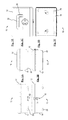
- FIGS. 1A , 1 B, 1 C, 1 D, 1 E and 1 F show rear, front, right-side, left-side, top and bottom views respectively of a secure container according to an embodiment of the present invention
- FIG. 2 shows the secure container of FIGS. 1A-1F in a closed condition
- FIG. 3 shows the container of FIGS. 1A-1F in an open condition
- FIG. 4 shows a removable tray configured to fit within the container of FIGS. 1A-1F according to an embodiment of the present invention
- FIG. 5 shows the removable tray of FIG. 4 installed into the container of FIGS. 1A-1F ;
- FIGS. 6A and 6B show a system for releasably securing the container of FIGS. 1A-1F to a surface according to an embodiment of the present invention
- FIGS. 7 and 8 show a cable lock for use with the container of FIGS. 1A-1F according to an embodiment of the present invention
- FIGS. 9A and 9B show an alarm configured for use with the container of FIGS. 1A-1F according to an embodiment of the present invention
- FIGS. 10 , 11 , 12 , 13 , 14 and 15 show the general arrangement of example configurations of secure containers according to various embodiments of the present invention.
- FIGS. 16 , 17 A and 17 B show a system for releasably securing a container to a surface according to an alternate embodiment of the present invention
- FIGS. 18 , 19 A and 19 B show a system for releasably securing a container to a surface according to another alternate embodiment of the present invention.
- FIGS. 20 , 21 , 22 , 23 A and 23 B show a system for releasably securing a container to a surface according to yet another alternate embodiment of the present invention.
- FIGS. 24 , 25 , and 26 show a system for releasably securing a container to a surface according to yet another alternate embodiment of the present invention.
- FIGS. 1A-1F , 2 and 3 The general arrangement of a secure container 10 is shown in FIGS. 1A-1F , 2 and 3 according to an embodiment of the present invention.
- Container 10 comprises an upper housing portion 12 hingedly attached to a lower housing portion 14 .
- Housing portions 12 , 14 may be made from any suitable materials including, without limitation, ABS or polycarbonate plastic, metal, and composite materials.
- the edges of housing portions 12 , 14 may include a matable tongue and groove.
- an edge of upper housing portion 12 includes a tongue 16 configured to mate to a groove 18 of lower housing portion 14 , although the tongue and groove may be reversed in the housing portions or even omitted if desired.
- a set of legs 20 are positioned proximate each corner of lower housing portion 14 and extend away therefrom. Legs 20 may be formed integral to lower housing portion 14 or may be made separately and attached thereto. Legs 16 may further comprise rubber or felt pads (not shown).
- Upper housing portion 12 includes a stowable handle 22 .
- Handle 22 is pivotably attached to upper housing portion 12 and stows into a cavity 24 generally flush with the upper housing portion in the stowed position.
- Handle 22 may be made from any suitable materials including, without limitation, ABS or polycarbonate plastic, metal, and composite materials.
- a tray 26 is shown in FIG. 4 according to an embodiment of the present invention. Tray 26 is divided into quadrants to facilitate organization of medicines, although a smaller or greater number of dividers may be selected if desired. Tray 26 also includes a pill sorting portion 28 which doubles as a carrying handle for the tray. Tray 26 is configured to be removably installed into container 10 , resting against a bottom 30 of lower housing portion 14 , as shown in FIG. 5 . Tray 26 may be made from any suitable materials including, without limitation, ABS or polycarbonate plastic, metal, and composite materials.
- container 10 includes a combination lock 32 having a user-settable combination.
- a lock tumbler 34 is attached to lower housing portion 14
- a biased lock latch 36 is attached to upper housing portion 12 .
- Latch 36 is lockably engageable to tumbler 34 to selectably secure upper housing portion 12 to lower housing portion 14 .
- upper housing portion 12 includes a first tab 38 having a first opening 40 therethrough.
- lower housing portion 14 includes a second tab 42 having a second opening 44 therethrough, the first and second tabs and openings being generally alignable. Openings 40 , 44 are configured to receive a padlock (not shown) therethrough when container 10 is in a closed condition ( FIG. 2 ) to further, or in the alternative, secure the container by locking together upper housing portion 12 and lower housing portion 14 .
- lower housing portion 14 may further include a set of locking flanges 46 to secure container 10 to a mounting surface 48 such as a wooden or composite shelf.
- Each locking flange 46 fits into an arcuate cavity 50 , which has a depth such that flange 46 is generally flush with bottom 30 of lower housing portion 14 .
- Flange 46 is pivotable about a mounting screw 52 and is selectably positionable to fit through an opening 54 in cavity 50 in an unlocked condition.
- Cavity 50 includes a pair of finger holds 56 and a protrusion 58 to selectably retain flange 46 in a locked condition, as shown in FIG. 6A .
- a bushing 60 may be used to control the spacing of flange 46 from mounting surface 48 , as shown in FIG. 6A .
- flanges 46 are attached to mounting surface 48 with mounting screws 52 and bushings 60 , as generally shown in FIG. 6A .
- Each flange 46 is then pivoted about mounting screw 52 so that the flange is aligned with and fits through corresponding opening 54 into cavity 50 .
- Flange 46 is then pivoted to a locked position past protrusion 58 which provides sufficient interference to retain the flange in the locked position.
- container 10 is secured to mounting surface 48 by flanges 46 .
- locking flanges are accessible only when container 10 is unlocked and open.
- Container 10 may be subsequently detached from mounting surface 48 by unlocking and opening the container, removing tray 26 , then pivoting locking flanges 46 to align with openings 54 .
- Container 10 may then be detached from mounting surface 48 , flanges 46 passing through openings 54 as the container is moved away from the mounting surface.
- Press-fit plugs or the like may optionally be provided to cover the openings 54 when the container 10 is disengaged from the corresponding locking flanges 46 .
- a cable lock 62 may be provided, to which a cable 64 may be attached and secured to a sturdy structure (not shown).
- container 10 may include a security system 66 comprising a transmitter 68 and a receiver 70 .
- Transmitter 66 is installed inside container 10 and is configured to generate an alarm signal if the container is subjected to a shock or is moved.
- the alarm signal may be aural, and/or may include a wireless signal transmitted to receiver 70 .
- Receiver 70 may also be connected to a computer (not shown), in which case a computer program executed by the computer may respond by taking one or more predetermined actions. Predetermined actions may include, without limitation, one or more of sending a text message alert, sending a voicemail alert, sending a paged alert, sending an e-mail alert and recording in the computer memory data relating to the alarm signal.
- container 10 may further include a multi-sheet, tear-away notepad to aid users in monitoring, dispensing and disposing of medications.
- the notepad comprises an inventory log listing such information as the medications contained in container 10 , an inventory of the number of pills, the expected completion date for the medications, dispensing instructions, the number of pills used, and notes regarding the medications. The log thus implements a system for accounting for properly using medications, as well as providing convenient indications regarding when the user should dispose of medications.
- FIGS. 10 through 15 Several example configurations of secure container 10 are shown in FIGS. 10 through 15 according to various embodiments of the present invention. These configurations are for illustrative purposes only and are not intended to be limiting in any way.
- the secure containers 10 of FIGS. 10 through 15 include a key lock 72 which may be substituted for the combination lock 32 described above.
- a system for selectably securing container 10 to a mounting surface 48 is shown in FIGS. 16 , 17 A and 17 B according to an alternate embodiment of the present invention.
- a mount 102 includes a pair of spaced-apart mounting protrusions 104 extending away from a generally planar base 106 .
- Mounting protrusions 104 each include an undercut portion 108 .
- Mount 102 is attached to mounting surface 48 with fasteners such as screws 52 that are inserted through apertures formed in mounting projections 104 and attached to the mounting surface, as shown in FIG. 16 .
- the interior of lower housing portion 14 includes a generally circular recess 110 into which a locking element 112 having a set of locking tabs 114 and a set of opposing members 116 is rotatably attached.
- Recess 110 also includes a set of spaced-apart openings 118 .
- FIGS. 18 , 19 A and 19 B A system for selectably securing container 10 to a mounting surface 48 is shown in FIGS. 18 , 19 A and 19 B according to another alternate embodiment of the present invention.
- Lower housing portion 14 includes an opening 202 generally in the shape of a half-circle.
- a mount 204 also having a general shape of a half-circle, is within the interior of lower housing portion 14 , is oriented opposite opening 202 , and is spaced apart from an interior surface 205 of lower housing portion 14 , forming a cavity 206 .
- a locking element 208 generally having the shape of a half-circle is rotatably attached to mounting surface 48 . Locking element 208 further includes a locking tab 210 .
- container 10 is positioned atop locking element 208 such that the locking element extends through opening 202 ( FIG. 19A ).
- Locking element 208 is then rotated into cavity 206 , a groove or undercut 212 of locking tab 210 engaging mount 204 , thereby securing container 10 to mounting surface 48 ( FIG. 19B ).
- container 10 is positioned over locking element 310 such that the locking element and protrusions 312 extend through slot 304 and into the container ( FIG. 23A ).
- Locking element 310 is then rotated to engage surface 308 , thereby securing container 10 to mounting surface 48 with retaining member 306 .
- the locking mechanism 1501 of a secure container 1500 comprises a fixing component 1510 , a body component 1520 , and a sliding component 1530 .
- Fixing component 1510 is a substantially planar member two mating extrusions 1511 ( a and b ) disposed thereupon.
- Mating extrusions 1511 ( a and b ) are annular, substantially round extrusions having a substantially reduced cross-section upon a medial portion thereof defining shoulders 1512 ( a and b ) thereupon.
- Body component 1520 a substantially embossed portion of face of the casing of a container defining an elevated face 1521 .
- Elevated face 1520 has slide portions 1522 ( a and b ) removed therefrom.
- Slide portions 1522 ( a and b ) comprise elongated apertures operatively configured to define a path for the motion of sliding component 1530 therein.
- Elevated face 1520 has anchor apertures 1523 ( a and b ) removed therefrom and operatively configured to allow passage of the larger portion of mating extrusions 1511 ( a and b ) therethrough.
- Sliding component 1530 is a substantially planar member comprising a primary face 1531 , bearing faces 1532 ( a and b ), and apertures 1533 ( a and b ).
- Primary face 1531 is substantially planar having apertures 1533 ( a and b ) disposed thereupon.
- Apertures 1533 ( a and b ) have a first diameter A and a second diameter B oriented parallel to slide portions 1522 ( a and b ).
- A is configured to allow passage of the larger diameter of mating extrusion 1511 ( a and b ) therethrough, while B is configured to only allow passage of the smaller diameter mating extrusion 1511 ( a and b ) therethrough.
- Bearing faces 1532 ( a and b ) are substantially co-planar faces disposed in substantially parallel relation to primary face 1531 .
- a method of using a locking mechanism 1501 will now be disclosed.
- a user secures a fixing component 1510 to a substantially stationary surface using known methods in the arts, including for instance adhesive, screws, or bolts.
- a secure container 1500 is provided in a first configuration wherein section A of apertures 1533 ( a and b ) is in substantially concentric relation with apertures 1523 ( a and b ).
- a user orients secure container directly over fixing component such that mating extrusions 1511 ( a and b ) are in substantially co-planar and concentric relation with apertures 1523 ( a and b ).
- a user brings secure container 1500 towards fixing component 1510 , thereby extended mating extrusions 1511 ( a and b ) through apertures 1523 ( a and b ).
- a user displaces sliding portion 1530 about its path such that section B of apertures 1533 ( a and b ) comes into substantially concentric relation and with shoulders 1512 ( a and b ) providing mechanical interference thereagainst and consequently temporarily coupling secure container 1500 to fixing component 1510 .
- bushing 60 has a cross-section substantially larger than that of the aperture disposed upon the face of flanges 46 .
- bushing 60 . 1 is a substantially round, annular member having a distal end portion 1601 and a proximal end portion 1602 .
- the outer diameter of proximal end portion 1602 is defined by the diameter of aperture 1604 disposed upon flanges 46 , while the inner diameter of proximal end portion 1602 is defined by the diameter of the shaft of mounting screw 52 .
- the outer diameter of distal end portion 1601 is defined by the diameter of opening 54 , while the inner diameter of distal end portion 1601 is defined by the diameter of the shaft of mounting screw 52 .
- bushing 60 . 2 is substantially planar, annular member having a distal end portion 1701 and a proximal end portion 1702 .
- the outer diameter of proximal end portion 1702 is defined by the diameter of aperture 1604 disposed upon flanges 46 , while the inner diameter of proximal end portion 1702 is defined by the diameter of the shaft of mounting screw 52 .
- the outer diameter of distal end portion 1701 is defined by the shape of opening 54 , while the inner diameter of distal end portion 1701 is defined by the diameter of the shaft of mounting screw 52 .
Abstract
Description
Claims (17)
Priority Applications (1)
| Application Number | Priority Date | Filing Date | Title |
|---|---|---|---|
| US12/880,005 US8800799B1 (en) | 2009-09-11 | 2010-09-10 | Secure container |
Applications Claiming Priority (2)
| Application Number | Priority Date | Filing Date | Title |
|---|---|---|---|
| US24141709P | 2009-09-11 | 2009-09-11 | |
| US12/880,005 US8800799B1 (en) | 2009-09-11 | 2010-09-10 | Secure container |
Publications (1)
| Publication Number | Publication Date |
|---|---|
| US8800799B1 true US8800799B1 (en) | 2014-08-12 |
Family
ID=51267175
Family Applications (1)
| Application Number | Title | Priority Date | Filing Date |
|---|---|---|---|
| US12/880,005 Expired - Fee Related US8800799B1 (en) | 2009-09-11 | 2010-09-10 | Secure container |
Country Status (1)
| Country | Link |
|---|---|
| US (1) | US8800799B1 (en) |
Cited By (9)
| Publication number | Priority date | Publication date | Assignee | Title |
|---|---|---|---|---|
| US20150096910A1 (en) * | 2013-08-07 | 2015-04-09 | Envision Product Development Group, LLC | Gun vault with retractable handle |
| US20160157632A1 (en) * | 2014-12-05 | 2016-06-09 | Michael Nemerouf | Carrier support system |
| US9843849B1 (en) * | 2016-10-25 | 2017-12-12 | Christian Lasnier de Lavalette | Speaker mounting |
| CN108472668A (en) * | 2016-01-15 | 2018-08-31 | 3M创新有限公司 | The button latch fluid connector of pistol |
| US10406986B2 (en) * | 2015-07-31 | 2019-09-10 | Bombardier Recreational Products Inc. | Storage container for a vehicle |
| US10758037B2 (en) * | 2016-09-16 | 2020-09-01 | Oahwip B.V. | Quick assembly desk |
| US11217337B2 (en) * | 2013-03-15 | 2022-01-04 | Intent Solutions, Inc. | Systems, methods, and apparatuses for securely dispensing one or more prescribed substances to a securely identified intended user |
| US11378117B1 (en) * | 2020-01-28 | 2022-07-05 | Benjamin Andrew Galjour | Method and apparatus for attaching legs to furniture |
| US11473361B1 (en) * | 2019-06-21 | 2022-10-18 | Urban Sales, LLC | Safe |
Citations (38)
| Publication number | Priority date | Publication date | Assignee | Title |
|---|---|---|---|---|
| US72283A (en) | 1867-12-17 | William gardner | ||
| US534012A (en) | 1895-02-12 | Phqto-utmo | ||
| US963883A (en) | 1910-04-25 | 1910-07-12 | John W Farley | Portable safe-deposit receptacle. |
| US1082790A (en) | 1912-09-27 | 1913-12-30 | Hiram Beshore | Safe-deposit receptacle. |
| US1203282A (en) | 1914-07-25 | 1916-10-31 | Gustave Georg Uth | Safety-box for valuables. |
| US1472701A (en) | 1921-11-07 | 1923-10-30 | Vogelaar Anthony William | Tool box |
| US1652619A (en) | 1927-02-17 | 1927-12-13 | A Fiss Company | Tool box |
| US1796502A (en) * | 1928-06-22 | 1931-03-17 | Boucher Alexander Raymond | Carrying case equipped with lock-controlled attaching means |
| US1805759A (en) | 1928-08-03 | 1931-05-19 | Harry B Chamberlain | Safe |
| US1916509A (en) | 1932-01-22 | 1933-07-04 | United Metal Box Co Inc | Wall cabinet mounting |
| US2353452A (en) | 1943-04-15 | 1944-07-11 | Arthur W Fruh | Burglar alarm control box |
| US2754498A (en) | 1954-04-29 | 1956-07-10 | Louise K Lavelle | Alarm device for suspended articles |
| US2791976A (en) | 1953-03-23 | 1957-05-14 | William F Kruschwitz | Collection device |
| US3347069A (en) | 1965-07-09 | 1967-10-17 | Jr Richard M Hollingshead | Security container |
| US4029370A (en) | 1974-10-02 | 1977-06-14 | Olivier Ziegel | Portable safe |
| US4143927A (en) | 1977-10-21 | 1979-03-13 | Market Forge, A Division Of Beatrice Foods Co. | Cassette locking device |
| US4195579A (en) * | 1978-12-11 | 1980-04-01 | Doyel John S | Portable safe |
| US4244304A (en) | 1979-11-06 | 1981-01-13 | Read Ronald H | Security box and mounting plate |
| US4249684A (en) | 1979-03-22 | 1981-02-10 | Le Roy Dombeck | Removably anchored box |
| US4325531A (en) | 1980-02-11 | 1982-04-20 | Omholt Bruce D | Apparatus for removably securing a container to a carrier rack |
| US4457240A (en) | 1982-06-25 | 1984-07-03 | Hungerford Robert E | Hand held and/or hard mounted weatherproof portable travel safe for full time protection of essential travel valuables |
| US4462317A (en) | 1982-09-29 | 1984-07-31 | Lloyd Franko | Lock boxes |
| US4474116A (en) | 1983-05-17 | 1984-10-02 | Castenada Jr Ray | Safe box with anchor chain |
| US4493268A (en) | 1983-05-10 | 1985-01-15 | Karl Sidler | Safe keeping box assembly |
| US4532783A (en) | 1982-12-27 | 1985-08-06 | Maurice Thomas A | Double lock lock box |
| US4579214A (en) | 1984-02-13 | 1986-04-01 | Volk Russell D | Coin vault for a car wash or the like |
| US4728017A (en) | 1987-05-22 | 1988-03-01 | Mullican Randall J | Clamp-on storage container for pickup trucks |
| US4821538A (en) | 1987-09-04 | 1989-04-18 | Gray Eric A | Security-providing container device |
| US4926762A (en) | 1989-10-10 | 1990-05-22 | Paul Clarence A | Security safes for vehicles |
| US4951577A (en) | 1989-01-11 | 1990-08-28 | Bentley James K | Wall safe assembly |
| US4953374A (en) | 1986-12-22 | 1990-09-04 | Wiebe Jacob R | Secure locking mechanism |
| US4987836A (en) * | 1988-11-04 | 1991-01-29 | Owen John S | Safes |
| US5170907A (en) * | 1990-11-13 | 1992-12-15 | Nobuyo Sakai | Personal security case |
| US5232303A (en) * | 1990-05-22 | 1993-08-03 | Wilkhahn Wilkening + Hahne Gmbh + Co. | Connecting arrangement |
| US5621387A (en) | 1995-08-08 | 1997-04-15 | Elk Products, Inc. | Box |
| US5651595A (en) * | 1996-02-13 | 1997-07-29 | Willis; Thomas T. | Storage cabinet |
| US5688030A (en) * | 1996-08-09 | 1997-11-18 | Dell Usa Lp | Electronic equipment enclosure with support members |
| US5870910A (en) | 1996-12-02 | 1999-02-16 | Block And Company, Inc. | Lock-down security box |
-
2010
- 2010-09-10 US US12/880,005 patent/US8800799B1/en not_active Expired - Fee Related
Patent Citations (38)
| Publication number | Priority date | Publication date | Assignee | Title |
|---|---|---|---|---|
| US72283A (en) | 1867-12-17 | William gardner | ||
| US534012A (en) | 1895-02-12 | Phqto-utmo | ||
| US963883A (en) | 1910-04-25 | 1910-07-12 | John W Farley | Portable safe-deposit receptacle. |
| US1082790A (en) | 1912-09-27 | 1913-12-30 | Hiram Beshore | Safe-deposit receptacle. |
| US1203282A (en) | 1914-07-25 | 1916-10-31 | Gustave Georg Uth | Safety-box for valuables. |
| US1472701A (en) | 1921-11-07 | 1923-10-30 | Vogelaar Anthony William | Tool box |
| US1652619A (en) | 1927-02-17 | 1927-12-13 | A Fiss Company | Tool box |
| US1796502A (en) * | 1928-06-22 | 1931-03-17 | Boucher Alexander Raymond | Carrying case equipped with lock-controlled attaching means |
| US1805759A (en) | 1928-08-03 | 1931-05-19 | Harry B Chamberlain | Safe |
| US1916509A (en) | 1932-01-22 | 1933-07-04 | United Metal Box Co Inc | Wall cabinet mounting |
| US2353452A (en) | 1943-04-15 | 1944-07-11 | Arthur W Fruh | Burglar alarm control box |
| US2791976A (en) | 1953-03-23 | 1957-05-14 | William F Kruschwitz | Collection device |
| US2754498A (en) | 1954-04-29 | 1956-07-10 | Louise K Lavelle | Alarm device for suspended articles |
| US3347069A (en) | 1965-07-09 | 1967-10-17 | Jr Richard M Hollingshead | Security container |
| US4029370A (en) | 1974-10-02 | 1977-06-14 | Olivier Ziegel | Portable safe |
| US4143927A (en) | 1977-10-21 | 1979-03-13 | Market Forge, A Division Of Beatrice Foods Co. | Cassette locking device |
| US4195579A (en) * | 1978-12-11 | 1980-04-01 | Doyel John S | Portable safe |
| US4249684A (en) | 1979-03-22 | 1981-02-10 | Le Roy Dombeck | Removably anchored box |
| US4244304A (en) | 1979-11-06 | 1981-01-13 | Read Ronald H | Security box and mounting plate |
| US4325531A (en) | 1980-02-11 | 1982-04-20 | Omholt Bruce D | Apparatus for removably securing a container to a carrier rack |
| US4457240A (en) | 1982-06-25 | 1984-07-03 | Hungerford Robert E | Hand held and/or hard mounted weatherproof portable travel safe for full time protection of essential travel valuables |
| US4462317A (en) | 1982-09-29 | 1984-07-31 | Lloyd Franko | Lock boxes |
| US4532783A (en) | 1982-12-27 | 1985-08-06 | Maurice Thomas A | Double lock lock box |
| US4493268A (en) | 1983-05-10 | 1985-01-15 | Karl Sidler | Safe keeping box assembly |
| US4474116A (en) | 1983-05-17 | 1984-10-02 | Castenada Jr Ray | Safe box with anchor chain |
| US4579214A (en) | 1984-02-13 | 1986-04-01 | Volk Russell D | Coin vault for a car wash or the like |
| US4953374A (en) | 1986-12-22 | 1990-09-04 | Wiebe Jacob R | Secure locking mechanism |
| US4728017A (en) | 1987-05-22 | 1988-03-01 | Mullican Randall J | Clamp-on storage container for pickup trucks |
| US4821538A (en) | 1987-09-04 | 1989-04-18 | Gray Eric A | Security-providing container device |
| US4987836A (en) * | 1988-11-04 | 1991-01-29 | Owen John S | Safes |
| US4951577A (en) | 1989-01-11 | 1990-08-28 | Bentley James K | Wall safe assembly |
| US4926762A (en) | 1989-10-10 | 1990-05-22 | Paul Clarence A | Security safes for vehicles |
| US5232303A (en) * | 1990-05-22 | 1993-08-03 | Wilkhahn Wilkening + Hahne Gmbh + Co. | Connecting arrangement |
| US5170907A (en) * | 1990-11-13 | 1992-12-15 | Nobuyo Sakai | Personal security case |
| US5621387A (en) | 1995-08-08 | 1997-04-15 | Elk Products, Inc. | Box |
| US5651595A (en) * | 1996-02-13 | 1997-07-29 | Willis; Thomas T. | Storage cabinet |
| US5688030A (en) * | 1996-08-09 | 1997-11-18 | Dell Usa Lp | Electronic equipment enclosure with support members |
| US5870910A (en) | 1996-12-02 | 1999-02-16 | Block And Company, Inc. | Lock-down security box |
Cited By (13)
| Publication number | Priority date | Publication date | Assignee | Title |
|---|---|---|---|---|
| US11217337B2 (en) * | 2013-03-15 | 2022-01-04 | Intent Solutions, Inc. | Systems, methods, and apparatuses for securely dispensing one or more prescribed substances to a securely identified intended user |
| US20150096910A1 (en) * | 2013-08-07 | 2015-04-09 | Envision Product Development Group, LLC | Gun vault with retractable handle |
| US20160157632A1 (en) * | 2014-12-05 | 2016-06-09 | Michael Nemerouf | Carrier support system |
| US10800338B2 (en) * | 2015-07-31 | 2020-10-13 | Bombardier Recreational Products Inc. | Storage container for a vehicle |
| US10406986B2 (en) * | 2015-07-31 | 2019-09-10 | Bombardier Recreational Products Inc. | Storage container for a vehicle |
| US20190344722A1 (en) * | 2015-07-31 | 2019-11-14 | Bombardier Recreational Products Inc. | Storage container for a vehicle |
| JP2019504753A (en) * | 2016-01-15 | 2019-02-21 | スリーエム イノベイティブ プロパティズ カンパニー | Button lock fluid connector for handheld spray gun |
| US20190176174A1 (en) * | 2016-01-15 | 2019-06-13 | 3M Innovative Properties Company | Button-lock fluid connector for hand-held spray guns |
| CN108472668A (en) * | 2016-01-15 | 2018-08-31 | 3M创新有限公司 | The button latch fluid connector of pistol |
| US10758037B2 (en) * | 2016-09-16 | 2020-09-01 | Oahwip B.V. | Quick assembly desk |
| US9843849B1 (en) * | 2016-10-25 | 2017-12-12 | Christian Lasnier de Lavalette | Speaker mounting |
| US11473361B1 (en) * | 2019-06-21 | 2022-10-18 | Urban Sales, LLC | Safe |
| US11378117B1 (en) * | 2020-01-28 | 2022-07-05 | Benjamin Andrew Galjour | Method and apparatus for attaching legs to furniture |
Similar Documents
| Publication | Publication Date | Title |
|---|---|---|
| US8800799B1 (en) | Secure container | |
| US8201423B1 (en) | Combination and key operated locks with indicators | |
| US6237375B1 (en) | Lap top lock | |
| US7204106B2 (en) | Portable electronic device physical security | |
| US8539799B2 (en) | Combination lock | |
| US5687592A (en) | Mechanical lock for a removable hard disk drive and a removable memory card | |
| US3934434A (en) | Key safe apparatus | |
| US20040069030A1 (en) | Side bar type cylinder lock with variable key code | |
| US20070289342A1 (en) | Electronic restraint system | |
| US20060207301A1 (en) | Interlocked double-unlockable lock apparatus | |
| JPH06511297A (en) | Anti-theft device, locking device and anti-theft method | |
| US11591822B2 (en) | Multi-key lock core | |
| JPH07324546A (en) | Latch system and storage case having said system | |
| WO2010065732A3 (en) | Locking device for tote bin | |
| US20160201379A1 (en) | Concealed wall safe with enhanced locking mechanism | |
| US20090151402A1 (en) | Combination padlock with a chamber | |
| US10370889B2 (en) | Vehicle security box | |
| US6530248B1 (en) | Lock device | |
| GB2037257A (en) | Safe | |
| US20180238079A1 (en) | Security Key Hasp | |
| US20080116216A1 (en) | Container | |
| WO2020029124A1 (en) | Sliding lock assembly, method, and system | |
| EP2511457B1 (en) | Locking device, particularly for containers of the type of suitcases, trunks and the like | |
| EP3483843A1 (en) | System for storing at least one item, for a vehicle | |
| US7296446B1 (en) | Lock assembly |
Legal Events
| Date | Code | Title | Description |
|---|---|---|---|
| FEPP | Fee payment procedure |
Free format text: MAINTENANCE FEE REMINDER MAILED (ORIGINAL EVENT CODE: REM.) |
|
| LAPS | Lapse for failure to pay maintenance fees |
Free format text: PATENT EXPIRED FOR FAILURE TO PAY MAINTENANCE FEES (ORIGINAL EVENT CODE: EXP.); ENTITY STATUS OF PATENT OWNER: SMALL ENTITY |
|
| STCH | Information on status: patent discontinuation |
Free format text: PATENT EXPIRED DUE TO NONPAYMENT OF MAINTENANCE FEES UNDER 37 CFR 1.362 |
|
| FP | Lapsed due to failure to pay maintenance fee |
Effective date: 20180812 |
|
| AS | Assignment |
Owner name: FLAMBEAU, INC., WISCONSIN Free format text: ASSIGNMENT OF ASSIGNORS INTEREST;ASSIGNORS:HAWKER, CHRIS;MORELAND, JESSICA;TRUNEK, CHRIS;SIGNING DATES FROM 20140911 TO 20141002;REEL/FRAME:049570/0546 |
|
| FEPP | Fee payment procedure |
Free format text: PETITION RELATED TO MAINTENANCE FEES FILED (ORIGINAL EVENT CODE: PMFP); ENTITY STATUS OF PATENT OWNER: SMALL ENTITY |
|
| FEPP | Fee payment procedure |
Free format text: PETITION RELATED TO MAINTENANCE FEES DISMISSED (ORIGINAL EVENT CODE: PMFS); ENTITY STATUS OF PATENT OWNER: SMALL ENTITY |
|
| FEPP | Fee payment procedure |
Free format text: PETITION RELATED TO MAINTENANCE FEES FILED (ORIGINAL EVENT CODE: PMFP); ENTITY STATUS OF PATENT OWNER: SMALL ENTITY Free format text: SURCHARGE, PETITION TO ACCEPT PYMT AFTER EXP, UNINTENTIONAL (ORIGINAL EVENT CODE: M1558); ENTITY STATUS OF PATENT OWNER: SMALL ENTITY |
|
| MAFP | Maintenance fee payment |
Free format text: PAYMENT OF MAINTENANCE FEE, 4TH YEAR, LARGE ENTITY (ORIGINAL EVENT CODE: M1551); ENTITY STATUS OF PATENT OWNER: SMALL ENTITY Year of fee payment: 4 |
|
| PRDP | Patent reinstated due to the acceptance of a late maintenance fee |
Effective date: 20200408 |
|
| FEPP | Fee payment procedure |
Free format text: PETITION RELATED TO MAINTENANCE FEES GRANTED (ORIGINAL EVENT CODE: PMFG); ENTITY STATUS OF PATENT OWNER: SMALL ENTITY |
|
| STCF | Information on status: patent grant |
Free format text: PATENTED CASE |
|
| FEPP | Fee payment procedure |
Free format text: MAINTENANCE FEE REMINDER MAILED (ORIGINAL EVENT CODE: REM.); ENTITY STATUS OF PATENT OWNER: SMALL ENTITY |
|
| LAPS | Lapse for failure to pay maintenance fees |
Free format text: PATENT EXPIRED FOR FAILURE TO PAY MAINTENANCE FEES (ORIGINAL EVENT CODE: EXP.); ENTITY STATUS OF PATENT OWNER: SMALL ENTITY |
|
| STCH | Information on status: patent discontinuation |
Free format text: PATENT EXPIRED DUE TO NONPAYMENT OF MAINTENANCE FEES UNDER 37 CFR 1.362 |
|
| FP | Lapsed due to failure to pay maintenance fee |
Effective date: 20220812 |