US8769390B2 - Apparatus and method for processing operations in parallel using a single instruction multiple data processor - Google Patents
Apparatus and method for processing operations in parallel using a single instruction multiple data processor Download PDFInfo
- Publication number
- US8769390B2 US8769390B2 US13/364,687 US201213364687A US8769390B2 US 8769390 B2 US8769390 B2 US 8769390B2 US 201213364687 A US201213364687 A US 201213364687A US 8769390 B2 US8769390 B2 US 8769390B2
- Authority
- US
- United States
- Prior art keywords
- input data
- column
- parallel
- source nodes
- path
- Prior art date
- Legal status (The legal status is an assumption and is not a legal conclusion. Google has not performed a legal analysis and makes no representation as to the accuracy of the status listed.)
- Expired - Fee Related, expires
Links
- 238000012545 processing Methods 0.000 title claims abstract description 129
- 238000000034 method Methods 0.000 title abstract description 18
- 238000003672 processing method Methods 0.000 claims description 13
- 230000015654 memory Effects 0.000 description 17
- 238000010586 diagram Methods 0.000 description 15
- 238000013500 data storage Methods 0.000 description 11
- 230000008569 process Effects 0.000 description 8
- 230000003287 optical effect Effects 0.000 description 3
- 230000004044 response Effects 0.000 description 3
- 238000004891 communication Methods 0.000 description 2
- 238000012986 modification Methods 0.000 description 2
- 230000004048 modification Effects 0.000 description 2
- 230000008901 benefit Effects 0.000 description 1
- 230000001413 cellular effect Effects 0.000 description 1
- 238000010276 construction Methods 0.000 description 1
- 238000012937 correction Methods 0.000 description 1
- 238000005516 engineering process Methods 0.000 description 1
- 230000006870 function Effects 0.000 description 1
- 239000007787 solid Substances 0.000 description 1
Images


Classifications
-
- G—PHYSICS
- G06—COMPUTING; CALCULATING OR COUNTING
- G06F—ELECTRIC DIGITAL DATA PROCESSING
- G06F9/00—Arrangements for program control, e.g. control units
- G06F9/06—Arrangements for program control, e.g. control units using stored programs, i.e. using an internal store of processing equipment to receive or retain programs
- G06F9/30—Arrangements for executing machine instructions, e.g. instruction decode
- G06F9/38—Concurrent instruction execution, e.g. pipeline, look ahead
-
- G—PHYSICS
- G06—COMPUTING; CALCULATING OR COUNTING
- G06F—ELECTRIC DIGITAL DATA PROCESSING
- G06F15/00—Digital computers in general; Data processing equipment in general
- G06F15/76—Architectures of general purpose stored program computers
- G06F15/80—Architectures of general purpose stored program computers comprising an array of processing units with common control, e.g. single instruction multiple data processors
- G06F15/8053—Vector processors
- G06F15/8076—Details on data register access
-
- G—PHYSICS
- G06—COMPUTING; CALCULATING OR COUNTING
- G06F—ELECTRIC DIGITAL DATA PROCESSING
- G06F9/00—Arrangements for program control, e.g. control units
- G06F9/06—Arrangements for program control, e.g. control units using stored programs, i.e. using an internal store of processing equipment to receive or retain programs
- G06F9/30—Arrangements for executing machine instructions, e.g. instruction decode
- G06F9/30003—Arrangements for executing specific machine instructions
- G06F9/30007—Arrangements for executing specific machine instructions to perform operations on data operands
- G06F9/30018—Bit or string instructions
-
- H—ELECTRICITY
- H03—ELECTRONIC CIRCUITRY
- H03M—CODING; DECODING; CODE CONVERSION IN GENERAL
- H03M13/00—Coding, decoding or code conversion, for error detection or error correction; Coding theory basic assumptions; Coding bounds; Error probability evaluation methods; Channel models; Simulation or testing of codes
- H03M13/37—Decoding methods or techniques, not specific to the particular type of coding provided for in groups H03M13/03 - H03M13/35
- H03M13/39—Sequence estimation, i.e. using statistical methods for the reconstruction of the original codes
- H03M13/41—Sequence estimation, i.e. using statistical methods for the reconstruction of the original codes using the Viterbi algorithm or Viterbi processors
- H03M13/4107—Sequence estimation, i.e. using statistical methods for the reconstruction of the original codes using the Viterbi algorithm or Viterbi processors implementing add, compare, select [ACS] operations
-
- H—ELECTRICITY
- H03—ELECTRONIC CIRCUITRY
- H03M—CODING; DECODING; CODE CONVERSION IN GENERAL
- H03M13/00—Coding, decoding or code conversion, for error detection or error correction; Coding theory basic assumptions; Coding bounds; Error probability evaluation methods; Channel models; Simulation or testing of codes
- H03M13/37—Decoding methods or techniques, not specific to the particular type of coding provided for in groups H03M13/03 - H03M13/35
- H03M13/39—Sequence estimation, i.e. using statistical methods for the reconstruction of the original codes
- H03M13/41—Sequence estimation, i.e. using statistical methods for the reconstruction of the original codes using the Viterbi algorithm or Viterbi processors
- H03M13/4161—Sequence estimation, i.e. using statistical methods for the reconstruction of the original codes using the Viterbi algorithm or Viterbi processors implementing path management
- H03M13/4169—Sequence estimation, i.e. using statistical methods for the reconstruction of the original codes using the Viterbi algorithm or Viterbi processors implementing path management using traceback
-
- H—ELECTRICITY
- H03—ELECTRONIC CIRCUITRY
- H03M—CODING; DECODING; CODE CONVERSION IN GENERAL
- H03M13/00—Coding, decoding or code conversion, for error detection or error correction; Coding theory basic assumptions; Coding bounds; Error probability evaluation methods; Channel models; Simulation or testing of codes
- H03M13/65—Purpose and implementation aspects
- H03M13/6561—Parallelized implementations
Definitions
- SIMD Single Instruction Multiple Data
- SIMD Single Instruction Multiple Data
- SIMD is a class of parallel computing for processing multiple pieces of data using a single instruction.
- SIMD enables a plurality of operation apparatuses to simultaneously process multiple data by applying the same operation or a similar operation to the multiple data.
- SIMD may be used in a vector processor.
- a decoder such as a Viterbi decoder may be included in a processor.
- a Viterbi decoder uses a Viterbi algorithm to decode a bitstream that has been encoded using forward error correction.
- Viterbi decoding typically includes three operations, for example, a Branch Metric Computation (BMC) operation, an Add-Compare-Select (ACS) operation, and a Traceback (TB) operation.
- BMC Branch Metric Computation
- ACS Add-Compare-Select
- TB Traceback
- a parallel operation processing apparatus including a parallel operator configured to calculate a path value of source nodes in a current column, and to determine input data and at least one source node in a previous column, the input data corresponding to a path selected using the path value, and a data arrangement unit configured to arrange first input data of the source nodes in the current column, based on an order of second input data of the at least one source node in the previous column, wherein the parallel operator combines the arranged first input data with the second input data, based on a register processing unit, and stores the combined input data in a parallel register unit.
- the parallel operator may be configured to perform a bit shift operation on the second input data, combine the arranged first input data with the second input data on which the bit shift operation is performed, and store the combined input data.
- the data arrangement unit may be configured to arrange the first input data such that the first input data is physically concatenated with the second input data.
- the parallel operator may be configured to store, for every register processing unit, index information indicating the at least one source node in the previous column.
- the index information may comprise information about source nodes in a last column of a previous register that are logically connected to source nodes in a first column of a current register, based on the selected path.
- the parallel operator may be further configured to determine a minimum path value among the plurality of path values, and store the determined minimum path value in the parallel register unit by overwriting the determined minimum path value to a location in which a minimum path value in the at least one source node in the previous column is stored.
- the parallel operator may be configured to calculate path values in source nodes in a last column, and trace back input data of source nodes in previous columns that are connected to a final source node corresponding to a minimum path value among the calculated path values.
- the parallel operator may be configured to acquire input data corresponding to source nodes connected to the final source node by repeating the tracing from the source nodes in the last column to source nodes in a first column.
- the parallel operator may be configured to calculate the path value by accumulating, based on the current column, metrics of source nodes computed for each column by performing Viterbi decoding.
- the at least one source node in the previous column may be logically connected to each of the source nodes in the current column based on the selected path.
- a parallel operation processing method including calculating a path value of source nodes in a current column, determining input data and at least one source node in a previous column, the input data corresponding to a path selected using the path value, arranging first input data of the source nodes in the current column, based on an order of second input data of the at least one source node in the previous column, and combining the arranged first input data with the second input data, based on a register processing unit, and storing the combined input data.
- the combining may comprise performing a bit shift operation on the second input data, combining the arranged first input data with the second input data on which the bit shift operation is performed, and storing the combined input data in a parallel register unit.
- the arranging may comprise arranging the first input data such that the first input data is physically concatenated with the second input data.
- the combining may comprise storing, for every register processing unit, index information indicating the at least one source node in the previous column.
- the index information may comprise information about source nodes in a last column of a previous register that are logically connected to source nodes in a first column of a current register based on the selected path.
- the determining may comprise, if a plurality of path values exist in each of the source nodes in the current column, determining a minimum path value among the plurality of path values, and the combining comprises storing the determined minimum path value in the parallel register unit by overwriting the determined minimum path value to a location in which a minimum path value in the at least one source node in the previous column is stored.
- the calculating may comprise calculating path values in source nodes of a last column, and tracing back input data of source nodes of previous columns that are connected to a final source node corresponding to a minimum path value among the calculated path values.
- the calculating may comprise acquiring input data corresponding to source nodes connected to the final source node by repeating the tracing from the source nodes in the last column to source nodes in a first column.
- the path value may be calculated by accumulating, based on the current column, metrics of source nodes computed for each column by performing Viterbi decoding.
- the at least one source node in the previous column may be logically connected to each of the source nodes in the current column based on the selected path.
- a computer-readable storage medium having stored therein program instructions to cause a computer to implement a parallel operation processing method including calculating a path value of source nodes in a current column, determining input data and at least one source node in a previous column, the input data corresponding to a path selected using the path value, arranging first input data of the source nodes in the current column, based on an order of second input data of the at least one source node in the previous column, and combining the arranged first input data with the second input data, based on a register processing unit, and storing the combined input data.
- FIG. 1 is a diagram illustrating an example of a parallel operation processing apparatus including a Single Instruction Multiple Data (SIMD) processor.
- SIMD Single Instruction Multiple Data
- FIG. 2 is a diagram illustrating an example of a parallel register unit.
- FIG. 3 is a diagram illustrating an example of processing Branch Metric Computation (BMC) operations in parallel.
- BMC Branch Metric Computation
- FIG. 4 is a diagram illustrating an example of processing Add-Compare-Select (ACS) operations in parallel.
- ACS Add-Compare-Select
- FIG. 5 is a diagram illustrating an example of a Viterbi algorithm using a trellis diagram.
- FIG. 6 is a diagram illustrating examples of components used to perform an ACS operation from among components of a parallel operation processing apparatus.
- FIG. 7 is a diagram illustrating an example of arranging input data of source nodes in a current column.
- FIG. 8 is a diagram illustrating an example of a bit shift operation performed in a parallel operation processing apparatus.
- FIG. 9 is a diagram illustrating an example of processing Traceback (TB) operations in parallel.
- FIG. 10 is a flowchart illustrating an example of a method for processing Viterbi decoding in parallel using a SIMD processor.
- FIG. 11 is a diagram illustrating an example of processing an operation in response to an input of two pieces of data.
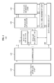
- FIG. 1 illustrates an example of a parallel operation processing apparatus including a Single Instruction Multiple Data (SIMD) processor.
- the parallel operation processing apparatus may be included in a terminal, for example, a computer, a mobile phone, a tablet, a game console, a home appliance, and the like.
- parallel operation processing apparatus 100 includes an instruction storage unit 110 , a controller 120 , a scalar operator 130 , a scalar register unit 140 , a parallel operator 150 , a parallel register unit 160 , a data arrangement unit 170 , and a data storage unit 180 .
- the instruction storage unit 110 may store instructions used to control various operations performed in the parallel operation processing apparatus 100 .
- the instruction storage unit 110 may store instructions associated with operations for processing Viterbi decoding such as a Branch Metric Computation (BMC) instruction, an Add-Compare-to Select (ACS) instruction, a Traceback (TB) instruction, and the like.
- BMC Branch Metric Computation
- ACS Add-Compare-to Select
- TB Traceback
- the BMC instruction may be used to compute branch metrics.
- the ACS instruction may be used to compare path metrics (hereinafter, referred to as “path values”) for each node which are generated by accumulating the computed branch metrics, and to select a path metric from among the path metrics.
- the TB instruction may be used to trace back source nodes in previous columns that are connected to a node corresponding to a minimum path metric among path metrics of source nodes that are included in a last column.
- the controller 120 may generate a control signal corresponding to an instruction stored in the instruction storage unit 110 .
- the controller 120 may generate a control signal to control the parallel operation processing apparatus 100 that includes the SIMD processor.
- the data storage unit 180 may store input data that is used to perform Viterbi decoding, and operation result data that is obtained as a result of the Viterbi decoding.
- the data storage unit 180 may store a BMC operation result that is obtained by the BMC operation, an ACS operation result that is obtained by the ACS operation, and a TB operation result that is obtained by the TB operation.
- the scalar operator 130 may process an operation, for example, an operation that is difficult or less efficient to process in parallel.
- the scalar register unit 140 may include registers that are used to perform an operation by the scalar operator 130 .
- the parallel operator 150 may process an operation to process a plurality of pieces of data using a single instruction.
- the parallel operator 150 may be a SIMD operator.
- the parallel register unit 160 may include registers that are used to perform an operation by the parallel operator 150 .
- the parallel register unit 160 may be referred to as a SIMD register unit.
- the data arrangement unit 170 may arrange the results of operations that are processed by the parallel operator 150 .
- the data arrangement unit 170 may arrange ACS operation results that are obtained by the ACS operation.
- the data arrangement unit 170 may arrange operation results associated with a current column, so that the arranged operation results may be used as inputs of a next column
- the parallel operator 150 may combine the arranged operation results with operation results that are associated with a previous column, and may store the combined operation results in the parallel register unit 160 .
- FIG. 2 illustrates an example of the parallel register unit, for example, the parallel register unit 160 of FIG. 1 .
- the parallel register unit includes a plurality of vector registers such as vector registers VR 0 through VR m-1 .
- a parallel operator includes a plurality of Arithmetic Logical Units (ALUs), for example ALU 0 through ALU n-1 .
- the plurality of ALUs may correspond to a number of source nodes, for example source nodes SN 0 through SN n-1 .
- source nodes SN 0 through SN n-1 For example, if “N ⁇ 1” source nodes exist, the parallel operator 150 may include “N ⁇ 1” ALUs.
- An ALU may read two pieces of input data from among pieces of input data that are stored in the parallel register unit, may perform an operation on the read input data, and may store a single operation result in the parallel register unit.
- an ALU 0 201 may read input data stored in a vector register VR o 202 , and input data stored in a vector register VR 1 203 .
- the ALU 0 201 may perform an operation for Viterbi decoding of the two pieces of read input data, and may obtain a single operation result. Subsequently, the ALU 0 201 may store the obtained operation result in one of the vector registers.
- the ALU 0 201 may store the obtained operation result in an unnecessary space of the vector register VR 0 202 , or in an empty space among vector registers VR 2 through VR m-1 .
- FIG. 3 illustrates an example of processing BMC operations in parallel.
- the BMC operations may be performed by the parallel operator 150 of FIG. 1 .
- a parallel operation processing apparatus may output a result R 0 that is obtained by calculating an absolute value of a difference between data A 0 and B 0 .
- the parallel operation processing apparatus may perform, in parallel, BMC operations on all “n” source nodes that are included in a current column.
- the BMC operations may be simultaneously performed in source nodes in the current column.
- the parallel operation processing apparatus may simultaneously perform BMC operations BMC 0 through BMC n , and may output results as R 0 through R n .
- FIG. 4 illustrates an example of processing ACS operations in parallel.
- the ACS operations may be performed by the parallel operator 150 of FIG. 1 .
- a parallel operation processing apparatus may select a path value from among path values that are obtained by adding a metric of each of nodes in a current column to a path value of each of nodes in a previous column, and may output the selected path value.
- a parallel operation processing apparatus may add metric 0 corresponding to the path (0) 503 to a path value of a source node “a” in a column (3) 501 (a previous column), and may add metric 1 corresponding to the path (1) 504 to a path value of a source node “c” in the column (3) 501 . Subsequently, the parallel operation processing apparatus may compare the two result values.
- the metric 0 and metric 1 may respectively correspond to a path-metric 0 and path-metric 1 of FIG. 4
- the path value of the source node “a” and path value of the source node “c” may respectively correspond to BMC 0 and BMC 1 of FIG. 4 .
- the parallel operation processing apparatus may output the smaller value of the two result values as a path value 401 of the current column, may select a path corresponding to the path value 401 , and may output input data 403 corresponding to the selected path.
- the parallel operation processing apparatus may also output index information 402 that indicates a source node in a previous column that is connected to a source node in the current column based on the selected path.
- the parallel operation processing apparatus may output “8” as the path value 401 .
- the parallel operation processing apparatus may select the path (1) 504 corresponding to the path value of “8” from between the path (0) 503 and path (1) 504 .
- the parallel operation processing apparatus may output the index information 402 indicating that the source node “a” in the column (4) 502 is logically connected to the source node “c” in the column (3) 501 based on the selected path (1) 504 .
- the parallel operation processing apparatus may output the input data 403 corresponding to the selected path (1) 504 .
- the parallel operation processing apparatus may output a path value of the current column, index information, and input data, for each of the source nodes included in the current column, through the ACS operations.
- FIG. 6 illustrates examples of components used to perform an ACS operation from among components of a parallel operation processing apparatus.
- parallel operation processing apparatus 600 includes a parallel operator 601 , a parallel register unit 602 , a data arrangement unit 603 , and a data storage unit 604 .
- the parallel operator 601 may calculate a path value of each of the source nodes included in a current column.
- the path value refers to a value that is obtained by accumulating, based on a current column, metrics of source nodes computed for each column
- the path value may indicate a value that is obtained by adding metrics in source nodes in each of the previous columns to metrics in source nodes in the current column, based on the source nodes in the current column.
- the path value may refer to, for example, a value that is obtained by accumulating Hamming distances in Viterbi decoding.
- the parallel operator 601 may select a path using the calculated path values. For example, if a plurality of path values are calculated, the parallel operator 601 may determine a smallest path value among the plurality of path values as a minimum path value, and may select a path corresponding to the minimum path value. Subsequently, the parallel operator 601 may store the minimum path value in the parallel register unit 602 by overwriting the minimum path value to a location in which a minimum path value in the source nodes in the previous column is stored.
- the parallel operator 601 may determine input data corresponding to the selected path, and may determine source nodes in the previous column based on the selected path. For example, the source nodes in the previous column may be logically connected to the source nodes in the current column, based on the selected path. Accordingly, the parallel operator 601 may determine index information indicating the source nodes in the previous column.
- the data arrangement unit 603 may determine an order of input data of each of the source nodes in the current column, based on an order of input data of each of the source nodes in the previous column
- the input data of each of the source nodes in the current column is referred to as input data for the current column
- the input data of each of the source nodes in the previous column is referred to as input data for the previous column.
- the data arrangement unit 603 may arrange the input data for the current column For example, the data arrangement unit 603 may arrange the input data for the current column such that the input data for the current column is physically concatenated with the input data for the previous column As described herein, the source nodes in the previous column may be logically connected to the source nodes in the current column.
- FIG. 7 illustrates an example of arranging input data of source nodes.
- the data arrangement unit 603 may arrange, in a vector register, input data corresponding to a source node 0 in the current column 701 , so that the input data corresponding to the source node 0 is physically concatenated with input data corresponding to a source node 0 in the previous column 702 .
- the source node 0 in the previous column 702 may be logically connected to the source node 0 in the current column 701 .
- the data arrangement unit 603 may arrange, in the vector register, input data corresponding to the source node (1) 703 in a vector register, so that the input data corresponding to the source node (1) 703 is physically concatenated with input data corresponding to the source node (3) 704 that is logically connected to the source node (1) 703 .
- the data arrangement unit 603 may arrange input data corresponding to the source node (2) 705 through a source node 7 that is included in the current column 701 .
- the parallel operator 601 may combine the arranged input data for the current column with the input data for the previous column, based on a register processing unit, and may store the combined input data in the parallel register unit 602 .
- the register processing unit may be used to represent a size of data that is capable of being simultaneously processed by the parallel register unit 602 .
- the size may be set in advance.
- the register processing unit may be set to, for example, 8 bits, 16 bits, 32 bits, and the like.
- the parallel register unit 602 may combine 16 bits of input data corresponding to source nodes in each of a plurality of columns, and may store the combined input data.
- the parallel operator 601 may perform a bit shift operation on the input data for the previous column
- the parallel operator 601 may combine the input data for the current column with the input data for the previous column through the bit shift operation, and may store the combined input data in the parallel register unit 602 .
- FIG. 8 illustrates an example of a bit shift operation
- the bit shift operation may be performed on input data 803 for previous columns stored in a vector register VR 0 801 .
- a last column in the vector register VR 0 801 may be filled with zeros.
- the parallel operator 601 may perform an exclusive OR (XOR) operation on the zeros and input data 804 for a current column, may combine the input data 804 with the input data 803 , and may store the combined input data 806 in a vector register VR 2 805 .
- the arranged input data for the current column may be added to the input data for the previous columns such that the arranged input data for the current column is physically concatenated with the input data for the previous columns, and the added input data may be stored in the vector register.
- the parallel operator 601 may repeat an operation of combining input data for a current column with input data for a previous column, for every register processing unit, until the last column is reached. For example, if the register processing unit is set to 16 bits, and if 160 columns exist, the parallel operator 601 may combine input data corresponding to a first column through a 16 th column among the 160 columns, and may store the combined input data in the parallel register unit 602 . The parallel operator 601 may repeat the combining operation for the rest of the 160 columns In this example, the parallel operator 601 may repeat the combining operation a nine more times for a total of ten operations, based on the register processing unit of 16 bits. Subsequently, the parallel register unit 602 may store 10 times, in the data storage unit 604 , input data arranged for each 16 columns.
- the parallel operator 601 may store, in the parallel register unit 602 , index information indicating a logical connection relationship between source nodes in the current column and source nodes in the previous column For example, the parallel operator 601 may determine the logical connection relationship using a trellis diagram. The index information may be generated each time the ACS operation is performed for each column.
- the parallel register unit 602 may store the index information for every register processing unit, rather than storing the index information for each column. Thus, it is possible to reduce or eliminate wasted memory space, and to reduce the size of the hardware logic.
- the parallel operator 601 may store, in a current register, index information of each of source nodes in a last column of a previous register that are logically connected to each of the source nodes in a first column of the current register.
- the parallel operator 601 may store, in the vector register VR 1 203 , index information for the current column, together with the input data for the current column.
- the parallel operator 601 may store, in the parallel register unit 602 , index information for every “k” bits, until input data of each source node in an n-th column is stored.
- the data storage unit 604 may store ACS operation results that are temporally stored in the parallel register unit 602 .
- the data storage unit 604 may store input data arranged for each column, index information for every register processing unit, a path value of a final source node, and the like.
- the parallel register unit 602 may be re-used to perform a new operation.
- the parallel operation processing apparatus 600 may include another data storage unit that is connected directly to the parallel register unit 602 .
- the other data storage unit may be used to store data, for example, data that has no relevance to an order of operation results, such as a BMC operation result.
- FIG. 9 illustrates an example of processing TB operations in parallel.
- the TB operations may be performed by the parallel operator 150 of FIG. 1 .
- a parallel operation processing apparatus may compare path values of “m” source nodes included in an n-th column, namely, a last column The parallel operation processing apparatus may determine, as a final source node, a source node with a minimum path value among the “m” source nodes. Subsequently, the parallel operation processing apparatus may trace back input data corresponding to source nodes in previous columns that are logically connected to the final source node. For example, if there are “n+1” columns and each of the“n+1” columns includes eight source nodes, and if a source node 2 among eight source nodes included in an (n+1)-th column, namely a last column, has a minimum path value, the parallel operation processing apparatus may determine the source node 2 as a final source node.
- the parallel operation processing apparatus may trace back input data of a source node 5 in an n-th column that is logically connected to the source node 2, as indicated by a line 903 in FIG. 9 .
- the parallel operation processing apparatus may trace back input data of a source node 3 in an (n ⁇ 1)-th column that is logically connected to the source node 5.
- the parallel operation processing apparatus may repeat the traceback from the last column to a first column in which n is equal to 0, and may acquire all input data.
- FIG. 10 illustrates an example of a method for processing Viterbi decoding in parallel using a SIMD processor.
- the parallel operation processing apparatus calculates a path value of each of the source nodes in a current column.
- the path value may refer to a value that is obtained by accumulating, based on a current column, metrics of source nodes computed for each column.
- the parallel operation processing apparatus selects a path based on the path value. For example, if a plurality of path values are calculated, the parallel operation processing apparatus may determine, as a minimum path value, a smallest path value from among the plurality of path values, and may select a path corresponding to the minimum path value.
- the parallel operation processing apparatus determines source nodes in a previous column that are logically connected to the source nodes in the current column based on the selected path. For example, a source node 2 in the current column may be logically connected via a path 1 to a source node 1 in the previous column, and may also be logically connected via a path 4 to a source node 4 in the previous column.
- the parallel operation processing apparatus may determine a minimum path value for the source node 2 in the current column to be “8”, and may select the path 4 from between the paths 1 and 4 that are logically connected to the source node 2 in the current column.
- the parallel operation processing apparatus may store the determined minimum path value by overwriting the determined minimum path value at a location in which a minimum path value in the source nodes in the previous column is stored.
- the minimum path value of “8” for the source node 2 may be stored by overwriting the minimum path value of “8” at a location in which a minimum path value in the source node 4 in the previous column is stored.
- the parallel operation processing apparatus determines input data corresponding to the selected path. For example, assuming that the source nodes 1 and 4 in the previous column are logically connected to the source node 2 in the current column, if input data corresponding to the source node 1 is “0”, and if input data corresponding to the source node 4 is “1”, the parallel operation processing apparatus may determine input data corresponding to the selected path 4 to be “1”. In the same manner, the parallel operation processing apparatus may determine input data for each of the source nodes in the current column.
- the parallel operation processing apparatus arranges input data for the current column. For example, the parallel operation processing apparatus may arrange the input data for the current column, based on an order of input data for the previous column.
- the parallel operation processing apparatus may arrange the input data of each source node in the current column such that the input data for the current column is physically concatenated with input data of each source node in the previous column
- the source nodes in the previous column may be logically connected to the source nodes in the current column.
- the parallel operation processing apparatus combines the arranged input data with the input data of the previous column, based on a register processing unit, and stores the combined input data.
- the parallel operation processing apparatus may perform a bit shift operation on the input data for the previous column, combine the input data for the current column with the input data for the previous column, and store the combined input data.
- the input data for the current column may be aligned with the input data for the previous column, and the aligned input data may be stored.
- the parallel operation processing apparatus may store index information for every register processing unit which is generated by performing ACS operations for each column, instead of continuously storing the index information.
- the parallel operation processing apparatus may store, in a current register, index information on each of source nodes in a last column of a previous register that are logically connected to each of source nodes in a first column of the current register.
- the parallel operation processing apparatus may store index information for every register processing unit, combine the input data for the current column with the input to data for the previous column, and store the combined input data.
- the parallel operation processing apparatus traces back input data of source nodes in each of previous columns, based on a final source node.
- the parallel operation processing apparatus may combine the input data for the current column with the input data for the previous column, and may store the combined input data in a parallel register unit of the parallel operation processing apparatus. Accordingly, it is possible to reduce or eliminate a wasted memory space.
- the parallel operation processing apparatus may receive two pieces of input data and two path values, may perform the ACS operation, and may output a single ACS operation result.
- the hardware logic may be greatly increased in size.
- the parallel operation processing apparatus may receive only two pieces of data, may perform the ACS operation, and may output a single ACS operation result.
- FIG. 11 illustrates an example of processing an operation in response to an input of two pieces of data.
- the operation of FIG. 11 may be performed by the parallel operator 150 of FIG. 1 .
- the parallel operation processing apparatus may process the operation by distinguishing a port 0 corresponding to input data 0 from a port 1 corresponding to input data 1, from among paths input to source nodes in a current column.
- the parallel operation processing apparatus may divide source nodes in a previous column 1102 into a first group 1104 and a second group 1105 .
- the source nodes in the previous column 1102 are logically connected to source nodes in a current column 1101 .
- the first group 1104 includes source nodes 0, 2, 4, 6, 0, 2, 4, and 6 that are logically connected via the port 0 to a part of source nodes in the current column 1101
- the second group 1105 includes source nodes 1, 3, 5, 7, 1, 3, 5, and 7 that are logically connected via the port 1 to the other part of the source nodes in the current column 1101
- a source node 0 in the current column 1101 is logically connected via the port 0 to a source node 0 in the previous column 1102
- a source node 1 in the current column 1101 is logically connected via the port 0 to a source node 2 in the previous column 1102 .
- the parallel operation processing apparatus may determine input data corresponding to a path selected in each of the source nodes in the current column For example, the parallel operation processing apparatus may distinguish the port 0 from the port 1 , and may determine the input data. In an example in which input data is determined in the port 0 , the parallel operation processing apparatus may determine input data corresponding to a path determined in a source node (0) 1108 in the current column 1101 to be “0.” In the same manner, the parallel operation processing apparatus may determine input data corresponding to a path determined in each of the source nodes 1 through 7 in the current column 1101 . Accordingly, input data 1106 determined in each of the source nodes 0 through 7 in the current column 1101 includes 0, 1, 0, 0, 1, 1, 1, and 1.
- the parallel operation processing apparatus may determine input data corresponding to a path determined in each of the source nodes 1 through 7 in the current column 1101 .
- the determined input data 1107 includes 0, 1, 0, 0, 1, 1, 1, and 1.
- the parallel operation processing apparatus may determine source nodes in the previous column that correspond to input data of “0” from among the determined input data, and that are connected to the source nodes in the current column.
- the parallel operation processing apparatus may select source nodes in the current column 1101 that correspond to input data of “0” among the input data 1106 . For example, source nodes 0, 2, and 3 in the current column 1101 correspond to the input data of “0.”
- the parallel operation processing apparatus may determine source nodes in the previous column 1102 that are logically connected to the selected source nodes in the current column 1101 . For example, the apparatus may determine that source nodes 0, 4, and 6 in the previous column 1102 are logically connected to the selected source nodes 0, 2, and 3 in the current column 1101 .
- the parallel operation processing apparatus may select source nodes in the current column 1101 that correspond to input data of “1” from among the input data 1107 .
- source nodes 1, 4, and 7 in the current column 1101 correspond to the input data of “1.”
- the parallel operation processing apparatus may determine source nodes in the previous column 1102 that are logically connected to the selected source nodes in the current column 1101 .
- the apparatus may determine that source nodes 3, 1, 3, 5, and 7 in the previous column 1102 are logically connected to the selected source nodes 1, 4, and 7 in the current column 1101 .
- the parallel operation processing apparatus may perform the XOR operation on the source nodes in the previous column 1102 that are logically connected to the source nodes in the current column 1101 selected in the port 0 , with the source nodes in the previous column 1102 that are logically connected to the source nodes in the current column 1101 selected in the port 1 . Additionally, the parallel operation processing apparatus may determine source nodes 1112 in the previous column corresponding to the selected path, from among the source nodes in the previous column that are logically connected to the source nodes in the current column, based on a result of the XOR operation.
- the parallel operation processing apparatus may output “0, 3, 4, 6, 1, 3, 5, 7” as the result of the XOR operation.
- the parallel operation processing apparatus may determine, based on an operation result “0”, that a source node 0 in the current column 1101 is logically connected to a source node 0 in the previous column 1102 , and may determine, based on an operation result “3”, that a source node 1 in the current column 1101 is logically connected to a source node 3 in the previous column 1102 .
- the parallel operation processing apparatus may determine source nodes in the previous column 1102 that are logically connected to source nodes 2 through 7 in the current column 1101 , based on the result of the XOR operation.
- the parallel operation processing apparatus may process the ACS operation by distinguishing port 0 from port 1 . Additionally, using the XOR operation, the parallel operation processing apparatus may determine a source node in the previous column that corresponds to a path selected in each of the source nodes in the current column, from among the source nodes in the previous column that are logically connected to the source nodes in the current column. Accordingly, the parallel operation processing apparatus may receive input of two pieces of data, perform the ACS operation, and output a single ACS operation result. Thus, it is possible to reduce complexity of the hardware logic by reducing a number of data input that is used for the ACS operation from four to two.
- a plurality of pieces of input data may be combined and stored during an ACS operation, and thus it is possible to reduce or eliminate a wasted memory space.
- Program instructions to perform a method described herein, or one or more operations thereof, may be recorded, stored, or fixed in one or more computer-readable storage media.
- the program instructions may be implemented by a computer.
- the computer may cause a processor to execute the program instructions.
- the media may include, alone or in combination with the program instructions, data files, data structures, and the like.
- Examples of computer-readable storage media include magnetic media, such as hard disks, floppy disks, and magnetic tape; optical media such as CD ROM disks and DVDs; magneto-optical media, such as optical disks; and hardware devices that are specially configured to store and perform program instructions, such as read-only memory (ROM), random access memory (RAM), flash memory, and the like.
- Examples of program instructions include machine code, such as produced by a compiler, and files containing higher level code that may be executed by the computer using an interpreter.
- the program instructions that is, software
- the program instructions may be distributed over network coupled computer systems so that the software is stored and executed in a distributed fashion.
- the software and data may be stored by one or more computer readable storage mediums.
- functional programs, codes, and code segments for accomplishing the example embodiments disclosed herein can be easily construed by programmers skilled in the art to which the embodiments pertain based on and using the flow diagrams and block diagrams of the figures and their corresponding descriptions as provided herein.
- the described unit to perform an operation or a method may be hardware, software, or some combination of hardware and software.
- the unit may be a software package running on a computer or the computer on which that software is running.
- a terminal/device/unit described herein may refer to mobile devices such as a cellular phone, a personal digital assistant (PDA), a digital camera, a portable game console, and an MP3 player, a portable/personal multimedia player (PMP), a handheld e-book, a portable lab-top PC, a global positioning system (GPS) navigation, a tablet, a sensor, and devices such as a desktop PC, a high definition television (HDTV), an optical disc player, a setup box, a home appliance, and the like that are capable of wireless communication or network communication consistent with that which is disclosed herein.
- mobile devices such as a cellular phone, a personal digital assistant (PDA), a digital camera, a portable game console, and an MP3 player, a portable/personal multimedia player (PMP), a handheld e-book, a portable lab-top PC, a global positioning system (GPS) navigation, a tablet, a sensor, and devices such as a desktop PC, a high definition television (HDTV), an optical
- a computing system or a computer may include a microprocessor that is electrically connected with a bus, a user interface, and a memory controller. It may further include a flash memory device.
- the flash memory device may store N-bit data via the memory controller. The N-bit data is processed or will be processed by the microprocessor and N may be 1 or an integer greater than 1.
- a battery may be additionally provided to supply operation voltage of the computing system or computer.
- the computing system or computer may further include an application chipset, a camera image processor (CIS), a mobile Dynamic Random Access Memory (DRAM), and the like.
- the memory controller and the flash memory device may constitute a solid state drive/disk (SSD) that uses a non-volatile memory to store data.
- SSD solid state drive/disk
Applications Claiming Priority (2)
| Application Number | Priority Date | Filing Date | Title |
|---|---|---|---|
| KR10-2011-0053512 | 2011-06-02 | ||
| KR1020110053512A KR20120134549A (ko) | 2011-06-02 | 2011-06-02 | Simd 프로세서를 이용한 병렬 연산 처리 장치 및 방법 |
Publications (2)
| Publication Number | Publication Date |
|---|---|
| US20120311302A1 US20120311302A1 (en) | 2012-12-06 |
| US8769390B2 true US8769390B2 (en) | 2014-07-01 |
Family
ID=47262614
Family Applications (1)
| Application Number | Title | Priority Date | Filing Date |
|---|---|---|---|
| US13/364,687 Expired - Fee Related US8769390B2 (en) | 2011-06-02 | 2012-02-02 | Apparatus and method for processing operations in parallel using a single instruction multiple data processor |
Country Status (2)
| Country | Link |
|---|---|
| US (1) | US8769390B2 (ko) |
| KR (1) | KR20120134549A (ko) |
Cited By (1)
| Publication number | Priority date | Publication date | Assignee | Title |
|---|---|---|---|---|
| US11042502B2 (en) | 2014-12-24 | 2021-06-22 | Samsung Electronics Co., Ltd. | Vector processing core shared by a plurality of scalar processing cores for scheduling and executing vector instructions |
Families Citing this family (3)
| Publication number | Priority date | Publication date | Assignee | Title |
|---|---|---|---|---|
| US9760372B2 (en) * | 2011-09-01 | 2017-09-12 | Hewlett Packard Enterprise Development Lp | Parallel processing in plural processors with result register each performing associative operation on respective column data |
| US9342544B2 (en) | 2014-01-30 | 2016-05-17 | International Business Machines Corporation | Parallel load in a column-store database |
| CN111523888B (zh) * | 2020-04-16 | 2023-09-05 | 武汉有牛科技有限公司 | 基于区块链技术的链上数据及信息溯源系统 |
Citations (21)
| Publication number | Priority date | Publication date | Assignee | Title |
|---|---|---|---|---|
| US5752001A (en) | 1995-06-01 | 1998-05-12 | Intel Corporation | Method and apparatus employing Viterbi scoring using SIMD instructions for data recognition |
| KR19980018072A (ko) | 1996-08-19 | 1998-06-05 | 윤종용 | 벡터 레지스터의 복수 뱅크를 사용한 단일 명령 복수 데이터 처리 |
| US5805875A (en) | 1996-09-13 | 1998-09-08 | International Computer Science Institute | Vector processing system with multi-operation, run-time configurable pipelines |
| KR20010085614A (ko) | 2000-02-29 | 2001-09-07 | 포만 제프리 엘 | 임의 벡터 어드레싱을 이용한 벡터 레지스터 파일 |
| US20030014457A1 (en) | 2001-07-13 | 2003-01-16 | Motorola, Inc. | Method and apparatus for vector processing |
| US20040006681A1 (en) * | 2002-06-26 | 2004-01-08 | Moreno Jaime Humberto | Viterbi decoding for SIMD vector processors with indirect vector element access |
| US20040010321A1 (en) * | 2002-03-06 | 2004-01-15 | Hiroyuki Morishita | Data processor and program |
| US6718504B1 (en) * | 2002-06-05 | 2004-04-06 | Arc International | Method and apparatus for implementing a data processor adapted for turbo decoding |
| US6892344B2 (en) * | 2000-07-03 | 2005-05-10 | Infineon Technologies Ag | Viterbi equalizer using various hardware data paths for ACS and transmission metric operations |
| KR20050071614A (ko) | 2002-10-23 | 2005-07-07 | 프리스케일 세미컨덕터, 인크. | 단일-명령 다중-데이터 마이크로프로세서들에서의 벡터순열을 위한 장치, 시스템 및 그 방법 |
| KR20050080720A (ko) | 2004-02-10 | 2005-08-17 | 삼성전자주식회사 | 터보 디코딩 및 비터비 디코딩을 지원하는 디코딩 시스템 |
| KR20060069167A (ko) | 2004-12-17 | 2006-06-21 | 한국전자통신연구원 | 하이브리드 역추적 장치 및 그를 이용한 고속 비터비 복호시스템 |
| KR20070035912A (ko) | 2005-09-28 | 2007-04-02 | 한국전자통신연구원 | 비터비 복호 장치 및 방법 |
| KR20070118623A (ko) | 2005-04-08 | 2007-12-17 | 이세라 인코포레이티드 | 데이터 액세스 및 치환 유닛 |
| KR20080014722A (ko) | 2004-09-30 | 2008-02-14 | 인텔 코포레이션 | 역추적 메모리, 비터비 디코더 및 방법 |
| KR20080015836A (ko) | 2005-05-05 | 2008-02-20 | 이세라 인코포레이티드 | 구성가능한 프로세싱을 위한 장치 및 방법 |
| US20080112514A1 (en) * | 2006-11-10 | 2008-05-15 | Samsung Electronics Co., Ltd. | Method and system for performing Viterbi decoding using a reduced trellis memory |
| US20080133879A1 (en) | 2006-12-05 | 2008-06-05 | Electronics And Telecommunications Research Institute | SIMD parallel processor with SIMD/SISD/row/column operation modes |
| US20110138259A1 (en) * | 2009-12-03 | 2011-06-09 | Microsoft Corporation | High Performance Digital Signal Processing In Software Radios |
| US20110307767A1 (en) * | 2010-06-09 | 2011-12-15 | Topcon Positioning Systems, Inc. | Method and apparatus for signal-to-noise ratio estimation in convolutional codes (viterbi) decoder |
| US8099657B2 (en) * | 2008-07-11 | 2012-01-17 | Freescale Semiconductor, Inc. | Error correcting Viterbi decoder |
-
2011
- 2011-06-02 KR KR1020110053512A patent/KR20120134549A/ko not_active Application Discontinuation
-
2012
- 2012-02-02 US US13/364,687 patent/US8769390B2/en not_active Expired - Fee Related
Patent Citations (24)
| Publication number | Priority date | Publication date | Assignee | Title |
|---|---|---|---|---|
| US5752001A (en) | 1995-06-01 | 1998-05-12 | Intel Corporation | Method and apparatus employing Viterbi scoring using SIMD instructions for data recognition |
| KR19980018072A (ko) | 1996-08-19 | 1998-06-05 | 윤종용 | 벡터 레지스터의 복수 뱅크를 사용한 단일 명령 복수 데이터 처리 |
| US5805875A (en) | 1996-09-13 | 1998-09-08 | International Computer Science Institute | Vector processing system with multi-operation, run-time configurable pipelines |
| KR20010085614A (ko) | 2000-02-29 | 2001-09-07 | 포만 제프리 엘 | 임의 벡터 어드레싱을 이용한 벡터 레지스터 파일 |
| US6892344B2 (en) * | 2000-07-03 | 2005-05-10 | Infineon Technologies Ag | Viterbi equalizer using various hardware data paths for ACS and transmission metric operations |
| US20030014457A1 (en) | 2001-07-13 | 2003-01-16 | Motorola, Inc. | Method and apparatus for vector processing |
| US20040010321A1 (en) * | 2002-03-06 | 2004-01-15 | Hiroyuki Morishita | Data processor and program |
| US6718504B1 (en) * | 2002-06-05 | 2004-04-06 | Arc International | Method and apparatus for implementing a data processor adapted for turbo decoding |
| US6954841B2 (en) * | 2002-06-26 | 2005-10-11 | International Business Machines Corporation | Viterbi decoding for SIMD vector processors with indirect vector element access |
| US20040006681A1 (en) * | 2002-06-26 | 2004-01-08 | Moreno Jaime Humberto | Viterbi decoding for SIMD vector processors with indirect vector element access |
| KR20050071614A (ko) | 2002-10-23 | 2005-07-07 | 프리스케일 세미컨덕터, 인크. | 단일-명령 다중-데이터 마이크로프로세서들에서의 벡터순열을 위한 장치, 시스템 및 그 방법 |
| KR20050080720A (ko) | 2004-02-10 | 2005-08-17 | 삼성전자주식회사 | 터보 디코딩 및 비터비 디코딩을 지원하는 디코딩 시스템 |
| KR20080014722A (ko) | 2004-09-30 | 2008-02-14 | 인텔 코포레이션 | 역추적 메모리, 비터비 디코더 및 방법 |
| KR20060069167A (ko) | 2004-12-17 | 2006-06-21 | 한국전자통신연구원 | 하이브리드 역추적 장치 및 그를 이용한 고속 비터비 복호시스템 |
| US20060136802A1 (en) * | 2004-12-17 | 2006-06-22 | In-San Jeon | Hybrid trace back apparatus and high-speed viterbi decoding system using the same |
| US7530010B2 (en) * | 2004-12-17 | 2009-05-05 | Electronics And Telecommunications Research Institute | Hybrid trace back apparatus and high-speed viterbi decoding system using the same |
| KR20070118623A (ko) | 2005-04-08 | 2007-12-17 | 이세라 인코포레이티드 | 데이터 액세스 및 치환 유닛 |
| KR20080015836A (ko) | 2005-05-05 | 2008-02-20 | 이세라 인코포레이티드 | 구성가능한 프로세싱을 위한 장치 및 방법 |
| KR20070035912A (ko) | 2005-09-28 | 2007-04-02 | 한국전자통신연구원 | 비터비 복호 장치 및 방법 |
| US20080112514A1 (en) * | 2006-11-10 | 2008-05-15 | Samsung Electronics Co., Ltd. | Method and system for performing Viterbi decoding using a reduced trellis memory |
| US20080133879A1 (en) | 2006-12-05 | 2008-06-05 | Electronics And Telecommunications Research Institute | SIMD parallel processor with SIMD/SISD/row/column operation modes |
| US8099657B2 (en) * | 2008-07-11 | 2012-01-17 | Freescale Semiconductor, Inc. | Error correcting Viterbi decoder |
| US20110138259A1 (en) * | 2009-12-03 | 2011-06-09 | Microsoft Corporation | High Performance Digital Signal Processing In Software Radios |
| US20110307767A1 (en) * | 2010-06-09 | 2011-12-15 | Topcon Positioning Systems, Inc. | Method and apparatus for signal-to-noise ratio estimation in convolutional codes (viterbi) decoder |
Cited By (1)
| Publication number | Priority date | Publication date | Assignee | Title |
|---|---|---|---|---|
| US11042502B2 (en) | 2014-12-24 | 2021-06-22 | Samsung Electronics Co., Ltd. | Vector processing core shared by a plurality of scalar processing cores for scheduling and executing vector instructions |
Also Published As
| Publication number | Publication date |
|---|---|
| US20120311302A1 (en) | 2012-12-06 |
| KR20120134549A (ko) | 2012-12-12 |
Similar Documents
| Publication | Publication Date | Title |
|---|---|---|
| US8996972B1 (en) | Low-density parity-check decoder | |
| JP5620973B2 (ja) | アナログメモリセルにおける最適スレッシュホールドのサーチ | |
| US9342478B2 (en) | Processor with reconfigurable architecture including a token network simulating processing of processing elements | |
| US11184030B2 (en) | Storage controller for correcting error, storage device including the same, and operating method thereof | |
| US8769390B2 (en) | Apparatus and method for processing operations in parallel using a single instruction multiple data processor | |
| US20120144261A1 (en) | Error checking and correcting circuit, memory system compising error checking and correcting circuit, and related methods of operation | |
| US10892776B1 (en) | Memory controller and method of accessing flash memory | |
| KR20190031787A (ko) | 병렬 리드-모디파이-라이트 동작을 수행하는 메모리 장치 | |
| US7895417B2 (en) | Select-and-insert instruction within data processing systems | |
| KR20160090054A (ko) | 플래시 메모리 시스템 및 그의 동작 방법 | |
| US9438274B2 (en) | Data processing block and data storage device including the same | |
| US8261176B2 (en) | Polynomial division | |
| KR20160013808A (ko) | 스크램블러에 의한 인코더 바이패스 | |
| US8397150B1 (en) | Method, apparatus and computer program for calculating a branch metric | |
| US8898213B2 (en) | Apparatus and method for division of a Galois field binary polynomial | |
| US8401126B2 (en) | Viterbi decoding apparatus | |
| US10942805B2 (en) | Error correcting circuit performing error correction on user data and error correcting method using the error correcting circuit | |
| CN108665940B (zh) | Ecc编码电路、解码电路以及存储器控制器 | |
| KR20190019798A (ko) | 채널 편파 코드의 연속 제거 리스트 디코딩을 위한 효율적인 생존 메모리 아키텍처 | |
| US9460782B2 (en) | Method of operating memory controller and devices including memory controller | |
| CN103916138B (zh) | 一种钱搜索电路及基于该钱搜索电路的ecc解码装置及方法 | |
| US8775914B2 (en) | Radix-4 viterbi forward error correction decoding | |
| CN112187285B (zh) | 基于dvb-s2译码器的桶形移位器处理方法及桶形移位器 | |
| KR20210150149A (ko) | 신드롬과 부분 계수 정보를 병렬적으로 생성하는 에러 정정 장치 및 방법 | |
| US9755667B1 (en) | Methods and systems for parallelizing high throughput iterative decoders |
Legal Events
| Date | Code | Title | Description |
|---|---|---|---|
| AS | Assignment |
Owner name: SAMSUNG ELECTRONICS CO., LTD., KOREA, REPUBLIC OF Free format text: ASSIGNMENT OF ASSIGNORS INTEREST;ASSIGNORS:YANG, HO;LEE, HYUN SEOK;SIGNING DATES FROM 20111121 TO 20120202;REEL/FRAME:027642/0218 |
|
| FEPP | Fee payment procedure |
Free format text: PAYOR NUMBER ASSIGNED (ORIGINAL EVENT CODE: ASPN); ENTITY STATUS OF PATENT OWNER: LARGE ENTITY |
|
| STCF | Information on status: patent grant |
Free format text: PATENTED CASE |
|
| MAFP | Maintenance fee payment |
Free format text: PAYMENT OF MAINTENANCE FEE, 4TH YEAR, LARGE ENTITY (ORIGINAL EVENT CODE: M1551) Year of fee payment: 4 |
|
| FEPP | Fee payment procedure |
Free format text: MAINTENANCE FEE REMINDER MAILED (ORIGINAL EVENT CODE: REM.); ENTITY STATUS OF PATENT OWNER: LARGE ENTITY |
|
| LAPS | Lapse for failure to pay maintenance fees |
Free format text: PATENT EXPIRED FOR FAILURE TO PAY MAINTENANCE FEES (ORIGINAL EVENT CODE: EXP.); ENTITY STATUS OF PATENT OWNER: LARGE ENTITY |
|
| STCH | Information on status: patent discontinuation |
Free format text: PATENT EXPIRED DUE TO NONPAYMENT OF MAINTENANCE FEES UNDER 37 CFR 1.362 |
|
| FP | Lapsed due to failure to pay maintenance fee |
Effective date: 20220701 |