US8759789B2 - Body module for an optical measurement instrument - Google Patents
Body module for an optical measurement instrument Download PDFInfo
- Publication number
- US8759789B2 US8759789B2 US13/146,305 US201013146305A US8759789B2 US 8759789 B2 US8759789 B2 US 8759789B2 US 201013146305 A US201013146305 A US 201013146305A US 8759789 B2 US8759789 B2 US 8759789B2
- Authority
- US
- United States
- Prior art keywords
- plate
- body module
- outer edges
- optical
- walls
- Prior art date
- Legal status (The legal status is an assumption and is not a legal conclusion. Google has not performed a legal analysis and makes no representation as to the accuracy of the status listed.)
- Active, expires
Links
Images


Classifications
-
- G—PHYSICS
- G01—MEASURING; TESTING
- G01N—INVESTIGATING OR ANALYSING MATERIALS BY DETERMINING THEIR CHEMICAL OR PHYSICAL PROPERTIES
- G01N21/00—Investigating or analysing materials by the use of optical means, i.e. using sub-millimetre waves, infrared, visible or ultraviolet light
- G01N21/01—Arrangements or apparatus for facilitating the optical investigation
- G01N21/13—Moving of cuvettes or solid samples to or from the investigating station
-
- G—PHYSICS
- G01—MEASURING; TESTING
- G01N—INVESTIGATING OR ANALYSING MATERIALS BY DETERMINING THEIR CHEMICAL OR PHYSICAL PROPERTIES
- G01N21/00—Investigating or analysing materials by the use of optical means, i.e. using sub-millimetre waves, infrared, visible or ultraviolet light
- G01N21/62—Systems in which the material investigated is excited whereby it emits light or causes a change in wavelength of the incident light
- G01N21/63—Systems in which the material investigated is excited whereby it emits light or causes a change in wavelength of the incident light optically excited
- G01N21/64—Fluorescence; Phosphorescence
- G01N2021/6417—Spectrofluorimetric devices
- G01N2021/6421—Measuring at two or more wavelengths
-
- G—PHYSICS
- G01—MEASURING; TESTING
- G01N—INVESTIGATING OR ANALYSING MATERIALS BY DETERMINING THEIR CHEMICAL OR PHYSICAL PROPERTIES
- G01N35/00—Automatic analysis not limited to methods or materials provided for in any single one of groups G01N1/00 - G01N33/00; Handling materials therefor
- G01N2035/00178—Special arrangements of analysers
- G01N2035/00306—Housings, cabinets, control panels (details)
-
- G—PHYSICS
- G01—MEASURING; TESTING
- G01N—INVESTIGATING OR ANALYSING MATERIALS BY DETERMINING THEIR CHEMICAL OR PHYSICAL PROPERTIES
- G01N35/00—Automatic analysis not limited to methods or materials provided for in any single one of groups G01N1/00 - G01N33/00; Handling materials therefor
- G01N35/02—Automatic analysis not limited to methods or materials provided for in any single one of groups G01N1/00 - G01N33/00; Handling materials therefor using a plurality of sample containers moved by a conveyor system past one or more treatment or analysis stations
- G01N35/04—Details of the conveyor system
- G01N2035/0401—Sample carriers, cuvettes or reaction vessels
- G01N2035/0429—Sample carriers adapted for special purposes
- G01N2035/0432—Sample carriers adapted for special purposes integrated with measuring devices
-
- G—PHYSICS
- G01—MEASURING; TESTING
- G01N—INVESTIGATING OR ANALYSING MATERIALS BY DETERMINING THEIR CHEMICAL OR PHYSICAL PROPERTIES
- G01N21/00—Investigating or analysing materials by the use of optical means, i.e. using sub-millimetre waves, infrared, visible or ultraviolet light
- G01N21/75—Systems in which material is subjected to a chemical reaction, the progress or the result of the reaction being investigated
- G01N21/76—Chemiluminescence; Bioluminescence
Definitions
- the invention relates to a body module for an optical measurement instrument.
- the body module can be used as a platform with the aid of which different optical measurement instruments can be constructed using different optical modules that may include for example lenses, fibres, detectors, light sources, etc.
- An optical measurement can be, for example but not necessarily, an absorption measurement, a photoluminescence measurement, or a chemiluminescence measurement.
- the invention relates to an optical measurement instrument.
- Typical labels used are different radioactive isotopes, enzymes, different fluorescent molecules and e.g. fluorescent chelates of rare earth metals. Detection of enzyme labels can be performed by utilizing its natural biochemical function, i.e. to alter the physical properties of molecules.
- enzyme immunoassays colourless substances are catalysed by enzyme to sparkle substances or non-fluorescent substances to fluorescent substances.
- the sparkling substances can be measured with absorption measurement, i.e. photometric measurement.
- absorption measurement i.e. photometric measurement.
- the intensity of filtered and stabilized beam is first measured without any sample and then the sample inside one plate is measured.
- the absorbance i.e. the absorption values are then calculated.
- the fluorescent substances can be measured with fluorescent measurement that is generally used for measuring quantities of fluorescent label substance in a sample.
- Most photoluminescence labels are based on molecular photoluminescence process. In this process optical radiation is absorbed by the ground state of a molecule. Due to the absorption of energy the quantum molecule rises into higher excited state. After the fast vibrational relaxation the molecule returns back to its ground state and the excess energy is released as an optical quantum. Due to losses in this process the average absorbed energies are higher than the average emitted energies.
- a further measurement method is chemiluminescence measurement where emission of a substance is measured from a sample without excitation by illumination.
- a photoluminometer suitable for photoluminescence measurements can also be used as a chemiluminometer.
- AlphaScreenTM Amplified Luminescent Proximity Homogeneous Assay
- the function of the AlphaScreenTM method is based on the use of small beads that attach to the molecules under study.
- beads There are two types of beads that are coated with a material acting either as a donor or acceptor of singlet-state oxygen. The measurement starts, when the liquid sample is illuminated by light with a suitable wavelength e.g. 680 nm. After this, the material in the donor bead converts ambient oxygen into singlet-state oxygen.
- the single-state molecules have a short lifetime and they can reach only about a 200 nm distance by diffusion in the liquid.
- both the donor and acceptor beads are bound to the same molecule and so they are sufficiently close to each other.
- the singlet-state oxygen may reach the acceptor bead where a series of reactions is started.
- the coating material in the acceptor beads emits photons in the 500-700 nm range. If the chemical reaction has not taken place the singlet-state oxygen cannot reach the acceptor bead and the emission light is not detected. By measuring the intensity of light it is possible to conclude the efficiency of the chemical reaction.
- An optical measurement instrument suitable for performing some or all of the measurements of the kind described above comprises typically at least one excitation light source for producing excitation beams to one or more samples to be measured at each time.
- Each excitation light source can be for example a flash lamp or a laser source.
- An optical path from an excitation light source to a sample may contain for example lenses, fibers, mirrors, dichroic mirrors, optical filters, monochromators and/or other optical elements.
- the optical measurement instrument further comprises at least one detector for detecting emission beams emitted by the samples to be measured at each time, and for producing detection signals responsive to the detected emission beams.
- Each detector can be for example a photo-diode or a photo-multiplier tube.
- An optical path from the sample to the detector may contain for example lenses, fibers, mirrors, dichroic mirrors, optical filters, monochromators, and/or other optical elements.
- the optical measurement instrument may further comprise a processing device for producing a measurement result for each sample to be measured on the basis of the detection signal related to that sample.
- the optical measurement instrument comprises a reception device for receiving samples to be measured.
- Each sample to be measured is stored in one of a plurality of sample wells that are built on e.g. a microtitration plate or some other sample support element.
- the reception device can be, for example, a movable sledge adapted to receive the microtitration plate or the other sample support element. Due to the fact that the reception device allows moving the microtitration plate or the other sample support element, the samples can be measured in a temporally successive manner so that each sample is in turn the sample that is currently being measured.
- a distance between a sample being measured and an optical module used as a measurement head has to be adjusted with a sufficient accuracy.
- the outer casing of the optical measurement instrument and/or other mechanical structures of it have to provide sufficient protection against undesired stray light and thermal radiation from the surroundings to the samples and to optical elements such as lenses, fibres, detectors, etc.
- U.S. Pat. No. 6,977,722 discloses an optical measurement instrument that includes an enclosure that is arranged to surround a reception device for receiving samples to be measured.
- the enclosure comprises a door element for enabling insertion of a microtitration plate or another sample support element into the enclosure.
- the enclosure constitutes a measurement chamber arranged to protect the samples to be measured against undesired stray light and thermal radiation from the surroundings.
- An upper surface of the enclosure is provided with an opening through which an end of an optical module such as a tube having successive lenses can be pushed into the vicinity of a sample being measured.
- the challenge related to the construction described above is that the interface between the enclosure and the optical module pushed into the opening of the enclosure should be sufficiently tight against stray light from the surroundings, and furthermore, allow adjustments of the distance between the end of the optical element and the sample being measured.
- a new body module for an optical measurement instrument comprising:
- the walls between the first and second plates may comprise, for example, light impermeable flexible material that allows the second plate to move relative to the first plate, or, for another example, the walls may comprise overlapping portions arranged to slide relative to each other in response to movement of the second plate relative to the first plate.
- the second plate that represents one surface of the measurement chamber is movable in the above-described manner, the distance between an optical module mounted to the second plate and a sample to be measured can be adjusted so that there is no need to move the optical module relative to the second plate. Hence, it is easier to make the joint between the measurement chamber and the optical module tight against light than in conjunction with the optical measurement instrument according to the prior art described earlier in this document. It is also possible, but not necessary, to provide the first plate with at least one fastening interface suitable for an optical module to be mounted to the first plate.
- An optical measurement instrument comprises optical modules, at least one of the optical modules including an excitation light source arranged to produce an excitation beam for at least one of samples to be measured, at least one of the optical modules including a detector arranged to detect an emission beam emitted by one of the samples to be measured and to produce a detection signal responsive to the detected emission beam, and the optical measurement instrument further comprising a body module that comprises:
- FIG. 1 a shows a schematic illustration of a section view of an optical measurement instrument that comprises a body module according to an embodiment of the invention
- FIG. 1 b shows a schematic illustration of a view seen downwards from line A-A of FIG. 1 a
- FIG. 2 shows a schematic illustration of a section view of an optical measurement instrument that comprises a body module according to an embodiment of the invention
- FIGS. 3-5 show schematic illustrations of section views of body modules according to embodiments of the invention.
- FIG. 6 a shows a schematic illustration of a section view of a body module according to an embodiment of the invention.
- FIG. 6 b shows a schematic illustration of a view seen downwards from line A-A of FIG. 6 a.
- FIG. 1 a shows a schematic illustration of a side view of an optical measurement instrument according to an embodiment of the invention.
- the optical measurement instrument comprises body module 100 that comprises a first plate 102 and a second plate 103 that is substantially parallel and, in a direction perpendicular to the first plate, overlapping with the first plate.
- the second plate 103 is movably supported with respect to the first plate 102 so that the second plate is movable in the direction substantially perpendicular to the first and second plates, i.e. the second plate is moveable in the positive and negative z-directions of the co-ordinate system 190 .
- the second plate 103 is movably supported to the first plate 102 with threaded rods 111 and with respective counterparts 112 .
- the counterparts can be provided for example with servomotors arranged to move the second plate 103 in the positive or negative z-direction.
- the body module comprises walls extending from outer edges of the first plate to outer edges of the second plate.
- the walls comprise a rigid portion 104 fastened to the outer edges of the first plate and a flexible portion 105 fastened between the rigid portion and the outer edges of the second plate.
- the flexible portion of the walls allows the movement of the second plate relative to the first plate.
- the walls and the first and second plates constitute a measurement chamber inside which there is a reception device 101 for receiving samples 151 , 152 , 153 , 154 , 155 , 156 , 157 to be measured.
- the measurement chamber constituted by the walls and the first and second plates is capable of protecting the samples against adverse stray light and thermal radiation from the surroundings.
- the walls comprise a door element 106 for enabling insertion of the samples to be measured into the measurement chamber.
- the second plate 103 comprises a fastening interface 107 provided with an aperture.
- the fastening interface is suitable for an optical module 117 that is mounted to the second plate 103 .
- the distance between the optical module 117 and the sample being measured can be adjusted by moving the second plate 103 in the positive or negative z-direction.
- FIG. 1 b shows a schematic illustration of a view seen downwards from line A-A of FIG. 1 a .
- the sample wells constitute in this exemplifying case a 7 ⁇ 7 array. In many cases there are, however, more sample wells in the array, e.g. 96 sample wells.
- the reception device 101 has an interface for receiving a changeable separate element 110 , e.g.
- the reception device 101 is often called a sample plate sledge.
- the reception device 101 is mechanically connected to a support rail 140 that is movable in the directions defined by a two-headed arrow 141 shown in FIG. 1 b .
- the reception device 101 is in turn movable along the support rail 140 in the directions defined by a two-headed arrow 142 shown in FIG. 1 b .
- the reception device 101 and thus also the sample wells are movable in parallel with the first and second plates 102 and 103 , i.e. the reception device 101 and the sample wells are movable in the xy-plane defined by the co-ordinate system 190 .
- each sample can be measured in its turn by changing the mechanical position of the reception device 101 .
- a sample that is currently being measured is the sample 153 that is stored in the sample well 163 .
- the element 110 including the sample wells is an integral part of the reception device, i.e. the reception device would comprise the sample wells, but several advantages are provided by having a changeable element that includes the plurality of sample wells.
- the optical measurement instrument comprises an excitation light source 120 that is arranged to produce an excitation light beam.
- the excitation light source 120 can be, for example, a flash lamp.
- the excitation light beam radiated by the excitation light source 120 is collimated with a lens 121 and directed through an optical filter 122 . Different optical filters can be selected for different wavelengths.
- the excitation light beam is then focused with a lens 123 to an end of a fibre optic guide 124 , which guides the excitation light beam to the optical module 117 .
- the fibre optic guide can be, for example, a bundle of fibres, such as 200 pieces of fibres with a diameter of e.g. 100 ⁇ m.
- the bundle of fibres can be used for mixing the excitation light beam in order to avoid an uneven distribution of light on a sample to be measured.
- the excitation light beam is reflected by a dichroic mirror 125 to a collimating lens 126 .
- the excitation light beam is then focused with a lens 127 to the sample 153 .
- Photoluminescence emission beam from the sample 153 is directed with the lenses 127 and 126 to the dichroic mirror 125 .
- the dichroic mirror is preferably designed so that it reflects excitation wavelength but transmits emission wavelengths.
- the emission beam is then divided into to two beams by a second mirror 128 .
- the mirror 128 is preferably a dichroic mirror, which functions as a filter so that an emission beam with a first emission wavelength is transmitted through the mirror and an emission beam with a second emission wavelength is reflected by the mirror.
- the emission beam that is transmitted through the mirror 128 is collimated with a lens 129 , filtered with an optical filter 130 , and focused with a lens 131 into an aperture of a detector 132 .
- the emission beam that is reflected by the mirror 128 is collimated with a lens 133 , filtered with an optical filter 134 , and focused with a lens 135 into an aperture of a detector 136 .
- the detector 132 can be for example a photo-multiplier tube and the detector 136 can be for example a photo-diode.
- the detectors 132 and 136 are arranged to produce first and second detection signals responsive to the detected beam with the first emission wavelength and to the detected beam with the second emission wavelength. The first and second detection signals are then amplified and processed to achieve a value for the intensities of the emission beams with the first and second emission wavelengths.
- the excitation light beam is received from an excitation light source 137 that is a laser source.
- the excitation light beam is guided via an optical guide 138 to the dichroic mirror 125 .
- one detector 132 is used, preferably a photomultiplier tube.
- a transparent thermo plate (not shown) is preferably used for sealing the openings of the sample wells 161 - 167 .
- FIG. 2 shows a schematic illustration of a section view of an optical measurement instrument that comprises a body module 200 according to an embodiment of the invention.
- the optical measurement instrument allows simultaneous measurement of two samples.
- the body module comprises a first plate 202 and a second plate 203 that is substantially parallel and, in a direction perpendicular to the first plate, overlapping with the first plate.
- the second plate 203 is movably supported with respect to the first plate 202 so that the second plate is movable in the direction substantially perpendicular to the first and second plates, i.e. the second plate is moveable in the positive and negative z-directions of the co-ordinate system 290 .
- the body module comprises walls extending from outer edges of the first plate to outer edges of the second plate.
- the second plate 203 comprises fastening interfaces 207 and 207 a that are suitable for optical modules 217 and 217 a that are mounted to the second plate
- the first plate 202 comprises fastening interfaces 207 b and 207 c that are suitable for optical modules 217 b and 217 c that are mounted to the first plate.
- the optical modules 217 and 217 may comprise, for example, optical elements for generating and directing excitations beams to the samples being currently measured
- the optical modules 217 b and 217 c may comprise, for example, detectors.
- the body module comprises a reception device 201 for receiving samples to be measured. The reception device and thus also the samples are movable in parallel with the first and second plates 202 and 203 , i.e. in the xy-plane of the co-ordinate system 290 .
- the distance from the optical modules 217 and 217 a to the samples being measured can be adjusted by moving the second plate 203 in the positive or negative z-direction.
- FIG. 3 shows a schematic illustration of a section view of a body module according to an embodiment of the invention.
- the body module comprises a first plate 302 , a second plate 303 , and walls 304 extending from the outer edges of the first plate to the outer edges of the second plate.
- the walls 304 are fastened to the outer edges of the first plate 302 and the outer edges of the second plate 303 are provided with a seal 308 arranged slide along the walls in response to the movement of the second plate 303 relative to the first plate 302 in the positive or negative z-direction of the co-ordinate system 390 .
- FIG. 4 shows a schematic illustration of a section view of a body module according to an embodiment of the invention.
- the body module comprises a first plate 402 , a second plate 403 , and walls extending from the outer edges of the first plate to the outer edges of the second plate.
- the walls comprise a first portion 404 fastened to the outer edges of the first plate 402 and a second portion 409 fastened to the outer edges of the second plate 403 .
- the second portion 409 is arranged to slide relative to the first portion 404 in response to the movement of the second plate 403 relative to the first plate 402 in the positive or negative z-direction of the co-ordinate system 490 .
- FIG. 5 shows a schematic illustration of a section view of a body module according to an embodiment of the invention.
- the body module comprises a first plate 502 , a second plate 503 , and walls extending from the outer edges of the first plate to the outer edges of the second plate.
- the walls comprise flexible material 505 fastened to the outer edges of the first plate 502 and to the outer edges of the second plate 503 .
- the flexible material allows the movement of the second plate 503 relative to the first plate 502 in the positive or negative z-direction of the co-ordinate system 590 .
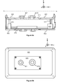
- FIG. 6 a shows a schematic illustration of a section view of a body module according to an embodiment of the invention.
- FIG. 6 b shows a schematic illustration of a view seen downwards from line A-A of FIG. 6 a .
- the body module comprises a first plate, a second plate, and walls extending from the outer edges of the first plate to the outer edges of the second plate.
- the second plate comprises a first part 603 the outer edges of which are in contact with the walls and a second part 615 that is detachably fastened to an opening of the first part.
- the second part 615 comprises one or more fastening interfaces 607 and 607 b each of which being suitable for an optical module to be mounted to the second plate.
- the second plate is movably supported to the first plate with sliding elements 613 and with a toothed bar 614 .
- An element 615 can be provided for example with a servomotor arranged to move the second plate.
- the first plate comprises a first part 602 the outer edges of which are in contact with the walls and a second part 616 detachably fastened to an opening of the first part.
- the second part comprises one or more fastening interfaces suitable for one or more optical modules to be mounted to the first plate.
Landscapes
- Physics & Mathematics (AREA)
- Health & Medical Sciences (AREA)
- Life Sciences & Earth Sciences (AREA)
- Chemical & Material Sciences (AREA)
- Analytical Chemistry (AREA)
- Biochemistry (AREA)
- General Health & Medical Sciences (AREA)
- General Physics & Mathematics (AREA)
- Immunology (AREA)
- Pathology (AREA)
- Investigating, Analyzing Materials By Fluorescence Or Luminescence (AREA)
- Investigating Or Analysing Materials By Optical Means (AREA)
- Optical Measuring Cells (AREA)
Priority Applications (1)
| Application Number | Priority Date | Filing Date | Title |
|---|---|---|---|
| US13/146,305 US8759789B2 (en) | 2009-01-26 | 2010-01-18 | Body module for an optical measurement instrument |
Applications Claiming Priority (5)
| Application Number | Priority Date | Filing Date | Title |
|---|---|---|---|
| FI20095061 | 2009-01-26 | ||
| FI20095061A FI20095061A0 (fi) | 2009-01-26 | 2009-01-26 | Optisen mittauslaitteen runkomoduuli |
| US14954409P | 2009-02-03 | 2009-02-03 | |
| PCT/FI2010/050020 WO2010084243A1 (en) | 2009-01-26 | 2010-01-18 | A body module for an optical measurement instrument |
| US13/146,305 US8759789B2 (en) | 2009-01-26 | 2010-01-18 | Body module for an optical measurement instrument |
Publications (2)
| Publication Number | Publication Date |
|---|---|
| US20120001089A1 US20120001089A1 (en) | 2012-01-05 |
| US8759789B2 true US8759789B2 (en) | 2014-06-24 |
Family
ID=40329516
Family Applications (1)
| Application Number | Title | Priority Date | Filing Date |
|---|---|---|---|
| US13/146,305 Active 2030-09-08 US8759789B2 (en) | 2009-01-26 | 2010-01-18 | Body module for an optical measurement instrument |
Country Status (7)
| Country | Link |
|---|---|
| US (1) | US8759789B2 (ja) |
| EP (1) | EP2382477B1 (ja) |
| JP (1) | JP5479496B2 (ja) |
| CN (1) | CN102308219B (ja) |
| CA (1) | CA2748450C (ja) |
| FI (1) | FI20095061A0 (ja) |
| WO (1) | WO2010084243A1 (ja) |
Families Citing this family (7)
| Publication number | Priority date | Publication date | Assignee | Title |
|---|---|---|---|---|
| FI20095059A0 (fi) * | 2009-01-26 | 2009-01-26 | Wallac Oy | Laitteisto ja menetelmä näytteiden optiseksi mittaamiseksi |
| FI20095063A0 (fi) * | 2009-01-26 | 2009-01-26 | Wallac Oy | Optinen mittauslaite |
| DE102010053475B4 (de) | 2010-12-04 | 2022-03-24 | Carl Zeiss Microscopy Gmbh | Vorrichtung zum lichtdichten Abschluss eines Probenraums und Mikroskop |
| WO2014145619A1 (en) * | 2013-03-15 | 2014-09-18 | Hycor Biomedical, Inc. | Device and associated methods for performing luminescence and fluorescence measurements of a sample |
| KR101811786B1 (ko) * | 2015-05-14 | 2017-12-22 | 바디텍메드(주) | 일체화된 반응 및 검출 수단을 구비한 시험 장치에 사용되는 스테이션 |
| CN106680250B (zh) * | 2015-11-10 | 2023-06-30 | 北京万泰生物药业股份有限公司 | 用于聚合酶链式反应的检测机构及聚合酶链式反应装置 |
| CN110763641B (zh) * | 2019-11-29 | 2024-04-09 | 京东方科技集团股份有限公司 | 检测装置和检测方法 |
Citations (17)
| Publication number | Priority date | Publication date | Assignee | Title |
|---|---|---|---|---|
| GB722967A (en) | 1952-10-28 | 1955-02-02 | Nat Res Dev | Improvements in or relating to cells for spectroscopy |
| US3628386A (en) * | 1970-03-05 | 1971-12-21 | Sorvall Inc Ivan | Micrometer stage advance device for scientific instruments or the like |
| US4311358A (en) * | 1978-11-01 | 1982-01-19 | De Forenede Bryggerier A/S | Illumination device for fluorescence microscopes |
| JPS638537A (ja) | 1986-06-27 | 1988-01-14 | Tosoh Corp | マイクロプレ−ト用吸光度測定装置 |
| EP0523521A2 (de) | 1991-07-18 | 1993-01-20 | Laboratorium Prof. Dr. Rudolf Berthold GmbH & Co. | Strahlungsmessgerät, insbesondere zur Lumineszenzmessung |
| EP0760478A2 (en) | 1995-08-25 | 1997-03-05 | Iatron Laboratories, Inc. | Light obstruction device for microplates |
| JPH10300660A (ja) | 1997-04-24 | 1998-11-13 | Hitachi Ltd | 発光観察装置 |
| JPH11316186A (ja) | 1998-04-30 | 1999-11-16 | Otsuka Denshi Kk | 固体サンプル測定用分光光度計 |
| WO2000004364A2 (en) | 1998-07-15 | 2000-01-27 | Ljl Biosystems, Inc. | Evanescent field illumination devices and methods |
| EP0987540A2 (en) | 1998-09-17 | 2000-03-22 | Wallac Oy | Sample imaging device |
| EP1400801A1 (en) | 2002-09-20 | 2004-03-24 | Wallac Oy | Instrumentation for optical measurement of the photoluminescence and chemiluminescenece of samples |
| CN1549921A (zh) | 2001-06-29 | 2004-11-24 | ÷ | 发光测试检测用的检测板、读数系统和方法 |
| WO2005111587A1 (ja) | 2004-05-18 | 2005-11-24 | Kabushiki Kaisya Advance | 生体試料検出装置 |
| US20060051251A1 (en) * | 2004-09-03 | 2006-03-09 | Symyx Technologies, Inc. | Substrate for sample analyses |
| WO2006027406A1 (en) | 2004-09-10 | 2006-03-16 | Wallac Oy | Instrumentation and method adapted for optical measurement of an amplified luminescent proximity homogeneous assay |
| JP2007010500A (ja) | 2005-06-30 | 2007-01-18 | Canon Inc | サンプル検出装置とそれを含む検体分析装置 |
| US20080252966A1 (en) * | 2007-04-12 | 2008-10-16 | Olympus Corporation | Fluorescence microscope apparatus |
Family Cites Families (1)
| Publication number | Priority date | Publication date | Assignee | Title |
|---|---|---|---|---|
| FI116946B (fi) * | 2004-07-09 | 2006-04-13 | Chip Man Technologies Oy | Laitteisto solujen kuvaamiseksi |
-
2009
- 2009-01-26 FI FI20095061A patent/FI20095061A0/fi not_active Application Discontinuation
-
2010
- 2010-01-18 US US13/146,305 patent/US8759789B2/en active Active
- 2010-01-18 CN CN201080005135.7A patent/CN102308219B/zh active Active
- 2010-01-18 CA CA2748450A patent/CA2748450C/en active Active
- 2010-01-18 JP JP2011546892A patent/JP5479496B2/ja active Active
- 2010-01-18 EP EP10702326A patent/EP2382477B1/en active Active
- 2010-01-18 WO PCT/FI2010/050020 patent/WO2010084243A1/en active Application Filing
Patent Citations (22)
| Publication number | Priority date | Publication date | Assignee | Title |
|---|---|---|---|---|
| GB722967A (en) | 1952-10-28 | 1955-02-02 | Nat Res Dev | Improvements in or relating to cells for spectroscopy |
| US3628386A (en) * | 1970-03-05 | 1971-12-21 | Sorvall Inc Ivan | Micrometer stage advance device for scientific instruments or the like |
| US4311358A (en) * | 1978-11-01 | 1982-01-19 | De Forenede Bryggerier A/S | Illumination device for fluorescence microscopes |
| JPS638537A (ja) | 1986-06-27 | 1988-01-14 | Tosoh Corp | マイクロプレ−ト用吸光度測定装置 |
| EP0523521A2 (de) | 1991-07-18 | 1993-01-20 | Laboratorium Prof. Dr. Rudolf Berthold GmbH & Co. | Strahlungsmessgerät, insbesondere zur Lumineszenzmessung |
| US5290513A (en) | 1991-07-18 | 1994-03-01 | Laboratorium Prof. Dr. Rudolf Berthold Gmbh & Co. Kg | Radiation measuring device, particularly for luminescence measurements |
| EP0760478A2 (en) | 1995-08-25 | 1997-03-05 | Iatron Laboratories, Inc. | Light obstruction device for microplates |
| JPH10300660A (ja) | 1997-04-24 | 1998-11-13 | Hitachi Ltd | 発光観察装置 |
| JPH11316186A (ja) | 1998-04-30 | 1999-11-16 | Otsuka Denshi Kk | 固体サンプル測定用分光光度計 |
| WO2000004364A2 (en) | 1998-07-15 | 2000-01-27 | Ljl Biosystems, Inc. | Evanescent field illumination devices and methods |
| EP0987540A2 (en) | 1998-09-17 | 2000-03-22 | Wallac Oy | Sample imaging device |
| CN1549921A (zh) | 2001-06-29 | 2004-11-24 | ÷ | 发光测试检测用的检测板、读数系统和方法 |
| US6977722B2 (en) | 2001-06-29 | 2005-12-20 | Meso Scale Technologies, Llc. | Assay plates, reader systems and methods for luminescence test measurements |
| US7842246B2 (en) | 2001-06-29 | 2010-11-30 | Meso Scale Technologies, Llc | Assay plates, reader systems and methods for luminescence test measurements |
| EP1400801A1 (en) | 2002-09-20 | 2004-03-24 | Wallac Oy | Instrumentation for optical measurement of the photoluminescence and chemiluminescenece of samples |
| US20040057870A1 (en) * | 2002-09-20 | 2004-03-25 | Christer Isaksson | Instrumentation for optical measurement of samples |
| WO2005111587A1 (ja) | 2004-05-18 | 2005-11-24 | Kabushiki Kaisya Advance | 生体試料検出装置 |
| US20060051251A1 (en) * | 2004-09-03 | 2006-03-09 | Symyx Technologies, Inc. | Substrate for sample analyses |
| WO2006027406A1 (en) | 2004-09-10 | 2006-03-16 | Wallac Oy | Instrumentation and method adapted for optical measurement of an amplified luminescent proximity homogeneous assay |
| JP2008512666A (ja) | 2004-09-10 | 2008-04-24 | ワラック オサケ ユキチュア | 増幅発光近接均質解析(AmplifiedLuminescentProximityHomogeneousAssay)の光学的測定に適合する器具類および方法 |
| JP2007010500A (ja) | 2005-06-30 | 2007-01-18 | Canon Inc | サンプル検出装置とそれを含む検体分析装置 |
| US20080252966A1 (en) * | 2007-04-12 | 2008-10-16 | Olympus Corporation | Fluorescence microscope apparatus |
Non-Patent Citations (3)
| Title |
|---|
| Finnish Search Report, dated Aug. 21, 2009, from corresponding Finnish application. |
| International Search Report, dated Apr. 26, 2010, from corresponding PCT application. |
| Translation of Chinese Office Action, dated Mar. 28, 2013, from corresponding CN application. |
Also Published As
| Publication number | Publication date |
|---|---|
| JP2012515910A (ja) | 2012-07-12 |
| US20120001089A1 (en) | 2012-01-05 |
| FI20095061A0 (fi) | 2009-01-26 |
| CA2748450C (en) | 2017-06-27 |
| WO2010084243A1 (en) | 2010-07-29 |
| CN102308219B (zh) | 2013-10-30 |
| CN102308219A (zh) | 2012-01-04 |
| EP2382477B1 (en) | 2012-11-28 |
| JP5479496B2 (ja) | 2014-04-23 |
| EP2382477A1 (en) | 2011-11-02 |
| CA2748450A1 (en) | 2010-07-29 |
Similar Documents
| Publication | Publication Date | Title |
|---|---|---|
| US8759789B2 (en) | Body module for an optical measurement instrument | |
| US6891618B2 (en) | Optical instrument and process for measurement of samples | |
| US8542349B2 (en) | Arrangement and a method for controlling a measurement head of an optical measurement instrument | |
| US7199879B2 (en) | Versatile instrumentation for optical measurement of samples | |
| US7843568B2 (en) | Enhanced instrumentation and method for optical measurement of samples | |
| US20040057870A1 (en) | Instrumentation for optical measurement of samples | |
| US20070177149A1 (en) | Instrumentation and method for optical measurement of samples | |
| KR20130123411A (ko) | 양자수율 측정장치 | |
| US8814427B2 (en) | Instrumentation and method for optical measurement of samples | |
| US8744269B2 (en) | Optical measurement instrument with data transmission | |
| JP6820122B2 (ja) | 選択可能な励起光経路を用いる光学ベースの測定のための方法およびシステム | |
| EP2486465B1 (en) | An optical measurement instrument |
Legal Events
| Date | Code | Title | Description |
|---|---|---|---|
| AS | Assignment |
Owner name: WALLAC OY, FINLAND Free format text: ASSIGNMENT OF ASSIGNORS INTEREST;ASSIGNOR:LAITINEN, JYRKI;REEL/FRAME:026930/0763 Effective date: 20110905 |
|
| FEPP | Fee payment procedure |
Free format text: PAYOR NUMBER ASSIGNED (ORIGINAL EVENT CODE: ASPN); ENTITY STATUS OF PATENT OWNER: LARGE ENTITY |
|
| STCF | Information on status: patent grant |
Free format text: PATENTED CASE |
|
| MAFP | Maintenance fee payment |
Free format text: PAYMENT OF MAINTENANCE FEE, 4TH YEAR, LARGE ENTITY (ORIGINAL EVENT CODE: M1551) Year of fee payment: 4 |
|
| MAFP | Maintenance fee payment |
Free format text: PAYMENT OF MAINTENANCE FEE, 8TH YEAR, LARGE ENTITY (ORIGINAL EVENT CODE: M1552); ENTITY STATUS OF PATENT OWNER: LARGE ENTITY Year of fee payment: 8 |