US8755194B2 - Waterproof element and electronic device having the waterproof element - Google Patents
Waterproof element and electronic device having the waterproof element Download PDFInfo
- Publication number
- US8755194B2 US8755194B2 US13/158,017 US201113158017A US8755194B2 US 8755194 B2 US8755194 B2 US 8755194B2 US 201113158017 A US201113158017 A US 201113158017A US 8755194 B2 US8755194 B2 US 8755194B2
- Authority
- US
- United States
- Prior art keywords
- main body
- circuit board
- face
- accommodating portion
- top face
- Prior art date
- Legal status (The legal status is an assumption and is not a legal conclusion. Google has not performed a legal analysis and makes no representation as to the accuracy of the status listed.)
- Active, expires
Links
Images


Classifications
-
- H—ELECTRICITY
- H05—ELECTRIC TECHNIQUES NOT OTHERWISE PROVIDED FOR
- H05K—PRINTED CIRCUITS; CASINGS OR CONSTRUCTIONAL DETAILS OF ELECTRIC APPARATUS; MANUFACTURE OF ASSEMBLAGES OF ELECTRICAL COMPONENTS
- H05K5/00—Casings, cabinets or drawers for electric apparatus
- H05K5/06—Hermetically-sealed casings
- H05K5/069—Other details of the casing, e.g. wall structure, passage for a connector, a cable, a shaft
-
- Y—GENERAL TAGGING OF NEW TECHNOLOGICAL DEVELOPMENTS; GENERAL TAGGING OF CROSS-SECTIONAL TECHNOLOGIES SPANNING OVER SEVERAL SECTIONS OF THE IPC; TECHNICAL SUBJECTS COVERED BY FORMER USPC CROSS-REFERENCE ART COLLECTIONS [XRACs] AND DIGESTS
- Y10—TECHNICAL SUBJECTS COVERED BY FORMER USPC
- Y10T—TECHNICAL SUBJECTS COVERED BY FORMER US CLASSIFICATION
- Y10T428/00—Stock material or miscellaneous articles
- Y10T428/24—Structurally defined web or sheet [e.g., overall dimension, etc.]
- Y10T428/24008—Structurally defined web or sheet [e.g., overall dimension, etc.] including fastener for attaching to external surface
-
- Y—GENERAL TAGGING OF NEW TECHNOLOGICAL DEVELOPMENTS; GENERAL TAGGING OF CROSS-SECTIONAL TECHNOLOGIES SPANNING OVER SEVERAL SECTIONS OF THE IPC; TECHNICAL SUBJECTS COVERED BY FORMER USPC CROSS-REFERENCE ART COLLECTIONS [XRACs] AND DIGESTS
- Y10—TECHNICAL SUBJECTS COVERED BY FORMER USPC
- Y10T—TECHNICAL SUBJECTS COVERED BY FORMER US CLASSIFICATION
- Y10T428/00—Stock material or miscellaneous articles
- Y10T428/24—Structurally defined web or sheet [e.g., overall dimension, etc.]
- Y10T428/24479—Structurally defined web or sheet [e.g., overall dimension, etc.] including variation in thickness
Definitions
- This invention relates to an electronic device, and more particularly to an electronic device having a waterproof element and the waterproof element thereof.
- I/O connecting ports of a conventional electronic device are formed as openings in a casing thereof to expose I/O connecting devices provided in the casing.
- the casing is provided with a waterproof dustproof cover for covering the connecting ports, or the I/O connecting device and a portion of the casing are made by an insert molding process.
- the waterproof dustproof cover can achieve its intended purpose, the casing of the conventional electronic device must have a sufficient space for accommodating the cover. In view of a small electronic device, it poses difficulty. In the case of insert molding the I/O connecting device, the cost is high.
- an object of the present invention is to provide a waterproof element that has a simple structure, that has a low cost, and that does not occupy a substantial space and an electronic device having the waterproof element.
- an electronic device comprises a housing unit, a waterproof element, and an electronic component module.
- the housing unit includes an accommodating portion, and first and second openings communicating with the accommodating portion.
- the waterproof element is made of a resilient material, and includes a main body that is disposed on the accommodating portion and that has a top face, and a side face extending upwardly from the top face.
- the electronic component module includes a circuit board and an electronic component.
- the circuit board has a board bottom face disposed on and abutting against the top face of the main body and covering the second opening, and a board edge abutting against the side face of the main body.
- the electronic component is attached to the circuit board, extends through the main body of the waterproof element, is disposed inside the accommodating portion, and faces the first opening.
- a waterproof element is adapted to be disposed between a housing unit and a circuit board.
- the circuit board has a board bottom face and a board edge.
- the waterproof element comprises a main body made of an elastic material and adapted to be disposed between the housing unit and the circuit board.
- the main body has a top face for abutment with the board bottom face of the circuit board, and a side face extending upwardly from the top face of the main body for abutment with the board edge of the circuit board.
- the efficiency of the present invention resides in the fact that through the structural design of the waterproof element, the circuit board is provided with upward, downward, and sideward abutments so that a good waterproof effect may be provided. Further, the whole structure of the waterproof element is simple, so that it has a low manufacturing cost, and it does not occupy a substantial space in the electronic device.
- FIG. 1 is a perspective view of an electronic device according to the preferred embodiment of the present invention.
- FIG. 2 is an exploded perspective view of the preferred embodiment, but with an upper casing member removed;
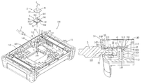
- FIG. 3 is an exploded perspective view of the preferred embodiment taken from another angle
- FIG. 4 is a schematic top view of the preferred embodiment in an assembled state
- FIG. 5 is a sectional view of the preferred embodiment taken along line A-A of FIG. 4 ;
- FIG. 6 is a view similar to FIG. 3 , but illustrating an alternative form of the waterproof element of the present invention.
- FIG. 7 is an assembled sectional view of FIG. 6 .
- an electronic device 100 comprises a housing unit 1 , an electronic component module 2 , a waterproof element 3 , and a fastening unit.
- the housing unit 1 is formed with an accommodating portion 11 , and first and second openings 12 , 13 both communicating with the accommodating portion 11 .
- the housing unit 1 includes a lower casing member 14 , and an upper casing member 15 connected to the lower casing member 14 .
- the lower casing member 14 includes a bottom wall 141 , and an outer upstanding wall 142 extending upwardly from a peripheral end of the bottom wall 141 and having an inner surface 146 .
- the bottom wall 141 and the outer upstanding wall 142 cooperatively define a receiving space 143 .
- the accommodating portion 11 is formed in the lower casing member 14 , and includes an inner upstanding wall 111 extending upwardly from the bottom wall 141 within the receiving space 143 .
- the inner upstanding wall 111 extends in a U-shaped configuration, and has two opposite ends connected to a portion of the inner surface 146 of the outer upstanding wall 142 .
- the inner upstanding wall 111 and the portion of the inner surface 146 of the outer upstanding wall 142 cooperatively define an accommodating space 112 located within the receiving space 143 .
- the first opening 12 is formed in the outer upstanding wall 142 at a position corresponding to and communicating with the accommodating space 112 .
- the inner upstanding wall 111 further has a top edge 113 defining the second opening 13 .
- the electronic component module 2 includes a circuit board 21 , and an electronic component 22 attached to the circuit board 21 .
- the circuit board 21 is disposed above the top edge 113 of the inner upstanding wall 111 so that the electronic component 22 is located inside the accommodating space 112 .
- the circuit board 21 as shown in FIG. 5 , has a board bottom face 211 and a board edge 212 .
- the electronic component 22 is formed with a plug hole 221 that faces the first opening 12 .
- the electronic component 22 in this embodiment, may be an I/O connecting device, such as a USB, PCMIA, or VGA connecting device, and may be fixed to the circuit board 21 by using solder paste or an SMT (surface mount technology) method. Alternatively, the electronic component 22 may be in other forms.
- the waterproof element 3 is disposed between the top edge 113 and the circuit board 21 to prevent a liquid body entering the accommodating space 112 via the first opening 12 to flow into the receiving space 145 via the second opening 13 .
- the waterproof element 3 is made of a resilient material, such as silicone or rubber, and includes a main body 31 having a top face 311 , and a side face 312 extending upwardly from the top face 311 .
- the main body 31 includes first and second wall portions 32 , 33 connected to each other and forming an L-shaped configuration.
- the first wall portion 32 extends in a U-shaped configuration, and has the top face 311 , two opposite ends 321 connected to the second wall portion 33 , and a bottom face 322 opposite to the top face 311 .
- the first wall portion 32 is disposed on the top edge 113 of the inner upstanding wall 111 .
- the electronic component 22 extends through the first wall portion 32 , and is accommodated inside the accommodating space 112 .
- the second wall portion 33 has the side
- the fastening unit includes a plurality of fastening elements 4 that are configured as screws in this embodiment.
- the bottom face 322 of the first wall portion 32 abuts against the top edge 113
- another face of the second wall portion 33 that is opposite to the side face 312 abuts against the portion of the inner surface 146 of the outer upstanding wall 142 .
- the board bottom face 211 of the circuit board 21 abuts against the top face 311 of the first wall portion 31 , and covers the second opening 13 .
- the board edge 212 of the circuit board 21 abuts against the side face 312 .
- a plug connecting device 5 is inserted into the plug hole 221 in the electronic component 22 via the first opening 12 .
- the fastening elements 4 extend through the circuit board 21 and the first wall portion 32 of the main body 31 of the waterproof element 3 to respectively engage screw holes 144 (which may be preformed in the bottom wall 141 of the lower casing member 14 ) in the bottom wall 141 to thereby fix the electronic component module 2 to the housing unit 1 .
- the waterproof element 3 is pressed tightly between the circuit board 21 and the top edge 113 , thereby preventing a liquid body entering the accommodating space 112 via the first opening 12 to flow through a gap between the circuit board 21 and the top edge 113 into the receiving space 143 and affect the other electronic components provided inside the housing unit 1 .
- the board edge 212 of the circuit board 21 can be pressed tightly against the side face 312 of the second wall portion 33 when the fastening elements 4 are engaged to the bottom wall 141 .
- the waterproof element 3 is providing the circuit board 21 with upward, downward, and sideward abutments, so that waterproof effects on these directions of the circuit board 21 are also provided.
- the first wall portion 32 of the waterproof element 3 has a protrusion 313 projecting from and extending along the top face 311 thereof for abutment of the board bottom face 211 of the circuit board 21 against the protrusion 313 .
- the circuit board 21 forms a compression force on the protrusion 313 to ensure that the circuit board 21 can completely abut against the top face 311 of the waterproof element 3 , thereby preventing easy formation of a gap between contact surfaces of the two.
- two opposite ends of the protrusion 313 extend to a junction between the first and second wall portions 32 , 33 .
- the first wall portion 32 has an engaging groove 323 formed in and extending along the bottom face 322 thereof to engage the top edge 113 of the inner upstanding wall 111 .
- the engaging groove 323 formed in and extending along the bottom face 322 thereof to engage the top edge 113 of the inner upstanding wall 111 .
- the fastening elements 4 are configured as screws.
- elements that can interconnect two objects can be used as the fastening elements 4 , for example, hooks, rivets, etc.
- FIGS. 6 and 7 illustrate an alternative form of the waterproof element 3 ′ which is substantially similar to the waterproof element 3 .
- the waterproof element 3 ′ further includes a flange 34 projecting from the side face 312 of the second wall portion 33 above the top face 311 of the first wall portion 32 .
- the circuit board 21 is inserted between the flange 34 and the top face 311 .
- the board edge 212 of the circuit board 21 abuts against the side face 312
- the circuit board 21 is simultaneously suppressed by the flange 34 , thereby increasing stability of abutment of the circuit board 21 against the main body 31 of the waterproof element 3 ′.
Landscapes
- Engineering & Computer Science (AREA)
- Microelectronics & Electronic Packaging (AREA)
- Casings For Electric Apparatus (AREA)
Applications Claiming Priority (2)
| Application Number | Priority Date | Filing Date | Title |
|---|---|---|---|
| TW099138815 | 2010-11-11 | ||
| TW99138815A TWI429146B (zh) | 2010-11-11 | 2010-11-11 | 電子裝置及其防水元件 |
Publications (2)
| Publication Number | Publication Date |
|---|---|
| US20120120620A1 US20120120620A1 (en) | 2012-05-17 |
| US8755194B2 true US8755194B2 (en) | 2014-06-17 |
Family
ID=46047592
Family Applications (1)
| Application Number | Title | Priority Date | Filing Date |
|---|---|---|---|
| US13/158,017 Active 2031-06-23 US8755194B2 (en) | 2010-11-11 | 2011-06-10 | Waterproof element and electronic device having the waterproof element |
Country Status (2)
| Country | Link |
|---|---|
| US (1) | US8755194B2 (zh) |
| TW (1) | TWI429146B (zh) |
Families Citing this family (6)
| Publication number | Priority date | Publication date | Assignee | Title |
|---|---|---|---|---|
| TWM408916U (en) * | 2011-01-24 | 2011-08-01 | Wistron Corp | Assembly of the housing, heat-dissipation module, and waterproof module, and waterproof module of electronic device |
| CN103838342A (zh) * | 2012-11-23 | 2014-06-04 | 鸿富锦精密工业(深圳)有限公司 | 电源 |
| CN104936390B (zh) * | 2014-03-18 | 2017-12-29 | 神讯电脑(昆山)有限公司 | 具有喇叭网膜的防水门 |
| CN105992481B (zh) * | 2015-02-10 | 2018-12-04 | 纬创资通股份有限公司 | 固定机构及具有电路板快拆功能的电子装置 |
| CN107948884B (zh) * | 2017-11-22 | 2021-02-26 | 瑞声科技(新加坡)有限公司 | 扬声器模组 |
| CN110568910B (zh) * | 2019-08-28 | 2024-03-22 | 英业达科技有限公司 | 车用主机及车用计算机系统 |
Citations (23)
| Publication number | Priority date | Publication date | Assignee | Title |
|---|---|---|---|---|
| US5045971A (en) * | 1989-04-18 | 1991-09-03 | Mitsubishi Denki Kabushiki Kaisha | Electronic device housing with temperature management functions |
| US5782658A (en) * | 1995-04-26 | 1998-07-21 | Sumitomo Wiring Systems, Ltd. | Tubular supporting structure |
| US5845803A (en) * | 1995-01-27 | 1998-12-08 | Mitsubishi Denki Kabushiki Kaisha | Waterproof casing structure for electronic equipment |
| US6133531A (en) * | 1998-11-03 | 2000-10-17 | Pass & Seymour, Inc. | Weatherproof outlet cover |
| US6146198A (en) * | 1998-09-08 | 2000-11-14 | Yazaki Corporation | Waterproof connector |
| US20010018490A1 (en) * | 2000-02-15 | 2001-08-30 | Naruhiko Mashita | Resin composition, gasket material and gasket integrated with metal |
| US20010021103A1 (en) * | 2000-01-12 | 2001-09-13 | Omron Corporation | Control unit and method of manufacturing the same |
| US6311865B1 (en) * | 1998-12-28 | 2001-11-06 | LAURENT HERVé J. | Arrangement for resealing carbonated beverage containers |
| US6350949B1 (en) * | 2000-06-23 | 2002-02-26 | Tyco Electronics Corp | Sealed power distribution module |
| US6559380B2 (en) * | 2001-02-06 | 2003-05-06 | Thomas Soboleski | Weatherproof cover |
| US6977354B1 (en) * | 2004-11-03 | 2005-12-20 | Eaton Corporation | Arc hood and power distribution system including the same |
| US7061775B2 (en) * | 2002-01-16 | 2006-06-13 | Rockwell Automation Technologies, Inc. | Power converter having improved EMI shielding |
| US7372705B1 (en) * | 2006-02-01 | 2008-05-13 | Cisco Technology, Inc. | Portable data routing device and method of use |
| US20080188107A1 (en) * | 2007-02-01 | 2008-08-07 | Motorola, Inc. | Submersible electrical connector assembly and method of forming same |
| US7464814B2 (en) * | 2005-01-28 | 2008-12-16 | Carnevali Jeffrey D | Dry box with movable protective cover |
| US20090109635A1 (en) * | 2007-10-26 | 2009-04-30 | Wistron Corporation | Waterproof structure and portable electrical apparatus using the same |
| US7648043B2 (en) * | 2006-06-03 | 2010-01-19 | Kuan-Wei Chen | Waterproof cover with a water blocking flange for an audio system |
| US7679923B2 (en) * | 2005-10-18 | 2010-03-16 | JText Corporation | Method for applying coating agent and electronic control unit |
| CN201430736Y (zh) | 2009-06-30 | 2010-03-24 | 纬创资通股份有限公司 | 具有主机板防水结构的电子装置 |
| US20100206704A1 (en) * | 2009-02-19 | 2010-08-19 | Denso Corporation | Electronic key |
| US20100267264A1 (en) * | 2009-04-17 | 2010-10-21 | Yazaki Corporation | Waterproof connector |
| US7936566B2 (en) * | 2005-11-15 | 2011-05-03 | Hitachi, Ltd. | Electronic control unit and waterproof case |
| US20110235290A1 (en) * | 2008-12-08 | 2011-09-29 | Robert Bosch Gmbh | Electrical circuit assembly, control device and method for producing an electrical circuit assembly |
-
2010
- 2010-11-11 TW TW99138815A patent/TWI429146B/zh active
-
2011
- 2011-06-10 US US13/158,017 patent/US8755194B2/en active Active
Patent Citations (23)
| Publication number | Priority date | Publication date | Assignee | Title |
|---|---|---|---|---|
| US5045971A (en) * | 1989-04-18 | 1991-09-03 | Mitsubishi Denki Kabushiki Kaisha | Electronic device housing with temperature management functions |
| US5845803A (en) * | 1995-01-27 | 1998-12-08 | Mitsubishi Denki Kabushiki Kaisha | Waterproof casing structure for electronic equipment |
| US5782658A (en) * | 1995-04-26 | 1998-07-21 | Sumitomo Wiring Systems, Ltd. | Tubular supporting structure |
| US6146198A (en) * | 1998-09-08 | 2000-11-14 | Yazaki Corporation | Waterproof connector |
| US6133531A (en) * | 1998-11-03 | 2000-10-17 | Pass & Seymour, Inc. | Weatherproof outlet cover |
| US6311865B1 (en) * | 1998-12-28 | 2001-11-06 | LAURENT HERVé J. | Arrangement for resealing carbonated beverage containers |
| US20010021103A1 (en) * | 2000-01-12 | 2001-09-13 | Omron Corporation | Control unit and method of manufacturing the same |
| US20010018490A1 (en) * | 2000-02-15 | 2001-08-30 | Naruhiko Mashita | Resin composition, gasket material and gasket integrated with metal |
| US6350949B1 (en) * | 2000-06-23 | 2002-02-26 | Tyco Electronics Corp | Sealed power distribution module |
| US6559380B2 (en) * | 2001-02-06 | 2003-05-06 | Thomas Soboleski | Weatherproof cover |
| US7061775B2 (en) * | 2002-01-16 | 2006-06-13 | Rockwell Automation Technologies, Inc. | Power converter having improved EMI shielding |
| US6977354B1 (en) * | 2004-11-03 | 2005-12-20 | Eaton Corporation | Arc hood and power distribution system including the same |
| US7464814B2 (en) * | 2005-01-28 | 2008-12-16 | Carnevali Jeffrey D | Dry box with movable protective cover |
| US7679923B2 (en) * | 2005-10-18 | 2010-03-16 | JText Corporation | Method for applying coating agent and electronic control unit |
| US7936566B2 (en) * | 2005-11-15 | 2011-05-03 | Hitachi, Ltd. | Electronic control unit and waterproof case |
| US7372705B1 (en) * | 2006-02-01 | 2008-05-13 | Cisco Technology, Inc. | Portable data routing device and method of use |
| US7648043B2 (en) * | 2006-06-03 | 2010-01-19 | Kuan-Wei Chen | Waterproof cover with a water blocking flange for an audio system |
| US20080188107A1 (en) * | 2007-02-01 | 2008-08-07 | Motorola, Inc. | Submersible electrical connector assembly and method of forming same |
| US20090109635A1 (en) * | 2007-10-26 | 2009-04-30 | Wistron Corporation | Waterproof structure and portable electrical apparatus using the same |
| US20110235290A1 (en) * | 2008-12-08 | 2011-09-29 | Robert Bosch Gmbh | Electrical circuit assembly, control device and method for producing an electrical circuit assembly |
| US20100206704A1 (en) * | 2009-02-19 | 2010-08-19 | Denso Corporation | Electronic key |
| US20100267264A1 (en) * | 2009-04-17 | 2010-10-21 | Yazaki Corporation | Waterproof connector |
| CN201430736Y (zh) | 2009-06-30 | 2010-03-24 | 纬创资通股份有限公司 | 具有主机板防水结构的电子装置 |
Non-Patent Citations (2)
| Title |
|---|
| Office Action and English translation thereof for corresponding Chinese Application No. 201010050889.2 dated Nov. 20, 2013. |
| Office Action and English translation thereof for corresponding Taiwanese Application No. 099138815 dated Jun. 21, 2013. |
Also Published As
| Publication number | Publication date |
|---|---|
| TW201220616A (en) | 2012-05-16 |
| TWI429146B (zh) | 2014-03-01 |
| US20120120620A1 (en) | 2012-05-17 |
Similar Documents
| Publication | Publication Date | Title |
|---|---|---|
| US8755194B2 (en) | Waterproof element and electronic device having the waterproof element | |
| JP4675650B2 (ja) | 遊技機の回路基板収納箱 | |
| US7985090B2 (en) | Socket with an improved cover lid | |
| TWI590067B (zh) | 通用序列匯流排插槽及其相關電子裝置 | |
| JP5391308B2 (ja) | 防水コネクタ | |
| JP5759914B2 (ja) | 電子制御装置 | |
| US20080304244A1 (en) | Electrical connector having improved housing | |
| JP5766029B2 (ja) | コネクタ | |
| US7963800B1 (en) | Electrical connector having improved housing and shell | |
| US9653828B1 (en) | Electrical connector | |
| US5153380A (en) | Wave separator housing structure | |
| TWI751369B (zh) | 電連接器及其夾持件 | |
| TWI711227B (zh) | 保護蓋及電連接器組件 | |
| US20100105218A1 (en) | Electrical connector for receiving cpu | |
| US20080032527A1 (en) | Ieee 1394 electrical connector | |
| US9653857B1 (en) | Electronic device and loose-proof module | |
| JPH0670292U (ja) | 防水ケース構造 | |
| TWI689141B (zh) | 卡緣連接器 | |
| TW201524023A (zh) | 防水防塵插座 | |
| CN109196744B (zh) | 基板单元 | |
| TWM461212U (zh) | 具防水功能之電連接器以及電子裝置 | |
| EP3629435A1 (en) | Panel assembly and multigang panel | |
| US20140334122A1 (en) | Riser card assembly | |
| JP4469696B2 (ja) | 部品の接合構造及び電子機器 | |
| US9627786B2 (en) | Electrical connector with improved contacts |
Legal Events
| Date | Code | Title | Description |
|---|---|---|---|
| AS | Assignment |
Owner name: WISTRON CORPORATION, TAIWAN Free format text: ASSIGNMENT OF ASSIGNORS INTEREST;ASSIGNORS:SU, CHIA-CHENG;CHEN, TSUNG-HSIEN;HSU, PO-YUAN;AND OTHERS;REEL/FRAME:026463/0964 Effective date: 20110516 |
|
| STCF | Information on status: patent grant |
Free format text: PATENTED CASE |
|
| FPAY | Fee payment |
Year of fee payment: 4 |
|
| MAFP | Maintenance fee payment |
Free format text: PAYMENT OF MAINTENANCE FEE, 8TH YEAR, LARGE ENTITY (ORIGINAL EVENT CODE: M1552); ENTITY STATUS OF PATENT OWNER: LARGE ENTITY Year of fee payment: 8 |