US8730331B2 - Display apparatus and calibration method therefor - Google Patents
Display apparatus and calibration method therefor Download PDFInfo
- Publication number
- US8730331B2 US8730331B2 US13/314,920 US201113314920A US8730331B2 US 8730331 B2 US8730331 B2 US 8730331B2 US 201113314920 A US201113314920 A US 201113314920A US 8730331 B2 US8730331 B2 US 8730331B2
- Authority
- US
- United States
- Prior art keywords
- calibration
- guide image
- areas
- area
- displaying
- Prior art date
- Legal status (The legal status is an assumption and is not a legal conclusion. Google has not performed a legal analysis and makes no representation as to the accuracy of the status listed.)
- Active, expires
Links
Images


Classifications
-
- H—ELECTRICITY
- H04—ELECTRIC COMMUNICATION TECHNIQUE
- H04N—PICTORIAL COMMUNICATION, e.g. TELEVISION
- H04N17/00—Diagnosis, testing or measuring for television systems or their details
- H04N17/02—Diagnosis, testing or measuring for television systems or their details for colour television signals
-
- G—PHYSICS
- G01—MEASURING; TESTING
- G01J—MEASUREMENT OF INTENSITY, VELOCITY, SPECTRAL CONTENT, POLARISATION, PHASE OR PULSE CHARACTERISTICS OF INFRARED, VISIBLE OR ULTRAVIOLET LIGHT; COLORIMETRY; RADIATION PYROMETRY
- G01J3/00—Spectrometry; Spectrophotometry; Monochromators; Measuring colours
- G01J3/46—Measurement of colour; Colour measuring devices, e.g. colorimeters
- G01J3/50—Measurement of colour; Colour measuring devices, e.g. colorimeters using electric radiation detectors
- G01J3/506—Measurement of colour; Colour measuring devices, e.g. colorimeters using electric radiation detectors measuring the colour produced by screens, monitors, displays or CRTs
-
- G—PHYSICS
- G09—EDUCATION; CRYPTOGRAPHY; DISPLAY; ADVERTISING; SEALS
- G09G—ARRANGEMENTS OR CIRCUITS FOR CONTROL OF INDICATING DEVICES USING STATIC MEANS TO PRESENT VARIABLE INFORMATION
- G09G3/00—Control arrangements or circuits, of interest only in connection with visual indicators other than cathode-ray tubes
- G09G3/20—Control arrangements or circuits, of interest only in connection with visual indicators other than cathode-ray tubes for presentation of an assembly of a number of characters, e.g. a page, by composing the assembly by combination of individual elements arranged in a matrix no fixed position being assigned to or needed to be assigned to the individual characters or partial characters
-
- G—PHYSICS
- G09—EDUCATION; CRYPTOGRAPHY; DISPLAY; ADVERTISING; SEALS
- G09G—ARRANGEMENTS OR CIRCUITS FOR CONTROL OF INDICATING DEVICES USING STATIC MEANS TO PRESENT VARIABLE INFORMATION
- G09G2320/00—Control of display operating conditions
- G09G2320/02—Improving the quality of display appearance
- G09G2320/0233—Improving the luminance or brightness uniformity across the screen
-
- G—PHYSICS
- G09—EDUCATION; CRYPTOGRAPHY; DISPLAY; ADVERTISING; SEALS
- G09G—ARRANGEMENTS OR CIRCUITS FOR CONTROL OF INDICATING DEVICES USING STATIC MEANS TO PRESENT VARIABLE INFORMATION
- G09G2320/00—Control of display operating conditions
- G09G2320/02—Improving the quality of display appearance
- G09G2320/0242—Compensation of deficiencies in the appearance of colours
-
- G—PHYSICS
- G09—EDUCATION; CRYPTOGRAPHY; DISPLAY; ADVERTISING; SEALS
- G09G—ARRANGEMENTS OR CIRCUITS FOR CONTROL OF INDICATING DEVICES USING STATIC MEANS TO PRESENT VARIABLE INFORMATION
- G09G2320/00—Control of display operating conditions
- G09G2320/02—Improving the quality of display appearance
- G09G2320/029—Improving the quality of display appearance by monitoring one or more pixels in the display panel, e.g. by monitoring a fixed reference pixel
- G09G2320/0295—Improving the quality of display appearance by monitoring one or more pixels in the display panel, e.g. by monitoring a fixed reference pixel by monitoring each display pixel
-
- G—PHYSICS
- G09—EDUCATION; CRYPTOGRAPHY; DISPLAY; ADVERTISING; SEALS
- G09G—ARRANGEMENTS OR CIRCUITS FOR CONTROL OF INDICATING DEVICES USING STATIC MEANS TO PRESENT VARIABLE INFORMATION
- G09G2320/00—Control of display operating conditions
- G09G2320/06—Adjustment of display parameters
- G09G2320/0693—Calibration of display systems
-
- G—PHYSICS
- G09—EDUCATION; CRYPTOGRAPHY; DISPLAY; ADVERTISING; SEALS
- G09G—ARRANGEMENTS OR CIRCUITS FOR CONTROL OF INDICATING DEVICES USING STATIC MEANS TO PRESENT VARIABLE INFORMATION
- G09G2360/00—Aspects of the architecture of display systems
- G09G2360/14—Detecting light within display terminals, e.g. using a single or a plurality of photosensors
- G09G2360/145—Detecting light within display terminals, e.g. using a single or a plurality of photosensors the light originating from the display screen
-
- H—ELECTRICITY
- H04—ELECTRIC COMMUNICATION TECHNIQUE
- H04N—PICTORIAL COMMUNICATION, e.g. TELEVISION
- H04N5/00—Details of television systems
- H04N5/44—Receiver circuitry for the reception of television signals according to analogue transmission standards
- H04N5/57—Control of contrast or brightness
Definitions
- Methods and apparatuses consistent with the exemplary embodiments relate to a display apparatus and calibration method therefor, and more particularly, to a display apparatus for performing calibration using a calibrator, and a calibration method therefor.
- the uniformity characteristics of a display apparatus are extremely important elements.
- the required uniformity is 95% or more. Due to the optical, electrical, and physical characteristics of the current display apparatuses (liquid crystal display (LCD), plasma display panel (PDP), organic light emitting diode (OLED), etc.), there is a significant cost associated with satisfying the required specifications, and thus a method to solve this problem through signal processing is needed.
- LCD liquid crystal display
- PDP plasma display panel
- OLED organic light emitting diode
- Signal processing can be used to measure the brightness through an external calibrator, and to perform non-uniformity correction using the measured information.
- the entire display size of the pertinent local area is displayed in order to measure relevant data, such as the color coordinates and brightness of the pertinent local area, for non-uniformity correction.
- relevant data such as the color coordinates and brightness of the pertinent local area
- a sensor of the calibrator if a sensor of the calibrator is not placed where the user intends to measure, the sensor is rendered unable to perform an exact non-uniformity correction.
- the sensor is rendered unable to perform an exact non-uniformity correction.
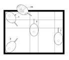
- FIGS. 1A to 1D are views which illustrate several problems of the conventional art.
- FIG. 1A is a view illustrating the nonconformity relationship of a calibrator and a measuring position when performing a non-uniformity correction on a local area of 5 ⁇ 5.
- a situation may occur where the calibrator is caught on a bezel of a display screen, making it impossible to measure the data.
- the user must rotate the calibrator 180° for an exact measurement.
- FIG. 1C another situation may occur which presents a problem that the greater the number of the local areas, as, for example, in a local area of 7 ⁇ 7, the greater the number of various angles to which the user must rotate the calibrator to perform an exact measurement.
- An aspect of the exemplary embodiments relates to a display apparatus for displaying a guide image which guides an arrangement position of a calibrator, and a calibration method therefor.
- a display apparatus includes a display unit which displays a calibration screen which is divided into a plurality of areas when a calibration mode is initiated, an image generating unit which generates a guide image for displaying an arrangement position of a calibrator, and a controlling unit which controls the display unit to display the guide image on an area of the plurality of areas where a calibration is to be performed.
- the controlling unit may control the display unit to display the guide image on one of the areas where calibration is to be performed, delete the guide image which was displayed when the calibration is performed in the respective area, and display the guide image on a next area.
- the controlling unit may control the display unit to display a plurality of guide images on all areas where the calibration is to be performed.
- the controlling unit may control the display unit to delete guide images from the plurality of guide images on areas where calibration has been performed.
- the guide image is of a same shape and size as the calibrator, and a guide image displayed on an edge area or a corner area of the plurality of areas may be rotated so that the calibration can be performed in the center of the respective area.
- the guide image may be a guide image which displays directivity so as to induce rotation of the calibrator in edge areas or corner areas of the plurality of areas.
- a calibration method includes displaying a calibration screen which is divided into a plurality of areas when a calibration mode is initiated, and displaying guide images on areas from the plurality of areas where calibration is to be performed.
- the displaying may include displaying a guide image on one of the areas where the calibration is to be performed, deleting the guide image which was displayed when the calibration is completed in the area where the guide image is displayed, and displaying a guide image on a next area from the plurality of areas where the calibration is to be performed.
- the displaying may include displaying a plurality of guide images on all areas where the calibration is to be performed.
- the displaying may further include deleting guide images on areas from the plurality of areas where the calibration has been completed.
- the guide image may be of a same shape and size as the calibrator, and a guide image displayed on an edge area or a corner area of the plurality of areas may be rotated so that the calibration is performed in the center of the respective area.
- the guide image may be a guide image which displays directivity so as to induce rotation of the calibration on the edge areas or the corner areas of the plurality of areas.
- a record medium for storing a program for performing a calibration method of a display apparatus includes displaying a calibration screen which is divided into a plurality of areas when a calibration mode is initiated, and displaying a guide image for displaying an arrangement position of a calibrator on an area from the plurality of areas where a calibration is to be performed.
- the displaying may include displaying the guide image on one of the areas where the calibration is to be performed, and deleting the guide image which was displayed when the calibration is completed on the area where the guide image is displayed, and displaying the guide image on a next area from the plurality of areas where the calibration is to be performed.
- the displaying may include displaying a plurality of guide images on all the areas where the calibration is to be performed.
- the displaying may further include deleting the guide images on the areas from the plurality of areas where the calibration has been completed.
- the guide image may be of the same shape and size as the calibrator, and a guide image which is displayed on an edge area or a corner area of the plurality of areas may be rotated so that calibration is performed in the center of the respective area.
- the guide image may be a guide image which displays directivity so as to induce rotation of the calibrator in the edge area or the corner area of the plurality of areas.
- a recording medium for storing a program performing a calibration method of a display apparatus may include displaying a calibration screen which is divided into a plurality of areas, and displaying guide images for displaying an arrangement position of a calibrator on areas from the plurality of areas where the calibration is to be performed.
- the guide image is of a same shape and size as the calibrator, and a guide image displayed on an edge area or a corner area of the plurality of areas may be rotated so that the calibration is performed in the center of the respective area.
- the guide image may also be a guide image which displays directivity so as to induce rotation of the calibrator in the edge areas or the corner areas of the plurality of areas.
- FIGS. 1A , 1 B, 1 C, and 1 D are views which illustrate several problems of the conventional art
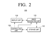
- FIG. 2 is a block diagram which illustrates a configuration of a display apparatus according to an exemplary embodiment of the present inventive concept
- FIGS. 3A and 3B are views which illustrate the structures of a front side and a back side of a display calibrator according to an exemplary embodiment of the present inventive concept
- FIG. 4 is a view which illustrates a guide image displaying method according to an exemplary embodiment of the present inventive concept
- FIGS. 5A , 5 B, and 5 C are views which illustrate a guide image shape according to various exemplary embodiments of the present inventive concept
- FIG. 6 is a view which illustrates a shape of a calibrator information according to an exemplary embodiment of the present inventive concept.
- FIG. 7 is a flow chart which illustrates a calibration method of a display apparatus according to an exemplary embodiment of the present inventive concept.
- FIG. 2 is a block diagram which illustrates a configuration of a display apparatus according to an exemplary embodiment of the present inventive concept.
- the display apparatus 100 may be configured to perform a non-uniformity correction operation using a calibrator.
- the display apparatus 100 may display a guide image of an arrangement position of the calibrator so that an exact calibration can be performed in consideration of the apparatus characteristics and the size of the calibrator and the display apparatus during a non-uniformity correction operation.
- the display apparatus 100 may be embodied in various shapes.
- the display apparatus 100 may be embodied as a professional monitor or a broadcasting reference television where display uniformity functions as a major element.
- the display apparatus 100 may be embodied as one of various display apparatuses which display image signals such as, for example, a digital television, a desktop computer, a notebook computer, a mobile telephone, a digital broadcasting terminal, or a navigation terminal.
- a display unit 110 may be embodied as at least one of a liquid crystal display, a thin film transistor-liquid crystal display, a plasma display panel, an organic light-emitting diode, a flexible display, and a three-dimensional display.
- the display unit 110 may display a calibration screen which is divided into a plurality of areas when a calibration mode for performing a non-uniformity correction is initiated. For example, it may be divided into a 5 ⁇ 5 pattern of areas or a 7 ⁇ 5 pattern of areas in consideration of the shape and size of the display unit 110 , and such ratio of area division may be saved in default or embodied so as to be selectable by the user.
- a calibration mode may be entered through a user command or predetermined event, such as, for example, a prescribed menu or a particular button.
- the calibration mode may be a mode for correcting a non-uniformity phenomenon where a color information moves or brightness changes even when the same color must be expressed due to color characteristics, electrical characteristics or optical characteristics as described above.
- An image generating unit 120 may generate a guide image for displaying an arrangement position of the calibrator.
- the image generating unit 120 may generate the guide image in graphical user interface (GUI) forms displayed on the calibration screen.
- GUI graphical user interface
- the image generating unit 120 may generate a guide image for guiding the arrangement position of the calibrator by using an actual image stored in a storage unit 140 .
- a user of the display apparatus 100 is able to perform an exact calibration operation because a guide image for guiding an arrangement position of the calibrator is displayed in consideration of an apparatus characteristics and size of the calibrator and display apparatus so that the calibrator can measure exact positions of each area on the display screen.
- FIGS. 3A and 3B are views which illustrate a structure of a front side and back side of the display calibrator according to an exemplary embodiment of the present inventive concept.
- a spectrophotometer or a chromameter may be used as a calibrator.
- a spectrophotometer can directly be used in a color mixing process because the spectrophotometer can obtain a color arrangement value automatically.
- the spectrophotometer uses a spectral strength distribution to calculate a color value, color values may be obtained under various light source conditions.
- the configuration of a chromameter is relatively simple and consists of inexpensive equipments such as a light source specimen rock and a photodetector. Detailed explanation of the above shall be omitted.
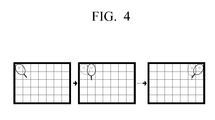
- FIG. 4 is a view which illustrates a guide image displaying method according to an exemplary embodiment of the present inventive concept.
- FIG. 4 illustrates a case where calibration is performed in a left-to-right direction starting from a top left corner area in consecutive order.
- a guide image corresponding to the top left corner area is displayed, and when calibration of the respective area is performed, the guide image displayed on the respective area disappears and a guide image corresponding to a next area is displayed.
- the exemplary embodiment illustrated in FIG. 4 is a mere example, and thus according to other exemplary embodiments, it may be possible to embody the guide images of the areas where calibration has been completed to disappear in consecutive order.
- a guide image of a calibrator may be of a same shape and size as the calibrator which is actually used.
- the guide images which are displayed on corner areas or edge areas of a plurality of areas divided for a calibration operation may be rotated so that calibration is performed in the center of the respective area.
- the guide image of a calibrator may be one of guide images a, b, c, d, each of which displays the directivity and a portion of the calibrator.
- the guide images a, b, c, d may be guide images which display the directivity so as to induce rotation of the calibrator in the corner areas or the edges area of the plurality of areas divided for calibration operation.
- the guide images of the calibrator may merely be guide images a′, b′, c′, d′ which display the directivity in each respective area.
- the guide images a′, b′, c′, d′ may be guide images which display the directivity so as to induce rotation of the calibrator in the edge areas or the corner areas of the plurality of areas divided for calibration operation.
- FIGS. 5A and 5B show the shapes of the guide images in each area, and it should be apparent to those of ordinary skill in the art that these drawing figures represent a state where the guide image is displayed at several points.
- FIG. 6 is a view which illustrates a state of calibrator information according to an exemplary embodiment of the present inventive concept.
- the display apparatus 100 may be storing a calibrator image corresponding to each model type, and if a predetermined calibrator model is selected according to predetermined event or a user command, it becomes possible to generate a guide image by using a stored image.
- FIG. 7 is a flow chart to illustrate a calibration method of a display apparatus according to an exemplary embodiment of the present inventive concept.
- a calibration screen divided into a plurality of areas is displayed at step S 710 .
- a guide image for displaying an arrangement position of the calibrator is displayed on an area of the plurality of areas where calibration is to be performed, at step S 720 .
- S 720 may include displaying the guide image on one area of the areas where calibration is to be performed, deleting the guide image which was displayed when calibration has been completed in the area where the guide image is displayed, and displaying a guide image on a next area of the areas where calibration is to be performed.
- S 720 may include displaying a plurality of guide images on all areas where calibration is to be performed.
- the guide image of the plurality of guide images on the area where calibration has been completed may be deleted.
- the guide image may be of a same shape and size as the calibrator.
- the guide image which is displayed on corner areas or edge areas of the plurality of areas where calibration is to be performed may be rotated so that the calibration is performed in the center of the respective area.
- the guide image may be a guide image which displays directivity of the calibrator.
- the guide image may also be a guide image which displays directivity so as to induce rotation of the calibrator in corner areas or edge areas of the plurality of areas where calibration is to be performed.
- an exemplary embodiment according to the present inventive concept provides a storage medium which includes a program for performing a calibration method of a display apparatus as described above, that is, a computer readable recording medium.
- a computer readable recording medium may include any types of recording apparatuses where data readable by a computer system are capable of being stored. Examples of a computer readable recording medium include ROM, RAM, CD-ROM, magnetic tape, floppy disk, and photo-data storage apparatus.
- a computer readable recording medium may be dispersed in a computer system connected by network, and codes that can be read by the computer may be stored and executed.
- the exemplary embodiments described above provide a capability to improve user convenience and exactness of calibration.
Landscapes
- Engineering & Computer Science (AREA)
- Physics & Mathematics (AREA)
- Spectroscopy & Molecular Physics (AREA)
- General Physics & Mathematics (AREA)
- Multimedia (AREA)
- Signal Processing (AREA)
- General Health & Medical Sciences (AREA)
- Health & Medical Sciences (AREA)
- Biomedical Technology (AREA)
- Computer Hardware Design (AREA)
- Theoretical Computer Science (AREA)
- Controls And Circuits For Display Device (AREA)
- Testing, Inspecting, Measuring Of Stereoscopic Televisions And Televisions (AREA)
Applications Claiming Priority (3)
| Application Number | Priority Date | Filing Date | Title |
|---|---|---|---|
| KR1020110058652A KR101831400B1 (ko) | 2011-06-16 | 2011-06-16 | 디스플레이 장치 및 그 캘리브레이션 방법 |
| KR10-2011-0058652 | 2011-06-16 | ||
| KR2011-0058652 | 2011-06-16 |
Publications (2)
| Publication Number | Publication Date |
|---|---|
| US20120320221A1 US20120320221A1 (en) | 2012-12-20 |
| US8730331B2 true US8730331B2 (en) | 2014-05-20 |
Family
ID=45421903
Family Applications (1)
| Application Number | Title | Priority Date | Filing Date |
|---|---|---|---|
| US13/314,920 Active 2032-05-30 US8730331B2 (en) | 2011-06-16 | 2011-12-08 | Display apparatus and calibration method therefor |
Country Status (3)
| Country | Link |
|---|---|
| US (1) | US8730331B2 (de) |
| EP (1) | EP2536162A3 (de) |
| KR (1) | KR101831400B1 (de) |
Cited By (1)
| Publication number | Priority date | Publication date | Assignee | Title |
|---|---|---|---|---|
| US20170131789A1 (en) * | 2015-11-10 | 2017-05-11 | Samsung Electronics Co., Ltd. | Display apparatus and control method thereof |
Families Citing this family (3)
| Publication number | Priority date | Publication date | Assignee | Title |
|---|---|---|---|---|
| JP6643107B2 (ja) * | 2016-01-25 | 2020-02-12 | キヤノン株式会社 | 制御装置、制御方法、およびプログラム |
| CN107389316B (zh) * | 2017-07-19 | 2020-11-10 | 京东方科技集团股份有限公司 | 显示面板测试装置和显示面板测试方法 |
| WO2025160199A1 (en) * | 2024-01-23 | 2025-07-31 | New York University | Data-driven 3d scanning |
Citations (4)
| Publication number | Priority date | Publication date | Assignee | Title |
|---|---|---|---|---|
| US20090141295A1 (en) * | 2007-11-29 | 2009-06-04 | Koji Hayashi | Image processing apparatus |
| US20100013812A1 (en) * | 2008-07-18 | 2010-01-21 | Wei Gu | Systems for Controlling Computers and Devices |
| US20130095919A1 (en) * | 2010-06-30 | 2013-04-18 | Sony Computer Entertainment Inc. | Game device, game control method, and game control program adapted to control game by using position and posture of input device |
| US20130095913A1 (en) * | 1998-08-03 | 2013-04-18 | Stanley P. Dabrowski | Method and apparatus for modifying gaming machines to provide supplemental or modified functionality |
Family Cites Families (4)
| Publication number | Priority date | Publication date | Assignee | Title |
|---|---|---|---|---|
| US5371537A (en) * | 1991-10-31 | 1994-12-06 | Eastman Kodak Company | Method and apparatus for automatically calibrating a CRT display |
| US6933967B2 (en) * | 2002-09-10 | 2005-08-23 | Sony Corporation | Color reference system for display monitor |
| JP2011529581A (ja) | 2008-07-29 | 2011-12-08 | トムソン ライセンシング | フィルタリングによるディスプレイの特徴付け |
| DE102009021375A1 (de) * | 2009-05-14 | 2010-11-18 | Marc Leppla | Sensor zum Messen einer Lichtgröße und Verfahren zum Kalibrieren eines Monitors |
-
2011
- 2011-06-16 KR KR1020110058652A patent/KR101831400B1/ko active Active
- 2011-12-08 US US13/314,920 patent/US8730331B2/en active Active
- 2011-12-12 EP EP11193094.7A patent/EP2536162A3/de not_active Ceased
Patent Citations (4)
| Publication number | Priority date | Publication date | Assignee | Title |
|---|---|---|---|---|
| US20130095913A1 (en) * | 1998-08-03 | 2013-04-18 | Stanley P. Dabrowski | Method and apparatus for modifying gaming machines to provide supplemental or modified functionality |
| US20090141295A1 (en) * | 2007-11-29 | 2009-06-04 | Koji Hayashi | Image processing apparatus |
| US20100013812A1 (en) * | 2008-07-18 | 2010-01-21 | Wei Gu | Systems for Controlling Computers and Devices |
| US20130095919A1 (en) * | 2010-06-30 | 2013-04-18 | Sony Computer Entertainment Inc. | Game device, game control method, and game control program adapted to control game by using position and posture of input device |
Cited By (1)
| Publication number | Priority date | Publication date | Assignee | Title |
|---|---|---|---|---|
| US20170131789A1 (en) * | 2015-11-10 | 2017-05-11 | Samsung Electronics Co., Ltd. | Display apparatus and control method thereof |
Also Published As
| Publication number | Publication date |
|---|---|
| KR101831400B1 (ko) | 2018-02-26 |
| EP2536162A2 (de) | 2012-12-19 |
| US20120320221A1 (en) | 2012-12-20 |
| KR20120139086A (ko) | 2012-12-27 |
| EP2536162A3 (de) | 2016-04-27 |
Similar Documents
| Publication | Publication Date | Title |
|---|---|---|
| US11217141B2 (en) | Gamma correction method and apparatus, display apparatus, computer storage medium | |
| US11640782B2 (en) | Gamma adjustment method and apparatus for display panel | |
| KR101942695B1 (ko) | 만곡형 에지들을 위한 픽셀 디밍을 갖는 디스플레이 | |
| US10909894B2 (en) | Display panel and terminal | |
| US20110134252A1 (en) | Information processing apparatus and control method thereof | |
| US20200374382A1 (en) | Display Method and Terminal | |
| US8730331B2 (en) | Display apparatus and calibration method therefor | |
| US20160170709A1 (en) | Device and method for controlling sound output | |
| US9799254B2 (en) | Display apparatus and method of driving the same | |
| US10453399B2 (en) | Grayscale voltage adjusting apparatus and method, display driving apparatus and display apparatus | |
| US20150084997A1 (en) | Adjusting light emitting pixels | |
| US11686969B2 (en) | Color filter substrate, display, and terminal | |
| CN113542708B (zh) | 投影面参数确认方法、装置、存储介质及投影设备 | |
| CN113542709B (zh) | 投影图像亮度调整方法、装置、存储介质及投影设备 | |
| CN110874177A (zh) | 显示屏的显示方法、电子设备及存储介质 | |
| CN111869224B (zh) | 电子装置及其操作方法 | |
| US20210280150A1 (en) | Display apparatus, display method, image processing device and computer program product for image processing | |
| KR20170011871A (ko) | 디스플레이 장치 및 디스플레이 방법 | |
| US20150371438A1 (en) | Computerized systems and methods for analyzing and determining properties of virtual environments | |
| CN109963139B (zh) | 一种裸眼3d显示屏排图自动校准方法及电子设备 | |
| KR102460239B1 (ko) | 디스플레이 장치, 디스플레이 장치의 제어 방법 및 영상 변환 장치 | |
| US12041658B1 (en) | Systems and methods for performing coexistence operations in wireless spectrums | |
| CN112146757A (zh) | 环境光检测装置 | |
| JP2020008982A (ja) | プラント監視装置 | |
| KR102176681B1 (ko) | 객체 표시를 위한 전자 장치 및 방법 |
Legal Events
| Date | Code | Title | Description |
|---|---|---|---|
| AS | Assignment |
Owner name: SAMSUNG ELECTRONICS CO., LTD., KOREA, REPUBLIC OF Free format text: ASSIGNMENT OF ASSIGNORS INTEREST;ASSIGNORS:PARK, JI-YONG;IM, SANG-KYUN;BEON, NAM-KYUN;AND OTHERS;REEL/FRAME:027348/0504 Effective date: 20111111 |
|
| STCF | Information on status: patent grant |
Free format text: PATENTED CASE |
|
| FEPP | Fee payment procedure |
Free format text: PAYOR NUMBER ASSIGNED (ORIGINAL EVENT CODE: ASPN); ENTITY STATUS OF PATENT OWNER: LARGE ENTITY |
|
| MAFP | Maintenance fee payment |
Free format text: PAYMENT OF MAINTENANCE FEE, 4TH YEAR, LARGE ENTITY (ORIGINAL EVENT CODE: M1551) Year of fee payment: 4 |
|
| MAFP | Maintenance fee payment |
Free format text: PAYMENT OF MAINTENANCE FEE, 8TH YEAR, LARGE ENTITY (ORIGINAL EVENT CODE: M1552); ENTITY STATUS OF PATENT OWNER: LARGE ENTITY Year of fee payment: 8 |
|
| MAFP | Maintenance fee payment |
Free format text: PAYMENT OF MAINTENANCE FEE, 12TH YEAR, LARGE ENTITY (ORIGINAL EVENT CODE: M1553); ENTITY STATUS OF PATENT OWNER: LARGE ENTITY Year of fee payment: 12 |