US8718105B2 - Laser source that generates a rapidly changing output beam - Google Patents
Laser source that generates a rapidly changing output beam Download PDFInfo
- Publication number
- US8718105B2 US8718105B2 US13/047,667 US201113047667A US8718105B2 US 8718105 B2 US8718105 B2 US 8718105B2 US 201113047667 A US201113047667 A US 201113047667A US 8718105 B2 US8718105 B2 US 8718105B2
- Authority
- US
- United States
- Prior art keywords
- gain medium
- facet
- assembly
- laser source
- diffraction grating
- Prior art date
- Legal status (The legal status is an assumption and is not a legal conclusion. Google has not performed a legal analysis and makes no representation as to the accuracy of the status listed.)
- Active, expires
Links
Images


Classifications
-
- H—ELECTRICITY
- H01—ELECTRIC ELEMENTS
- H01S—DEVICES USING THE PROCESS OF LIGHT AMPLIFICATION BY STIMULATED EMISSION OF RADIATION [LASER] TO AMPLIFY OR GENERATE LIGHT; DEVICES USING STIMULATED EMISSION OF ELECTROMAGNETIC RADIATION IN WAVE RANGES OTHER THAN OPTICAL
- H01S5/00—Semiconductor lasers
- H01S5/40—Arrangement of two or more semiconductor lasers, not provided for in groups H01S5/02 - H01S5/30
- H01S5/4025—Array arrangements, e.g. constituted by discrete laser diodes or laser bar
- H01S5/4087—Array arrangements, e.g. constituted by discrete laser diodes or laser bar emitting more than one wavelength
-
- B—PERFORMING OPERATIONS; TRANSPORTING
- B82—NANOTECHNOLOGY
- B82Y—SPECIFIC USES OR APPLICATIONS OF NANOSTRUCTURES; MEASUREMENT OR ANALYSIS OF NANOSTRUCTURES; MANUFACTURE OR TREATMENT OF NANOSTRUCTURES
- B82Y20/00—Nanooptics, e.g. quantum optics or photonic crystals
-
- H—ELECTRICITY
- H01—ELECTRIC ELEMENTS
- H01S—DEVICES USING THE PROCESS OF LIGHT AMPLIFICATION BY STIMULATED EMISSION OF RADIATION [LASER] TO AMPLIFY OR GENERATE LIGHT; DEVICES USING STIMULATED EMISSION OF ELECTROMAGNETIC RADIATION IN WAVE RANGES OTHER THAN OPTICAL
- H01S3/00—Lasers, i.e. devices using stimulated emission of electromagnetic radiation in the infrared, visible or ultraviolet wave range
- H01S3/10—Controlling the intensity, frequency, phase, polarisation or direction of the emitted radiation, e.g. switching, gating, modulating or demodulating
- H01S3/10038—Amplitude control
- H01S3/10046—Pulse repetition rate control
-
- H—ELECTRICITY
- H01—ELECTRIC ELEMENTS
- H01S—DEVICES USING THE PROCESS OF LIGHT AMPLIFICATION BY STIMULATED EMISSION OF RADIATION [LASER] TO AMPLIFY OR GENERATE LIGHT; DEVICES USING STIMULATED EMISSION OF ELECTROMAGNETIC RADIATION IN WAVE RANGES OTHER THAN OPTICAL
- H01S3/00—Lasers, i.e. devices using stimulated emission of electromagnetic radiation in the infrared, visible or ultraviolet wave range
- H01S3/10—Controlling the intensity, frequency, phase, polarisation or direction of the emitted radiation, e.g. switching, gating, modulating or demodulating
- H01S3/105—Controlling the intensity, frequency, phase, polarisation or direction of the emitted radiation, e.g. switching, gating, modulating or demodulating by controlling the mutual position or the reflecting properties of the reflectors of the cavity, e.g. by controlling the cavity length
-
- H—ELECTRICITY
- H01—ELECTRIC ELEMENTS
- H01S—DEVICES USING THE PROCESS OF LIGHT AMPLIFICATION BY STIMULATED EMISSION OF RADIATION [LASER] TO AMPLIFY OR GENERATE LIGHT; DEVICES USING STIMULATED EMISSION OF ELECTROMAGNETIC RADIATION IN WAVE RANGES OTHER THAN OPTICAL
- H01S5/00—Semiconductor lasers
- H01S5/005—Optical components external to the laser cavity, specially adapted therefor, e.g. for homogenisation or merging of the beams or for manipulating laser pulses, e.g. pulse shaping
-
- H—ELECTRICITY
- H01—ELECTRIC ELEMENTS
- H01S—DEVICES USING THE PROCESS OF LIGHT AMPLIFICATION BY STIMULATED EMISSION OF RADIATION [LASER] TO AMPLIFY OR GENERATE LIGHT; DEVICES USING STIMULATED EMISSION OF ELECTROMAGNETIC RADIATION IN WAVE RANGES OTHER THAN OPTICAL
- H01S5/00—Semiconductor lasers
- H01S5/02—Structural details or components not essential to laser action
- H01S5/022—Mountings; Housings
- H01S5/0225—Out-coupling of light
- H01S5/02257—Out-coupling of light using windows, e.g. specially adapted for back-reflecting light to a detector inside the housing
-
- H—ELECTRICITY
- H01—ELECTRIC ELEMENTS
- H01S—DEVICES USING THE PROCESS OF LIGHT AMPLIFICATION BY STIMULATED EMISSION OF RADIATION [LASER] TO AMPLIFY OR GENERATE LIGHT; DEVICES USING STIMULATED EMISSION OF ELECTROMAGNETIC RADIATION IN WAVE RANGES OTHER THAN OPTICAL
- H01S5/00—Semiconductor lasers
- H01S5/02—Structural details or components not essential to laser action
- H01S5/024—Arrangements for thermal management
- H01S5/02438—Characterized by cooling of elements other than the laser chip, e.g. an optical element being part of an external cavity or a collimating lens
-
- H—ELECTRICITY
- H01—ELECTRIC ELEMENTS
- H01S—DEVICES USING THE PROCESS OF LIGHT AMPLIFICATION BY STIMULATED EMISSION OF RADIATION [LASER] TO AMPLIFY OR GENERATE LIGHT; DEVICES USING STIMULATED EMISSION OF ELECTROMAGNETIC RADIATION IN WAVE RANGES OTHER THAN OPTICAL
- H01S5/00—Semiconductor lasers
- H01S5/02—Structural details or components not essential to laser action
- H01S5/024—Arrangements for thermal management
- H01S5/02476—Heat spreaders, i.e. improving heat flow between laser chip and heat dissipating elements
- H01S5/02492—CuW heat spreaders
-
- H—ELECTRICITY
- H01—ELECTRIC ELEMENTS
- H01S—DEVICES USING THE PROCESS OF LIGHT AMPLIFICATION BY STIMULATED EMISSION OF RADIATION [LASER] TO AMPLIFY OR GENERATE LIGHT; DEVICES USING STIMULATED EMISSION OF ELECTROMAGNETIC RADIATION IN WAVE RANGES OTHER THAN OPTICAL
- H01S5/00—Semiconductor lasers
- H01S5/06—Arrangements for controlling the laser output parameters, e.g. by operating on the active medium
- H01S5/062—Arrangements for controlling the laser output parameters, e.g. by operating on the active medium by varying the potential of the electrodes
- H01S5/06209—Arrangements for controlling the laser output parameters, e.g. by operating on the active medium by varying the potential of the electrodes in single-section lasers
- H01S5/06216—Pulse modulation or generation
-
- H—ELECTRICITY
- H01—ELECTRIC ELEMENTS
- H01S—DEVICES USING THE PROCESS OF LIGHT AMPLIFICATION BY STIMULATED EMISSION OF RADIATION [LASER] TO AMPLIFY OR GENERATE LIGHT; DEVICES USING STIMULATED EMISSION OF ELECTROMAGNETIC RADIATION IN WAVE RANGES OTHER THAN OPTICAL
- H01S5/00—Semiconductor lasers
- H01S5/06—Arrangements for controlling the laser output parameters, e.g. by operating on the active medium
- H01S5/068—Stabilisation of laser output parameters
- H01S5/0683—Stabilisation of laser output parameters by monitoring the optical output parameters
- H01S5/0687—Stabilising the frequency of the laser
-
- H—ELECTRICITY
- H01—ELECTRIC ELEMENTS
- H01S—DEVICES USING THE PROCESS OF LIGHT AMPLIFICATION BY STIMULATED EMISSION OF RADIATION [LASER] TO AMPLIFY OR GENERATE LIGHT; DEVICES USING STIMULATED EMISSION OF ELECTROMAGNETIC RADIATION IN WAVE RANGES OTHER THAN OPTICAL
- H01S5/00—Semiconductor lasers
- H01S5/10—Construction or shape of the optical resonator, e.g. extended or external cavity, coupled cavities, bent-guide, varying width, thickness or composition of the active region
- H01S5/14—External cavity lasers
- H01S5/141—External cavity lasers using a wavelength selective device, e.g. a grating or etalon
-
- H—ELECTRICITY
- H01—ELECTRIC ELEMENTS
- H01S—DEVICES USING THE PROCESS OF LIGHT AMPLIFICATION BY STIMULATED EMISSION OF RADIATION [LASER] TO AMPLIFY OR GENERATE LIGHT; DEVICES USING STIMULATED EMISSION OF ELECTROMAGNETIC RADIATION IN WAVE RANGES OTHER THAN OPTICAL
- H01S5/00—Semiconductor lasers
- H01S5/30—Structure or shape of the active region; Materials used for the active region
- H01S5/34—Structure or shape of the active region; Materials used for the active region comprising quantum well or superlattice structures, e.g. single quantum well [SQW] lasers, multiple quantum well [MQW] lasers or graded index separate confinement heterostructure [GRINSCH] lasers
- H01S5/3401—Structure or shape of the active region; Materials used for the active region comprising quantum well or superlattice structures, e.g. single quantum well [SQW] lasers, multiple quantum well [MQW] lasers or graded index separate confinement heterostructure [GRINSCH] lasers having no PN junction, e.g. unipolar lasers, intersubband lasers, quantum cascade lasers
- H01S5/3402—Structure or shape of the active region; Materials used for the active region comprising quantum well or superlattice structures, e.g. single quantum well [SQW] lasers, multiple quantum well [MQW] lasers or graded index separate confinement heterostructure [GRINSCH] lasers having no PN junction, e.g. unipolar lasers, intersubband lasers, quantum cascade lasers intersubband lasers, e.g. transitions within the conduction or valence bands
-
- H—ELECTRICITY
- H01—ELECTRIC ELEMENTS
- H01S—DEVICES USING THE PROCESS OF LIGHT AMPLIFICATION BY STIMULATED EMISSION OF RADIATION [LASER] TO AMPLIFY OR GENERATE LIGHT; DEVICES USING STIMULATED EMISSION OF ELECTROMAGNETIC RADIATION IN WAVE RANGES OTHER THAN OPTICAL
- H01S5/00—Semiconductor lasers
- H01S5/40—Arrangement of two or more semiconductor lasers, not provided for in groups H01S5/02 - H01S5/30
- H01S5/4025—Array arrangements, e.g. constituted by discrete laser diodes or laser bar
- H01S5/4031—Edge-emitting structures
Definitions
- the usage, transportation, and storage of hazardous materials create many safety and environmental issues. More specifically, during usage, transportation, and storage of hazardous materials, leaks can release toxic or explosive gas into the surrounding environment. For example, industrial equipment used in the oil, gas, utility, and chemical industries can release toxic gas into the surrounding environment. As another example, hazardous gases can pose a threat to homeland security. In many cases, the hazardous gas is odorless, colorless, and spreads quickly. As a result thereof, it can be quite difficult to detect and locate the source of the leak.
- IEDs improvised explosive devices
- MIR mid infrared
- the vibrational spectra of the RDX residues are rich in identifying features, but require a broad spectral sweep in approximately the six to fourteen micron (6-14 um) range to acquire enough information to both detect and identify the explosive type.
- the influence of the unstable atmospheric conditions on the spectral results are reduced if the spectral data is acquired rapidly (e.g. less than ten milliseconds).
- a field-ready spectrometer will not only require a broad spectral sweep, but also extremely fast spectral acquisition times.
- the laser source in order to detect a wide range of gases, the laser source must generate an output beam that consists of a set of sequential pulses of light that rapidly span a portion or the entire the MIR range with sufficient laser power.
- the present invention is directed to a laser source for emitting an output beam that consists of a plurality of output pulses of light, with at least some of the output pulses having a different center wavelength.
- the laser source includes a first gain medium that generates a first beam, a second gain medium that generates a second beam, a common feedback assembly positioned in the path of the first beam and the second beam, and a control system.
- the common feedback assembly redirects at least a portion of the first beam back to the first gain medium and at least a portion of the second beam back to the second gain medium.
- the control system selectively and individually directs power to the first gain medium and the second gain medium.
- the laser source is uniquely designed to provide a relatively high output power, output beam that includes a set of output pulses that span a relatively large wavelength range, in a very fast time.
- the laser source is well suited for use with a spectrometer to provide a broad spectral sweep in a fast time because the results of the spectrometer are less influenced by heat, wind, dust, or other unstable atmospheric conditions.
- Mid-infrared (IR) spectroscopic techniques provide a means to distinguish and detect minute quantities of a chemical at a distance.
- the tunable mid-IR light can probe remote objects, with reflected signals being analyzed for spectroscopic signatures.
- the feedback mover continuously adjusts an angle of incidence of the first and second beams on at least a portion of the feedback assembly.
- the common feedback assembly can include a reflector that redirects at least a portion of the first beam to the first gain medium and at least a portion of the second beam to the second gain medium.
- the feedback mover can rotate the reflector.
- the laser source can include a position detector that generates a position signal that relates to the angle of incidence of the first and second beams on the feedback assembly.
- the control system selectively directs power to the gain mediums based on the position signal from the position detector. Further, the control system can determine a center wavelength of the beams based on the position signal.
- the position detector can generate a first position signal when the feedback device is at a first device position, and a second position signal when the feedback device is at a second device position.
- the control system directs a first pulse of power to the first gain medium upon receipt of the first position signal, and the control system directs a second pulse of power to the second gain medium upon receipt of the second position signal.
- the laser source can include a beam redirector assembly that redirects the first beam and the second so that the first and second beams are approximately coaxial.
- the present invention is also directed to a method for generating an output beam that includes the steps of: (i) generating a first beam with a first gain medium; (ii) generating a second beam with a second gain medium; (iii) positioning a common feedback assembly in the path of the first beam and the second beam, the feedback assembly redirecting at least a portion of the first beam back to the first gain medium and at least a portion of the second beam back to the second gain medium; and (iv) selectively and individually directing power to the first gain medium and the second gain medium with a control system.
- the present invention is directed to a laser source that includes a first gain medium that generates a first beam; a second gain medium that generates a second beam; a third gain medium that generates a third beam; a common feedback assembly positioned in the path of the first beam, the second beam, and the third beam; and a control system that selectively and individually directs power to the first gain medium, the second gain medium, and the third gain medium.
- the feedback assembly redirects at least a portion of the first beam back to the first gain medium, at least a portion of the second beam back to the second gain medium, and at least a portion of the third beam back to the third gain medium.
- the common feedback assembly can include (i) a grating assembly, (ii) a reflector assembly that redirects at least a portion of each beam to the grating assembly, and (iii) a feedback mover that rotates the reflector assembly.
- the grating assembly can include a first diffraction grating that reflects the first beam, a second diffraction grating that reflects the second beam, and a third diffraction grating that reflects the third beam.
- control system can selectively direct power to the gain mediums based on the position signal from the position detector. More specifically, the control system can direct a first pulse of power to the first gain medium upon receipt of a first position signal; a second pulse of power to the second gain medium upon receipt of the second position signal; and a third pulse of power to the third gain medium upon receipt of the third position signal.
- the present invention is directed to a sensor system for imaging an emitting gas.
- the imaging system can include an imager that captures a thermal image, and the laser source described above.
- the output beam is directed at the emitting gas and the output beam is backscattered near and/or absorbed by the emitting gas.
- the gas absorbs and attenuates the backscattered light.
- a shadow or contrast that corresponds to the emitting gas is clearly visible in the image that is captured by the imager.
- the sensor system is very accurate and can be extremely lightweight, stable, rugged, small, self-contained, and portable.
- FIG. 1A is simplified top illustration in partial cut-away of a laser source having features of the present invention
- FIG. 1B is a cut-away view taken on line 1 B- 1 B in FIG. 1A that illustrates a feedback assembly in a first position;
- FIG. 1C is a cut-away view with the feedback assembly moved to a second position
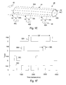
- FIG. 1D is a simplified graph that illustrates a portion of an output wavelength range for the laser source of FIG. 1A ;
- FIG. 1E is a simplified perspective view of one embodiment of a feedback assembly having features of the present invention.
- FIG. 1F is a simplified graph that illustrates the power directed to the laser source of FIG. 1A ;
- FIG. 2A is simplified top illustration in partial cut-away of another embodiment of a laser source having features of the present invention
- FIG. 2B is a simplified cut-away view taken on line 2 B- 2 B in FIG. 2A ;
- FIG. 3 is a simplified perspective view of another embodiment of a feedback assembly having features of the present invention.
- FIG. 4 is a simplified perspective view of still another embodiment of a feedback assembly having features of the present invention.
- FIG. 5 is simplified illustration of a sensor system having features of the present invention and an emitting gas
- FIG. 6 is a simplified illustration of another embodiment of a sensor system having features of the present invention.
- FIG. 1A is a simplified top illustration, in partial cut-away, and FIGS. 1B and 1C are cut-away views of a laser source 10 that is suited for imaging, locating, detecting, and/or identifying a substance (e.g. an emitting gas not shown in FIGS. 1A-1C ) and/or other industrial or testing applications.
- the laser source 10 is designed to rapidly and accurately generate an output beam 12 that consists of one or more sets of sequential, wavelength specific output pulses of light that span a predetermined output wavelength range.
- the output beam 12 traverses along an output beam axis 12 A and originates from the same laser source 10 .
- the output beam 12 from the laser source 10 can be specifically tailored to target the absorption features of the substance of interest. Further, in certain embodiments, because of the unique design disclosed herein, the laser source 10 can be extremely compact, hand-held, lightweight, stable, rugged, small, self-contained, and portable.
- the laser source 10 is designed so that the set of output pulses of light have a center wavelength in the mid-infrared range of approximately 2-20 micrometers.
- the laser source 10 can be designed to generate an output beam 12 consisting of a set of sequential, specific output pulses of light that span the entire or just a portion of the mid-infrared range.
- the laser source 10 is particularly useful in absorption spectroscopy applications since many gases of interest have strong, unique absorption signatures within the mid-infrared range.
- the laser source 10 can be designed to generate one or more output pulses of light having a center wavelength of greater than or lesser than 2-20 micrometers.
- a number of Figures include an orientation system that illustrates an X axis, a Y axis that is orthogonal to the X axis, and a Z axis that is orthogonal to the X and Y axes. It should be noted that these axes can also be referred to as the first, second and third axes.
- the laser source 10 is uniquely designed to provide a relatively high output power, accurate output beam 12 including a set of output pulses of light that span a relatively large wavelength range, in a very fast time (e.g. approximately ten milliseconds or less).
- the laser source 10 is well suited for use with a spectrometer to provide a broad spectral sweep in a fast time because the results of the spectrometer are less influenced by heat, wind, dust, or other unstable atmospheric conditions that can distort the delivery and return paths of the output beam 12 .
- the design of the laser source 10 can be varied to achieve the desired type of gas detection or other usage of the laser source 10 .
- the laser source 10 includes a source frame 14 , a plurality of lasers 16 , 18 , 20 , a power source 22 , a temperature controller 24 , a beam redirector assembly 26 , a wavelength dependent (“WD”) feedback assembly 28 , a position detector 30 , and a control system 32 that cooperate to generate the output beam 12 .
- the design of each of these components can be varied pursuant to the teachings provided herein. Further, it should be noted that the laser source 10 can be designed with more or fewer components than described herein.
- the source frame 14 supports at least some of the components of the laser source 10 .
- the lasers 16 , 18 , 20 , the power source 22 , the temperature controller 24 , the beam redirector assembly 26 , the WD feedback assembly 28 , the position detector 30 , and the control system 32 are each fixedly secured, in a rigid arrangement to the source frame 14 ; and (ii) the source frame 14 maintains these components in precise mechanical alignment to achieve the desired wavelength of each of the output pulses of the set.
- the laser control system 32 , the power source 22 , and the temperature controller 24 can be secured to source frame 14 . With this design, all of the critical components are fixed to the source frame 14 in a stable manner, and the laser source 10 can be self-contained and extremely portable.
- the power source 22 , the temperature controller 24 , and/or the laser control system 32 can be separate from and external to the source frame 14 .
- the source frame 14 includes a rigid mounting base 34 , a cover 36 that encloses the components of the laser source 10 , and a window 38 that allows the output beam 12 to exit the cover 36 .
- the source frame 14 can be designed without the cover 36 , without the window 38 , and/or can have a configuration different from that illustrated in the Figures.
- the mounting base 34 provides a rigid platform for fixedly mounting the lasers 16 , 18 , 20 , the beam redirector assembly 26 , and the feedback assembly 28 .
- the mounting base 34 is illustrated as being generally rectangular plate shaped.
- the mounting base 34 is a single mechanical ground plane that provides structural integrity to the laser source 10 .
- the mounting base 34 can have a configuration that is different than that illustrated in Figures.
- the mounting base 34 is made of rigid material that has a relatively high thermal conductivity. In one non-exclusive embodiment, the mounting base 34 has a thermal conductivity of at least approximately 170 watts/meter K. With this design, in addition to rigidly supporting the components of the laser source 10 , the mounting base 34 also readily transfers heat away from the lasers 16 , 18 , 20 to the temperature controller 24 .
- the mounting base 34 can be fabricated from a single, integral piece of copper, copper-tungsten or other material having a sufficiently high thermal conductivity. The one piece structure of the mounting base 34 maintains the fixed relationship of the components mounted thereto and contributes to the small size and portability of the laser source 10 .
- the cover 36 is shaped somewhat similar to an inverted, open rectangular box.
- the cover 36 can be hermetically sealed to the mounting base 34 in an air tight manner.
- the environment enclosed by the cover 36 can be filled with a fluid such as nitrogen or an air/nitrogen mixture to keep out moisture and humidity; or it can be subjected to a vacuum.
- the controlled environment keeps out gases that can absorb infrared light, such as water and carbon dioxide, or the substance that is being detected.
- the overall size of the source frame 14 is relatively small so that the laser source 10 is very portability.
- the source frame 14 can have dimensions of approximately 20 centimeters (height) by 20 centimeters (width) by 20 centimeters (length) (where length is taken along the propagation direction of the laser beam) or less, and more preferably, the source frame 14 has dimensions of approximately 3 centimeters (height) by 4 centimeters (width) by 5 centimeters (length). Still alternatively, the source frame 14 can have dimensions of less than approximately 10 millimeters (height) by 25 millimeters (width) by 30 millimeters.
- the number of the lasers 16 , 18 , 20 can be varied pursuant to the teachings provided herein to achieve the desired output wavelength range.
- the laser source 10 includes three, spaced apart lasers 16 , 18 , 20 .
- the laser source 10 can be designed to include more than three or fewer than three lasers 16 , 18 , 20 .
- each of the lasers 16 , 18 , 20 can be varied pursuant to the teachings provided herein to achieve the desired predetermined wavelength range.
- each of the lasers 16 , 18 , 20 is somewhat similar in design.
- each of the lasers 16 , 18 , 20 can be specifically designed to generate a different portion of the predetermined wavelength range.
- the number of lasers 16 , 18 , 20 can be increased, with each laser 16 , 18 , 20 generating a separate portion of the predetermined wavelength range.
- power is directed to the first laser 16 to sequentially generate a first beam 16 A that consists of a plurality of first pulses of light;
- power is directed to the second laser 18 to sequentially generate a second beam 18 A that consists of a plurality of second pulses of light;
- power is directed to the third laser 20 to sequentially generate a third beam 20 that consists of a plurality of third pulses of light.
- 1D is a graph that illustrates (i) a wavelength profile versus time for a couple of first pulses of the first beam 16 A; (ii) a wavelength profile versus time for a couple of second pulses of the second beam 18 A; (iii) a wavelength profile versus time for a couple of third pulses of the third beam 20 A; and (iv) a wavelength profile for the resulting output beam 12 .
- the first laser 16 is designed so that the center wavelength of each of the plurality of first pulses of light is in a first range portion of the predetermined wavelength range;
- the second laser 18 is designed so that the center wavelength of each of the plurality of second pulses of light 18 A is in a second range portion of the predetermined wavelength range;
- the third laser 20 is designed so that the center wavelength of each of the plurality of third pulses of light 20 A is in a third range portion of the predetermined wavelength range.
- the desired predetermined wavelength range can be varied to suit the absorption profile/detection range of the substance being located and/or identified.
- a relatively large wavelength range is necessary to achieve specificity when analyzing mixtures of chemicals.
- the resolution between different spectral signatures for different chemicals increases as the spectral range that is being analyzed is increased, thus allowing individual components to be detected.
- the predetermined wavelength range includes (i) the first range portion of approximately 3.2-3.7 microns; (ii) the second range portion of approximately 6-10 microns; and (iii) a third range portion of approximately 10-12 microns.
- the first laser 16 generates the first beam 16 A that consists of a set of sequential, specific, different center wavelength, first pulses of light that span the 3.2-3.7 micron range;
- the second laser 18 generates the second beam 18 A that consists a set of sequential, specific, different center wavelength, second pulses of light that span the 6-10 micron range;
- the third laser 20 generates the third beam 20 A that consists of a set of sequential, specific, different center wavelength, third pulses of light that span the 10-12 micron range.
- the lasers 16 , 18 , 20 can be designed so that (i) all of the range portions partly overlap, (ii) one or more of the range portions cover another part the mid-infrared spectrum, and/or (iii) one or more of the range portions is larger or smaller than described above.
- the first beam 16 A has a first, first pulse of light having a center wavelength of 3.2 microns, and a second, first pulse of light having a center wavelength of 3.25 microns;
- the second beam 18 A has a first, second pulse of light having a center wavelength of 6 microns and a second, second pulse of light having a center wavelength of 6.05 microns;
- the third beam 20 A has a first, third pulse of light having a center wavelength of 9 microns, and a second, third pulse of light having a center wavelength of 9.25 microns.
- the first laser 16 includes a first gain medium 16 B, a first cavity optical assembly 16 C, and a first output optical assembly 16 D
- the second laser 18 includes a second gain medium 18 B, a second cavity optical assembly 18 C, and a second output optical assembly 18 D
- the third laser 20 includes a third gain medium 20 B, a third cavity optical assembly 20 C, and a third output optical assembly 20 D.
- each gain medium 16 B, 18 B, 20 B directly emits the respective beams 16 A, 18 A, 20 A without any frequency conversion.
- the gain mediums 16 B, 18 B, 20 B can be a Quantum Cascade (QC) gain medium, an Interband Cascade (IC) gain medium, or a mid-infrared diode.
- the first laser 16 can utilize a mid-infrared diode
- the other two lasers 18 , 20 can utilize Quantum Cascade gain mediums.
- another combination of the gain mediums can be utilized.
- each of the laser 16 , 18 , 20 can utilize a Quantum Cascade gain medium.
- each Quantum Cascade gain medium 16 B, 18 B, 20 B is approximately 2 millimeters by 0.5 millimeters, by 90 micrometers.
- Suitable Quantum Cascade gain mediums 16 B, 18 B, 20 B can be purchased from Bru Lasers, located in Switzerland.
- each gain medium 16 B, 18 B, 20 B can be altered to achieve the desired output frequency range for each gain medium 16 B, 18 B, 20 B.
- the first gain medium 16 B can be fabricated to have a tuning range that matches the first range portion
- the second gain medium 18 B can be fabricated to have a tuning range that matches the second range portion
- the third gain medium 20 B can be fabricated to have a tuning range that matches the third range portion.
- the thickness of the wells/barriers of a Quantum Cascade gain medium determine the wavelength characteristic of the respective Quantum Cascade gain medium.
- fabricating a Quantum Cascade gain medium of different thickness enables production of the laser having different output frequencies within the MIR range.
- each gain medium 16 B, 18 B, 20 B includes (i) a first facet 40 A that faces the respective cavity optical assembly 16 C, 18 C, 20 C and the feedback assembly 28 , and (ii) a second facet 40 B that faces the output optical assembly 16 D, 18 D, 20 D.
- each gain medium 16 B, 18 B, 20 B emits from both facets.
- each first facet 40 A is coated with an anti-reflection (“AR”) coating
- each second facet 40 B is coated with a reflective coating.
- AR anti-reflection
- the AR coating allows light directed from the respective gain medium 16 B, 18 B, 20 B at the first facet 40 A to easily exit as a beam 16 A, 18 A, 20 A directed at the feedback assembly 28 ; and allows the light beam 16 A, 18 A, 20 A reflected from the feedback assembly 28 to easily enter the respective gain medium 16 B, 18 B, 20 B.
- the beams 16 A, 18 A, 20 A exit from the respective second facet 16 B and are redirected by the beam redirector assembly 26 to form the output beam 12 .
- the reflective coating on the second facet 16 B of each gain medium 16 B, 18 B, 20 B reflects at least some of the light 16 A, 18 A, 20 A that is directed at the second facet 16 B of each gain medium 16 B, 18 B, 20 B back into the respective gain medium 16 B, 18 B, 20 B.
- the AR coating can have a reflectivity of less than approximately 2 percent, and the reflective coating can have a reflectivity of between approximately 2-95 percent.
- the reflective coating on the second facet 40 B of the first gain medium 16 B acts as an output coupler (e.g. a first end) of a first external cavity 16 E;
- the reflective coating on the second facet 40 B of the second gain medium 18 B acts as an output coupler (e.g. a first end) of a second external cavity 18 E;
- the reflective coating on the second facet 40 B of the third gain medium 20 B acts as an output coupler (e.g. a first end) of a third external cavity 20 E.
- the feedback assembly 28 is spaced apart from the gain medium 16 B, 18 B, 20 B, and defines a second end of each external cavity 16 E, 18 E, 20 E.
- the term external cavity 16 E, 18 E, 20 E is utilized to designate that the feedback assembly 28 is positioned outside of the respective gain medium 16 B, 18 B, 20 B. In FIGS. 1A-1C , the respective external cavity 16 E, 18 E, 20 E is not external to the source frame 14 .
- the first cavity optical assembly 16 C is positioned between the first gain medium 16 B and the feedback assembly 28 along a first lasing axis 16 F (along the X axis in FIG. 1A ), and collimates and focuses the first beam 16 A that passes between these components.
- the second cavity optical assembly 18 C is positioned between the second gain medium 18 B and the feedback assembly 28 along a second lasing axis 18 F (along the X axis in FIG. 1A ), and collimates and focuses the second beam 18 A that passes between these components.
- the third cavity optical assembly 20 C is positioned between the third gain medium 20 B and the feedback assembly 28 along a lasing axis 20 F (along the X axis in FIG. 1A ), and collimates and focuses the third beam 20 A that passes between these components.
- each cavity optical assembly 16 C, 18 C, 20 C can include one or more lens.
- the lens can be an aspherical lens having an optical axis that is aligned with the respective lasing axis 16 F, 18 F, 20 F.
- the lens has a relatively small diameter.
- the lens has a diameter of less than approximately 5 or 10 millimeters, and a focal length of approximately 1, 2, 3, 4, 5, 6, 7, 8, 9, 10, 11, 12, 13, 14, 15, 16, 17, 18, 19, or 20 mm and any fractional values thereof.
- the lens can comprise materials selected from the group of Ge, ZnSe, ZnS Si, CaF, BaF or chalcogenide glass.
- the lens may be made using a diamond turning or molding technique.
- the lens can be designed to have a relatively large numerical aperture (NA).
- NA numerical aperture
- the lens can have a numerical aperture of at least approximately 0.6, 0.7, or 0.8.
- the NA may be approximated by the lens diameter divided by twice the focal length.
- a lens diameter of 5 mm having a NA of 0.8 would have a focal length of approximately 3.1 mm.
- the first output optical assembly 16 D is positioned between the first gain medium 16 B and the beam redirector assembly 26 in line with the first lasing axis 16 F to collimate and focus the first beam 16 A that exits the second facet 40 B of the first gain medium 16 B.
- the second output optical assembly 18 D is positioned between the second gain medium 18 B and the beam redirector assembly 26 in line with the second lasing axis 18 F to collimate and focus the second beam 18 A that exits the second facet 40 B of the second gain medium 18 B.
- each output optical assembly 16 D, 18 D, 20 D can include one or more lens that are somewhat similar in design to the lens of the cavity optical assemblies 16 C, 18 C, 20 C.
- the power source 22 provides electrical power to the gain mediums 16 B, 18 B, 20 B, the control system 32 , and the temperature controller 24 .
- the power source 22 is a battery that is secured to the source frame 14 .
- the battery can be nickel metal hydrate.
- the power source 22 can be external to the source frame 14 .
- the power source 22 can be an external battery or a power outlet.
- the gain mediums 16 B, 18 B, 20 B generate quite a bit of heat. Accordingly, the temperature controller 24 can be an important component that is needed to remove the heat, thereby permitting long lived operation of the laser source 10 and consistent optical output power.
- the temperature controller 24 can be used to control the temperature of the gain mediums 16 B, 18 B, 20 B, the mounting base 34 , and/or one or more of the other components of the laser source 10 . Further, by controlling the temperature, the temperature controller 24 can be used to maintain the relative position of the gain mediums 16 B, 18 B, 20 B, and the other components of the laser source 10 .
- the temperature controller 24 includes a thermoelectric cooler and a temperature sensor (not shown).
- the thermoelectric cooler may be controlled to effect cooling or heating depending on the polarity of the drive current thereto.
- the thermoelectric cooler is fixed to the bottom of the mounting base 34 so that the thermoelectric cooler is in direct thermal communication with the mounting base 34 , and so that the thermoelectric cooler can provide additional rigidity and support to the mounting base 34 .
- the top of the thermoelectric cooler is approximately the same size as the bottom surface of the mounting base 34 . This promotes good heat transfer between the thermoelectric cooler and the mounting base 34 , and maximizes the support for the mounting base 34 provided by the thermoelectric cooler.
- the thermoelectric cooler can be fixedly secured to the mounting base with bolts, epoxy, welding, solder or other suitable means.
- thermoelectric cooler may be attached between the thermoelectric cooler and the mounting base 34 .
- the temperature sensor provides temperature information that can be used to control the operation of the thermoelectric cooler so that the thermoelectric cooler can maintain the desired temperature of the laser source 10 .
- the temperature sensor can be positioned on the mounting base 34 near the gain mediums 16 B, 18 B, 20 B and can be used to monitor the temperature of the gain mediums 16 B, 18 B, 20 B.
- fine tuning of the beams 16 A, 18 A, 20 A can be achieved by controlling the temperature of the respective gain medium 16 B, 18 B, 20 B, such as by changing the DC bias current.
- temperature tuning is relatively narrow and may be used to vary the wavelength by approximately 1-2 gigahertz/Kelvin which is typically less than 0.01% of the peak emission wavelength.
- the source frame 14 can be mounted to a heat sink (not shown) inside a larger housing (not shown) which may also contain additional equipment including cooling fans and vents to further remove the heat generated by the operation of the laser source 10 .
- the beam redirector assembly 26 redirects and combines the beams 16 A, 18 A, 20 A to form the output beam 12 that consists of the plurality of output pulses of light that cover the entire predetermined spectral wavelength range.
- the beam redirector assembly 26 redirects the first, second, and third beams 16 A, 18 A, 20 A so that they are approximately coaxial when exiting the laser 10 .
- the beam redirector assembly 26 includes (i) a reflector 42 A (e.g.
- the first beam splitter 42 B can be a bandpass filter that passes light at the wavelength of the first beam 16 A and that reflects light at the wavelength of the second beam 18 A; and (ii) the second beam splitter 42 C can be a bandpass filter designed to pass light at the wavelength of the first beam 16 A and the second beam 18 A, and to reflect light at the wavelength of the third beam 20 A.
- the beam redirector assembly 26 can have a design different than that illustrated in FIG. 1A .
- the beam redirector assembly 26 can include one or more beam splitters that pass a beam having one polarization and reflect a beam having another polarization.
- the first beam 16 A and the second beam 18 A can have a vertical polarization and the third beam 20 A can have an orthogonal polarization.
- the first beam splitter 42 B can be a bandpass filter that passes light at the wavelength of the first beam 16 A and that reflects light at the wavelength of the second beam 18 A; and (ii) the second beam splitter 42 C can be a filter designed to pass light having a vertical polarization, and reflect light having an orthogonal polarization.
- the common feedback assembly 28 (i) reflects the first beam 16 A back to the first gain medium 16 B, and is used to precisely select and adjust the lasing frequency of the first external cavity 16 E and the wavelength of the first pulses of light; (ii) reflects the second beam 18 A back to the second gain medium 18 B, and is used to precisely select and adjust the lasing frequency of the second external cavity 18 E and the wavelength of the second pulses of light; and (iii) reflects the third beam 20 A back to the third gain medium 20 B, and is used to precisely select and adjust the lasing frequency of the third external cavity 20 E and the wavelength of the third pulses of light.
- the common feedback assembly 28 is used to feed back to the respective gain medium 16 B, 18 B, 20 B a relatively narrow band wavelength which is then amplified in the respective gain medium 16 B, 18 B, 20 B.
- the beams 16 A, 18 A, 20 A may be tuned with the feedback assembly 28 without adjusting the respective gain medium 16 B, 18 B, 20 B.
- the feedback assembly 28 dictates what wavelength will experience the most gain in each laser 16 , 18 , 20 , and thus dominate the wavelength of the beams 16 A, 18 A, 20 A.
- the feedback assembly 28 includes a common redirector 44 , a feedback mover 46 , and a grating assembly 48 that cooperate to rapidly adjust the lasing frequency of the external cavity 16 E, 18 E, 20 E and the wavelength of each of the beams 16 A, 18 A, 20 A.
- the size, shape, and design of each of these components can be varied pursuant to the teachings provided herein.
- FIG. 1E is a simplified perspective view of the common redirector 44 , the feedback mover 46 , and the grating assembly 48 .
- the common redirector 44 redirects the first, second, and third beams 16 A, 18 A, 20 A that exit the first facet 40 A (illustrated in FIG. 1A ) of the gain mediums 16 B, 18 B, 20 B (illustrated in FIG. 1A ) towards the grating assembly 48 , and redirects the first, second, and third beams 16 A, 18 A, 20 A reflected off of the grating assembly 48 back to the respective gain mediums 16 B, 18 B, 20 B.
- the common redirector 44 includes one or more reflectors 44 A (e.g.
- the common redirector 44 is a multi-faceted mirror that includes eight mirrors 44 A that are secured to a multi-sided redirector housing 44 B that has an octagonal shaped cross-section.
- the common redirector 44 can include more than eight or fewer than eight mirrors 44 A.
- the feedback mover 46 continuously moves the common redirector 44 to quickly adjust (i) a first angle of incidence ⁇ 1 of the first beam 16 A on the grating assembly 48 ; (ii) a second angle of incidence ⁇ 2 of the second beam 18 A on the grating assembly 48 ; and (iii) a third angle of incidence ⁇ 3 of the third beam 20 A on the grating assembly 48 .
- the feedback mover 46 can continuously rotate the common redirector 44 about the redirector axis 44 C.
- the feedback mover 46 can be a rotary motor that rotates at between approximately five (5) to fifty (50) revolutions per second. Stated in another fashion, in alternative non-exclusive embodiments, the feedback mover can rotate at approximately 5, 10, 20, 30, 40, or 50 revolutions per second.
- the assembly can be designed to rotate at a higher or slower rate than described above.
- the grating assembly 48 (i) reflects the first beam 16 A, and is used to precisely select and adjust the wavelength of the first beam 16 A; (ii) reflects the second beam 18 A, and is used to precisely select and adjust the wavelength of the second beam 18 A; and (iii) reflects the third beam 20 A, and is used to precisely select and adjust the wavelength of the third beam 20 A.
- the grating assembly 48 includes (i) a fixed first diffraction grating 48 A that selects the wavelength of the first beam 16 A; (ii) a fixed, second diffraction grating 48 B that selects the wavelength of the second beam 18 A; and (iii) a fixed third diffraction grating 48 C that selects the wavelength of the third beam 20 A.
- each of the diffraction gratings 48 A, 48 B, 48 C has wavelength dependent reflectivity.
- a typical diffraction grating 48 A, 48 B, 48 C includes a glass or polished metal reflector surface having a large number of very fine parallel grooves or slits. The pitches of each diffraction grating 48 A, 48 B, 48 C can be individually designed to achieve the desired tuning range for each individual laser 16 , 18 , 20 .
- the spinning reflectors 44 A direct the beams 16 A, 18 A, 20 A to the respective grating 48 A, 48 B, 48 C in a Littrow configuration.
- This accomplishes a fast sweep, with the advantage of multiple sweeps per motor revolution.
- the length of the redirector 44 can be extended as needed to tune more than three lasers 16 , 18 , 20 .
- the common reflector 44 naturally synchronizes the spectral sweep of each laser 16 , 18 , 20 to the same fast time scale over the same time range.
- the tuning of two or more lasers 16 , 18 , 20 can be easily synchronized.
- the gain mediums 16 B, 18 B, 20 B, and the diffraction gratings 48 A, 48 B, 48 C can each be individually designed so that each laser 16 , 18 , 20 has access to a different selected tuning range.
- rotation of the redirector 44 changes the first angle of incidence ⁇ 1 of the first beam 16 A on the first diffraction grating 48 A to preferentially select a single wavelength which is the first order diffracted light from the grating 48 A; (ii) changes the second angle of incidence ⁇ 2 of the second beam 18 A on the second diffraction grating 48 B to preferentially select a single wavelength which is the first order diffracted light from the grating 48 B; and (iii) changes the third angle of incidence ⁇ 3 of the third beam 20 A on the third diffraction grating 48 C to preferentially select a single wavelength which is the first order diffracted light from the grating 48 C.
- the feedback assembly 28 controls the center wavelength of each beam 16 A, 18 A, 20 A to within approximately 0.1, 0.01, 0.001, or 0.0001 micrometers.
- each of the beams 16 A, 18 A, 20 A has a relatively narrow line width.
- the laser source 10 can be designed so that the line width of one or more of the beams 16 A, 18 A, 20 A is less than approximately 5, 4, 3, 2, 1, 0.8, 0.5, or 0.1 cm-1. This provides more than adequate resolution for spectrally evaluation of many substances. For example, most spectrometers used for condensed phase spectroscopy have a resolution of 4 cm ⁇ 1 .
- the laser source 10 can be designed so that the line width of one or more of the beams 16 A, 18 A, 20 A is greater than approximately 7, 8, 9, or 10 cm-1.
- the spectral width of the beams 16 A, 18 A, 20 A can be adjusted by adjusting the cavity parameters of the external cavities 16 E, 18 E, 20 E.
- the spectral width of the beams 16 A, 18 A, 20 A can be increased or decreased by changing the focal length of the respective cavity optical assembly 16 C, 18 C, 20 C.
- FIG. 1B illustrates the redirector 44 in a first redirector position 50 A
- FIG. 1C illustrates that the redirector 44 has been rotated to a second redirector position 50 B.
- the first angle of incidence ⁇ 1 is greater when the redirector 44 is in the first redirector position 50 A than in the second redirector position 50 B.
- the first beam 16 A has a first center wavelength
- the redirector 44 is in the second redirector position 50 B
- the first beam 16 A has a second center wavelength that is different than the first center wavelength.
- the amount of difference in wavelength will depend upon (among other things) how much the first angle of incidence ⁇ 1 has changed and the characteristics of the first diffraction grating 48 A.
- the tuning of the wavelength of the beams 16 A, 18 A, 20 A is realized by rotating the redirector 44 and changing the angle of incidences ⁇ 1 , ⁇ 2 , ⁇ 3 .
- the feedback mover 46 can move the redirector 44 to a plurality of alternative redirector positions 50 A, 50 B (only two are illustrated in FIGS. 1B , 1 C) to quickly adjust the angle of incidences ⁇ 1 , ⁇ 2 , ⁇ 3 .
- the laser 10 In many spectroscopic applications, it is desirable to tune over the entire range of the laser 10 in a time that is short compared to the environment being evaluated. For example, if the laser 10 is used to target gases in the open air, the target gases are susceptible to intensity fluctuations due to atmospheric turbulence. In order to approximately “freeze” the atmosphere and acquire a spectrum with a substantially unvarying intensity profile, it is necessary to scan the laser 10 faster than the atmospheric turbulence.
- the feedback mover 46 moves the redirector 44 to generate the spectrum of output pulses of the output beam 12 in less than approximately one, two, three, four, five, seven or ten milliseconds. This allows for the acquisition of a complete molecular spectrum before the measurement volume significantly changes due to conditions such as atmospheric turbulence.
- the position detector 30 accurately measures and monitors the position of at least a portion of the feedback assembly 28 and provides a position signal to the control system 32 that relates to the position of at least a portion of the feedback assembly 28 . Stated in another fashion, the position detector 30 can generate a separate position signal that relates to each position of the moving redirector 44 . For example, the position detector 28 can generate a first position signal when the redirector 44 is at the first device position 50 A (illustrated in FIG. 1B ) and a second position signal when the redirector 44 is at the second device position 50 B (illustrated in FIG. 1C ).
- the position signals relate to the angles of incidence ⁇ 1 , ⁇ 2 , ⁇ 3 of the first, second, and third beams 16 A, 18 A, 20 A on the grating assembly 48 .
- the position detector 30 can be an optical encoder, or a Hall type sensor.
- the position detector 30 is an optical encoder that includes a plurality of encoder marks 52 (a few are illustrated in FIG. 1E ) on the redirector housing 44 B, and an optical reader 54 .
- the optical reader 54 can monitor the encoder marks 52 and provide a position signal that relates to the position of the redirector 44 relative to the beams 16 A, 18 A, 20 A, and values of the angle of incidences ⁇ 1 , ⁇ 2 , ⁇ 3 .
- the control system 32 controls the operation of the laser source 10 including the electrical power to the feedback mover 46 , the electrical power that is directed to the gain mediums 16 B, 18 B, 20 B (e.g. controls the gain mediums 16 B, 18 B, 20 B by controlling the electron injection current), and the temperature controller 24 .
- the control system 32 can include one or more processors.
- the control system 32 is rigidly and fixedly mounted to the source frame 14 so that the laser source 10 is portable and rugged.
- the control system 32 can be external to the source frame 14 .
- control system 32 receives the position signals from the position detector 30 and directs power to the feedback mover 46 to continuously move the redirector 44 . Further, the control system 32 can direct power to the gain mediums 16 B, 18 B, 20 B in a fashion that minimizes heat generation in, and power consumption of the gain mediums 16 B, 18 B, 20 B while still achieving the desired set of output pulses. For example, to realize low power consumption, the power to the gain mediums 16 B, 18 B, 20 B can be pulsed on and off.
- Pulsing of the power to the gain mediums 16 B, 18 B, 20 B not only reduces power consumption, it also reduces the thermal load produced by the laser 10 , and allows higher temperature operation such that more efficient above-ambient temperature control can be used to stabilize the laser 10 .
- the benefits of running the laser 10 in pulsed mode extend to a reduction in size and complexity due to the simpler and more robust above-ambient temperature control and battery operation. This in turn aids in creating a truly portable laser 10 by reducing the size and weight, and enabling cordless battery operation. It also enables more compact and rugged lasers 10 to be built that can be field-deployed.
- the control system 32 directs the pulses of power to the gain mediums 16 B, 18 B, 20 B based on the position signal received from the position detector 30 .
- the control system 32 can direct (i) a pulse of power to the first gain medium 16 B every time the optical reader 54 reads a first predetermined number of encoder marks 52 ; (ii) a pulse of power to the second gain medium 18 B every time the optical reader 54 reads a second predetermined number of encoder marks 52 ; and (iii) a pulse of power to the third gain medium 20 B every time the optical reader 54 reads a third predetermined number of encoder marks 52 .
- the pulses to each gain medium 16 B, 18 B, 20 B is synchronized with respect to the position detector 30 , and multiplexed with respect to each other to allow the pulse train to be decoded by one detector.
- control system 32 can sequentially direct a pulse of power to each gain medium 16 B, 18 B, 20 B at each of the plurality of rotational positions so that the laser source 10 generates the set of output pulses of the output beam 12 .
- control system 32 can direct a pulse of power to one of the gain mediums 16 B, 18 B, 20 B upon receipt of each new position signal.
- the specific wavelength of the output pulses of the output beam 12 will not be influenced by variations in speed of the motor 48 .
- the pulsing of the power to the gain mediums 16 B, 18 B, 20 B allows the laser pulses to be tied directly to the angular rotation by employing a phase-locked-loop (PLL) technique where the position signals from the position detector 30 are up-converted in frequency and phase locked to the angular signals to allow the pulses of power to be fired at precise angular increments that are well characterized. These angles for each power pulse can then be converted to an accurate wavelength scale for the recorded chemical spectra.
- PLL phase-locked-loop
- Accuracy and sensitivity are also enabled by using boxcar integration techniques with the position signals to allow the high-frequency pulsing of the laser to be analyzed in real time. This is necessary to use the full spectral range of the laser even as it is rapidly tuning.
- FIG. 1F illustrate one, non-exclusive embodiment of the timing of how the control system 32 (not shown in FIG. 1F ) can direct power pulses to the gain mediums 16 B, 18 B, 20 B (not shown in FIG. 1F ).
- a first power profile 55 A represents the power pulses directed to the first gain medium 16 B
- a second power profile 55 B represents the power pulses directed to the second gain medium 18 B
- a third power profile 55 C represents the power pulses directed to the third gain medium 20 B
- an overall power profile 55 D represents the power pulses directed to the three gain mediums 16 B, 18 B, 20 B.
- the control system 32 sequentially directs the maximum power to each of the gain mediums 16 B, 18 B, 20 B. More specifically, moving from left to right in FIG. 1F , the control system 12 (i) first directs a pulse of power to the third gain medium 20 B, (ii) next, directs a pulse of power to the second gain medium 18 B, (iii) subsequently directs a pulse of power to the first gain medium 16 B, and (iv) next repeats the sequence again. Thus, in this embodiment, the control system 32 sequentially pulses the power to the gain mediums 16 B, 18 B, 20 B.
- the multiplexed pulsing scheme has a pulse width of approximately two hundred nanoseconds and a repetition rate of approximately 55 kHz for each of the gain mediums 16 B, 18 B, 20 B. This provides an approximately eleven percent duty cycle for each gain mediums 16 B, 18 B, 20 B, with enough pulse width to provide spectral infill to reduce mode noise contributions to tuning.
- the fully multiplexed pulse sequence is densely packed, but can be used for fast digitization and boxcar integration for demultiplexing.
- the control system 32 can direct pulses of power to one or more of the gain mediums 16 B, 18 B, 20 B at a different pulse width or repetition rate than illustrated in FIG. 1F .
- control system 30 can control each pulse of power to have a duration of approximately 3, 4, 5, 10, 25, 50, 75, 100, 150, 200, 300, 400, 500, 600 or 700 nanoseconds. Further, the control system 32 can direct a different shaped power profile with different power levels to each of the gain mediums 16 B, 18 B, 20 B.
- the laser source 10 can be calibrated using a wavelength measurement device 56 during manufacturing of the laser source 10 . More specifically, with the laser source 10 activated, the feedback mover 46 can be used to change the angles of incidence ⁇ 1 , ⁇ 2 , ⁇ 3 , while monitoring position of the redirector 44 with the position detector 30 , and wavelength of the output pulses of the output beam 12 with the wavelength measurement device 56 . With this design, each position signal of the position detector 30 can be corresponded to a measured center wavelength of one of the output pulses of output beam 12 . Stated in another fashion, the control system 30 can determine a center wavelength of the output pulses of the output beam 12 based on the position signal.
- the control system 32 utilizes field a programmable gate array (“FPGA”) to control the pulses of power to lasers 16 , 18 , 20 and the rotation of the redirector 44 .
- FPGA field a programmable gate array
- This FPGA can be used for subsequent high speed (50 MHz) digitization of the reference and signal detectors, then real-time box car integration of the pulsed signals to construct spectral sweeps.
- the control system 32 can include an embedded microprocessor that takes this data from the FPGA to assemble spectra, which can then relayed to an external laptop (not shown in FIG. 1A ) via a fast USB connection. Subsequently, the spectra can be analyzed and fit in real time to determine chemical composition and concentration through the software.
- the multiplexed swept laser 10 requires one additional degree of synchronization.
- the lasers 16 , 18 , 20 must be temporally multiplexed.
- power is directed to the three lasers 16 , 18 , 20 so that the lasers 16 , 18 , 20 are fired in sequence.
- the master pulse sequence is controlled by the FPGA, using the position signals from the position detector 30 to lock the pulsing to the tuning. This way, it is possible to demultiplex each laser 16 , 18 , 20 signal in the FPGA after the detector signal is sent through the fast (e.g. 50 MHz) digitizer.
- the three separate lasers 16 , 18 , 20 spectral sweeps can then be assembled in the microprocessor and stitched together in the software to provide one complete spectrum.
- the multiplexed swept laser source 10 has a single reference detector 58 that picks off a portion of the multiplexed beam 12 .
- This reference detector 58 signal is digitized, boxcar averaged, and demultiplexed in the FPGA and microprocessor to construct a reference power level for all wavelengths and tuning ranges accessed by the multiplexed swept laser 10 .
- This signal is used together with the output beam 12 that is directed at the substrate being evaluated, either in transmission or reflection, and a signal detector that is also digitized and processed the same way as the reference detector 58 .
- the signal and reference data consist of optical power vs. wavelength, and can be used to construct an absorption spectrum. Further analysis of this spectrum is used to identify and detect different chemicals through their unique spectroscopic fingerprints.
- FIG. 2A is simplified top illustration, in partial cut-away, of another embodiment of a laser source 210 having features of the present invention.
- the laser source 210 includes a source frame 214 , a plurality of lasers 216 , 218 , 220 , a power source 222 , a wavelength dependent feedback assembly 228 , a position detector 230 , and a control system 232 that are similar to the corresponding components described above.
- the beam redirector assembly 226 is slightly different. More specifically, in this embodiment, the beam redirector assembly 226 includes (i) a first reflector 242 A (e.g.
- a mirror the redirects the first beam 216 A approximately ninety degrees so the first beam 216 A is directed along the Y axis;
- a second reflector 242 B e.g. a mirror
- a third reflector 242 C e.g. a mirror
- a fourth reflector 242 D e.g.
- the beam redirector assembly 226 redirects the beams 216 A, 218 A, 220 A so that they are approximately coaxial with an output beam axis 212 A of the output beam 212 exiting the laser source 210 .
- the first, second, and third beams 216 A, 218 A, 220 A can be combined without loss of optical power with this tiling scheme.
- FIG. 2B is a simplified cut-away illustration of the first, second, and third beams 216 A, 218 A, 220 A just after the first, second, and third beams 216 A, 218 A, 220 A are brought towards each other to form the output beam 212 .
- each of the first, second, and third beams 216 A, 218 A, 220 A has a size at the laser 210 of approximately three millimeters in diameter. If the three beams 216 A, 218 A, 220 A are packed in a parallel configuration, with approximately a one millimeter separation, the beams 216 A, 218 A, 220 A will overlap at distances greater than approximately one meter from the laser 210 .
- FIG. 3 is a simplified perspective view of another embodiment of a WD feedback assembly 328 .
- the feedback assembly 328 includes a grating assembly 344 , and a feedback mover 346 that cooperate to rapidly adjust the wavelength of each of the first, second, and third beams 316 A, 318 A, 320 A.
- the common grating assembly 344 includes one or more diffraction gratings 344 A, and a housing 344 B that retains the one or more diffraction gratings 344 A.
- the one or more diffraction gratings 344 A are rotated by the feedback mover 346 about an axis 344 C.
- the number of diffraction gratings 344 A can be varied.
- the feedback assembly 328 is a multi-faceted grating that includes eight diffraction gratings 344 A that are secured to a multi-sided housing 344 B that has an octagonal shaped cross-section.
- the feedback assembly 328 can include more than eight or fewer than eight diffraction gratings 344 A.
- the feedback mover 346 continuously moves the diffraction gratings 344 A to quickly adjust (i) a first angle of incidence of the first beam 316 A on the grating assembly 344 to adjust the wavelength of the first beam 316 A; (ii) a second angle of incidence of the second beam 318 A on the grating assembly 344 to adjust the wavelength of the second beam 318 A; and (iii) a third angle of incidence of the third beam 320 A on the grating assembly 344 to adjust the wavelength of the third beam 320 A.
- the spinning gratings 344 A accomplish a fast sweep, with the advantage of multiple sweeps per motor revolution.
- the length of the grating assembly 344 can be extended as needed to tune more than three lasers. Further, the grating assembly 344 naturally synchronizes the spectral sweep of each laser to the same fast time scale over the same time range.
- FIG. 4 is a simplified perspective view of another embodiment of a WD feedback assembly 428 .
- the feedback assembly 428 includes a grating assembly 444 , and a feedback mover 446 that cooperate to rapidly adjust the wavelength of each of the first, second, and third beams 416 A, 418 A, 420 A.
- the common grating assembly 444 includes a single diffraction grating 444 A, and a housing 444 B that retains the diffraction grating 444 A.
- the diffraction grating 444 A is rotated by the feedback mover 446 about an axis 444 C.
- the feedback mover 446 continuously moves the diffraction grating 444 A to quickly adjust (i) a first angle of incidence of the first beam 416 A on the grating assembly 444 to adjust the wavelength of the first beam 416 A; (ii) a second angle of incidence of the second beam 418 A on the grating assembly 444 to adjust the wavelength of the second beam 418 A; and (iii) a third angle of incidence of the third beam 420 A on the grating assembly 444 to adjust the wavelength of the third beam 420 A.
- the spinning grating 444 A still accomplishes a fast sweep.
- the length of the grating assembly 444 can be extended as needed to tune more than three lasers. Further, the grating assembly 444 naturally synchronizes the spectral sweep of each laser to the same fast time scale over the same time range.
- a full sweep of spectrum can be performed in approximately eight milliseconds.
- the laser pulses can be synchronized with the feedback assembly to provide a stable wavelength axis.
- This technology can be incorporated with a sensor to provide a fully-integrated spectrometer used for both gas- and condensed-phase measurements.
- FIG. 5 is simplified illustration of a substance sensor system 560 having features of the present invention and a substance 562 e.g. an emitting gas.
- the sensor system 560 includes (i) a laser source 510 that illuminates the area near the emitting gas 562 , and (ii) an imager 564 (i.e. an infrared camera) that captures real-time, high resolution thermal images 566 of the emitting gas 562 that can be displayed or recorded for future viewing.
- the sensor system 560 is useful for locating substances 562 (i.e. leaks) in the oil, gas, utility, chemical industries, as well as locating emitting gas 562 for homeland security. Further, the sensor assembly 560 can be used to identify and locate IEDs.
- the sensor system 560 can be extremely accurate, compact, hand-held, lightweight, stable, rugged, small, self-contained, and portable.
- the type of substance 562 detectable by the sensor system 560 can include any gas 562 having molecules that absorb (“absorption features”) in the MIR range.
- gases 562 having absorption features in the MIR range that can be detected includes, but is not limited to, (i) sulfur hexafluoride (SF6), (ii) Acetylchloride, (iii) Ethylene, (iv) Freon (such as dichlorodifluoromethane), (v) Propenal, (vii) Tricholorethylene, (viii) methane (CH4), (ix) ethylene (C2H4), (x) ethane (C2H6), (xi) hydrogen chloride (HCl), (xii) ammonia (NH3), (xiii) nitrous oxide (NO), (xiv) hydrazine (N2H4), and (xv) monomethyl hydrazine (MMH).
- a non-exclusive list of possible sources 568 of the emitting gas 562 includes IEDs, containers, power plants, industrial equipment, gas lines, storage tanks, and electrical equipment.
- the laser source 510 can be similar in design to the laser sources 10 , 210 described above.
- the laser source 510 can rapidly and accurately generate an output beam 512 consisting of one or more sets of sequential, wavelength specific output pulses that span a predetermined detection range (e.g. the mid-infrared range).
- the imager 564 captures the thermal image 566 of the gas 562 and the surrounding environment.
- the imager 564 is an infrared camera that provides real-time, high resolution thermal images 566 of the emitting gas 562 that can be displayed on a display 572 or recorded for future viewing.
- the display 572 is illustrated as being positioned away from the imager 564 .
- the display 572 can be a screen that is attached to the imager 564 .
- the imager 564 includes an image sensor 574 (illustrated in phantom), a filter assembly 576 (illustrated in phantom), a storage system 578 (illustrated in phantom), and an imager control system 580 .
- the image sensor 574 receives the light that passes through the filter assembly 576 and converts the light into electricity.
- suitable image sensors 574 can include microbolometers, quantum well infrared photodetectors, or thermal light valve technology sold by Redshift Systems Corporation, located in Burlington, Mass.
- the filter assembly 576 limits the wavelength of the light that is directed at the image sensor 574 .
- the filter assembly 576 can be designed to transmit all light in the MIR range, and block all light having a wavelength that is greater or lesser than the MIR range. With this design, the image sensor 574 responds primarily to desired wavelength, and ignores other background thermal emissions.
- the storage system 578 stores the various images.
- suitable storage systems 578 include flash memory, a floppy disk, a hard disk, or a writeable CD or DVD.
- the imager control system 580 is electrically connected to and controls the operation of the electrical components of the imager 564 .
- the imager control system 580 can include one or more processors and circuits and the imager control system 580 can be programmed to perform one or more of the functions described herein.
- the imager control system 580 receives information from the image sensor 574 and generates the image 566 . Additionally, or alternatively, the imager control system 580 can further enhance the image 566 with color or other features that will further identify the location or type of emitting gas 562 .
- the imager control system 580 can analyze the information from one or more images 566 to identify the one or more specific emitting gases 562 that are present and/or determine the quantity of one or more emitting gases 562 that are present.
- the imager 564 and the laser source 510 share a common housing.
- the imager 564 and the laser source 510 can have separate housings.
- the imager 564 can include a battery 582 (illustrated in phantom) for powering the imager 564 . This allows for the portable operation of the imager 564 in remote locations.
- the imager 564 and the laser source 510 can share a common battery, or the sensor system 560 can be connected with an electrical cord to a power outlet.
- the output beam 512 is directed at a background 584 near a possible site of a gas leakage.
- the imager 564 captures both backscattered light 586 (illustrated as arrows) that is reflected off of the background 584 and background radiation.
- the backscattered light 586 is highly attenuated. This produces a region of contrast or shadow 588 on the image 566 that corresponds to and clearly illustrates the emitting gas 562 .
- the background 584 can be any object that reflects the output beam 512 .
- the wavelength of the output pulses of the output beam 512 is synchronized with the imager 564 so that imager control system 580 knows the wavelength of the output pulses at the time each image 566 is captured so that the gas 562 captured in the image 566 can be specifically identified. For example, if the gas 562 appears in a first image captured when the output beam 512 is at a first center wavelength and the gas 572 does not appear in a second image when the output beam 512 is at a second center wavelength, the type of gas 562 captured in the first image can be identified if the value of the first wavelength is known.
- the laser source 510 can be controlled to generate a set of sequential, specific, different center wavelength output pulses that span a portion or the entire the MIR range.
- the imager control system 580 can analyze the images 566 captured by the imager 564 and compare the images 566 to a lookup table (not shown) that includes the absorption profiles of the gases in interest. With this information, the imager control system 580 can identify the gases 562 detected and/or how much of each of the gases is present. Further, with this design, the sensor system 560 scans for a relatively large number of gases 562 that have absorption in the scanning range.
- FIG. 6 is simplified illustration of another embodiment of a sensor system having features of the present invention.
- the sensor system includes a laser source 610 (similar to those described above) that generates an output beam 612 consisting of a plurality of output pulses, and a spectrometer 660 that utilizes the output pulses to analyze one or more substance 662 (illustrated as circles).
- the substance 662 can be a liquid, gas or solid.
- the spectrometer 660 includes (i) a beam splitter 664 that splits the output beam 612 into two beams 612 A, 612 B, (ii) a reference detector 666 that receives one of the beams 612 A and that analyzes the beam 612 A to determine the unattenuated power level, (iii) a sample area 668 (e.g.
- a container that receives the other beam 612 B and the one or more gases 662 , (iv) a signal detector 670 (illustrated in phantom) that detects the beam 612 B after traveling through the sample area 668 , (v) control electronics 672 for powering the laser 610 and the spectrometer 660 , (vi) acquisition electronics 674 for digitizing and integrating the detector signals from the signal detector 670 , and (vii) analysis electronics 676 for assembling the data into spectra and analyzing the spectra to determine the concentration and/or presence of different chemicals in the gases 662 .
- the sample area 668 can be a container that receives the one or more substances 662 .
- the sample area 668 can include an area input 668 A and an area output 668 B that allows the substances 662 to be changed in the sample area 668 .
- the sample area 668 receives a gas or condensed phase sample in a cell, or a condensed phase sample in an attenuated-total-reflectance (ATR) device.
- ATR attenuated-total-reflectance
Landscapes
- Physics & Mathematics (AREA)
- Nanotechnology (AREA)
- Engineering & Computer Science (AREA)
- Chemical & Material Sciences (AREA)
- Optics & Photonics (AREA)
- Biophysics (AREA)
- Life Sciences & Earth Sciences (AREA)
- Electromagnetism (AREA)
- General Physics & Mathematics (AREA)
- Crystallography & Structural Chemistry (AREA)
- Condensed Matter Physics & Semiconductors (AREA)
- Investigating Or Analysing Materials By Optical Means (AREA)
- Lasers (AREA)
Abstract
Description
Claims (19)
Priority Applications (1)
| Application Number | Priority Date | Filing Date | Title |
|---|---|---|---|
| US13/047,667 US8718105B2 (en) | 2010-03-15 | 2011-03-14 | Laser source that generates a rapidly changing output beam |
Applications Claiming Priority (2)
| Application Number | Priority Date | Filing Date | Title |
|---|---|---|---|
| US31385810P | 2010-03-15 | 2010-03-15 | |
| US13/047,667 US8718105B2 (en) | 2010-03-15 | 2011-03-14 | Laser source that generates a rapidly changing output beam |
Publications (2)
| Publication Number | Publication Date |
|---|---|
| US20110222566A1 US20110222566A1 (en) | 2011-09-15 |
| US8718105B2 true US8718105B2 (en) | 2014-05-06 |
Family
ID=44559937
Family Applications (1)
| Application Number | Title | Priority Date | Filing Date |
|---|---|---|---|
| US13/047,667 Active 2032-01-20 US8718105B2 (en) | 2010-03-15 | 2011-03-14 | Laser source that generates a rapidly changing output beam |
Country Status (3)
| Country | Link |
|---|---|
| US (1) | US8718105B2 (en) |
| EP (1) | EP2548271A2 (en) |
| WO (1) | WO2011156033A2 (en) |
Cited By (4)
| Publication number | Priority date | Publication date | Assignee | Title |
|---|---|---|---|---|
| US9791113B2 (en) | 2013-10-23 | 2017-10-17 | Daylight Solutions, Inc. | Light source assembly with multiple, disparate light sources |
| US9905990B1 (en) | 2014-04-17 | 2018-02-27 | Alakai Defense Systems, Inc. | Background removal from Raman spectra by an intracavity active-tuning element for a laser |
| US10208902B2 (en) | 2013-10-23 | 2019-02-19 | Daylight Solutions, Inc. | Light source assembly with multiple, disparate light sources |
| US11009217B2 (en) | 2013-10-23 | 2021-05-18 | Daylight Solutions, Inc. | Light source assembly with multiple, disparate light sources |
Families Citing this family (13)
| Publication number | Priority date | Publication date | Assignee | Title |
|---|---|---|---|---|
| US9086375B2 (en) * | 2008-04-29 | 2015-07-21 | Daylight Solutions, Inc. | Laser source with a large spectral range |
| US8774244B2 (en) | 2009-04-21 | 2014-07-08 | Daylight Solutions, Inc. | Thermal pointer |
| US8335413B2 (en) | 2010-05-14 | 2012-12-18 | Daylight Solutions, Inc. | Optical switch |
| WO2012006346A1 (en) | 2010-07-07 | 2012-01-12 | Daylight Solutions, Inc. | Multi-wavelength high output laser source assembly with precision output beam |
| US8467430B2 (en) | 2010-09-23 | 2013-06-18 | Daylight Solutions, Inc. | Continuous wavelength tunable laser source with optimum orientation of grating and gain medium |
| US9225148B2 (en) | 2010-09-23 | 2015-12-29 | Daylight Solutions, Inc. | Laser source assembly with thermal control and mechanically stable mounting |
| US9062932B2 (en) | 2010-10-13 | 2015-06-23 | Lasermax, Inc. | Thermal marking systems and methods of control |
| US8912492B2 (en) | 2010-10-13 | 2014-12-16 | Lasermax, Inc. | Thermal marking systems and methods of control |
| US9042688B2 (en) | 2011-01-26 | 2015-05-26 | Daylight Solutions, Inc. | Multiple port, multiple state optical switch |
| US9059562B2 (en) | 2011-06-23 | 2015-06-16 | Daylight Solutions, Inc. | Control system for directing power to a laser assembly |
| US9093813B2 (en) | 2011-10-11 | 2015-07-28 | Daylight Solutions, Inc. | Mounting base for a laser system |
| CN106684683B (en) * | 2016-12-15 | 2018-12-21 | 西北大学 | Continuous and superimposed pulses formula single beam solid state laser |
| WO2020068260A1 (en) * | 2018-09-30 | 2020-04-02 | Agilent Technologies, Inc. | Laser module having multiple component lasers |
Citations (135)
| Publication number | Priority date | Publication date | Assignee | Title |
|---|---|---|---|---|
| US2684015A (en) | 1950-04-27 | 1954-07-20 | Polaroid Corp | Reflecting mirror optical objective |
| US4470662A (en) | 1983-04-07 | 1984-09-11 | Mid-West Instrument | Rotary optic switch |
| US4555627A (en) | 1983-04-05 | 1985-11-26 | The United States Of America As Represented By The United States Department Of Energy | Backscatter absorption gas imaging system |
| US4656641A (en) | 1985-02-04 | 1987-04-07 | Xerox Corporation | Laser cavity optical system for stabilizing the beam from a phase locked multi-emitter broad emitter laser |
| US4737028A (en) | 1986-04-07 | 1988-04-12 | The United States Of America As Represented By The Secretary Of The Army | Target loop active boresighting device |
| US4745276A (en) | 1985-03-08 | 1988-05-17 | Preussag Aktiengesellschaft Metall | Device for the detection of fluorescent substances on the surface of the earth |
| US4772789A (en) | 1987-12-28 | 1988-09-20 | Rockwell International Corporation | Leak imaging using differential absorption |
| US4796266A (en) | 1987-12-21 | 1989-01-03 | Bell Communications Research, Inc. | Laser driver circuit with dynamic bias |
| US4852956A (en) | 1986-12-15 | 1989-08-01 | Holotek Ltd. | Hologan scanner system |
| US4871916A (en) | 1987-05-08 | 1989-10-03 | The Broken Hill Proprietary Company Limited | Sensing of methane |
| US5005934A (en) | 1989-07-11 | 1991-04-09 | Galileo Electro-Optics Corporation | Fiber optics channel selection device |
| US5050176A (en) | 1989-06-19 | 1991-09-17 | Fujitsu Limited | Direct modulation phase-shift-keying system and method |
| US5064988A (en) | 1990-04-19 | 1991-11-12 | Havis-Shields Equipment Corporation | Laser light attachment for firearms |
| US5068867A (en) | 1989-11-20 | 1991-11-26 | Hughes Aircraft Company | Coupled quantum well strained superlattice structure and optically bistable semiconductor laser incorporating the same |
| US5082339A (en) | 1988-07-11 | 1992-01-21 | Telefunken Electronic Gmbh | Optical read-write head with diffraction grating structure |
| US5082799A (en) | 1990-09-14 | 1992-01-21 | Gte Laboratories Incorporated | Method for fabricating indium phosphide/indium gallium arsenide phosphide buried heterostructure semiconductor lasers |
| US5140599A (en) | 1990-08-01 | 1992-08-18 | Hewlett-Packard Company | Optical oscillator sweeper |
| US5161408A (en) | 1991-08-26 | 1992-11-10 | Mcrae Thomas G | Photo-acoustic leak detection system and method |
| WO1992020127A1 (en) | 1991-05-08 | 1992-11-12 | Radians Innova Ab | External cavity laser |
| US5172390A (en) | 1989-04-20 | 1992-12-15 | Massachusetts Institute Of Technology | Pre-aligned diode laser for external cavity operation |
| US5181214A (en) | 1991-11-18 | 1993-01-19 | Harmonic Lightwaves, Inc. | Temperature stable solid-state laser package |
| US5225679A (en) | 1992-01-24 | 1993-07-06 | Boston Advanced Technologies, Inc. | Methods and apparatus for determining hydrocarbon fuel properties |
| US5255073A (en) | 1989-05-19 | 1993-10-19 | Opsis Ab | Apparatus for emitting and receiving light |
| WO1993021843A1 (en) | 1992-05-05 | 1993-11-11 | Coherent, Inc. | Device and method for variably blending multiple laser beams for medical purposes |
| US5264368A (en) | 1990-10-10 | 1993-11-23 | Boston Advanced Technologies, Inc. | Hydrocarbon leak sensor |
| US5315436A (en) | 1990-06-06 | 1994-05-24 | Lowenhar Herman Leonard | Fiber optics system |
| US5331651A (en) | 1992-01-24 | 1994-07-19 | Hewlett-Packard Company | Method and apparatus for adjusting the wavelength in an optical device and laser using the method |
| US5430293A (en) | 1991-10-08 | 1995-07-04 | Osaka Gas Co., Ltd. | Gas visualizing apparatus and method for detecting gas leakage from tanks or piping |
| GB2286901A (en) | 1994-02-25 | 1995-08-30 | Perkin Elmer Corp | Optical switching apparatus using movable retroreflector |
| US5457709A (en) | 1994-04-04 | 1995-10-10 | At&T Ipm Corp. | Unipolar semiconductor laser |
| US5491714A (en) | 1994-02-28 | 1996-02-13 | Ando Electric Co., Ltd. | Wavelength-variable semiconductor laser light source |
| US5523569A (en) | 1993-06-30 | 1996-06-04 | Stn Atlas Electronik Gmbh | Apparatus for detecting leakages in structural members |
| US5537432A (en) | 1993-01-07 | 1996-07-16 | Sdl, Inc. | Wavelength-stabilized, high power semiconductor laser |
| US5656813A (en) | 1995-04-04 | 1997-08-12 | Gmd Systems, Inc. | Apparatus for imaging gas |
| US5662819A (en) | 1994-02-10 | 1997-09-02 | Sony Corporation | Plasma processing method with controlled ion/radical ratio |
| US5751830A (en) | 1995-05-24 | 1998-05-12 | Lockheed Martin Energy Systems, Inc. | Method and apparatus for coherent imaging of infrared energy |
| US5752100A (en) | 1996-01-26 | 1998-05-12 | Eastman Kodak Company | Driver circuit for a camera autofocus laser diode with provision for fault protection |
| US5780724A (en) | 1997-03-27 | 1998-07-14 | United Technologies Corp | Photo-acoustic leak detector with improved signal-to-noise response |
| EP0855587A2 (en) | 1997-01-27 | 1998-07-29 | Sumitomo Electric Industries, Ltd. | Wavelenght-variable light source and OTDR apparatus |
| US5824884A (en) | 1997-03-27 | 1998-10-20 | United Technologies Corporation | Photo-acoustic leak detector with baseline measuring |
| EP0877454A1 (en) | 1997-05-07 | 1998-11-11 | Lucent Technologies Inc. | Article comprising an improved QC laser |
| EP0883220A2 (en) | 1997-06-06 | 1998-12-09 | Ando Electric Co., Ltd. | External resonator type of wavelength tunable semiconductor laser light source and method for tuning wavelength therefor |
| US5854422A (en) | 1996-07-10 | 1998-12-29 | K-Line Industries, Inc. | Ultrasonic detector |
| US5862162A (en) | 1996-03-25 | 1999-01-19 | Ando Electric Co., Ltd. | External resonator type wavelength- tunable light source |
| US5866073A (en) | 1997-02-28 | 1999-02-02 | The United States Of America As Represented By The Secretary Of The Army | Detector of halogenated compounds based on laser photofragmentation/fragment stimulated emission |
| US6089076A (en) | 1998-09-18 | 2000-07-18 | United Technologies Corporation | System to control the power of a beam |
| US6134257A (en) | 1998-04-21 | 2000-10-17 | Lucent Technologies Inc. | Solid state laser for operation in librational modes |
| US6154307A (en) | 1998-09-18 | 2000-11-28 | United Technologies Corporation | Method and apparatus to diffract multiple beams |
| US6157033A (en) | 1998-05-18 | 2000-12-05 | Power Distribution Services, Inc. | Leak detection system |
| US6192064B1 (en) | 1997-07-01 | 2001-02-20 | Cymer, Inc. | Narrow band laser with fine wavelength control |
| US6212310B1 (en) | 1996-10-22 | 2001-04-03 | Sdl, Inc. | High power fiber gain media system achieved through power scaling via multiplexing |
| US6243404B1 (en) | 1999-01-25 | 2001-06-05 | Lucent Technologies, Inc. | Laser module with adjustable operating temperature range |
| US6326646B1 (en) | 1999-11-24 | 2001-12-04 | Lucent Technologies, Inc. | Mounting technology for intersubband light emitters |
| US20020024979A1 (en) | 1999-02-19 | 2002-02-28 | Kennet Vilhelmsson | Device and method for tuning the wavelength of the light in an external cavity laser |
| US20020064198A1 (en) | 2000-11-27 | 2002-05-30 | Hideshi Koizumi | Semiconductor laser device having a circuit for protecting semiconductor laser element from static electricity |
| US6400744B1 (en) | 2000-02-25 | 2002-06-04 | Lucent Technologies, Inc. | Apparatus comprising a quantum cascade laser having improved distributed feedback for single-mode operation |
| US20020090013A1 (en) | 2001-01-09 | 2002-07-11 | Murry Stefan J. | VCSEL assembly with edge-receiving optical devices |
| US20020105699A1 (en) | 2001-02-02 | 2002-08-08 | Teravicta Technologies, Inc | Integrated optical micro-electromechanical systems and methods of fabricating and operating the same |
| US20020150133A1 (en) | 1999-02-04 | 2002-10-17 | Takeshi Aikiyo | Mounting structure for semiconductor laser module |
| US6470036B1 (en) | 2000-11-03 | 2002-10-22 | Cidra Corporation | Tunable external cavity semiconductor laser incorporating a tunable bragg grating |
| US6483978B1 (en) | 2001-06-08 | 2002-11-19 | Photon-X, Inc. | Compact optical amplifier module |
| US20020176473A1 (en) | 2001-05-23 | 2002-11-28 | Aram Mooradian | Wavelength selectable, controlled chirp, semiconductor laser |
| US20030043877A1 (en) | 2001-09-04 | 2003-03-06 | Ron Kaspi | Multiple wavelength broad bandwidth optically pumped semiconductor laser |
| US20030063633A1 (en) | 2001-09-28 | 2003-04-03 | Zhang Guangzhi Z. | Tunable laser with suppression of spontaneous emission |
| US20030095346A1 (en) | 2001-10-31 | 2003-05-22 | The Furukawa Electric Co., Ltd. | Optical module |
| US6575641B2 (en) | 2000-11-13 | 2003-06-10 | Sumitomo Electric Industries, Ltd. | Laser diode module |
| US20030123495A1 (en) | 2001-12-31 | 2003-07-03 | Cox James Allen | Tunable laser assembly |
| WO2003067720A2 (en) | 2002-02-08 | 2003-08-14 | Fraunhofer-Gesellschaft zur Förderung der angewandten Forschung e.V. | Laser device comprising a quantum cascade laser |
| US20030174315A1 (en) | 2002-03-14 | 2003-09-18 | Byren Robert W. | Efficient multiple emitter boresight reference source |
| US20030179789A1 (en) | 2001-07-24 | 2003-09-25 | Pilgrim Jeffrey S. | Discrete wavelength-locked external cavity laser |
| US20030193974A1 (en) | 2002-04-16 | 2003-10-16 | Robert Frankel | Tunable multi-wavelength laser device |
| US6636539B2 (en) | 2001-05-25 | 2003-10-21 | Novalux, Inc. | Method and apparatus for controlling thermal variations in an optical device |
| US20030198274A1 (en) | 2002-04-20 | 2003-10-23 | Lucchetti Richard L. | Laser-based jaw setting device |
| EP1359686A2 (en) | 2002-05-02 | 2003-11-05 | Fujitsu Limited | Variable wavelength light source and optical amplifier using same |
| US20040013154A1 (en) | 2002-07-16 | 2004-01-22 | Applied Optoelectronics, Inc. | Optically-pumped multiple-quantum well active region with improved distribution of optical pumping power |
| US6690472B2 (en) | 2000-09-28 | 2004-02-10 | Sandia National Laboratories | Pulsed laser linescanner for a backscatter absorption gas imaging system |
| US20040032891A1 (en) | 2001-03-16 | 2004-02-19 | The Furukawa Electric Co., Ltd. | Light source having plural laser diode modules |
| US20040095579A1 (en) | 2002-11-19 | 2004-05-20 | Bisson Scott E. | Tunable light source for use in photoacoustic spectrometers |
| US6782162B2 (en) | 2001-08-06 | 2004-08-24 | Nippon Sheet Glass Co., Ltd. | Optical module and method for assembling the same |
| US20040165640A1 (en) | 2003-02-25 | 2004-08-26 | Clifford George M. | Apparatus and method for adjusting external-cavity lasers |
| US6803577B2 (en) | 1999-12-28 | 2004-10-12 | Gas Optics Sweden Ab | Quantitative imaging of gas emissions utilizing optical techniques |
| US20040208602A1 (en) | 2001-12-01 | 2004-10-21 | James Plante | Free space optical communications link tolerant of atmospheric interference |
| US20040228371A1 (en) | 2003-04-09 | 2004-11-18 | James Kolodzey | Terahertz frequency radiation sources and detectors based on group IV materials and method of manufacture |
| US20040238811A1 (en) | 2002-06-28 | 2004-12-02 | Takao Nakamura | Semiconductor light-emitting device |
| US20040264523A1 (en) | 2003-06-30 | 2004-12-30 | Posamentier Joshua D | Temperature compensation circuit to maintain ratio of monitor photodiode current to fiber coupled light in a laser |
| US6856717B2 (en) | 2003-03-24 | 2005-02-15 | Hymite A/S | Package with a light emitting device |
| US6866089B2 (en) | 2002-07-02 | 2005-03-15 | Carrier Corporation | Leak detection with thermal imaging |
| US20050083568A1 (en) | 2001-07-02 | 2005-04-21 | The Furukawa Electric Co., Ltd. | Semiconductor laser module, optical amplifier, and method of manufacturing the semiconductor laser module |
| US6885965B2 (en) | 2002-05-22 | 2005-04-26 | First Responder Systems Technologies, Llc | Processing system for remote chemical identification |
| US20050105566A1 (en) | 2003-11-19 | 2005-05-19 | Joachim Sacher | Laser diode arrangement with external resonator |
| US6909539B2 (en) | 2000-08-30 | 2005-06-21 | Science Applications International Corporation | System and method for combining multiple energy bands to improve scene viewing |
| US20050199869A1 (en) | 2004-02-05 | 2005-09-15 | Zhisheng Shi | Orientated group IV-VI semiconductor structure, and method for making and using the same |
| US20050213627A1 (en) | 2004-02-20 | 2005-09-29 | Humboldt-Universtaet Zu Berlin | Quantum cascade laser structure |
| US20050237524A1 (en) | 2004-03-01 | 2005-10-27 | National Institute Of Adv. Industrial Sci. & Tech. | Device for detecting emission light of micro-object |
| JP2005317819A (en) | 2004-04-30 | 2005-11-10 | Sony Corp | Laser system |
| US6995846B2 (en) | 2003-12-19 | 2006-02-07 | Itt Manufacturing Enterprises, Inc. | System and method for remote quantitative detection of fluid leaks from a natural gas or oil pipeline |
| US20060056466A1 (en) | 2004-08-19 | 2006-03-16 | Gregory Belenky | Semiconductor light source with electrically tunable emission wavelength |
| US7032431B2 (en) | 2003-06-13 | 2006-04-25 | Baum Marc A | Non-invasive, miniature, breath monitoring apparatus |
| US7061022B1 (en) | 2003-08-26 | 2006-06-13 | United States Of America As Represented By The Secretary Of The Army | Lateral heat spreading layers for epi-side up ridge waveguide semiconductor lasers |
| US7088076B2 (en) | 2000-09-21 | 2006-08-08 | O2Micro International Limited | Power management for battery powered appliances |
| US7088743B2 (en) * | 2004-03-15 | 2006-08-08 | Northrop Grumman Corp. | Laser source comprising amplifier and adaptive wavefront/polarization driver |
| US20060193363A1 (en) * | 2005-02-14 | 2006-08-31 | Hamamatsu Photonics K.K. | Semiconductor laser device |
| US20060214107A1 (en) | 2005-03-22 | 2006-09-28 | Mueller Eric R | Detection of hidden objects by terahertz heterodyne laser imaging |
| US20060262316A1 (en) | 2005-05-20 | 2006-11-23 | Baney Douglas M | System and method for interferometric laser photoacoustic spectroscopy |
| US20060268947A1 (en) | 2005-05-24 | 2006-11-30 | Itt Manufacturing Enterprises, Inc. | Multi-line tunable laser system |
| US7151787B2 (en) | 2003-09-10 | 2006-12-19 | Sandia National Laboratories | Backscatter absorption gas imaging systems and light sources therefore |
| US20070019702A1 (en) | 2005-06-15 | 2007-01-25 | Daylight Solutions Inc. | Lenses, optical sources, and their couplings |
| US20070030865A1 (en) | 2005-08-05 | 2007-02-08 | Daylight Solutions | External cavity tunable compact mid-IR laser |
| US20070047599A1 (en) | 2005-08-15 | 2007-03-01 | William Marsh Rice University | Piezo activated mode tracking system for widely tunable mode-hop-free external cavity mid-IR semiconductor lasers |
| US7189970B2 (en) | 2003-08-29 | 2007-03-13 | Power Diagnostic Technologies Ltd. | Imaging of fugitive gas leaks |
| US20070165682A1 (en) | 2006-01-13 | 2007-07-19 | Gang He | Widely-tunable laser apparatus |
| US7265842B2 (en) | 2004-10-14 | 2007-09-04 | Picarro, Inc. | Method for detecting a gaseous analyte present as a minor constituent in an admixture |
| US20070291804A1 (en) | 2005-06-15 | 2007-12-20 | Timothy Day | Compact mid-IR laser |
| US7345277B2 (en) | 2000-08-09 | 2008-03-18 | Evan Zhang | Image intensifier and LWIR fusion/combination system |
| WO2008036884A2 (en) | 2006-09-22 | 2008-03-27 | Daylight Solutions, Inc. | Compact external cavity mid-ir optical lasers |
| WO2008036881A2 (en) | 2006-09-22 | 2008-03-27 | Daylight Solutions, Inc. | Extended tuning in external cavity quantum cascade lasers |
| US7358498B2 (en) | 2003-08-04 | 2008-04-15 | Technest Holdings, Inc. | System and a method for a smart surveillance system |
| US20080231719A1 (en) | 2007-03-23 | 2008-09-25 | Flir Systems Inc. | Thermography camera configured for leak detection |
| US7429734B1 (en) | 2006-11-29 | 2008-09-30 | Aculight Corporation | System and method for aircraft infrared countermeasures to missiles |
| US20080304524A1 (en) | 2007-03-12 | 2008-12-11 | Daylight Solutions, Inc. | Quantum cascade laser suitable for portable applications |
| US20090015914A1 (en) | 2007-07-10 | 2009-01-15 | Lockheed Martin Corporation A Maryland Corporation | Scanning wide field telescope and method |
| US20090159798A1 (en) | 2007-12-20 | 2009-06-25 | Daylight Solutions, Inc. | Gas imaging system |
| US20090213882A1 (en) * | 2008-01-17 | 2009-08-27 | Miles James Weida | Laser source that generates a plurality of alternative wavelength output beams |
| US7590316B2 (en) | 2005-09-14 | 2009-09-15 | Polatis Limited | Optical switch |
| US20090245305A1 (en) * | 2005-12-16 | 2009-10-01 | Danmarks Tekniske Universitet | Laser System With Segmented Diode Laser |
| US20090257709A1 (en) | 2004-07-15 | 2009-10-15 | Polatis Ltd. | Optical switch |
| EP2113975A2 (en) | 2008-04-29 | 2009-11-04 | Daylight Solutions, Inc. | High output, mid infrared laser source assembly |
| US7623234B2 (en) | 2004-03-22 | 2009-11-24 | Quantaspec, Inc. | System and method for detecting and identifying an analyte |
| US20100110198A1 (en) | 2008-04-01 | 2010-05-06 | Daylight Solutions, Inc. | Mid infrared optical illuminator assembly |
| US7732767B2 (en) | 2006-08-11 | 2010-06-08 | Lasermax, Inc. | Target marker having quantum cascade laser for thermally marking a target |
| US7733925B2 (en) | 2008-07-07 | 2010-06-08 | Daylight Solutions, Inc. | Continuous wavelength tunable laser source with optimum positioning of pivot axis for grating |
| US7755041B2 (en) | 2005-11-15 | 2010-07-13 | University Of South Florida | Optical and laser differential absorption remote detection of TATP peroxide based explosives |
| US20100229448A1 (en) | 2007-12-14 | 2010-09-16 | Lasermax, Inc. | Removable foregrip with laser sight |
| US20100243891A1 (en) | 2005-06-15 | 2010-09-30 | Timothy Day | Compact mid-ir laser |
| US7818911B2 (en) | 2007-10-26 | 2010-10-26 | Lasermax, Inc. | Target marking system having a gas laser assembly and a thermal imager |
Family Cites Families (5)
| Publication number | Priority date | Publication date | Assignee | Title |
|---|---|---|---|---|
| US566281A (en) * | 1896-08-18 | Half to pierre lussier | ||
| US6124973A (en) * | 1996-02-23 | 2000-09-26 | Fraunhofer Gesellschaft Zur Foerderung Der Angewandten Forschung E.V. | Device for providing the cross-section of the radiation emitted by several solid-state and/or semiconductor diode lasers with a specific geometry |
| AU2001271297A1 (en) * | 2000-06-12 | 2001-12-24 | Larry W. Fullerton | A method for specifying non-temporal pulse characteristics |
| US6631146B2 (en) * | 2001-07-06 | 2003-10-07 | Intel Corporation | Tunable laser control system |
| US7773655B2 (en) * | 2008-06-26 | 2010-08-10 | Vadim Chuyanov | High brightness laser diode module |
-
2011
- 2011-03-14 WO PCT/US2011/028409 patent/WO2011156033A2/en active Application Filing
- 2011-03-14 US US13/047,667 patent/US8718105B2/en active Active
- 2011-03-14 EP EP11767486A patent/EP2548271A2/en not_active Withdrawn
Patent Citations (157)
| Publication number | Priority date | Publication date | Assignee | Title |
|---|---|---|---|---|
| US2684015A (en) | 1950-04-27 | 1954-07-20 | Polaroid Corp | Reflecting mirror optical objective |
| US4555627A (en) | 1983-04-05 | 1985-11-26 | The United States Of America As Represented By The United States Department Of Energy | Backscatter absorption gas imaging system |
| US4470662A (en) | 1983-04-07 | 1984-09-11 | Mid-West Instrument | Rotary optic switch |
| US4656641A (en) | 1985-02-04 | 1987-04-07 | Xerox Corporation | Laser cavity optical system for stabilizing the beam from a phase locked multi-emitter broad emitter laser |
| US4745276A (en) | 1985-03-08 | 1988-05-17 | Preussag Aktiengesellschaft Metall | Device for the detection of fluorescent substances on the surface of the earth |
| US4737028A (en) | 1986-04-07 | 1988-04-12 | The United States Of America As Represented By The Secretary Of The Army | Target loop active boresighting device |
| US4852956A (en) | 1986-12-15 | 1989-08-01 | Holotek Ltd. | Hologan scanner system |
| US4871916A (en) | 1987-05-08 | 1989-10-03 | The Broken Hill Proprietary Company Limited | Sensing of methane |
| US4796266A (en) | 1987-12-21 | 1989-01-03 | Bell Communications Research, Inc. | Laser driver circuit with dynamic bias |
| US4772789A (en) | 1987-12-28 | 1988-09-20 | Rockwell International Corporation | Leak imaging using differential absorption |
| US5082339A (en) | 1988-07-11 | 1992-01-21 | Telefunken Electronic Gmbh | Optical read-write head with diffraction grating structure |
| US5172390A (en) | 1989-04-20 | 1992-12-15 | Massachusetts Institute Of Technology | Pre-aligned diode laser for external cavity operation |
| US5255073A (en) | 1989-05-19 | 1993-10-19 | Opsis Ab | Apparatus for emitting and receiving light |
| US5050176A (en) | 1989-06-19 | 1991-09-17 | Fujitsu Limited | Direct modulation phase-shift-keying system and method |
| US5005934A (en) | 1989-07-11 | 1991-04-09 | Galileo Electro-Optics Corporation | Fiber optics channel selection device |
| US5068867A (en) | 1989-11-20 | 1991-11-26 | Hughes Aircraft Company | Coupled quantum well strained superlattice structure and optically bistable semiconductor laser incorporating the same |
| US5064988A (en) | 1990-04-19 | 1991-11-12 | Havis-Shields Equipment Corporation | Laser light attachment for firearms |
| US5315436A (en) | 1990-06-06 | 1994-05-24 | Lowenhar Herman Leonard | Fiber optics system |
| US5140599A (en) | 1990-08-01 | 1992-08-18 | Hewlett-Packard Company | Optical oscillator sweeper |
| US5082799A (en) | 1990-09-14 | 1992-01-21 | Gte Laboratories Incorporated | Method for fabricating indium phosphide/indium gallium arsenide phosphide buried heterostructure semiconductor lasers |
| US5264368A (en) | 1990-10-10 | 1993-11-23 | Boston Advanced Technologies, Inc. | Hydrocarbon leak sensor |
| WO1992020127A1 (en) | 1991-05-08 | 1992-11-12 | Radians Innova Ab | External cavity laser |
| US5161408A (en) | 1991-08-26 | 1992-11-10 | Mcrae Thomas G | Photo-acoustic leak detection system and method |
| US5430293A (en) | 1991-10-08 | 1995-07-04 | Osaka Gas Co., Ltd. | Gas visualizing apparatus and method for detecting gas leakage from tanks or piping |
| US5181214A (en) | 1991-11-18 | 1993-01-19 | Harmonic Lightwaves, Inc. | Temperature stable solid-state laser package |
| US5225679A (en) | 1992-01-24 | 1993-07-06 | Boston Advanced Technologies, Inc. | Methods and apparatus for determining hydrocarbon fuel properties |
| US5331651A (en) | 1992-01-24 | 1994-07-19 | Hewlett-Packard Company | Method and apparatus for adjusting the wavelength in an optical device and laser using the method |
| WO1993021843A1 (en) | 1992-05-05 | 1993-11-11 | Coherent, Inc. | Device and method for variably blending multiple laser beams for medical purposes |
| US5537432A (en) | 1993-01-07 | 1996-07-16 | Sdl, Inc. | Wavelength-stabilized, high power semiconductor laser |
| US5523569A (en) | 1993-06-30 | 1996-06-04 | Stn Atlas Electronik Gmbh | Apparatus for detecting leakages in structural members |
| US5662819A (en) | 1994-02-10 | 1997-09-02 | Sony Corporation | Plasma processing method with controlled ion/radical ratio |
| GB2286901A (en) | 1994-02-25 | 1995-08-30 | Perkin Elmer Corp | Optical switching apparatus using movable retroreflector |
| US5491714A (en) | 1994-02-28 | 1996-02-13 | Ando Electric Co., Ltd. | Wavelength-variable semiconductor laser light source |
| US5457709A (en) | 1994-04-04 | 1995-10-10 | At&T Ipm Corp. | Unipolar semiconductor laser |
| US5656813A (en) | 1995-04-04 | 1997-08-12 | Gmd Systems, Inc. | Apparatus for imaging gas |
| US5751830A (en) | 1995-05-24 | 1998-05-12 | Lockheed Martin Energy Systems, Inc. | Method and apparatus for coherent imaging of infrared energy |
| US5752100A (en) | 1996-01-26 | 1998-05-12 | Eastman Kodak Company | Driver circuit for a camera autofocus laser diode with provision for fault protection |
| US5862162A (en) | 1996-03-25 | 1999-01-19 | Ando Electric Co., Ltd. | External resonator type wavelength- tunable light source |
| US5854422A (en) | 1996-07-10 | 1998-12-29 | K-Line Industries, Inc. | Ultrasonic detector |
| US6212310B1 (en) | 1996-10-22 | 2001-04-03 | Sdl, Inc. | High power fiber gain media system achieved through power scaling via multiplexing |
| EP0855587A2 (en) | 1997-01-27 | 1998-07-29 | Sumitomo Electric Industries, Ltd. | Wavelenght-variable light source and OTDR apparatus |
| US5866073A (en) | 1997-02-28 | 1999-02-02 | The United States Of America As Represented By The Secretary Of The Army | Detector of halogenated compounds based on laser photofragmentation/fragment stimulated emission |
| US5834632A (en) | 1997-03-27 | 1998-11-10 | United Technologies Corporation | Photo-acoustic leak detector with multiple beams |
| US5824884A (en) | 1997-03-27 | 1998-10-20 | United Technologies Corporation | Photo-acoustic leak detector with baseline measuring |
| US5780724A (en) | 1997-03-27 | 1998-07-14 | United Technologies Corp | Photo-acoustic leak detector with improved signal-to-noise response |
| EP0877454A1 (en) | 1997-05-07 | 1998-11-11 | Lucent Technologies Inc. | Article comprising an improved QC laser |
| EP0883220A2 (en) | 1997-06-06 | 1998-12-09 | Ando Electric Co., Ltd. | External resonator type of wavelength tunable semiconductor laser light source and method for tuning wavelength therefor |
| US6192064B1 (en) | 1997-07-01 | 2001-02-20 | Cymer, Inc. | Narrow band laser with fine wavelength control |
| US6134257A (en) | 1998-04-21 | 2000-10-17 | Lucent Technologies Inc. | Solid state laser for operation in librational modes |
| US6157033A (en) | 1998-05-18 | 2000-12-05 | Power Distribution Services, Inc. | Leak detection system |
| US6327896B1 (en) | 1998-09-18 | 2001-12-11 | United Technologies Corporation | Photo-acoustic leak detection system |
| US6154307A (en) | 1998-09-18 | 2000-11-28 | United Technologies Corporation | Method and apparatus to diffract multiple beams |
| US6089076A (en) | 1998-09-18 | 2000-07-18 | United Technologies Corporation | System to control the power of a beam |
| US6243404B1 (en) | 1999-01-25 | 2001-06-05 | Lucent Technologies, Inc. | Laser module with adjustable operating temperature range |
| US20020150133A1 (en) | 1999-02-04 | 2002-10-17 | Takeshi Aikiyo | Mounting structure for semiconductor laser module |
| US20020024979A1 (en) | 1999-02-19 | 2002-02-28 | Kennet Vilhelmsson | Device and method for tuning the wavelength of the light in an external cavity laser |
| US6326646B1 (en) | 1999-11-24 | 2001-12-04 | Lucent Technologies, Inc. | Mounting technology for intersubband light emitters |
| US6803577B2 (en) | 1999-12-28 | 2004-10-12 | Gas Optics Sweden Ab | Quantitative imaging of gas emissions utilizing optical techniques |
| US6400744B1 (en) | 2000-02-25 | 2002-06-04 | Lucent Technologies, Inc. | Apparatus comprising a quantum cascade laser having improved distributed feedback for single-mode operation |
| US7345277B2 (en) | 2000-08-09 | 2008-03-18 | Evan Zhang | Image intensifier and LWIR fusion/combination system |
| US6909539B2 (en) | 2000-08-30 | 2005-06-21 | Science Applications International Corporation | System and method for combining multiple energy bands to improve scene viewing |
| US7088076B2 (en) | 2000-09-21 | 2006-08-08 | O2Micro International Limited | Power management for battery powered appliances |
| US6690472B2 (en) | 2000-09-28 | 2004-02-10 | Sandia National Laboratories | Pulsed laser linescanner for a backscatter absorption gas imaging system |
| US6470036B1 (en) | 2000-11-03 | 2002-10-22 | Cidra Corporation | Tunable external cavity semiconductor laser incorporating a tunable bragg grating |
| US6575641B2 (en) | 2000-11-13 | 2003-06-10 | Sumitomo Electric Industries, Ltd. | Laser diode module |
| US20020064198A1 (en) | 2000-11-27 | 2002-05-30 | Hideshi Koizumi | Semiconductor laser device having a circuit for protecting semiconductor laser element from static electricity |
| US20020090013A1 (en) | 2001-01-09 | 2002-07-11 | Murry Stefan J. | VCSEL assembly with edge-receiving optical devices |
| US20020105699A1 (en) | 2001-02-02 | 2002-08-08 | Teravicta Technologies, Inc | Integrated optical micro-electromechanical systems and methods of fabricating and operating the same |
| US20040032891A1 (en) | 2001-03-16 | 2004-02-19 | The Furukawa Electric Co., Ltd. | Light source having plural laser diode modules |
| US20020176473A1 (en) | 2001-05-23 | 2002-11-28 | Aram Mooradian | Wavelength selectable, controlled chirp, semiconductor laser |
| US6636539B2 (en) | 2001-05-25 | 2003-10-21 | Novalux, Inc. | Method and apparatus for controlling thermal variations in an optical device |
| US6483978B1 (en) | 2001-06-08 | 2002-11-19 | Photon-X, Inc. | Compact optical amplifier module |
| US20050083568A1 (en) | 2001-07-02 | 2005-04-21 | The Furukawa Electric Co., Ltd. | Semiconductor laser module, optical amplifier, and method of manufacturing the semiconductor laser module |
| US20030179789A1 (en) | 2001-07-24 | 2003-09-25 | Pilgrim Jeffrey S. | Discrete wavelength-locked external cavity laser |
| US6782162B2 (en) | 2001-08-06 | 2004-08-24 | Nippon Sheet Glass Co., Ltd. | Optical module and method for assembling the same |
| US6553045B2 (en) | 2001-09-04 | 2003-04-22 | The United States Of America As Represented By The Secretary Of The Air Force | Multiple wavelength broad bandwidth optically pumped semiconductor laser |
| US20030043877A1 (en) | 2001-09-04 | 2003-03-06 | Ron Kaspi | Multiple wavelength broad bandwidth optically pumped semiconductor laser |
| US20030063633A1 (en) | 2001-09-28 | 2003-04-03 | Zhang Guangzhi Z. | Tunable laser with suppression of spontaneous emission |
| US6608847B2 (en) | 2001-09-28 | 2003-08-19 | New Focus, Inc. | Tunable laser with suppression of spontaneous emission |
| US20030095346A1 (en) | 2001-10-31 | 2003-05-22 | The Furukawa Electric Co., Ltd. | Optical module |
| US20040208602A1 (en) | 2001-12-01 | 2004-10-21 | James Plante | Free space optical communications link tolerant of atmospheric interference |
| US20030123495A1 (en) | 2001-12-31 | 2003-07-03 | Cox James Allen | Tunable laser assembly |
| WO2003067720A2 (en) | 2002-02-08 | 2003-08-14 | Fraunhofer-Gesellschaft zur Förderung der angewandten Forschung e.V. | Laser device comprising a quantum cascade laser |
| DE10205310A1 (en) | 2002-02-08 | 2003-09-18 | Fraunhofer Ges Forschung | Laser device with a quantum cascade laser |
| US20030174315A1 (en) | 2002-03-14 | 2003-09-18 | Byren Robert W. | Efficient multiple emitter boresight reference source |
| US20030193974A1 (en) | 2002-04-16 | 2003-10-16 | Robert Frankel | Tunable multi-wavelength laser device |
| US20030198274A1 (en) | 2002-04-20 | 2003-10-23 | Lucchetti Richard L. | Laser-based jaw setting device |
| EP1359686A2 (en) | 2002-05-02 | 2003-11-05 | Fujitsu Limited | Variable wavelength light source and optical amplifier using same |
| US6885965B2 (en) | 2002-05-22 | 2005-04-26 | First Responder Systems Technologies, Llc | Processing system for remote chemical identification |
| US20040238811A1 (en) | 2002-06-28 | 2004-12-02 | Takao Nakamura | Semiconductor light-emitting device |
| US6866089B2 (en) | 2002-07-02 | 2005-03-15 | Carrier Corporation | Leak detection with thermal imaging |
| US20040013154A1 (en) | 2002-07-16 | 2004-01-22 | Applied Optoelectronics, Inc. | Optically-pumped multiple-quantum well active region with improved distribution of optical pumping power |
| US6859481B2 (en) | 2002-07-16 | 2005-02-22 | Applied Optoelectronics, Inc. | Optically-pumped multiple-quantum well active region with improved distribution of optical pumping power |
| US20040095579A1 (en) | 2002-11-19 | 2004-05-20 | Bisson Scott E. | Tunable light source for use in photoacoustic spectrometers |
| US20040165640A1 (en) | 2003-02-25 | 2004-08-26 | Clifford George M. | Apparatus and method for adjusting external-cavity lasers |
| US6856717B2 (en) | 2003-03-24 | 2005-02-15 | Hymite A/S | Package with a light emitting device |
| US20040228371A1 (en) | 2003-04-09 | 2004-11-18 | James Kolodzey | Terahertz frequency radiation sources and detectors based on group IV materials and method of manufacture |
| US7032431B2 (en) | 2003-06-13 | 2006-04-25 | Baum Marc A | Non-invasive, miniature, breath monitoring apparatus |
| US20040264523A1 (en) | 2003-06-30 | 2004-12-30 | Posamentier Joshua D | Temperature compensation circuit to maintain ratio of monitor photodiode current to fiber coupled light in a laser |
| US7358498B2 (en) | 2003-08-04 | 2008-04-15 | Technest Holdings, Inc. | System and a method for a smart surveillance system |
| US7061022B1 (en) | 2003-08-26 | 2006-06-13 | United States Of America As Represented By The Secretary Of The Army | Lateral heat spreading layers for epi-side up ridge waveguide semiconductor lasers |
| US7189970B2 (en) | 2003-08-29 | 2007-03-13 | Power Diagnostic Technologies Ltd. | Imaging of fugitive gas leaks |
| US7151787B2 (en) | 2003-09-10 | 2006-12-19 | Sandia National Laboratories | Backscatter absorption gas imaging systems and light sources therefore |
| US20050105566A1 (en) | 2003-11-19 | 2005-05-19 | Joachim Sacher | Laser diode arrangement with external resonator |
| US6995846B2 (en) | 2003-12-19 | 2006-02-07 | Itt Manufacturing Enterprises, Inc. | System and method for remote quantitative detection of fluid leaks from a natural gas or oil pipeline |
| US20050199869A1 (en) | 2004-02-05 | 2005-09-15 | Zhisheng Shi | Orientated group IV-VI semiconductor structure, and method for making and using the same |
| US20050213627A1 (en) | 2004-02-20 | 2005-09-29 | Humboldt-Universtaet Zu Berlin | Quantum cascade laser structure |
| US20050237524A1 (en) | 2004-03-01 | 2005-10-27 | National Institute Of Adv. Industrial Sci. & Tech. | Device for detecting emission light of micro-object |
| US7088743B2 (en) * | 2004-03-15 | 2006-08-08 | Northrop Grumman Corp. | Laser source comprising amplifier and adaptive wavefront/polarization driver |
| US7623234B2 (en) | 2004-03-22 | 2009-11-24 | Quantaspec, Inc. | System and method for detecting and identifying an analyte |
| JP2005317819A (en) | 2004-04-30 | 2005-11-10 | Sony Corp | Laser system |
| US20090257709A1 (en) | 2004-07-15 | 2009-10-15 | Polatis Ltd. | Optical switch |
| US20060056466A1 (en) | 2004-08-19 | 2006-03-16 | Gregory Belenky | Semiconductor light source with electrically tunable emission wavelength |
| US7265842B2 (en) | 2004-10-14 | 2007-09-04 | Picarro, Inc. | Method for detecting a gaseous analyte present as a minor constituent in an admixture |
| US20060193363A1 (en) * | 2005-02-14 | 2006-08-31 | Hamamatsu Photonics K.K. | Semiconductor laser device |
| US20060214107A1 (en) | 2005-03-22 | 2006-09-28 | Mueller Eric R | Detection of hidden objects by terahertz heterodyne laser imaging |
| US20060262316A1 (en) | 2005-05-20 | 2006-11-23 | Baney Douglas M | System and method for interferometric laser photoacoustic spectroscopy |
| US20060268947A1 (en) | 2005-05-24 | 2006-11-30 | Itt Manufacturing Enterprises, Inc. | Multi-line tunable laser system |
| US20090262768A1 (en) | 2005-06-15 | 2009-10-22 | Timothy Day | Compact mid-ir laser |
| US20110006229A1 (en) | 2005-06-15 | 2011-01-13 | Timothy Day | Lenses, optical sources, and their couplings |
| US20100243891A1 (en) | 2005-06-15 | 2010-09-30 | Timothy Day | Compact mid-ir laser |
| US7796341B2 (en) | 2005-06-15 | 2010-09-14 | Daylight Solutions, Inc. | Lenses, optical sources, and their couplings |
| US20100132581A1 (en) | 2005-06-15 | 2010-06-03 | Timothy Day | Compact mid-ir laser |
| US20070019702A1 (en) | 2005-06-15 | 2007-01-25 | Daylight Solutions Inc. | Lenses, optical sources, and their couplings |
| US7873094B2 (en) | 2005-06-15 | 2011-01-18 | Daylight Solutions, Inc. | Compact Mid-IR laser |
| US20070291804A1 (en) | 2005-06-15 | 2007-12-20 | Timothy Day | Compact mid-IR laser |
| US7535656B2 (en) | 2005-06-15 | 2009-05-19 | Daylight Solutions, Inc. | Lenses, optical sources, and their couplings |
| US20080298406A1 (en) | 2005-06-15 | 2008-12-04 | Daylight Solutions Inc. | Compact external cavity mid-ir optical lasers |
| US7492806B2 (en) | 2005-06-15 | 2009-02-17 | Daylight Solutions, Inc. | Compact mid-IR laser |
| US7466734B1 (en) | 2005-06-15 | 2008-12-16 | Daylight Solutions, Inc. | Compact external cavity mid-IR optical lasers |
| US7535936B2 (en) | 2005-08-05 | 2009-05-19 | Daylight Solutions, Inc. | External cavity tunable compact Mid-IR laser |
| US20070030865A1 (en) | 2005-08-05 | 2007-02-08 | Daylight Solutions | External cavity tunable compact mid-IR laser |
| US20070047599A1 (en) | 2005-08-15 | 2007-03-01 | William Marsh Rice University | Piezo activated mode tracking system for widely tunable mode-hop-free external cavity mid-IR semiconductor lasers |
| US7590316B2 (en) | 2005-09-14 | 2009-09-15 | Polatis Limited | Optical switch |
| US7755041B2 (en) | 2005-11-15 | 2010-07-13 | University Of South Florida | Optical and laser differential absorption remote detection of TATP peroxide based explosives |
| US20090245305A1 (en) * | 2005-12-16 | 2009-10-01 | Danmarks Tekniske Universitet | Laser System With Segmented Diode Laser |
| US20070165682A1 (en) | 2006-01-13 | 2007-07-19 | Gang He | Widely-tunable laser apparatus |
| US7732767B2 (en) | 2006-08-11 | 2010-06-08 | Lasermax, Inc. | Target marker having quantum cascade laser for thermally marking a target |
| US20080075133A1 (en) | 2006-09-22 | 2008-03-27 | Daylight Solutions Inc. | Extended tuning in external cavity quantum cascade lasers |
| US7424042B2 (en) | 2006-09-22 | 2008-09-09 | Daylight Solutions, Inc. | Extended tuning in external cavity quantum cascade lasers |
| US7826503B2 (en) | 2006-09-22 | 2010-11-02 | Daylight Solutions, Inc. | Extended tuning in external cavity quantum cascade lasers |
| WO2008036881A2 (en) | 2006-09-22 | 2008-03-27 | Daylight Solutions, Inc. | Extended tuning in external cavity quantum cascade lasers |
| WO2008036884A2 (en) | 2006-09-22 | 2008-03-27 | Daylight Solutions, Inc. | Compact external cavity mid-ir optical lasers |
| US7429734B1 (en) | 2006-11-29 | 2008-09-30 | Aculight Corporation | System and method for aircraft infrared countermeasures to missiles |
| US7920608B2 (en) | 2007-03-12 | 2011-04-05 | Daylight Solutions, Inc. | Quantum cascade laser suitable for portable applications |
| US20080304524A1 (en) | 2007-03-12 | 2008-12-11 | Daylight Solutions, Inc. | Quantum cascade laser suitable for portable applications |
| US20080231719A1 (en) | 2007-03-23 | 2008-09-25 | Flir Systems Inc. | Thermography camera configured for leak detection |
| US20090015914A1 (en) | 2007-07-10 | 2009-01-15 | Lockheed Martin Corporation A Maryland Corporation | Scanning wide field telescope and method |
| US7818911B2 (en) | 2007-10-26 | 2010-10-26 | Lasermax, Inc. | Target marking system having a gas laser assembly and a thermal imager |
| US20100229448A1 (en) | 2007-12-14 | 2010-09-16 | Lasermax, Inc. | Removable foregrip with laser sight |
| US20090159798A1 (en) | 2007-12-20 | 2009-06-25 | Daylight Solutions, Inc. | Gas imaging system |
| EP2081265A3 (en) | 2008-01-17 | 2009-09-23 | Daylight Solutions, Inc. | Laser source that generates a plurality of alternative wavelength output beams |
| US7848382B2 (en) * | 2008-01-17 | 2010-12-07 | Daylight Solutions, Inc. | Laser source that generates a plurality of alternative wavelength output beams |
| US20090213882A1 (en) * | 2008-01-17 | 2009-08-27 | Miles James Weida | Laser source that generates a plurality of alternative wavelength output beams |
| US20100110198A1 (en) | 2008-04-01 | 2010-05-06 | Daylight Solutions, Inc. | Mid infrared optical illuminator assembly |
| EP2113975A2 (en) | 2008-04-29 | 2009-11-04 | Daylight Solutions, Inc. | High output, mid infrared laser source assembly |
| US7733925B2 (en) | 2008-07-07 | 2010-06-08 | Daylight Solutions, Inc. | Continuous wavelength tunable laser source with optimum positioning of pivot axis for grating |
Non-Patent Citations (51)
| Title |
|---|
| A.A. Koserev et al., Thermoelectrically cooled quantum cascade laser based sensor for continuous monitoring of ambient atmospheric CO-AA Koserev, FK Tittel, R Kohler, C Gmachi, F Capasso, DL Sivco, AY Cho, S Wehe and M Allen, 2002, cover and pp. 1-16, Copyright 2002 Optical Society of America (provided in parent U.S. Appl. No. 11/154,264). |
| Cassidy et al., Short-external-cavity module for ehanced single-mode tuning of InGaAsP and AIGaAs semiconductor diode lasers, Oct. 1991, No. 10, pp. 2385-2388, © 1991 American Institute of Physics. |
| Cavity Enhancing Sensors using QC Lasers, Jun. 7, 2005, pp. 1-6, http://www.infrared.phl.gov/enhanced.sensors.html, Webmaster: Pamela Kinsey, Reviewed: Nov. 23, 2004. |
| Cooke, M., Producing more light than heat from quantum cascade lasers, published on-line Jan. 10, 2010, www.semiconductor-today.com, Semiconductor Today, vol. 5, Issue 1, pp. 106-107, Feb. 2010. |
| Corrie David Farmer, "Fab and Eval. of QCL's", Sep. 2000, Faculty of Engineering, University of Glasgow, Glasgow, UK. |
| D. Weidmann et al., Development of a compact quantum cascade laser spectrometer for field measurements of CO2 isotopes, Feb. 1, 2005, pp. 255-260, Applied PhysicsB, Lasers and Optics, Appl. Phys. B 80, published online: Sep. 29, 2004 © Springer-Verlag 2004. |
| Day et al., Miniaturized External Cavity Quantum Cascade Lasers for Broad Tunability in the Mid-Infrared, May 21, 2006, 1-55752-813-6, Lasers and Electro-Optics and 2006 Quantum Electronics and Laser Science Conference, © 2006 IEEE. |
| Electronics Letters, "Tuneable Multiwavelength Semiconductor Laser With Single Fibre Output", IEE Stevenage, GB, Aug. 15, 1991, pp. 1498-1499, XP000259820, ISSN:0013-5194, Stevenage, Herts. GB. |
| External-cavity quantum-cascade lasers, May 11, 2005, pp. 1-4, http://www.unine.ch/phys/meso/EC/EC.html. |
| File:LED, 5mm, green (en).svg-Wikipedia, the free encyclopedia, Description English: A labeled drawing of a 5mm round (the "normal" type) LED. Apr. 6, 2009, 3 pages, http://en.wikipedia.org/wiki/File:LED,-5mm,-green(en).svg. |
| FM Spectoscopy with Tunable Diode Lasers, Application Note 7, pp. 1-10, New Focus Copyright 2001. |
| Frequency stabilization of diode lasers, May 30, 2005, pp. 1-17, Santa Chawla-National Physical Laboratory, http://www.ias.ac.in/currsci/jan25/articles41.htm, National Physical Lab, New Delhi 110 012 India. |
| G. Totschig et al.,Mid-infrared external-cavity quantum-cascade laser XP-001161786, Oct. 15, 2002, pp. 1788-1790, Optics Letters/vol. 27, No. 20, © 2002 Optical Society of America. |
| G. Wysocki et al.,Widely tunable mode-hop free external cavity quantum cascade laser for high resolution spectroscopic applications, Jul. 27, 2005, Applied Physics, B81, pp. 769-777, Applied Physics B Lasers and Optics. |
| G.P. Luo et al.,Grating-tuned external-cavity quantum-cascade semiconductor lasers, May 7, 2001, Applied Physics Letters, vol. 78, No. 19, © 2001 American Institute of Physics. |
| Gaetano Scamarcio et al., Micro-probe characterization of QCLs correlation with optical performance, APL 78, 1177 & APL 78, 2095 (2001), APL 2002, APL 2004, University of Bari, Bari Italy. |
| Gaetano Scamarcio, Mid-IR and THz Quantum Cascade Lasers, 2005, Physics Dept., University of Bari, Bari Italy. |
| Gregory E. Hall and Simon W. North,Transient Laser Frequency Modulation Spectroscopy, 2000, pp. 243-274, Annu. Rev.Phys.Chem. 2000.51:243-74-Copyright 2000. |
| Haim Lotem, Mode-hop suppression of Littrow grating-tuned lasers: comment, 20 Month 1994, p. 1, vol. 33, No. 00, Applied Optics. |
| Hildebrandt, L.et al.."Quantum cascade external cavity laser systems in the mid-infrared spectral range," 2004, Sacher Lasertechnik Group, Marburg, Germany. |
| J. Faist, THz and Mid-IR Quantum cascade lasers, QM in space, Chatillon, Mar. 31, Science 2002, University of Neuchatel, EU Projects Answer/Teranova; Agilent, Funding Swiss National Science Foundation. |
| J.M. Hensley et al., Demonstration of an External Cavity Terahertz Quantum Cascade Laser, Copyright 2005, Optical Society of America, Washington, DC 20036. |
| Joel M. Hensley, Recent Updates in QCL-based Sensing Applications, Sep. 5-10, 2006, Physical Sciences, Inc., Andover, MA, 2nd International Workshop on Quantum Cascade Lasers, Ostuni, Italy. |
| John Andrews and Paul Dalin,Frequency Modulation Spectroscopy, Dec. 2005, pp. 24-26, http://www.spectroscopyeurope.com. |
| K. Namjou, S. Cai, E.A. Whitaker, J. Faist, C. Gmacahi, F. Capasso, D.L. Sivco and A.Y. Cho,Sensitive absorption spectroscopy with a room-temperature distributed-feedback quantum-cascade laser, 1998, pp. 219-221, 1998 Optical Society of America. |
| L. Hildebrandt et al., Quantum cascade external cavity and DFB laser systems in the mid-infrared spectral range: devices and applications, 2004, Marburg Germany. |
| M. De Labachelerie and G. Passedat, Mode-hop suppression of Littrow grating-tuned lasers, Jan. 20, 1993, pp. 269-274, vol. 32, No. 3, Applied Optics, © 1993 Optical Society of America. |
| M.G. Littman, H.J. Metcalf: "Spectrally narrow pulse dye laser without beam expander" Applied Optics, vol. 17, No. 14, Jul. 15, 1978, pp. 2224-2227, XP002528173 US. |
| Martini, Ranier et al.,"High duty cycle operation of quantum cascade lasers based on graded superlattice active regions,"Joumal of Applied Physics, Jun. 15, 2001, pp. 7735-7738, vol. 89, No. 12, XP012052642 ISSN:0021-8979, © 2001 American Institute of Physics. |
| Patrick McNicholl and Harold J. Metcalf, Synchronous cavity mode and feedback wavelength scanning in dye laser oscillators with gratings, Sep. 1, 1985, pp. 2757-2761, vol. 24, No. 17, Applied Optics, © 1985 Optical Society of America. |
| PCT Notification of Transmittal of International Search Report and the Written Opinion for PCT/US2011/028409 (related to the present application), dated Dec. 2, 2011, Daylight Solutions, Inc. |
| Pushkarsky, M. et al.; "Sub-parts-per-billion level detection of NO2 using room temp. QCLs"; May 2006. |
| R.A. Syms, A. Lohmann, MOEMS Tuning Element for a Littrow External Cavity Laser, Dec. 2003, pp. 921-928, Journal of Microelectromechanical Systems, vol. 12, No. 6 Dec. 2003. |
| R.F. Curl and F.K. Tittel,Tunable infrared laser spectroscopy, 1998, pp. 219-272, Annu. Rep. Prog-Chem. Sect. C, 2002. |
| Richard Maulini et al., Broadly tunable external cavity quantum-cascade lasers, 2005, University of Neuchatel, Neuchatel Switzerland. |
| S. Blaser et al., Alpes Lasers, Room-temperature continuous-wave single-mode quantum cascade lasers, Photonics West 2006, Novel In-Plane Semiconductors V:Quantum Cascade Lasers:6133-01 Switzerland. |
| Shawn Wehe et al., AIAA 2002-0824 Measurements of Trace Pollutants in Combustion Flows Using Room-Temperature, Mid-IR Quantum Cascade Lasers , S. Wehe, et al. (Physical Sciences, Inc.) C Gmachi and F Capasso (Bell Lab., Lucent Technologies), Jan. 2002, cover and pp. 1-7, 40th AIAA Aerospace Sciences Meeting and Exhibit 14, Jan. 17, 2002, Reno, NV. |
| Sitori, Carlo et al.,"Mid-Infrared (8.5 mum) Semiconductor Lasers Operating at Room Temperature," IEEE Photonics Technology Letters, Mar. 1997, pp. 297-299, vol. 9, No. 3, XP000684396, ISN:1041-1135, © 1997 IEE. |
| Sitori, Carlo et al.,"Mid-Infrared (8.5 μm) Semiconductor Lasers Operating at Room Temperature," IEEE Photonics Technology Letters, Mar. 1997, pp. 297-299, vol. 9, No. 3, XP000684396, ISN:1041-1135, © 1997 IEE. |
| T Topfer, KP Petrov, Y Mine, D Jundt, RF Curl, and FK Tittel, Room-temperature mid-infrared laser sensor for trace gas detection, Applied Optics, Oct. 20, 1997, pp. 8042-8049, vol. 36 No. 30, Oct. 20, 1997/Applied Optics. |
| Thierry Aellen et al., Continuous-wave distributed-feedback quantum-cascade lasers on a Peltier cooler, Sep. 8, 2003, pp. 1929-1931, Applied Physics Letters, vol. 83, No. 10, © 2003 American Institute of Physics. |
| Transient FM Absorption Spectroscopy, Jun. 7, 2005, pp. 1 and 2, http://www.chem/tamu.edu/group/north/FM.html. |
| Tsekoun, A. et al; "Improved performance of QCL's through a scalable, manufacturable epitaxial-side-down mounting process"; Feb. 2006. |
| US 7,733,928, 06/08/2010, Marshland, Jr. et al. (withdrawn). |
| Victor Rudometov and Eugene Rudometrov, Peltier Coolers, May 11, 2005, pp. 1-11, http://www.digit-life.com/article/peltiercoolers.com/ © Digit-Life.com 1997-2004. |
| W. Huang, RRA Syms, J. Stagg and A.A. Lohmann, Precision MEMS Flexure mount for a Littman tunable external cavity laser, Mar. 2004, pp. 67-75, IEE Prc-Sci Meas. Technol vol. 151, No. 2 Mar. 2004. |
| W.Y. Oh et al, "115 kHz tuning repetition rate ultrahigh-speed wavelength-swept semiconductor laser", received Apr. 11, 2005, accepted Aug. 9, 2005, pp. 3159-3163, vol. 30, No. 23, Optics Letters, © 2005 Optical Society of America. |
| Weida et al., Utilizing broad gain bandwidth in quantum cascade devices, Nov. 2010, vol. 49 (11) Optical Engineering , 111120, 0091-3286/2010 © 2010 SPIE. |
| Weida et al.,"Tunable QC laser opens up mid-IR sensing applications," Jul. 2006, pp. 1-5, Laser Focus World, http://www.optoiq.com/index/photonics-technologies-applications/lfw-display/lfw-articles-tools-template/-pr . . . . |
| Williams, B. et al.;"Terahertz QCLs and Electronics"; PhD-MIT 2003. |
| Wirtz, D. et al.; "A tuneable heterodyne infrared spectrometer"; Physikalisches Institut; University of Koln; Koln Germany Spectrochimica 2002. |
Cited By (4)
| Publication number | Priority date | Publication date | Assignee | Title |
|---|---|---|---|---|
| US9791113B2 (en) | 2013-10-23 | 2017-10-17 | Daylight Solutions, Inc. | Light source assembly with multiple, disparate light sources |
| US10208902B2 (en) | 2013-10-23 | 2019-02-19 | Daylight Solutions, Inc. | Light source assembly with multiple, disparate light sources |
| US11009217B2 (en) | 2013-10-23 | 2021-05-18 | Daylight Solutions, Inc. | Light source assembly with multiple, disparate light sources |
| US9905990B1 (en) | 2014-04-17 | 2018-02-27 | Alakai Defense Systems, Inc. | Background removal from Raman spectra by an intracavity active-tuning element for a laser |
Also Published As
| Publication number | Publication date |
|---|---|
| WO2011156033A2 (en) | 2011-12-15 |
| US20110222566A1 (en) | 2011-09-15 |
| WO2011156033A3 (en) | 2012-02-02 |
| EP2548271A2 (en) | 2013-01-23 |
Similar Documents
| Publication | Publication Date | Title |
|---|---|---|
| US8718105B2 (en) | Laser source that generates a rapidly changing output beam | |
| US7848382B2 (en) | Laser source that generates a plurality of alternative wavelength output beams | |
| Hamilton et al. | A quantum cascade laser-based optical feedback cavity-enhanced absorption spectrometer for the simultaneous measurement ofáCH 4 and N 2 O in air | |
| AU2013223813B2 (en) | Heterodyne detection system and method | |
| EP2948761B1 (en) | Miniature tunable laser spectrometer for detection of a trace gas | |
| CA2702660C (en) | Polarimetric hyperspectral imager | |
| US9086375B2 (en) | Laser source with a large spectral range | |
| US20090159798A1 (en) | Gas imaging system | |
| US9212990B1 (en) | System and methods for molecular detection using intracavity laser absorption spectroscopy | |
| US20090200472A1 (en) | Thz investigation apparatus and method | |
| JPH08512400A (en) | Imaging method and imaging apparatus | |
| Phillips et al. | Design and performance of a sensor system for detection of multiple chemicals using an external cavity quantum cascade laser | |
| US20150042820A1 (en) | Sensor system for detecting fugitive gas | |
| Bayrakli | External cavity diode laser-based off-axis cavity enhanced absorption spectroscopy in the spectral range between 1000 nm and 1620 nm for trace gas measurements | |
| US20230049459A1 (en) | Laser assembly with active pointing compensation during wavelength tuning | |
| US11391667B2 (en) | Laser gas analyzer | |
| CA2997148C (en) | Laser gas analyzer | |
| Pushkarsky et al. | High-power tunable external cavity quantum cascade laser in the 5-11 micron regime | |
| Medhi et al. | Infrared intracavity laser absorption spectrometer | |
| Suter et al. | Angle-resolved scattering spectroscopy of explosives using an external cavity quantum cascade laser | |
| Tsai | External cavity quantum cascade lasers for spectroscopic applications | |
| Lytkine et al. | Frequency chirped differential absorption LIDAR | |
| Tanoura et al. | Detection of nitrogen oxides by high-resolution near-infrared absorption spectroscopy | |
| Tsai et al. | Spectroscopic applications of external cavity quantum cascade laser with fast tuning |
Legal Events
| Date | Code | Title | Description |
|---|---|---|---|
| AS | Assignment |
Owner name: DAYLIGHT SOLUTIONS, INC., CALIFORNIA Free format text: ASSIGNMENT OF ASSIGNORS INTEREST;ASSIGNORS:WEIDA, MILES J.;ARNONE, DAVID F.;REEL/FRAME:025955/0596 Effective date: 20110314 |
|
| STCF | Information on status: patent grant |
Free format text: PATENTED CASE |
|
| AS | Assignment |
Owner name: VENTURE LENDING & LEASING VIII, INC., CALIFORNIA Free format text: SECURITY INTEREST;ASSIGNOR:DAYLIGHT SOLUTIONS, INC.;REEL/FRAME:038474/0212 Effective date: 20151221 Owner name: VENTURE LENDING & LEASING VII, INC., CALIFORNIA Free format text: SECURITY INTEREST;ASSIGNOR:DAYLIGHT SOLUTIONS, INC.;REEL/FRAME:038474/0212 Effective date: 20151221 |
|
| FEPP | Fee payment procedure |
Free format text: PAT HOLDER NO LONGER CLAIMS SMALL ENTITY STATUS, ENTITY STATUS SET TO UNDISCOUNTED (ORIGINAL EVENT CODE: STOL); ENTITY STATUS OF PATENT OWNER: LARGE ENTITY |
|
| MAFP | Maintenance fee payment |
Free format text: PAYMENT OF MAINTENANCE FEE, 4TH YEAR, LARGE ENTITY (ORIGINAL EVENT CODE: M1551) Year of fee payment: 4 |
|
| MAFP | Maintenance fee payment |
Free format text: PAYMENT OF MAINTENANCE FEE, 8TH YEAR, LARGE ENTITY (ORIGINAL EVENT CODE: M1552); ENTITY STATUS OF PATENT OWNER: LARGE ENTITY Year of fee payment: 8 |