US8709048B2 - Rod system for gradual dynamic spinal fixation - Google Patents
Rod system for gradual dynamic spinal fixation Download PDFInfo
- Publication number
- US8709048B2 US8709048B2 US13/376,502 US201013376502A US8709048B2 US 8709048 B2 US8709048 B2 US 8709048B2 US 201013376502 A US201013376502 A US 201013376502A US 8709048 B2 US8709048 B2 US 8709048B2
- Authority
- US
- United States
- Prior art keywords
- rod
- radius
- elastic member
- inner portion
- head
- Prior art date
- Legal status (The legal status is an assumption and is not a legal conclusion. Google has not performed a legal analysis and makes no representation as to the accuracy of the status listed.)
- Expired - Fee Related
Links
Images


Classifications
-
- A—HUMAN NECESSITIES
- A61—MEDICAL OR VETERINARY SCIENCE; HYGIENE
- A61B—DIAGNOSIS; SURGERY; IDENTIFICATION
- A61B17/00—Surgical instruments, devices or methods, e.g. tourniquets
- A61B17/56—Surgical instruments or methods for treatment of bones or joints; Devices specially adapted therefor
- A61B17/58—Surgical instruments or methods for treatment of bones or joints; Devices specially adapted therefor for osteosynthesis, e.g. bone plates, screws, setting implements or the like
- A61B17/68—Internal fixation devices, including fasteners and spinal fixators, even if a part thereof projects from the skin
- A61B17/70—Spinal positioners or stabilisers ; Bone stabilisers comprising fluid filler in an implant
- A61B17/7001—Screws or hooks combined with longitudinal elements which do not contact vertebrae
- A61B17/7002—Longitudinal elements, e.g. rods
- A61B17/7019—Longitudinal elements having flexible parts, or parts connected together, such that after implantation the elements can move relative to each other
- A61B17/7026—Longitudinal elements having flexible parts, or parts connected together, such that after implantation the elements can move relative to each other with a part that is flexible due to its form
-
- A—HUMAN NECESSITIES
- A61—MEDICAL OR VETERINARY SCIENCE; HYGIENE
- A61B—DIAGNOSIS; SURGERY; IDENTIFICATION
- A61B17/00—Surgical instruments, devices or methods, e.g. tourniquets
- A61B17/56—Surgical instruments or methods for treatment of bones or joints; Devices specially adapted therefor
- A61B17/58—Surgical instruments or methods for treatment of bones or joints; Devices specially adapted therefor for osteosynthesis, e.g. bone plates, screws, setting implements or the like
- A61B17/68—Internal fixation devices, including fasteners and spinal fixators, even if a part thereof projects from the skin
- A61B17/70—Spinal positioners or stabilisers ; Bone stabilisers comprising fluid filler in an implant
- A61B17/7001—Screws or hooks combined with longitudinal elements which do not contact vertebrae
- A61B17/7002—Longitudinal elements, e.g. rods
- A61B17/7019—Longitudinal elements having flexible parts, or parts connected together, such that after implantation the elements can move relative to each other
- A61B17/7023—Longitudinal elements having flexible parts, or parts connected together, such that after implantation the elements can move relative to each other with a pivot joint
-
- A—HUMAN NECESSITIES
- A61—MEDICAL OR VETERINARY SCIENCE; HYGIENE
- A61B—DIAGNOSIS; SURGERY; IDENTIFICATION
- A61B17/00—Surgical instruments, devices or methods, e.g. tourniquets
- A61B17/56—Surgical instruments or methods for treatment of bones or joints; Devices specially adapted therefor
- A61B17/58—Surgical instruments or methods for treatment of bones or joints; Devices specially adapted therefor for osteosynthesis, e.g. bone plates, screws, setting implements or the like
- A61B17/68—Internal fixation devices, including fasteners and spinal fixators, even if a part thereof projects from the skin
- A61B17/70—Spinal positioners or stabilisers ; Bone stabilisers comprising fluid filler in an implant
- A61B17/7001—Screws or hooks combined with longitudinal elements which do not contact vertebrae
- A61B17/7002—Longitudinal elements, e.g. rods
- A61B17/7019—Longitudinal elements having flexible parts, or parts connected together, such that after implantation the elements can move relative to each other
- A61B17/7025—Longitudinal elements having flexible parts, or parts connected together, such that after implantation the elements can move relative to each other with a sliding joint
-
- A—HUMAN NECESSITIES
- A61—MEDICAL OR VETERINARY SCIENCE; HYGIENE
- A61B—DIAGNOSIS; SURGERY; IDENTIFICATION
- A61B17/00—Surgical instruments, devices or methods, e.g. tourniquets
- A61B17/56—Surgical instruments or methods for treatment of bones or joints; Devices specially adapted therefor
- A61B17/58—Surgical instruments or methods for treatment of bones or joints; Devices specially adapted therefor for osteosynthesis, e.g. bone plates, screws, setting implements or the like
- A61B17/68—Internal fixation devices, including fasteners and spinal fixators, even if a part thereof projects from the skin
- A61B17/70—Spinal positioners or stabilisers ; Bone stabilisers comprising fluid filler in an implant
- A61B17/7001—Screws or hooks combined with longitudinal elements which do not contact vertebrae
- A61B17/7002—Longitudinal elements, e.g. rods
- A61B17/7004—Longitudinal elements, e.g. rods with a cross-section which varies along its length
-
- A—HUMAN NECESSITIES
- A61—MEDICAL OR VETERINARY SCIENCE; HYGIENE
- A61B—DIAGNOSIS; SURGERY; IDENTIFICATION
- A61B17/00—Surgical instruments, devices or methods, e.g. tourniquets
- A61B17/56—Surgical instruments or methods for treatment of bones or joints; Devices specially adapted therefor
- A61B17/58—Surgical instruments or methods for treatment of bones or joints; Devices specially adapted therefor for osteosynthesis, e.g. bone plates, screws, setting implements or the like
- A61B17/68—Internal fixation devices, including fasteners and spinal fixators, even if a part thereof projects from the skin
- A61B17/70—Spinal positioners or stabilisers ; Bone stabilisers comprising fluid filler in an implant
- A61B17/7001—Screws or hooks combined with longitudinal elements which do not contact vertebrae
- A61B17/7002—Longitudinal elements, e.g. rods
- A61B17/7019—Longitudinal elements having flexible parts, or parts connected together, such that after implantation the elements can move relative to each other
- A61B17/7031—Longitudinal elements having flexible parts, or parts connected together, such that after implantation the elements can move relative to each other made wholly or partly of flexible material
-
- A—HUMAN NECESSITIES
- A61—MEDICAL OR VETERINARY SCIENCE; HYGIENE
- A61B—DIAGNOSIS; SURGERY; IDENTIFICATION
- A61B17/00—Surgical instruments, devices or methods, e.g. tourniquets
- A61B2017/00004—(bio)absorbable, (bio)resorbable, resorptive
Definitions
- a rod system includes two rods each with a head and a shaft, two elastic members each fitted around one shaft against one head, and a case defining a first inner portion, a second inner portion, and a third inner portion in communication with the first and the second inner portions.
- a first rod with a first elastic member is seated in the first inner portion so the first elastic member abuts the bottom of first inner portion and the first head protrudes into the third inner portion.
- a second rod and a second elastic member is seated in the second portion so the second elastic member abuts the bottom of the second inner portion and the second head protrudes into the third inner portion and abuts the first head.
- FIG. 1 is a perspective view of an illustrative bone fixation system attached to vertebrae
- FIG. 2 is a perspective view of an illustrative dynamic rod system of the bone fixation system in FIG. 1 ;
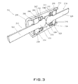
- FIG. 3 is a perspective cross-sectional view of an illustrative rod system of FIG. 2 ;
- FIG. 4 is a partial side cross-sectional view of an illustrative rod system of FIG. 2 ;
- FIG. 5 is an exploded view of an illustrative rod system of FIG. 2 ;
- FIG. 6 is a front view of an illustrative translation and rotation of the rod system of FIG. 2 , all arranged in accordance with at least some embodiments described herein.
- This disclosure is drawn, inter alia, to manufacturing methods, apparatus, systems, and techniques related to a dynamic rod system for a bone fixation system.
- Bone screws are used in spinal instrumentation to manage bone fractures and correct deformity.
- pedicle screws may provide a means of gripping a spinal segment, where a screw acts as a firm anchor point in one vertebra that can be connected to other such anchor points in other vertebrae with a rod. With two or more consecutive vertebrae fixated by such a construct, motion between the vertebrae is prevented or limited.
- a rod system in one or more embodiments of the present disclosure, includes two rods held against each other by elastic members within a cylindrical case. Each rod is initially immobilized by a corresponding stopper made of an absorbable material so the rod system is rigid. The two rods are connected to two bone screws attached to two vertebrae. As the absorbable material is decomposed by bodily fluid introduced through holes in the cylindrical case, the corresponding rod gains mobility and the rod system becomes dynamic.
- FIG. 1 is a perspective view of an illustrative bone fixation system 100 attached to vertebrae in one or more embodiments of the present disclosure.
- the bone fixation system 100 includes a first bone screw 102 attached on a first bone 104 , a second bone screw 106 attached on a second bone 108 , and a rod system 110 connected at two ends to the bone screws 102 and 106 .
- the rod system 110 may initially form a rigid link between the bone screws 102 and 106 and then transition over time to a dynamic link between the bone screws 102 and 106 .
- the bone screws 102 and 106 may be pedicle screws, and bones 104 and 108 may be vertebrae. The configuration is mirrored on both sides of the vertebrae.
- FIG. 2 is a perspective view of an illustrative rod system 110 of the bone fixation system 100 in FIG. 1 .
- the rod system 110 includes a first rod 202 and a second rod 204 extending from two ends of a cylindrical case 206 .
- the first rod 202 is connected to the first bone screw 102 of FIG. 1 and the second rod 204 is connected to the second bone screw 106 of FIG. 1 .
- the cylindrical case 206 defines two sets of through holes 208 around the circumference for introducing bodily fluid into the cylindrical case 206 .
- FIGS. 3 , 4 , and 5 show perspective cross-sectional view, a partial side cross-sectional view, and an exploded view of the rod system 110 in one or more embodiments of the present disclosure.
- the bone fixation system 110 includes the first rod 202 , the second rod 204 , first elastic members 302 , second elastic members 304 , a first retainer ring 306 , a second retainer ring 308 , a third retainer ring 310 , a fourth retainer ring 312 , a first stopper ring 314 , a second stopper ring 316 , a third stopper ring 307 , a fourth stopper ring 311 , and the cylindrical case 206 .
- the first rod 202 , the second rod 204 , the first retainer ring 306 , the second retainer ring 308 , the third retainer ring 310 , the fourth retainer ring 312 , the third stopper ring 307 , the fourth stopper ring 311 , and the cylindrical case 206 may be made from metal that resist biological corrosions, such as titanium alloy and stainless steel.
- the cylindrical case 206 includes two symmetrical halves 401 each defining a first counterbore 402 at one end for receiving the first rod 202 , a second counterbore 404 at the other end for receiving the second rod 204 , and a mid-bore 406 in communication with the counterbores 402 and 404 .
- the first counterbore 402 includes an inner circumferential cutout 408 for receiving the first retainer ring 306 , and an outer circumferential cutout 410 for receiving the second retainer ring 308 .
- the second counterbore 404 includes an inner circumferential cutout 412 for receiving the third retainer ring 310 , and an outer circumferential cutout 414 for receiving the fourth retainer ring 312 .
- the first rod 202 includes a hemispheroid head 318 , a neck 320 extending from the head 318 , and a shaft 322 extending from the neck 320 .
- the neck 320 has a smaller radius than the head 318
- the shaft 322 has a smaller radius than the neck 320 .
- first elastic members 302 and the second elastic members 304 may each include one or more elastic washers.
- the first elastic members 302 have an outer radius substantially the same as the radius of the first counterbore 402 , and defines a hole having a radius substantially equal to the radius of the neck 320 .
- the third stopper ring 307 has an outer radius substantially the same as the radius of the first counterbore 402 , and an inner radius substantially equal to the radius of the neck 320 .
- the third stopper ring 307 is configured to be a stopping base of the first elastic members 302 and to limit the motion of the second rod 204 .
- the first retainer ring 306 has an outer radius substantially the same as the radius of the inner circumferential cutout 408 , and an inner radius larger than the radius of the neck 320 .
- the first stopper ring 314 has an inner ring portion and an outer ring portion.
- the inner ring portion has an outer radius substantially equal to the inner radius of the first retainer ring 306 , and an inner radius substantially equal to the radius of the neck 320 .
- the outer ring portion has an outer radius substantially equal to the radius of the first counterbore 402 , and an inner radius substantially equal to the radius of the shaft 322 .
- the first stopper ring 314 can be made of an absorbable material that is decomposed by bodily fluid, such as calcium phosphate and calcium sulphate.
- the second retainer ring 308 has an outer radius substantially the same as the radius of the outer circumferential cutout 410 , and an inner radius larger than the radius of the shaft 322 .
- the first rod 202 is inserted through the first elastic members 302 , the third stopper ring 307 , the first retainer ring 306 , the first stopper ring 314 , and the second retainer ring 308 .
- the first elastic members 302 abut against the bottom of the head 318 .
- the first retainer ring 306 fits around the inner ring portion of the first stopper ring 314 , and both abut against the bottom of the first elastic members 302 .
- the second retainer ring 308 abuts the bottom of the first stopper ring 314 .
- the assembly is placed in one half 401 of the cylindrical case 206 so the head 318 protrudes into the mid-bore 406 .
- the first elastic members 302 abut the bottom of the first counterbore 402 .
- the first retainer ring 306 fits in the inner circumferential cutout 408
- the second retainer ring 308 fits in the outer circumferential cutout 410 .
- one set of through holes 208 are defined in the cylindrical case 206 around the first stopper ring 314 .
- the second rod 204 includes a hemispheroid head 324 , a neck 326 extending from the head 324 , and a shaft 328 extending from the neck 326 .
- the neck 326 has a smaller radius than the head 324
- the shaft 328 has a smaller radius than the neck 326 .
- the second elastic members 304 have an outer radius substantially the same as the radius of the second counterbore 404 , and defines a hob having a radius substantially equal to the radius of the neck 326 .
- the fourth stopper ring 311 has an outer radius substantially the same as the radius of the second counterbore 404 , and an inner radius substantially equal to the radius of the neck 326 .
- the fourth stopper ring 311 is configured to be a stopping base of the second elastic members 304 and to limit the motion of the first rod 202 .
- the third retainer ring 310 has an outer radius substantially the same as the radius of the inner circumferential cutout 412 , and an inner radius larger than the radius of the neck 326 .
- the second stopper ring 316 has an inner ring portion and an outer ring portion.
- the inner ring portion has an outer radius substantially equal to the inner radius of the third retainer ring 310 , and an inner radius substantially equal to the radius of the neck 326 .
- the outer ring portion has an outer radius substantially equal to the radius of the second counterbore 404 , and an inner radius substantially equal to the radius of the shaft 328 .
- the second stopper ring 316 is made of an absorbable material that is decomposed by bodily fluid, such as calcium phosphate and calcium sulphate.
- the fourth retainer ring 312 has an outer radius substantially the same as the radius of the outer circumferential cutout 414 , and an inner radius larger than the radius of the shaft 328 .
- the second rod 204 is inserted through the second elastic members 304 , the fourth stopper ring 311 , the third retainer ring 310 , the second stopper ring 316 , and the fourth retainer ring 312 .
- the second elastic members 304 abut against the bottom of the head 324 .
- the third retainer ring 310 fits around the inner ring portion of the second stopper ring 316 , and both abut against the bottom of the second elastic members 304 .
- the fourth retainer ring 312 abuts the bottom of the second stopper ring 316 .
- This assembly is placed in one half 401 of the cylindrical case 206 so the head 324 protrudes into the mid-bore 406 and abuts the head 318 , the second elastic members 304 abut the bottom of the second counterbore 404 , the third retainer ring 310 fits in the inner circumferential cutout 412 , and the fourth retainer ring 312 fits in the outer circumferential cutout 414 .
- another set of through holes 208 are defined in the cylindrical case 206 around the second stopper ring 316 .
- the two halves 401 are then fixed by welding or other methods.
- the first stopper ring 314 is fixed by the first retainer ring 306 and the second retainer ring 308 . In turn, the first stopper ring 314 prevents the first rod 202 from translating outward and rotating.
- the second stopper ring 316 is fixed by the third retainer ring 310 and the fourth retainer ring 312 . In turn, the second stopper ring 316 prevents the second rod 204 from translating outward and rotating. As the first rod 202 and the second rod 204 abut each other, they prevent each other from translating inward as well.
- bodily fluid enters through holes 208 and decomposes the first stopper ring 314 and the second stopper ring 316 .
- the first rod With the first stopper ring 314 removed, the first rod is able to translate outward and rotate against the first elastic members 302 .
- the second stopper ring 316 With the second stopper ring 316 removed, the second rod 204 is able to translate outward and rotate against the second elastic members 304 .
- rod system 110 may be constructed without the stopper rings 314 and 316 .
- the two rods can translate outward independently of each other.
- One rod can also translate inward and push the other rod outward.
- the two rods can always rotate independently as they contact through their hemispheroid head 318 and 324 . Together they allow the rod system 110 to provide six degrees-of-freedom.
- each rod may have an axial translation of about ⁇ 0.1 to 0.3 mm, such as ⁇ 0.2 mm, along each rod axis.
- the inner radii of retainer rings 308 and 312 are selected to larger than the radii of the shafts 322 and 328 provide a predetermined limit for frontal and the sagittal rotations of the first rod 202 and the second rod 204 .
- each rod may have frontal and sagittal rotations of about ⁇ 1 to 3°, such as ⁇ 2°.
- FIG. 6 shows a front view of an illustrative translation and rotation of the rod system 110 of FIG. 2 .
Landscapes
- Health & Medical Sciences (AREA)
- Orthopedic Medicine & Surgery (AREA)
- Life Sciences & Earth Sciences (AREA)
- Neurology (AREA)
- Surgery (AREA)
- Heart & Thoracic Surgery (AREA)
- Engineering & Computer Science (AREA)
- Biomedical Technology (AREA)
- Nuclear Medicine, Radiotherapy & Molecular Imaging (AREA)
- Medical Informatics (AREA)
- Molecular Biology (AREA)
- Animal Behavior & Ethology (AREA)
- General Health & Medical Sciences (AREA)
- Public Health (AREA)
- Veterinary Medicine (AREA)
- Prostheses (AREA)
- Surgical Instruments (AREA)
Applications Claiming Priority (1)
| Application Number | Priority Date | Filing Date | Title |
|---|---|---|---|
| PCT/CN2010/076195 WO2012022047A1 (fr) | 2010-08-20 | 2010-08-20 | Système de tige pour fixation spinale dynamique progressive |
Related Parent Applications (1)
| Application Number | Title | Priority Date | Filing Date |
|---|---|---|---|
| PCT/CN2010/076195 A-371-Of-International WO2012022047A1 (fr) | 2010-08-20 | 2010-08-20 | Système de tige pour fixation spinale dynamique progressive |
Related Child Applications (1)
| Application Number | Title | Priority Date | Filing Date |
|---|---|---|---|
| US14/208,877 Continuation US8992577B2 (en) | 2010-08-20 | 2014-03-13 | Rod system for gradual dynamic spinal fixation |
Publications (2)
| Publication Number | Publication Date |
|---|---|
| US20130261667A1 US20130261667A1 (en) | 2013-10-03 |
| US8709048B2 true US8709048B2 (en) | 2014-04-29 |
Family
ID=45604700
Family Applications (2)
| Application Number | Title | Priority Date | Filing Date |
|---|---|---|---|
| US13/376,502 Expired - Fee Related US8709048B2 (en) | 2010-08-20 | 2010-08-20 | Rod system for gradual dynamic spinal fixation |
| US14/208,877 Expired - Fee Related US8992577B2 (en) | 2010-08-20 | 2014-03-13 | Rod system for gradual dynamic spinal fixation |
Family Applications After (1)
| Application Number | Title | Priority Date | Filing Date |
|---|---|---|---|
| US14/208,877 Expired - Fee Related US8992577B2 (en) | 2010-08-20 | 2014-03-13 | Rod system for gradual dynamic spinal fixation |
Country Status (2)
| Country | Link |
|---|---|
| US (2) | US8709048B2 (fr) |
| WO (1) | WO2012022047A1 (fr) |
Cited By (2)
| Publication number | Priority date | Publication date | Assignee | Title |
|---|---|---|---|---|
| US8992577B2 (en) | 2010-08-20 | 2015-03-31 | Tongji University | Rod system for gradual dynamic spinal fixation |
| US11583318B2 (en) | 2018-12-21 | 2023-02-21 | Paradigm Spine, Llc | Modular spine stabilization system and associated instruments |
Families Citing this family (2)
| Publication number | Priority date | Publication date | Assignee | Title |
|---|---|---|---|---|
| US10053456B2 (en) * | 2014-04-11 | 2018-08-21 | Takeda Pharmaceutical Company Limited | Cyclopropanamine compound and use thereof |
| US10004538B2 (en) * | 2016-04-27 | 2018-06-26 | Warsaw Orthopedic, Inc. | Surgical instrument and method |
Citations (13)
| Publication number | Priority date | Publication date | Assignee | Title |
|---|---|---|---|---|
| JP2002224131A (ja) | 2001-02-05 | 2002-08-13 | Mizuho Co Ltd | 椎間固定装置 |
| FR2827498A1 (fr) | 2001-07-18 | 2003-01-24 | Frederic Fortin | Dispositif de liaison vertebrale souple constitue d'elements palliant une deficience du rachis |
| CN1463678A (zh) | 2002-06-17 | 2003-12-31 | 颜宗宝 | 骨科用滑杆外固定装置 |
| US20070233073A1 (en) | 2006-03-02 | 2007-10-04 | Sdgi Holdings, Inc. | Spinal rod characterized by a time-varying stiffness |
| US20080015578A1 (en) | 2006-07-12 | 2008-01-17 | Dave Erickson | Orthopedic implants comprising bioabsorbable metal |
| US7326210B2 (en) | 2003-09-24 | 2008-02-05 | N Spine, Inc | Spinal stabilization device |
| US20080262554A1 (en) * | 2004-10-20 | 2008-10-23 | Stanley Kyle Hayes | Dyanamic rod |
| FR2931354A1 (fr) | 2008-05-23 | 2009-11-27 | Biospine Implants | Dispositif de stabilisation posterieur dynamique epousant la lordose anatomique |
| US20100036423A1 (en) | 2004-10-20 | 2010-02-11 | Stanley Kyle Hayes | Dynamic rod |
| US7686833B1 (en) | 2004-04-02 | 2010-03-30 | Muhanna Nabil L | Ball jointed pedicle screw and rod system |
| US20100094424A1 (en) * | 2007-03-13 | 2010-04-15 | William Woodburn | Adjustable intervertebral implant |
| US20100114167A1 (en) | 2008-10-31 | 2010-05-06 | Warsaw Orthopedic, Inc. | Transition rod |
| US8287571B2 (en) * | 2008-08-12 | 2012-10-16 | Blackstone Medical, Inc. | Apparatus for stabilizing vertebral bodies |
Family Cites Families (1)
| Publication number | Priority date | Publication date | Assignee | Title |
|---|---|---|---|---|
| US8709048B2 (en) | 2010-08-20 | 2014-04-29 | Tongji University | Rod system for gradual dynamic spinal fixation |
-
2010
- 2010-08-20 US US13/376,502 patent/US8709048B2/en not_active Expired - Fee Related
- 2010-08-20 WO PCT/CN2010/076195 patent/WO2012022047A1/fr active Application Filing
-
2014
- 2014-03-13 US US14/208,877 patent/US8992577B2/en not_active Expired - Fee Related
Patent Citations (24)
| Publication number | Priority date | Publication date | Assignee | Title |
|---|---|---|---|---|
| JP2002224131A (ja) | 2001-02-05 | 2002-08-13 | Mizuho Co Ltd | 椎間固定装置 |
| US7776071B2 (en) | 2001-07-18 | 2010-08-17 | Paradigm Spine, Llc | Flexible vertebral linking device |
| WO2003007828A1 (fr) | 2001-07-18 | 2003-01-30 | Frederic Fortin | Dispositif de liaison vertebrale souple |
| EP1408860A1 (fr) | 2001-07-18 | 2004-04-21 | Fortin, Frédéric | Dispositif de liaison vertebrale souple |
| JP2005504566A (ja) | 2001-07-18 | 2005-02-17 | フレデリック フォルタン, | 柔軟脊髄連結装置 |
| US20050165396A1 (en) | 2001-07-18 | 2005-07-28 | Frederic Fortin | Flexible vertebral linking device |
| US20050261685A1 (en) | 2001-07-18 | 2005-11-24 | Frederic Fortin | Flexible vertebral linking device |
| US7763048B2 (en) | 2001-07-18 | 2010-07-27 | Fourth Dimension Spine, LLC | Flexible vertebral linking device |
| FR2827498A1 (fr) | 2001-07-18 | 2003-01-24 | Frederic Fortin | Dispositif de liaison vertebrale souple constitue d'elements palliant une deficience du rachis |
| CN1463678A (zh) | 2002-06-17 | 2003-12-31 | 颜宗宝 | 骨科用滑杆外固定装置 |
| CN1286435C (zh) | 2002-06-17 | 2006-11-29 | 颜宗宝 | 骨科用滑杆外固定装置 |
| US7326210B2 (en) | 2003-09-24 | 2008-02-05 | N Spine, Inc | Spinal stabilization device |
| US7686833B1 (en) | 2004-04-02 | 2010-03-30 | Muhanna Nabil L | Ball jointed pedicle screw and rod system |
| US20080262554A1 (en) * | 2004-10-20 | 2008-10-23 | Stanley Kyle Hayes | Dyanamic rod |
| US20100036423A1 (en) | 2004-10-20 | 2010-02-11 | Stanley Kyle Hayes | Dynamic rod |
| US20070233073A1 (en) | 2006-03-02 | 2007-10-04 | Sdgi Holdings, Inc. | Spinal rod characterized by a time-varying stiffness |
| US20080015578A1 (en) | 2006-07-12 | 2008-01-17 | Dave Erickson | Orthopedic implants comprising bioabsorbable metal |
| US20100094424A1 (en) * | 2007-03-13 | 2010-04-15 | William Woodburn | Adjustable intervertebral implant |
| WO2009153431A1 (fr) | 2008-05-23 | 2009-12-23 | Biospine Implants | Dispositif de stabilisation posterieur dynamique epousant la lordose anatomique |
| FR2931354A1 (fr) | 2008-05-23 | 2009-11-27 | Biospine Implants | Dispositif de stabilisation posterieur dynamique epousant la lordose anatomique |
| FR2931354B1 (fr) | 2008-05-23 | 2010-05-14 | Biospine Implants | Dispositif de stabilisation posterieur dynamique epousant la lordose anatomique |
| US8287571B2 (en) * | 2008-08-12 | 2012-10-16 | Blackstone Medical, Inc. | Apparatus for stabilizing vertebral bodies |
| WO2010019791A2 (fr) | 2008-08-14 | 2010-02-18 | Vertiflex, Inc. | Tige dynamique |
| US20100114167A1 (en) | 2008-10-31 | 2010-05-06 | Warsaw Orthopedic, Inc. | Transition rod |
Non-Patent Citations (9)
| Title |
|---|
| G. Perrin, A. Cristini. Prevention of adjacent level degeneration above a fused vertebral segment: Long term effect, after a mean follow-up of 8.27 years, of the dynamic intervertebral fixation as a protective technique for pathological adjacent disc. IMAST 2003. |
| PCT Search Report and Written Opinion dated Jun. 2, 2011 in Application No. PCT/CN2010/076195. |
| Schmoelz W, Huber JF, Nydegger T, et al. Dynamic stabilization of the lumbar spine and its effects on adjacent segments: an in vitro experiment. J Spinal Disord Tech, 2003;16:418-23. |
| Self-design and Preliminary Application of Zygapophyseal Joint System in Patients with Lumbar Distability. 2007;11(4):254-259. (Original Chinese Article with English Abstract). |
| Sengupta DK, Mulholland RC. Fulcrum assisted soft stabilization system: a new concept in the surgical treatment of degenerative low back pain. Spine,2005;30(9):1019-1029. |
| Website-Scient'x Alphatec Spine-Thoraco-Lumbar Fixation, http://www.scientx.com/product-thoracolumbarfixation-ttldynamicrod.php#, printed on Oct. 21, 2011. |
| Website—Scient'x Alphatec Spine—Thoraco-Lumbar Fixation, http://www.scientx.com/product—thoracolumbarfixation—ttldynamicrod.php#, printed on Oct. 21, 2011. |
| Wilke HJ, Schmidt H, Werner K, et al. Biomechanical evaluation of a new total posterior-element replacement system. Spine,2006;31(24):2790-6. |
| Zhu Q, Larson CR, Sjovold SG, et al. Biomechanical evaluation of the Total Facet Arthroplasty System: 3-dimensional kinematics. Spine, 2007,32(1):55-62. |
Cited By (2)
| Publication number | Priority date | Publication date | Assignee | Title |
|---|---|---|---|---|
| US8992577B2 (en) | 2010-08-20 | 2015-03-31 | Tongji University | Rod system for gradual dynamic spinal fixation |
| US11583318B2 (en) | 2018-12-21 | 2023-02-21 | Paradigm Spine, Llc | Modular spine stabilization system and associated instruments |
Also Published As
| Publication number | Publication date |
|---|---|
| US20130261667A1 (en) | 2013-10-03 |
| US20140194931A1 (en) | 2014-07-10 |
| US8992577B2 (en) | 2015-03-31 |
| WO2012022047A1 (fr) | 2012-02-23 |
Similar Documents
| Publication | Publication Date | Title |
|---|---|---|
| JP6076948B2 (ja) | 椎体を安定させるための装置 | |
| US8992577B2 (en) | Rod system for gradual dynamic spinal fixation | |
| AU2004266737B2 (en) | Multi-axial orthopedic device and system, e.g. for spinal surgery | |
| US9993270B2 (en) | Bone fastener and methods of use | |
| US9050153B2 (en) | Universally deployable and expandable bone screw anchor | |
| US11839410B2 (en) | Magnetic implants with improved anatomical compatibility | |
| EP3442452B1 (fr) | Dispositifs d'arthrodèse pour produire et appliquer une compression dans des articulations | |
| KR20100014881A (ko) | 뼈 고정 요소 | |
| US20090069849A1 (en) | Dynamic screw system | |
| JP2004148126A (ja) | ユニバーサル型多軸式ワッシャー組立体 | |
| US20130211467A1 (en) | Connector and fastener system | |
| US20080147124A1 (en) | Bone plate system with slidable compression holes | |
| JP2014517739A (ja) | 拡張式脊椎アンカー | |
| KR20120099634A (ko) | 조직을 이동시키기 위한 체내 장치 | |
| MX2010010362A (es) | Barras estabilizadoras. | |
| US20160166291A1 (en) | Bioactive Fusion Device | |
| US20210353333A1 (en) | Integral double rod spinal construct | |
| US20170105766A1 (en) | Polyaxial Bone Screw and Bushing | |
| Bonnaire et al. | Reduced complication rates for unstable trochanteric fractures managed with third-generation nails: Gamma 3 nail versus PFNA | |
| US20090228044A1 (en) | Systems and methods for mobile spinal fixation rods | |
| RU2606269C2 (ru) | Комплект для репозиции и наружной фиксации отломков костей конечностей и/или таза | |
| Asher et al. | Analysis of instrumentation/fusion survivorship without reoperation after primary posterior multiple anchor instrumentation and arthrodesis for idiopathic scoliosis | |
| Niwa et al. | Use of a fenestrated aneurysm clip for transposition of the tortuous vertebral artery | |
| Maai et al. | Intramedullary limb lengthening: comparative mechanical testing of different devices | |
| JP7223459B1 (ja) | 骨粗鬆症のある頚椎の前方固定システム |
Legal Events
| Date | Code | Title | Description |
|---|---|---|---|
| AS | Assignment |
Owner name: TONGJI UNIVERSITY, CHINA Free format text: ASSIGNMENT OF ASSIGNORS INTEREST;ASSIGNORS:CHENG, LIMING;YU, YAN;ZENG, ZHILI;AND OTHERS;REEL/FRAME:027496/0063 Effective date: 20101118 Owner name: TONGJI UNIVERSITY, CHINA Free format text: ASSIGNMENT OF ASSIGNORS INTEREST;ASSIGNORS:CHENG, LIMING;YU, YAN;ZENG, ZHILI;AND OTHERS;REEL/FRAME:027496/0318 Effective date: 20101118 |
|
| STCF | Information on status: patent grant |
Free format text: PATENTED CASE |
|
| CC | Certificate of correction | ||
| MAFP | Maintenance fee payment |
Free format text: PAYMENT OF MAINTENANCE FEE, 4TH YEAR, LARGE ENTITY (ORIGINAL EVENT CODE: M1551) Year of fee payment: 4 |
|
| AS | Assignment |
Owner name: CRESTLINE DIRECT FINANCE, L.P., TEXAS Free format text: SECURITY INTEREST;ASSIGNOR:EMPIRE TECHNOLOGY DEVELOPMENT LLC;REEL/FRAME:048373/0217 Effective date: 20181228 |
|
| AS | Assignment |
Owner name: EMPIRE TECHNOLOGY DEVELOPMENT LLC, WASHINGTON Free format text: RELEASE BY SECURED PARTY;ASSIGNOR:CRESTLINE DIRECT FINANCE, L.P.;REEL/FRAME:049924/0794 Effective date: 20190501 |
|
| FEPP | Fee payment procedure |
Free format text: MAINTENANCE FEE REMINDER MAILED (ORIGINAL EVENT CODE: REM.); ENTITY STATUS OF PATENT OWNER: LARGE ENTITY |
|
| LAPS | Lapse for failure to pay maintenance fees |
Free format text: PATENT EXPIRED FOR FAILURE TO PAY MAINTENANCE FEES (ORIGINAL EVENT CODE: EXP.); ENTITY STATUS OF PATENT OWNER: LARGE ENTITY |
|
| STCH | Information on status: patent discontinuation |
Free format text: PATENT EXPIRED DUE TO NONPAYMENT OF MAINTENANCE FEES UNDER 37 CFR 1.362 |
|
| FP | Lapsed due to failure to pay maintenance fee |
Effective date: 20220429 |