US8708849B2 - Inverted tooth chain sprocket with frequency modulated meshing features - Google Patents
Inverted tooth chain sprocket with frequency modulated meshing features Download PDFInfo
- Publication number
- US8708849B2 US8708849B2 US13/081,283 US201113081283A US8708849B2 US 8708849 B2 US8708849 B2 US 8708849B2 US 201113081283 A US201113081283 A US 201113081283A US 8708849 B2 US8708849 B2 US 8708849B2
- Authority
- US
- United States
- Prior art keywords
- flank
- tooth
- sprocket
- teeth
- relieved
- Prior art date
- Legal status (The legal status is an assumption and is not a legal conclusion. Google has not performed a legal analysis and makes no representation as to the accuracy of the status listed.)
- Expired - Fee Related, expires
Links
Images


Classifications
-
- F—MECHANICAL ENGINEERING; LIGHTING; HEATING; WEAPONS; BLASTING
- F16—ENGINEERING ELEMENTS AND UNITS; GENERAL MEASURES FOR PRODUCING AND MAINTAINING EFFECTIVE FUNCTIONING OF MACHINES OR INSTALLATIONS; THERMAL INSULATION IN GENERAL
- F16H—GEARING
- F16H7/00—Gearings for conveying rotary motion by endless flexible members
- F16H7/06—Gearings for conveying rotary motion by endless flexible members with chains
-
- F—MECHANICAL ENGINEERING; LIGHTING; HEATING; WEAPONS; BLASTING
- F16—ENGINEERING ELEMENTS AND UNITS; GENERAL MEASURES FOR PRODUCING AND MAINTAINING EFFECTIVE FUNCTIONING OF MACHINES OR INSTALLATIONS; THERMAL INSULATION IN GENERAL
- F16H—GEARING
- F16H55/00—Elements with teeth or friction surfaces for conveying motion; Worms, pulleys or sheaves for gearing mechanisms
- F16H55/02—Toothed members; Worms
- F16H55/30—Chain-wheels
Definitions
- the initial inside flank chain-sprocket meshing impact is the major noise contributor during the meshing phenomena with the secondary meshing impact during the transition to outside flank meshing also contributing to the overall noise level, albeit to a lesser degree.
- the meshing impacts are repeated with a frequency generally equal to that of the frequency of the chain meshing with the sprocket. It is known that chain drive noise levels can be effectively reduced by modulating the meshing frequency and this can be achieved in various ways—but always by altering the rhythm of the chain-sprocket meshing impacts.
- a sprocket in accordance with one exemplary embodiment, includes a body comprising a plurality of teeth defined relative to a respective tooth centers. The tooth centers are spaced evenly in a circumferential arrangement.
- Each of the plurality of teeth includes an engaging flank and a disengaging flank.
- Each pair of circumferentially successive teeth of said plurality of teeth are separated from each other by respective tooth spaces, and each of the tooth spaces is defined at least partially by the engaging flank of one of said circumferentially successive teeth, the disengaging flank of the other of said circumferentially successive teeth, and a root surface that is located between the engaging flank and the disengaging flank of the tooth space.
- the engaging flank of each tooth space is defined as a mirror image of the disengaging flank of each tooth space relative to a tooth space centerline that bisects said tooth space such that each tooth space is symmetrically defined about its tooth space centerline.
- the plurality of teeth comprise Type A Standard Teeth, Type B Standard Teeth, Type A Relieved Teeth, and Type B Relieved Teeth, wherein:
- an inverted tooth chain drive system includes a sprocket adapted to mesh with an associated inside flank engagement inverted tooth chain.
- the sprocket includes a plurality of teeth defined relative to respective tooth centers. The tooth centers are spaced evenly in a circumferential arrangement about the axis of rotation, each tooth comprising an engaging flank and a disengaging flank.
- An inverted tooth chain is engaged with the sprocket and includes a plurality of rows of links each structured for inside flank engagement with the sprocket, with leading inside flanks of each row of links projecting outwardly relative to the trailing outside flanks of a preceding row of links.
- each row is positioned to make initial meshing contact with the engaging flank of one of the sprocket teeth.
- At least some of the sprocket teeth are standard teeth and other teeth are flank-relieved teeth, and it is the engaging flank that defines whether a tooth is standard or flank-relieved (i.e., a tooth is deemed to be a standard tooth if its engaging flank is standard (not relieved), and a tooth is deemed to be a flank-relieved tooth if its engaging flank is relieved as compared to a standard engaging flank).
- the engaging flank of a first tooth and the disengaging flank of a second adjacent tooth sharing the same tooth space are flank-relieved and the disengaging flank of the second tooth is a mirror image of the engaging flank of the first tooth.
- the engaging flanks of the flank-relieved teeth are negatively offset relative to their respective tooth centers as compared to the engaging flanks of the standard teeth relative to their respective tooth centers.
- the root surface located forward of a flank-relieved tooth is raised (located radially outward) relative to the root surface forward of a standard tooth.
- flank-relieved teeth will be incorporated into the full complement of sprocket teeth of the sprocket in random (irregular) or fixed patterns, including repeating patterns, in order to stagger or modulate the meshing impacts between the chain and sprocket teeth.
- Each tooth space of the sprocket that is partially defined by a flank-relieved engaging flank is symmetrically defined about a tooth space centerline which permits the sprocket to be bi-directional, i.e., when rotated in either direction, a desired frequency modulation of the meshing impacts will function in substantially the same manner.
- a preferred minimum and maximum flank offset range is defined.
- the smallest flank-relief offset will be of a magnitude to modulate the initial meshing impacts by 0.5 degrees of sprocket rotation, and the maximum flank-relief offset will be determined as a function of limiting the chordal motion at initial meshing contact as measured from the tangent line, with the limiting value for actual chordal motion to be defined as 0.75 CM THEOR where CM THEOR is the maximum theoretical chordal motion.
- flank-relieved teeth will not all have the same amount of offset.
- flank-relieved teeth may have a pressure angle that is different than the pressure angle of the conventional teeth that do not have flank-relief.
- FIG. 1 is a partial front elevational view of a chain drive system comprising a conventional inverted tooth chain (with some guide links removed for clarity) meshing with a sprocket formed in accordance with the present invention
- FIG. 1A is a partial enlarged view of the inverted tooth chain of FIG. 1 to illustrate the meshing geometry at the instant of initial meshing contact with the engaging flank of a conventional sprocket tooth;
- FIG. 1B is a view similar to FIG. 1A but with the sprocket rotated to a new position where the meshing chain link row is making inside flank contact and the preceding row of the chain is simultaneously making outside flank contact with the engaging flank of the first tooth, with a link plate in the foreground removed for clarity in order to more clearly show the simultaneous meshing contacts;
- FIG. 2A is a greatly enlarged illustration of first and second rows of inside link plates of the inverted tooth chain shown in FIG. 1 ;
- FIG. 2B is a plan view of the inverted tooth chain of FIG. 1 ;
- FIGS. 3A and 3B illustrate the chordal rise for a sprocket
- FIG. 4 is a front elevational view of the sprocket of FIG. 1 in its entirety, to illustrate a three-tooth repeating pattern
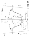
- FIG. 4A is a greatly enlarged view of a flank-relieved tooth of the sprocket shown in FIG. 4 , with the profile of adjacent conventional teeth shown as an overlay in phantom;
- FIG. 5A is a partial enlarged view of the chain drive system of FIG. 1 showing the inverted tooth chain at the instant of initial meshing contact with the engaging flank of a conventional sprocket tooth T 2 ;
- FIG. 5B is a partial front elevational view of the chain drive system of FIG. 5A with the sprocket rotated to a new position where the meshing chain link row is making inside flank contact and the preceding row of the chain is simultaneously making outside flank contact with the engaging flank of the tooth T 2 ;
- FIG. 6A is similar to FIG. 5A and shows the same sprocket and chain system, but shows the chain at the instant of initial meshing contact with a tooth T 1 of the sprocket that is flank-relieved in accordance with the present invention
- FIG. 6B is similar to FIG. 5B but shows the system of FIG. 6A with the sprocket rotated to a new position where the meshing chain link row is making inside flank contact with the tooth T 1 and the preceding row of the chain is simultaneously making root contact with the tooth space root surface forward of the tooth T 1 ;
- FIG. 6C is an enlarged partial front elevational view of FIG. 6B to illustrate the meshing relationship of the leading chain link toe with the sprocket tooth space root surface as the link row rotates into full engagement with the sprocket;
- FIG. 6D is a greatly enlarged partial view of FIG. 6C showing the trailing flank link plate clearance to the engaging flank of the tooth T 1 and the geometrical relationship of the root surface to the chain link toe at full meshing contact;
- FIG. 7 is a front elevational view of a complete sprocket, in its entirety, formed in accordance with another embodiment
- FIG. 8 is a greatly enlarged view of adjacent conventional teeth of the sprocket shown in FIG. 4 with the profile of adjacent conventional teeth formed with a reduced pressure angle shown as an overlay in phantom;
- FIG. 8A is a greatly enlarged view of a flank-relieved tooth of the sprocket shown in FIG. 7 , with the profile of adjacent conventional teeth used to construct the flank-relieved tooth shown as an overlay in phantom;
- FIG. 9 graphically illustrates the meshing dynamics of FIGS. 5A , 5 B, 6 A, 6 B in terms of meshing impacts and chordal motion of the meshing chain link row versus sprocket angular rotation.
- FIG. 1 shows an inverted tooth chain drive system 100 formed in accordance with the present development.
- the system 100 includes a conventional inside flank engagement style inverted tooth chain 10 meshed with a drive sprocket 150 and at least one other sprocket not shown.
- the sprocket rotates about an axis of rotation X, clockwise in the illustrated example.
- the sprocket 150 is formed in accordance with the present invention with tooth flanks having an involute form but the flanks may include a radial form instead of an involute form and/or can comprise or be defined by one or more flats without departing from the overall scope and intent of the present invention.
- the sprocket 150 includes a plurality of teeth T (T 1 , T 2 , T 3 , etc.) each having an engaging flank (E or E′) and a disengaging flank (DE or DE′) located on opposites sides of a tooth center TC.
- T teeth
- E or E′ engaging flank
- DE or DE′ disengaging flank
- the tooth center TC bisects the tooth T.
- the tooth T will be asymmetrically defined relative to its tooth center TC.
- the outside diameter OD and a root diameter RD define the outer and inner radial limits of the tooth flanks.
- FIG. 2A illustrates first and second link rows L (in particular rows L 4 ,L 5 ) of the chain 10 (guide links are removed to reveal the underlying inside link plates).
- the conventional inside link plates 30 of each row L have toes 38 which are each defined by inside flanks Fi and outside flanks Fo interconnected by a tip 37 defined by a radius and/or other surface.
- outside flanks Fo are straight-sided and the inside flanks Fi have a convexly arcuate form and are joined by a crotch 34 .
- the inside flanks Fi of each link 30 are defined by a radius R Fi that preferably blends into the tip 37 of the relevant toe 38 and into the crotch 34 at the opposite end.
- FIG. 2A is a plan view of several rows L of the chain 10 and shows a standard chain lacing having rows L 1 , L 2 , L 3 , L 4 , L 5 , etc.
- each pin 40 has a pin center C with successive pin centers indicated as C 1 , C 2 , C 3 , etc. to distinguish them from each other.
- the pin centers C are spaced at chain link pitch interval P and each pin center C is defined by or coincident with an axis about which adjacent link rows L of the chain articulate relative to each other.
- the chain 10 approaches the drive sprocket 150 substantially along the tangent line TL (at the centers C of the chain pins 40 ) in a taut strand and meshing occurs as the chain inside links 30 of rows L collide with an engaging flank E,E′.
- the centers of the pins 40 travel along and define a circular path referred to as the pitch diameter PD.
- FIG. 3A shows the chain pin center C at a first position where it has just meshed with the sprocket and where it is simultaneously aligned with both the tangent line TL and the sprocket pitch diameter PD.
- the tangent line TL is the theoretical straight-line path along which the meshing chain pin centers C approach the sprocket.
- the tangent line TL is located in a horizontal orientation, in which case the tangent line TL is tangent to the pitch diameter PD at the top-dead-center or 12 o'clock position on the pitch diameter PD, i.e., the tangent line TL is tangent to the pitch diameter PD at a location where a chain pin center C is centered on the pitch diameter PD and the same pin center C is also centered on a radial reference line that extends through the sprocket's axis of rotation and that is normal to the tangent line TL (the reference line being vertical when the tangent line is horizontal as shown herein).
- 3B illustrates the location of the same pin center C after the sprocket has rotated through the angle ⁇ /2, where it can be seen that the pin center C is transversely displaced by a distance CR as it continues its travel around the sprocket wrap, and this vertical displacement of the pin center results in a corresponding displacement of the upstream chain span and tangent line TL thereof.
- This transverse displacement of the chain pins C as they move through the chordal rise and fall serves to induce undesired vibration in the unsupported chain span.
- the chordal rise CR is alternatively referred to herein as the theoretical chordal motion CM THEOR .
- a link row L 5 of chain 10 is at the onset of meshing with a sprocket tooth T 5 of the sprocket 150 .
- Successive pin centers C are numbered C 1 , C 2 , C 3 , C 4 , etc. to distinguish them from each other.
- the link row L 5 is shown at the instant of initial meshing contact with a corresponding sprocket tooth T 5 , i.e., at the instant of initial contact between the leading inside flank Fi of the chain link plate 30 and the engaging flank E of the sprocket tooth T 5 at an initial contact location IC on the engaging flank E.
- Tooth T 5 is referred to herein as a standard tooth because its engaging flank E is a standard form (not relieved).
- an initial contact angle Theta ( ⁇ ) is defined between a first radial reference line REF 1 originating at the axis of rotation X of the sprocket 150 and extending normal to the tangent line TL and a second radial reference line TC 5 originating at the axis of rotation X and extending through the tooth center TC of the sprocket tooth T 5 .
- the preceding link row L 6 exits the chain span and enters a “suspended state”, i.e., the link plates 30 of row L 6 are not in direct contact with the sprocket 150 and are thus suspended between the meshing row L 5 and a preceding row L 7 that is in full meshing contact with a preceding sprocket tooth T 6 .
- Link row L 6 will remain in this suspended state until it completes its meshing cycle and transitions into a position where its trailing outside flanks Fo make full meshing contact at location OF with sprocket tooth T 5 (see FIG. 1B ). As shown in FIG.
- the pin center C 6 can be referred to as the “controlling pin center.”
- the controlling pin center C 6 is the closest preceding (downstream) pin center C relative to the leading pin center C 5 of the meshing link row L 5 (the controlling pin center C 6 is also the trailing pin center of the closest (in terms of chain travel direction) fully meshed link row L 7 ). As such, the following relationships are defined:
- chain-sprocket meshing impact results from a velocity difference between the meshing link row L 5 and a sprocket tooth T 5 at the initial contact location IC
- the meshing impacts along with the associated noise levels can be reduced by decreasing the velocity difference, which can be accomplished by reducing the meshing entrance angle ⁇ .
- the impact energy E I equation considers only the mass of the meshing link row L 5 , and it does not take into account chain tension T C and this chain tension will add to the resultant meshing impact energy E I and the associated overall noise levels.
- the chain tension T C will act on the sprocket tooth T 5 at the onset of meshing and the tooth impact reaction force F S , equal and opposite to a link impact force F L , will vary with the magnitude of the meshing impact angle ⁇ , where:
- the link impact force vector F L acts at the meshing impact location IC during initial meshing contact and adds to the total meshing impact energy E I and the related noise levels.
- FIG. 1B is similar to FIG. 1A but shows the sprocket 150 rotated further through the meshing cycle until the instant when the trailing outside flanks Fo of preceding link row L 6 make contact with the engaging flank E of sprocket tooth T 5 at an outside flank contact location OF while the leading inside flanks Fi of link row L 5 are simultaneously contacting the engaging flank E at a location IF.
- transition point the instant at which the tooth T 5 transitions from inside flank only contact with leading inside flanks Fi of link row L 5 also to outside flank contact with trailing outside flanks Fo of preceding link row L 6 at an outside flank contact point OF can be referred to as a “transition point,” and also defines the end of the meshing cycle for the standard tooth T 5 , because the link row L 6 is then fully meshed with both its leading and trailing pin centers C 6 ,C 5 located on the pitch diameter PD such that the link row L 6 is then located in its fully meshed or seated chordal position and is considered to be in the wrap of the sprocket 150 .
- a transition angle Phi ( ⁇ ) is defined between the first radial reference line REF 1 and the second radial reference line TC 5 passing through the tooth center TC of tooth T 5 . As such, the following relationships are defined:
- the resulting link plate transition angle Beta′ ( ⁇ ′) and transition impact angle Sigma′ ( ⁇ ′) will dictate the link impact force F′ L and resultant impact energy E I for the transitional impact of the trailing outside flanks Fo at location OF.
- features in FIG. 1B that correspond to features of FIG. 1A are labeled with corresponding reference characters including a prime (′) designation, and not all are discussed further.
- the transition impact angle Sigma′ ( ⁇ ′) and its constituents are shown relative to a reference line 92 that is parallel to the tangent line TL and extending through the outside flank contact location OF, coincident with the force vector F′ H .
- transitional impacts of the trailing outside flanks Fo at locations OF are thought to be a less significant contributor of noise and vibration as compared to the above described initial meshing impacts of the leading inside flanks Fi at locations IC, but it is believed that controlling the transition impact angle Sigma′ ( ⁇ ′) and its constituents, i.e., the link plate transition angle Beta′ ( ⁇ ′) and the transition contact angle Tau′ ( ⁇ ′), is desirable for further minimizing noise and vibration in the system 100 .
- FIG. 4 is a front elevational view of the sprocket 150 of FIG. 1 in its entirety, to illustrate a three-tooth repeating pattern for teeth T 1 , T 2 , T 3 , which is repeated continuous around the circumference of the sprocket.
- Each pair of circumferentially successive teeth T i.e., T 1 , T 2 , T 3 , etc.
- the disengaging flank DE or DE′ of the preceding sprocket tooth T T 2 in FIG.
- FIG. 4A is shaped as a mirror image of the engaging flank E or E′ of the subject sprocket tooth T relative to the tooth space centerline.
- the phantom lines of FIG. 4A show that if the tooth T 1 is a standard sprocket tooth with a conventional or non-relieved full-material engaging flank E, the preceding tooth T 2 will have a conventional or non-relieved full-material disengaging flank DE, and a standard tooth space 160 is defined about a tooth space centerline TSC that extends through the sprocket axis of rotation X and that bisects the tooth space 160 .
- the standard tooth space 160 includes and is partially defined by a standard root surface R (also shown in phantom lines) that defines the minimum root diameter RD of the sprocket 150 .
- a standard root surface R also shown in phantom lines
- the solid lines of FIG. 4A show that if the tooth T 1 is a flank-relieved sprocket tooth with an engaging flank E′ that is negatively offset or relieved relative to its tooth center TC by an amount FR, the preceding tooth T 2 will likewise have a disengaging flank DE′ that is negatively offset or relieved relative to its tooth center TC by the amount FR, and a relieved tooth space 170 is thus defined about the tooth space centerline TSC.
- the relieved tooth space 170 includes and is partially defined by a raised root surface R′ (also shown in solid lines) that is raised so as to be located radially outward relative to the root surface R of a standard tooth space 160 , and the raised root surface R′ is symmetrically defined about the tooth space centerline TSC for reasons detailed below.
- each tooth space 160 , 170 is defined at least partially by the engaging flank E,E′ of one of said circumferentially successive teeth, the disengaging flank DE,DE′ of the other of said circumferentially successive teeth, and a root surface R,R′ that is located between the engaging flank and the disengaging flank of the tooth space.
- each tooth space 160 , 170 is said to include or comprise the engaging flank E,E′ of a first tooth T 1 , the disengaging flank DE,DE′ of a second tooth T 2 and a root surface R,R′ located between the engaging flank E,E′ of the first tooth T 1 and the disengaging flank DE,DE′ of the second tooth T 2 .
- Circumferentially successive or adjacent teeth defining each tooth space 160 , 170 are sometimes referred to herein as a “pair” of successive or adjacent teeth.
- each tooth T of the sprocket 150 being one of four possible different types:
- the symmetrical relationship of at least the engaging and disengaging flanks E,DE of a standard tooth space 160 , and the symmetrically relationship of the engaging and disengaging flanks E′,DE′ and also the root surface R′ of the relieved tooth space 170 allows the sprocket 150 to be bi-directional such that it will function identically in either direction of rotation and/or with either side facing up/out for a given direction of rotation.
- FIG. 5A is a partial enlarged view of the chain drive system of FIG. 1 showing the inverted tooth chain at the instant of initial meshing contact with the engaging flank of a standard sprocket tooth. It can be seen that an initial contact angle ⁇ 2 is defined with respect to the meshing link row L 2 and the standard tooth T 2 as described above for the angle ⁇ in relation to the meshing link row L 5 and tooth T 5 of FIG. 1A .
- FIG. 5B shows the system of FIG. 5A with the sprocket 150 rotated to the transition point for the meshing link row L 2 and standard tooth T 2 , where the meshing chain link row L 2 is making inside flank contact IF and the preceding row L 3 of the chain is simultaneously making outside flank contact OF with the engaging flank E of the standard tooth T 2 .
- the transition angle ⁇ 2 is defined with respect to the link rows L 2 and L 3 and the tooth T 2 as described above for the angle ⁇ in relation to the link rows L 5 and L 6 and tooth T 5 of FIG. 1B .
- FIG. 6A is similar to FIG. 5A but shows a link row L 1 of the chain 10 at the instant of initial meshing contact with a flank-relieved tooth T 1 .
- An initial contact angle ⁇ 1 is defined with respect to the meshing link row L 1 and the flank-relieved tooth T 1 .
- the initial contact angle ⁇ 2 from FIG. 5A is overlayed on FIG. 6A , and it can be seen that ⁇ 2 > ⁇ 1 by an amount ⁇ .
- the sprocket 150 therefore, must rotate an additional angle ⁇ to establish initial meshing contact IC with flank-relieved tooth T 1 , which, in effect, serves to modulate the meshing frequency with respect to the standard tooth form.
- FIG. 6B is similar to FIG. 5B but shows the sprocket 150 rotated such that the link rows L 1 and L 2 are at the transition point with the flank-relieved tooth T 1 .
- the meshing chain link row L 1 is making inside flank contact IF with the engaging flank E′ and the preceding chain row L 2 has simultaneously articulated into making root contact at location RC with raised root surface R′.
- the transition angle ⁇ 1 is defined with respect to the link rows L 1 and L 2 and the flank-relieved tooth T 1 as described above.
- the transition angle ⁇ 2 from FIG. 5B is overlayed on FIG. 6B and it can be seen that ⁇ 1 > ⁇ 2 by an amount ⁇ .
- the sprocket 150 therefore, must rotate an additional angle ⁇ to reach the transition point for a standard tooth T 2 as compared to a flank-relieved tooth T 1 , which provides further modulation to the system 100 .
- FIG. 6D is a greatly enlarged version of FIG. 6B , with the meshing link row L 1 removed.
- FIG. 6D shows that because the engaging flank E′ is a flank-relieved flank that is negatively offset relative to its tooth center, the trailing outside flanks Fo of the link row L 2 preceding the meshing link row L 1 will never make contact with the engaging flank E′, and a flank clearance FC is defined between the trailing outside flanks Fo of the preceding row L 2 and the engaging flank E′ of the flank-relieved-tooth.
- the trailing toes 37 of its links 30 must make root contact with the sprocket 150 at location RC with the root surface R′, which is the reason that the root surface R′ located adjacent the engaging flank E′ a flank-relived tooth such as tooth T 1 must be raised or located radially outward as compared to the root surface R located adjacent a standard tooth such as tooth T 5 .
- the transition point for a flank-relieved tooth T 1 is thus defined as the first instant when the trailing toes 37 of the preceding link row L 2 make root contact at location RC while the leading inside flanks Fi of the meshing link row L 1 are still in contact with the engaging flank E′ of the tooth T 1 at a location IF, as shown in FIG. 6B .
- the transition angle Phi ⁇ 1 is defined as described above, i.e., between the first radial reference line REF 1 and a second radial reference line TC 1 passing through the tooth center TC of meshing tooth T 1 .
- FIG. 6C is an enlarged partial front elevational view of FIG. 6B to illustrate the meshing relationship of the leading toes 37 of the meshing link row L 1 with the raised root surface R′ as the link row L 1 rotates into full engagement with the sprocket after the trailing toes 37 of the preceding link row L 2 make root contact at location RC with the raised root surface R′.
- the position of the meshing link row L 1 at the transition point is shown in solid lines.
- the relative position of the meshing link row L 1 to the root surface R′ as link row L 1 rotates into full engagement is shown in phantom lines. At the transition point as shown in solid lines in FIG.
- the leading toes 37 of the meshing link row L 1 will be close to the root surface R′ (just to the left of RC in FIG. 6C ) and will sweep on an arc 139 centered at the pin center C 1 and tangent to RC as the sprocket rotates.
- the pin center C 1 is located on the pitch diameter PD due to the root contact at RC made between the trailing toes 37 of preceding link row L 2 and the raised root surface R′. It is important that the leading toes 37 not act as a cam against the root surface R′ as they move relative to the root surface R′, which would undesirably move the pin center C 1 outward relative to the pitch diameter PD.
- the root surface R′ is shaped as a circular arc segment defined by a radius centered at root surface arc center 173 .
- Arc center 173 is located on the tooth space centerline TSC that bisects the tooth space.
- the arc center 173 , pin center C 1 and root contact location RC lie on a straight line (refer also to FIG.
- the root surface R′ is defined symmetrically about the tooth space centerline TSC (and the engaging and disengaging flanks E′, DE′ of the tooth space are symmetrically defined relative to each other).
- FIG. 7 is a front elevational view of a sprocket 250 formed in accordance with another embodiment.
- the sprocket 250 includes tooth spaces 160 defined by successive standard teeth as described above.
- the sprocket 250 also includes tooth spaces 270 that correspond to the tooth spaces 170 described above in that the engaging and disengaging flanks thereof E′′ and DE′′ are flank-relieved.
- the tooth spaces 270 differ from the tooth spaces 170 described above in that the engaging flank E′′ and disengaging flank DE′′ thereof are also defined with a reduced pressure angle as compared to the engaging flank E′ and disengaging flank DE′ of the tooth space 170 .
- Sprocket 250 is also bi-directional, with the engaging flanks E and disengaging flank DE of tooth spaces 160 being mirror images of each other, the engaging flank E′′ and disengaging flank DE′′ of tooth spaces 270 being mirror images of each other, and raised root surfaces R′′ of tooth spaces 270 being symmetrically defined about a tooth space centerline TSC.
- each tooth space 160 , 270 is said to include or comprise the engaging flank E,E′′ of a first tooth T 1 , the disengaging flank DE,DE′′ of a second tooth T 2 and a root surface R,R′′ located between the engaging flank E,E′′ of the first tooth T 1 and the disengaging flank DE,DE′′ of the second tooth T 2 .
- Base Circle PD ⁇ COS(PA), where
- the involute tooth form can be approximated by a radial tooth form, i.e. one or more circular arc segments, and the pressure angle PA of a radial tooth form can likewise be determined.
- a radial tooth form i.e. one or more circular arc segments
- PA of a radial tooth form can likewise be determined.
- an engaging flank defined with a smaller pressure angle is steeper (closer to a radial line originating at the sprocket axis of rotation) as compared to an engaging flank defined with a larger pressure angle.
- a reference line tangent to the engaging flank at the initial contact location IC will define an angle between itself and a radial reference line located between the engaging flank and the immediate downstream (leading) disengaging flank that is smaller when the pressure angle is decreased and that is larger when the pressure angle is increased.
- One method of designing the reduced pressure tooth spaces 270 is to begin with a standard tooth space 160 (shown in solid lines in FIG. 8 ) and reduce the pressure angle of the engaging flank E as shown in phantom lines at E 260 .
- the result is that the engaging flank E 260 is steeper as compared to the standard engaging flank E, i.e., the engaging flank E 260 defines a smaller angle with the tooth space centerline TSC as compared to the engaging flank E.
- the disengaging flank of the tooth space 160 is defined as a mirror image of the reduced pressure angle engaging flank E 260 about the tooth space centerline as shown at DE 260 , and both the engaging flank E 260 and disengaging flank DE 260 are made tangent to the root surface R at their respective inner ends to define a reduced pressure angle tooth space 260 .
- the final flank-relieved tooth spaces 270 of the sprocket 250 are defined by relieving the engaging flankE 260 and disengaging flank DE 260 (both shown in phantom lines) of the intermediate tooth space 260 by a flank relief amount FR to construct the reduced pressure angle flank-relieved engaging flank E′′ and reduced pressure angle disengaging flank DE′′ as shown in phantom lines.
- engaging flank E′′ and disengaging flank DE′′ of each tooth space 270 are mirror images of each other, and the root surface R′′ is raised and symmetrically defined about a tooth space centerline TSC by a radius 274 centered at an arc center 273 that is located on the tooth space centerline TSC.
- the raised root surface defines a raised root diameter RD′′ and it is tangent to the inner ends of the engaging and disengaging flanks E′′,DE′′.
- the trailing toes 37 of a fully meshed link row will make root contact at location RC′ and the trailing pin center C of the fully meshed link row will be aligned with the arc center 273 and the root contact location RC′ to prevent camming action of the leading toes 37 of the meshing link row against the raised root surface R′′.
- FIG. 9 graphically illustrates the meshing dynamics of FIGS. 5A , 5 B, 6 A and 6 B in terms of chordal motion of the meshing chain link row versus sprocket angular rotation for the system 100 .
- FIG. 9 uses a flank relief magnitude FR of 0.045 mm.
- the theoretical tangent line TL represents the condition of the tangent line TL being tangent to the pitch diameter PD and is therefore shown at a location of 0 mm of meshing chordal motion.
- the theoretical chordal motion CM THEOR line represents the maximum theoretical chordal motion (rise/fall) of the chain pin centers and is shown at ⁇ 0.202 mm.
- CM IC corresponds to the location of the meshing pin centers C relative to the tangent line TL at the instant of initial contact IC for a flank-relieved tooth.
- Table 2 shows the minimum and maximum values for the flank relief magnitude FR (assuming a chain 10 having a 7.7 pitch, and a 30 tooth sprocket):
- each flank-relieved tooth can have the same amount of offset or flank-relief or, alternatively, some or all of the flank-relieved teeth can be defined with a different amount of flank-relief or offset as compared to each other provided, however, that the engaging and disengaging flanks of each tooth space 160 , 170 or 160 , 270 are symmetrically defined relative to each other.
- the two (or more) different tooth forms incorporated into the full complement of sprocket teeth of the sprocket in a random (irregular) or fixed pattern will serve to modulate the initial meshing impacts between the chain and sprocket teeth, and will also serve to modulate meshing impacts at the transition points.
- the sprocket will exhibit improved noise and vibration as compared to a conventional inverted tooth sprocket. Because the tooth spaces TS are symmetrical, the sprocket can be run bi-directionally without altering its function.
Landscapes
- Engineering & Computer Science (AREA)
- General Engineering & Computer Science (AREA)
- Mechanical Engineering (AREA)
- Gears, Cams (AREA)
- Devices For Conveying Motion By Means Of Endless Flexible Members (AREA)
Priority Applications (1)
| Application Number | Priority Date | Filing Date | Title |
|---|---|---|---|
| US13/081,283 US8708849B2 (en) | 2010-04-06 | 2011-04-06 | Inverted tooth chain sprocket with frequency modulated meshing features |
Applications Claiming Priority (2)
| Application Number | Priority Date | Filing Date | Title |
|---|---|---|---|
| US32124510P | 2010-04-06 | 2010-04-06 | |
| US13/081,283 US8708849B2 (en) | 2010-04-06 | 2011-04-06 | Inverted tooth chain sprocket with frequency modulated meshing features |
Publications (2)
| Publication Number | Publication Date |
|---|---|
| US20110245002A1 US20110245002A1 (en) | 2011-10-06 |
| US8708849B2 true US8708849B2 (en) | 2014-04-29 |
Family
ID=43993188
Family Applications (1)
| Application Number | Title | Priority Date | Filing Date |
|---|---|---|---|
| US13/081,283 Expired - Fee Related US8708849B2 (en) | 2010-04-06 | 2011-04-06 | Inverted tooth chain sprocket with frequency modulated meshing features |
Country Status (5)
| Country | Link |
|---|---|
| US (1) | US8708849B2 (enExample) |
| EP (1) | EP2556272B1 (enExample) |
| JP (1) | JP5795792B2 (enExample) |
| CN (1) | CN102933872B (enExample) |
| WO (1) | WO2011127168A1 (enExample) |
Cited By (2)
| Publication number | Priority date | Publication date | Assignee | Title |
|---|---|---|---|---|
| US11181179B2 (en) * | 2018-03-30 | 2021-11-23 | Tsubakimoto Chain Co. | Sprocket and drive mechanism |
| US20240399791A1 (en) * | 2024-08-12 | 2024-12-05 | Tate Ray Parham | Gearless Portal Axle Assembly |
Families Citing this family (7)
| Publication number | Priority date | Publication date | Assignee | Title |
|---|---|---|---|---|
| KR101685453B1 (ko) * | 2013-08-14 | 2016-12-12 | 보르그워너 인코퍼레이티드 | 개선된 nvh 거동을 갖는 좁은 레이싱을 가능하게 해주는 교번적인 내측 링크 위치를 갖는 체인 |
| CN105765266B (zh) | 2013-11-15 | 2017-09-12 | 舍弗勒技术股份两合公司 | 包括具有扩大齿廓的齿的链轮组件 |
| US10359097B2 (en) * | 2016-06-07 | 2019-07-23 | Hall Labs Llc | Silent chain profile for linear movement |
| JP6773969B2 (ja) * | 2016-09-02 | 2020-10-21 | 株式会社椿本チエイン | チェーン伝動機構 |
| JP7348720B2 (ja) * | 2018-11-19 | 2023-09-21 | 株式会社椿本チエイン | 伝動機構 |
| CN114516383B (zh) * | 2020-11-18 | 2025-02-11 | 桂盟链条(深圳)有限公司 | 齿盘及传动系统 |
| CN120027188A (zh) * | 2025-01-02 | 2025-05-23 | 武汉船用机械有限责任公司 | 链轮同步的校正方法 |
Citations (38)
| Publication number | Priority date | Publication date | Assignee | Title |
|---|---|---|---|---|
| US3377875A (en) | 1966-05-09 | 1968-04-16 | Gen Motors Corp | Chain drive power transmitting mechanism |
| US3495468A (en) | 1968-11-21 | 1970-02-17 | Gen Motors Corp | Chain drive |
| US4168634A (en) | 1977-05-27 | 1979-09-25 | General Motors Corporation | Chain and sprocket power transmitting mechanism |
| JPS5524203A (en) | 1978-08-04 | 1980-02-21 | Tsubakimoto Moorusu:Kk | Sprocket for driving silent chain |
| JPS56150655A (en) | 1980-04-23 | 1981-11-21 | Tsubakimoto Moorusu:Kk | Sprocket for silent chain |
| EP0092900A2 (en) | 1982-04-23 | 1983-11-02 | Borg-Warner Corporation | Improved transmission chain |
| US4509323A (en) | 1981-12-18 | 1985-04-09 | Borg-Warner Corporation | Power transmission chain |
| US4758209A (en) | 1987-04-01 | 1988-07-19 | Borg-Warner Automotive, Inc. | Silent timing chain and sprocket system |
| US4832668A (en) * | 1984-10-17 | 1989-05-23 | Borg-Warner Corporation | Power transmission chain |
| US4915676A (en) * | 1988-06-15 | 1990-04-10 | Daido Kogyo Co., Ltd. | Power transmission chain |
| US4976045A (en) * | 1990-01-08 | 1990-12-11 | Schley Richard A | Sine bar for compound angles |
| US5154674A (en) * | 1990-04-25 | 1992-10-13 | Borg-Warner Automotive Transmission & Engine Components Corporation | Power transmission chain constructed with asymmetrical links |
| US5236400A (en) * | 1990-08-20 | 1993-08-17 | Tsubakimoto Chain Co. | Silent chain |
| US5267910A (en) * | 1992-03-30 | 1993-12-07 | Tsubakimoto Chain Co. | Silent chain having improved noise reduction |
| US5453059A (en) * | 1992-05-19 | 1995-09-26 | Borg-Warner Automotive, Inc. | Variable pitch silent chain |
| US5628702A (en) * | 1994-09-01 | 1997-05-13 | Borg-Warner Automotive, K.K. | Power transmission chain |
| US5921879A (en) * | 1996-07-25 | 1999-07-13 | Cloyes Gear And Products, Inc. | Random engagement roller chain sprocket with staged meshing and flank relief to provide improved noise characteristics |
| US5976045A (en) * | 1996-07-25 | 1999-11-02 | Cloyes Gear And Products, Inc. | Random engagement roller chain sprocket having improved noise characteristics |
| US5997424A (en) * | 1998-03-26 | 1999-12-07 | Cloyes Gear And Products, Inc. | Random engagement roller chain sprocket with staged meshing and root relief to provide improved noise characteristics |
| US6090003A (en) * | 1996-07-25 | 2000-07-18 | Cloyes Gear & Products, Inc. | Random engagement roller chain sprocket having improved noise characteristics |
| US6179741B1 (en) * | 1998-08-25 | 2001-01-30 | Cloyes Gear And Products, Inc. | Random engagement roller chain sprocket with cushion rings and root relief for improved noise characteristics |
| US20010007842A1 (en) | 2000-01-12 | 2001-07-12 | Kenshi Suzuki | Silent chain drive mechanism |
| US6325735B1 (en) * | 1999-06-03 | 2001-12-04 | Tsubakimoto Chain Co. | Silent chain |
| US20020045504A1 (en) | 2000-09-26 | 2002-04-18 | Kenshi Suzuki | Silent chain power transmitting apparatus |
| US20020058561A1 (en) * | 1999-02-18 | 2002-05-16 | Tsubakimoto Chain Co. | Silent chain |
| US6413180B1 (en) * | 1999-07-06 | 2002-07-02 | Tsubakimoto Chain Co. | Power transmitting mechanism with silent chain and sprockets |
| US6416436B1 (en) * | 1999-07-22 | 2002-07-09 | Tsubakimoto Chain Co. | Silent chain power transmitting device |
| EP1235003A1 (en) | 2001-02-23 | 2002-08-28 | Morse Tec Europe S.p.A. | Sprocket for a roller chain or bushing chain, with teeth having a different flank profile on the same sprocket |
| EP1281890A2 (en) | 2001-08-03 | 2003-02-05 | Tsubakimoto Chain Co. | Silent chain transmission mechanism |
| US6663522B2 (en) * | 2001-02-23 | 2003-12-16 | Tsubakimoto Chain Co. | Random arrangement type silent chain |
| EP1426655A2 (en) | 2002-12-06 | 2004-06-09 | BorgWarner Morse TEC Japan K.K. | A silent chain for restraining chordal action |
| US20040166978A1 (en) * | 2002-10-24 | 2004-08-26 | Borgwarner Morse Tec Japan K.K. | Silent chain and method of producing the same |
| US20060058141A1 (en) * | 2004-08-26 | 2006-03-16 | Cloyes Gear And Products, Inc. | Inverted tooth chain sprocket with frequency modulated meshing |
| US20060068959A1 (en) * | 2004-09-24 | 2006-03-30 | Young James D | Inverted tooth chain system with inside flank engagement |
| US20070155564A1 (en) | 2005-12-13 | 2007-07-05 | Borgwarner Inc. | High strength and stiffness silent chain improved noise |
| US20080167151A1 (en) | 2007-01-09 | 2008-07-10 | Tsubakimoto Chain Co. | Link plate for silent chain |
| US7416500B2 (en) * | 1996-12-19 | 2008-08-26 | Cloyes Gear And Products, Inc. | Random engagement roller chain sprocket and timing chain system including same |
| US20080312017A1 (en) | 2007-05-11 | 2008-12-18 | Young James D | Inverted tooth chain sprocket with frequency modulated meshing |
Family Cites Families (1)
| Publication number | Priority date | Publication date | Assignee | Title |
|---|---|---|---|---|
| GB2436359B (en) * | 2006-01-31 | 2010-12-29 | Renold Plc | A Chain Drive Assembly |
-
2011
- 2011-04-06 WO PCT/US2011/031415 patent/WO2011127168A1/en not_active Ceased
- 2011-04-06 US US13/081,283 patent/US8708849B2/en not_active Expired - Fee Related
- 2011-04-06 EP EP11715137.3A patent/EP2556272B1/en not_active Not-in-force
- 2011-04-06 JP JP2013503907A patent/JP5795792B2/ja not_active Expired - Fee Related
- 2011-04-06 CN CN201180027962.0A patent/CN102933872B/zh not_active Expired - Fee Related
Patent Citations (46)
| Publication number | Priority date | Publication date | Assignee | Title |
|---|---|---|---|---|
| US3377875A (en) | 1966-05-09 | 1968-04-16 | Gen Motors Corp | Chain drive power transmitting mechanism |
| US3495468A (en) | 1968-11-21 | 1970-02-17 | Gen Motors Corp | Chain drive |
| US4168634A (en) | 1977-05-27 | 1979-09-25 | General Motors Corporation | Chain and sprocket power transmitting mechanism |
| JPS5524203A (en) | 1978-08-04 | 1980-02-21 | Tsubakimoto Moorusu:Kk | Sprocket for driving silent chain |
| JPS56150655A (en) | 1980-04-23 | 1981-11-21 | Tsubakimoto Moorusu:Kk | Sprocket for silent chain |
| US4509323A (en) | 1981-12-18 | 1985-04-09 | Borg-Warner Corporation | Power transmission chain |
| JPS58196347A (ja) | 1982-04-23 | 1983-11-15 | ボ−グ・ワ−ナ−・コ−ポレ−シヨン | 無端状伝動チエ−ン |
| EP0092900A2 (en) | 1982-04-23 | 1983-11-02 | Borg-Warner Corporation | Improved transmission chain |
| US4832668A (en) * | 1984-10-17 | 1989-05-23 | Borg-Warner Corporation | Power transmission chain |
| US4758209A (en) | 1987-04-01 | 1988-07-19 | Borg-Warner Automotive, Inc. | Silent timing chain and sprocket system |
| US4915676A (en) * | 1988-06-15 | 1990-04-10 | Daido Kogyo Co., Ltd. | Power transmission chain |
| US4976045A (en) * | 1990-01-08 | 1990-12-11 | Schley Richard A | Sine bar for compound angles |
| US5154674A (en) * | 1990-04-25 | 1992-10-13 | Borg-Warner Automotive Transmission & Engine Components Corporation | Power transmission chain constructed with asymmetrical links |
| US5236400A (en) * | 1990-08-20 | 1993-08-17 | Tsubakimoto Chain Co. | Silent chain |
| US5267910A (en) * | 1992-03-30 | 1993-12-07 | Tsubakimoto Chain Co. | Silent chain having improved noise reduction |
| US5453059A (en) * | 1992-05-19 | 1995-09-26 | Borg-Warner Automotive, Inc. | Variable pitch silent chain |
| US5628702A (en) * | 1994-09-01 | 1997-05-13 | Borg-Warner Automotive, K.K. | Power transmission chain |
| US5921879A (en) * | 1996-07-25 | 1999-07-13 | Cloyes Gear And Products, Inc. | Random engagement roller chain sprocket with staged meshing and flank relief to provide improved noise characteristics |
| US5976045A (en) * | 1996-07-25 | 1999-11-02 | Cloyes Gear And Products, Inc. | Random engagement roller chain sprocket having improved noise characteristics |
| US6090003A (en) * | 1996-07-25 | 2000-07-18 | Cloyes Gear & Products, Inc. | Random engagement roller chain sprocket having improved noise characteristics |
| US6325734B1 (en) * | 1996-12-19 | 2001-12-04 | Cloyes Gear And Products, Inc. | Random engagement roller chain sprocket with staged meshing and flank relief to provide improved noise characteristics |
| US7416500B2 (en) * | 1996-12-19 | 2008-08-26 | Cloyes Gear And Products, Inc. | Random engagement roller chain sprocket and timing chain system including same |
| US5997424A (en) * | 1998-03-26 | 1999-12-07 | Cloyes Gear And Products, Inc. | Random engagement roller chain sprocket with staged meshing and root relief to provide improved noise characteristics |
| US6179741B1 (en) * | 1998-08-25 | 2001-01-30 | Cloyes Gear And Products, Inc. | Random engagement roller chain sprocket with cushion rings and root relief for improved noise characteristics |
| US6371875B2 (en) * | 1998-08-25 | 2002-04-16 | Cloyes Gear & Products, Inc. | Random engagement roller chain sprocket with cushion rings and root relief for improved noise characteristics |
| US20020058561A1 (en) * | 1999-02-18 | 2002-05-16 | Tsubakimoto Chain Co. | Silent chain |
| US6325735B1 (en) * | 1999-06-03 | 2001-12-04 | Tsubakimoto Chain Co. | Silent chain |
| US6413180B1 (en) * | 1999-07-06 | 2002-07-02 | Tsubakimoto Chain Co. | Power transmitting mechanism with silent chain and sprockets |
| US6416436B1 (en) * | 1999-07-22 | 2002-07-09 | Tsubakimoto Chain Co. | Silent chain power transmitting device |
| US20010007842A1 (en) | 2000-01-12 | 2001-07-12 | Kenshi Suzuki | Silent chain drive mechanism |
| US6461263B2 (en) * | 2000-01-12 | 2002-10-08 | Tsubakimoto Chain Co. | Silent chain drive mechanism |
| US6533107B2 (en) * | 2000-09-26 | 2003-03-18 | Tsubakimoto Chain Co. | Silent chain power transmitting apparatus |
| US20020045504A1 (en) | 2000-09-26 | 2002-04-18 | Kenshi Suzuki | Silent chain power transmitting apparatus |
| EP1235003A1 (en) | 2001-02-23 | 2002-08-28 | Morse Tec Europe S.p.A. | Sprocket for a roller chain or bushing chain, with teeth having a different flank profile on the same sprocket |
| US20020128101A1 (en) * | 2001-02-23 | 2002-09-12 | Morse Tec Europe Spa | Sprocket for a chain with teeth having a different flank profile on the same sprocket |
| US6663522B2 (en) * | 2001-02-23 | 2003-12-16 | Tsubakimoto Chain Co. | Random arrangement type silent chain |
| EP1281890A2 (en) | 2001-08-03 | 2003-02-05 | Tsubakimoto Chain Co. | Silent chain transmission mechanism |
| US20030027675A1 (en) | 2001-08-03 | 2003-02-06 | Kenshi Suzuki | Silent chain transmission mechanism |
| US20040166978A1 (en) * | 2002-10-24 | 2004-08-26 | Borgwarner Morse Tec Japan K.K. | Silent chain and method of producing the same |
| EP1426655A3 (en) | 2002-12-06 | 2005-03-30 | BorgWarner Morse TEC Japan K.K. | A silent chain for restraining chordal action |
| EP1426655A2 (en) | 2002-12-06 | 2004-06-09 | BorgWarner Morse TEC Japan K.K. | A silent chain for restraining chordal action |
| US20060058141A1 (en) * | 2004-08-26 | 2006-03-16 | Cloyes Gear And Products, Inc. | Inverted tooth chain sprocket with frequency modulated meshing |
| US20060068959A1 (en) * | 2004-09-24 | 2006-03-30 | Young James D | Inverted tooth chain system with inside flank engagement |
| US20070155564A1 (en) | 2005-12-13 | 2007-07-05 | Borgwarner Inc. | High strength and stiffness silent chain improved noise |
| US20080167151A1 (en) | 2007-01-09 | 2008-07-10 | Tsubakimoto Chain Co. | Link plate for silent chain |
| US20080312017A1 (en) | 2007-05-11 | 2008-12-18 | Young James D | Inverted tooth chain sprocket with frequency modulated meshing |
Non-Patent Citations (6)
| Title |
|---|
| Bucknor, Norman Kenneth, "Kinematic and static force analysis of silent chain drives", Columbia University, 1991. |
| Huang, Chintien et al., "The Tooth Contact Analysis of Round Pin Jointed Silent Chains", ASME 2005 International Design Engineering Technical Conferences & Computers and Information in Engineering Conference, DETC2005-84065, Sep. 2005. |
| International Preliminary Report on Patentability mailed Oct. 18, 2012 for International application No. PCT/US2011/031415. |
| International Search Report mailed May 30, 2011 for International application No. PCT/US2011/031415. |
| SAE Technical Paper Series, 1999-01-1226, Wada, Masakazu et al., "Development of a Small Pitch Silent Chain for a Single-Stage Cam Drive System", Mar. 1999. |
| Young, "Inverted Tooth Chain Sprocket with Frequency-Modulated Meshing Features to Reduce Camshaft Drive Noise", SAE Technical Paper Series, 2007-01-2297, May 2007. |
Cited By (2)
| Publication number | Priority date | Publication date | Assignee | Title |
|---|---|---|---|---|
| US11181179B2 (en) * | 2018-03-30 | 2021-11-23 | Tsubakimoto Chain Co. | Sprocket and drive mechanism |
| US20240399791A1 (en) * | 2024-08-12 | 2024-12-05 | Tate Ray Parham | Gearless Portal Axle Assembly |
Also Published As
| Publication number | Publication date |
|---|---|
| EP2556272A1 (en) | 2013-02-13 |
| JP2013524127A (ja) | 2013-06-17 |
| JP5795792B2 (ja) | 2015-10-14 |
| EP2556272B1 (en) | 2014-09-24 |
| US20110245002A1 (en) | 2011-10-06 |
| WO2011127168A1 (en) | 2011-10-13 |
| CN102933872B (zh) | 2015-09-09 |
| CN102933872A (zh) | 2013-02-13 |
Similar Documents
| Publication | Publication Date | Title |
|---|---|---|
| US8708849B2 (en) | Inverted tooth chain sprocket with frequency modulated meshing features | |
| US8672786B2 (en) | Inverted tooth chain and sprocket drive system with reduced meshing impact | |
| US8641565B2 (en) | Inverted tooth chain sprocket with frequency modulated meshing | |
| EP2324266B1 (en) | Inverted tooth chain sprocket drive system with reduced meshing impact | |
| US8529389B2 (en) | Inverted tooth chain and sprocket drive system with reduced meshing impact | |
| CA2468973C (en) | Roller chain sprocket with added chordal pitch reduction | |
| US9377082B2 (en) | Inverted tooth chain and sprocket drive system with reduced meshing impact | |
| AU2005289916B2 (en) | Inverted tooth chain system with inside flank engagement | |
| US20080096709A1 (en) | Chain transmission device | |
| EP0912844A2 (en) | Random engagement roller chain sprocket having improved noise characteristics | |
| US6159122A (en) | Silent chain | |
| US20040110591A1 (en) | Silent chain for restraining chordal action | |
| US20080081719A1 (en) | Roller chain sprocket having an improved symmetric tooth form | |
| CN111237407A (zh) | 链条传动机构 | |
| GB2430475A (en) | Double-sided engagement type silent chain | |
| CN101278145A (zh) | 具有改进的齿形和金属垫圈的滚子链轮 |
Legal Events
| Date | Code | Title | Description |
|---|---|---|---|
| AS | Assignment |
Owner name: CLOYES GEAR AND PRODUCTS, INC., ARKANSAS Free format text: ASSIGNMENT OF ASSIGNORS INTEREST;ASSIGNOR:YOUNG, JAMES D.;REEL/FRAME:026437/0497 Effective date: 20110429 |
|
| AS | Assignment |
Owner name: BANK OF AMERICA, N.A., AS COLLATERAL AGENT, CALIFO Free format text: SECURITY AGREEMENT;ASSIGNOR:CLOYES GEAR AND PRODUCTS, INC.;REEL/FRAME:028863/0964 Effective date: 20120824 Owner name: BANK OF AMERICA, N.A., AS AGENT, ILLINOIS Free format text: SECURITY AGREEMENT;ASSIGNOR:CLOYES GEAR AND PRODUCTS, INC.;REEL/FRAME:028863/0910 Effective date: 20120824 |
|
| AS | Assignment |
Owner name: GOLDMAN SACHS BANK USA, AS COLLATERAL AGENT, NEW Y Free format text: SECURITY AGREEMENT;ASSIGNOR:CLOYES GEAR AND PRODUCTS, INC.;REEL/FRAME:029087/0140 Effective date: 20121005 |
|
| AS | Assignment |
Owner name: CLOYES GEAR AND PRODUCTS, INC.,, ARKANSAS Free format text: TERMINATION OF SECURITY INTEREST;ASSIGNOR:BANK OF AMERICA, N.A.,;REEL/FRAME:029088/0944 Effective date: 20121005 |
|
| AS | Assignment |
Owner name: CLOYES GEAR AND PRODUCTS, INC., ARKANSAS Free format text: TERMINATION OF SECURITY INTEREST REEL/FRAME 025998/0965 AND 028863/0964;ASSIGNOR:BANK OF AMERICA, N.A.;REEL/FRAME:029816/0396 Effective date: 20121005 |
|
| STCF | Information on status: patent grant |
Free format text: PATENTED CASE |
|
| AS | Assignment |
Owner name: GOLDMAN SACHS BANK USA, AS COLLATERAL AGENT, NEW Y Free format text: PATENT SECURITY AGREEMENT;ASSIGNOR:CLOYES GEAR AND PRODUCTS, INC.;REEL/FRAME:034024/0217 Effective date: 20141020 |
|
| AS | Assignment |
Owner name: CLOYES GEAR AND PRODUCTS, INC., ARKANSAS Free format text: RELEASE OF SECURITY INTEREST IN PATENTS (RELEASE OF 029087/0140);ASSIGNOR:GOLDMAN SACHS BANK USA;REEL/FRAME:034029/0635 Effective date: 20141020 |
|
| AS | Assignment |
Owner name: CLOYES GEAR AND PRODUCTS, INC., ARKANSAS Free format text: RELEASE OF SECURITY INTEREST IN PATENTS RECORDED AT R/F 034024/0217;ASSIGNOR:GOLDMAN SACHS BANK USA, AS AGENT;REEL/FRAME:042178/0504 Effective date: 20170406 |
|
| AS | Assignment |
Owner name: JPMORGAN CHASE BANK, N.A., AS COLLATERAL AGENT, NE Free format text: SECURITY INTEREST;ASSIGNORS:AMERICAN AXLE & MANUFACTURING, INC.;CLOYES GEAR AND PRODUCTS, INC.;GREDE LLC;AND OTHERS;REEL/FRAME:042734/0001 Effective date: 20170605 Owner name: JPMORGAN CHASE BANK, N.A., AS COLLATERAL AGENT, NEW YORK Free format text: SECURITY INTEREST;ASSIGNORS:AMERICAN AXLE & MANUFACTURING, INC.;CLOYES GEAR AND PRODUCTS, INC.;GREDE LLC;AND OTHERS;REEL/FRAME:042734/0001 Effective date: 20170605 |
|
| MAFP | Maintenance fee payment |
Free format text: PAYMENT OF MAINTENANCE FEE, 4TH YEAR, LARGE ENTITY (ORIGINAL EVENT CODE: M1551) Year of fee payment: 4 |
|
| AS | Assignment |
Owner name: CLOYES GEAR AND PRODUCTS, INC., ARKANSAS Free format text: RELEASE BY SECURED PARTY;ASSIGNOR:JPMORGAN CHASE BANK, N.A., AS COLLATERAL AGENT;REEL/FRAME:045845/0469 Effective date: 20180404 |
|
| AS | Assignment |
Owner name: LBC CREDIT AGENCY SERVICES, LLC, AS AGENT, PENNSYL Free format text: SECURITY INTEREST;ASSIGNOR:HH-CLOYES, INC.;REEL/FRAME:046410/0539 Effective date: 20180404 |
|
| AS | Assignment |
Owner name: HH-CLOYES, INC., FLORIDA Free format text: ASSIGNMENT OF ASSIGNORS INTEREST;ASSIGNOR:CLOYES GEAR AND PRODUCTS, INC.;REEL/FRAME:047254/0045 Effective date: 20180404 |
|
| FEPP | Fee payment procedure |
Free format text: MAINTENANCE FEE REMINDER MAILED (ORIGINAL EVENT CODE: REM.); ENTITY STATUS OF PATENT OWNER: LARGE ENTITY |
|
| AS | Assignment |
Owner name: MOP-CLOYES, INC., ARKANSAS Free format text: CHANGE OF NAME;ASSIGNOR:HH-CLOYES, INC.;REEL/FRAME:059313/0774 Effective date: 20220217 Owner name: HH-CLOYES, INC., ARKANSAS Free format text: RELEASE BY SECURED PARTY;ASSIGNOR:LBC CREDIT AGENCY SERVICES, LLC, AS AGENT;REEL/FRAME:059232/0001 Effective date: 20220217 |
|
| AS | Assignment |
Owner name: MARANON CAPITAL, L.P., ILLINOIS Free format text: SECURITY INTEREST;ASSIGNOR:MOP-CLOYES, INC.;REEL/FRAME:059080/0275 Effective date: 20220217 |
|
| LAPS | Lapse for failure to pay maintenance fees |
Free format text: PATENT EXPIRED FOR FAILURE TO PAY MAINTENANCE FEES (ORIGINAL EVENT CODE: EXP.); ENTITY STATUS OF PATENT OWNER: LARGE ENTITY |
|
| STCH | Information on status: patent discontinuation |
Free format text: PATENT EXPIRED DUE TO NONPAYMENT OF MAINTENANCE FEES UNDER 37 CFR 1.362 |
|
| FP | Lapsed due to failure to pay maintenance fee |
Effective date: 20220429 |