US8680620B2 - Bi-directional blocking voltage protection devices and methods of forming the same - Google Patents

Bi-directional blocking voltage protection devices and methods of forming the same Download PDF

Info

Publication number
US8680620B2
US8680620B2 US13/198,208 US201113198208A US8680620B2 US 8680620 B2 US8680620 B2 US 8680620B2 US 201113198208 A US201113198208 A US 201113198208A US 8680620 B2 US8680620 B2 US 8680620B2
Authority
US
United States
Prior art keywords
well
disposed
active region
type
doping
Prior art date
Legal status (The legal status is an assumption and is not a legal conclusion. Google has not performed a legal analysis and makes no representation as to the accuracy of the status listed.)
Active, expires
Application number
US13/198,208
Other versions
US20130032882A1 (en
Inventor
Javier A Salcedo
Michael Lynch
Brian Moane
Current Assignee (The listed assignees may be inaccurate. Google has not performed a legal analysis and makes no representation or warranty as to the accuracy of the list.)
Analog Devices Inc
Original Assignee
Analog Devices Inc
Priority date (The priority date is an assumption and is not a legal conclusion. Google has not performed a legal analysis and makes no representation as to the accuracy of the date listed.)
Filing date
Publication date
Application filed by Analog Devices Inc filed Critical Analog Devices Inc
Priority to US13/198,208 priority Critical patent/US8680620B2/en
Assigned to ANALOG DEVICES, INC. reassignment ANALOG DEVICES, INC. ASSIGNMENT OF ASSIGNORS INTEREST (SEE DOCUMENT FOR DETAILS). Assignors: LYNCH, MICHAEL, MOANE, BRIAN, SALCEDO, JAVIER A.
Publication of US20130032882A1 publication Critical patent/US20130032882A1/en
Application granted granted Critical
Publication of US8680620B2 publication Critical patent/US8680620B2/en
Active legal-status Critical Current
Adjusted expiration legal-status Critical

Links

Images

Classifications

    • HELECTRICITY
    • H01ELECTRIC ELEMENTS
    • H01LSEMICONDUCTOR DEVICES NOT COVERED BY CLASS H10
    • H01L27/00Devices consisting of a plurality of semiconductor or other solid-state components formed in or on a common substrate
    • H01L27/02Devices consisting of a plurality of semiconductor or other solid-state components formed in or on a common substrate including semiconductor components specially adapted for rectifying, oscillating, amplifying or switching and having at least one potential-jump barrier or surface barrier; including integrated passive circuit elements with at least one potential-jump barrier or surface barrier
    • H01L27/0203Particular design considerations for integrated circuits
    • H01L27/0248Particular design considerations for integrated circuits for electrical or thermal protection, e.g. electrostatic discharge [ESD] protection
    • H01L27/0251Particular design considerations for integrated circuits for electrical or thermal protection, e.g. electrostatic discharge [ESD] protection for MOS devices
    • H01L27/0259Particular design considerations for integrated circuits for electrical or thermal protection, e.g. electrostatic discharge [ESD] protection for MOS devices using bipolar transistors as protective elements
    • H01L27/0262Particular design considerations for integrated circuits for electrical or thermal protection, e.g. electrostatic discharge [ESD] protection for MOS devices using bipolar transistors as protective elements including a PNP transistor and a NPN transistor, wherein each of said transistors has its base coupled to the collector of the other transistor, e.g. silicon controlled rectifier [SCR] devices
    • HELECTRICITY
    • H01ELECTRIC ELEMENTS
    • H01LSEMICONDUCTOR DEVICES NOT COVERED BY CLASS H10
    • H01L27/00Devices consisting of a plurality of semiconductor or other solid-state components formed in or on a common substrate
    • H01L27/02Devices consisting of a plurality of semiconductor or other solid-state components formed in or on a common substrate including semiconductor components specially adapted for rectifying, oscillating, amplifying or switching and having at least one potential-jump barrier or surface barrier; including integrated passive circuit elements with at least one potential-jump barrier or surface barrier
    • H01L27/04Devices consisting of a plurality of semiconductor or other solid-state components formed in or on a common substrate including semiconductor components specially adapted for rectifying, oscillating, amplifying or switching and having at least one potential-jump barrier or surface barrier; including integrated passive circuit elements with at least one potential-jump barrier or surface barrier the substrate being a semiconductor body
    • H01L27/08Devices consisting of a plurality of semiconductor or other solid-state components formed in or on a common substrate including semiconductor components specially adapted for rectifying, oscillating, amplifying or switching and having at least one potential-jump barrier or surface barrier; including integrated passive circuit elements with at least one potential-jump barrier or surface barrier the substrate being a semiconductor body including only semiconductor components of a single kind
    • H01L27/085Devices consisting of a plurality of semiconductor or other solid-state components formed in or on a common substrate including semiconductor components specially adapted for rectifying, oscillating, amplifying or switching and having at least one potential-jump barrier or surface barrier; including integrated passive circuit elements with at least one potential-jump barrier or surface barrier the substrate being a semiconductor body including only semiconductor components of a single kind including field-effect components only
    • H01L27/088Devices consisting of a plurality of semiconductor or other solid-state components formed in or on a common substrate including semiconductor components specially adapted for rectifying, oscillating, amplifying or switching and having at least one potential-jump barrier or surface barrier; including integrated passive circuit elements with at least one potential-jump barrier or surface barrier the substrate being a semiconductor body including only semiconductor components of a single kind including field-effect components only the components being field-effect transistors with insulated gate
    • H01L27/092Devices consisting of a plurality of semiconductor or other solid-state components formed in or on a common substrate including semiconductor components specially adapted for rectifying, oscillating, amplifying or switching and having at least one potential-jump barrier or surface barrier; including integrated passive circuit elements with at least one potential-jump barrier or surface barrier the substrate being a semiconductor body including only semiconductor components of a single kind including field-effect components only the components being field-effect transistors with insulated gate complementary MIS field-effect transistors
    • H01L27/0921Means for preventing a bipolar, e.g. thyristor, action between the different transistor regions, e.g. Latchup prevention

Definitions

  • Embodiments of the invention relate to electronic systems, and more particularly, to bi-directional blocking voltage protection devices for integrated electronic systems.
  • Transient signal events can include, for example, electrostatic discharge (ESD) events arising from the abrupt release of charge from an object or person to an electronic system.
  • ESD electrostatic discharge
  • Transient signal events can damage integrated circuits (ICs) inside an electronic system due to overvoltage conditions and/or high levels of power dissipation over relatively small areas of the ICs.
  • High power dissipation can increase IC temperature, and can lead to numerous problems, such as gate oxide punch-through, junction damage, metal damage, and surface charge accumulation.
  • transient signal events can induce latch-up (in other words, inadvertent creation of a low-impedance path), thereby disrupting the functioning of the IC and potentially causing permanent damage to the IC.
  • latch-up in other words, inadvertent creation of a low-impedance path
  • FIG. 1 is a schematic block diagram of a conventional electronic system 1 .
  • the electronic system 1 includes a pin 2 , an internal circuit 3 , a resistor 4 , a protection circuit 5 , and a supply clamp 8 .
  • the internal circuit 3 , the protection circuit 5 , and the supply clamp 8 are each electrically coupled between a first supply voltage V 1 and a second supply voltage V 2 , which can be power-low and power-high supplies, respectively.
  • the resistor 4 is disposed in series between the pin 2 and the internal circuit 3
  • the protection circuit 5 is electrically coupled between the pin 2 and the first supply voltage V 1 .
  • the protection circuit 5 includes a first diode 6 and a second diode 7 .
  • the first diode 6 includes an anode electrically connected to the pin 2 and a cathode electrically connected to a cathode of the second diode 7 .
  • the second diode 7 further includes an anode electrically connected to the first supply voltage V 1 .
  • the protection circuit 5 can be used for protecting the pin 2 from a transient electrical event 9 .
  • the protection afforded by the protection circuit 5 can be limited for certain applications of the electronic system 1 .
  • the protection circuit 5 may not be able to provide bi-directional protection to the pad 2 at low voltage levels, since it may not be feasible to configure the first and second diodes 6 , 7 to have a relatively low breakdown voltage.
  • the first and second diodes 6 , 7 can have a relatively large size and occupy a relatively large die area, which can affect production cost, capacitive loading on the pad 2 , and/or signal integrity in high performance low noise applications.
  • an apparatus for enabling protection from transient electrical events includes a substrate and a first pad and a second pad disposed over the substrate.
  • the substrate includes a first well, a second well, and a third well.
  • the first well has a doping of a first type
  • the second and third wells have a doping of a second type opposite to the first type.
  • the second well is disposed on a first side of the first well
  • the third well is disposed on a second side of the first well opposite the first side.
  • the substrate further includes a first active region, a second active region, a third active region, a fourth active region, a fifth active region, and a sixth active region.
  • the first and second active regions have a doping of the second type, and the fifth and sixth active regions have a doping of the first type.
  • the first and fifth active regions are disposed in the second well and are electrically coupled to the first pad, and the second and sixth active regions are disposed in the third well and are electrically coupled to the second pad.
  • the third active region is disposed along a boundary of the first and second wells and the fourth active region is disposed along a boundary of the first and third wells.
  • the apparatus further comprises a first implant blocking structure and a second implant blocking structure.
  • the first implant blocking structure is disposed between the third and fifth active regions and the second implant blocking structure is disposed between the fourth and sixth active regions.
  • the second well, the first well, and the third well are configured to operate as an emitter/collector, a base, and a collector/emitter of a bi directional bipolar transistor, respectively, such that the apparatus is configured to provide bi directional blocking protection from a transient electrical event received between the first and second pads.
  • an apparatus for enabling protection from transient electrical events includes a substrate and a first pad and a second pad disposed over the substrate.
  • the substrate includes a first well, a second well, and a third well.
  • the first well has a doping of a first type
  • the second and third wells have a doping of a second type opposite to the first type.
  • the second well is disposed on a first side of the first well
  • the third well is disposed on a second side of the first well opposite the first side.
  • the substrate further includes a first active region, a second active region, a third active region, a fourth active region, a fifth active region, and a sixth active region.
  • the first and second active regions have a doping of the second type, and the fifth and sixth active regions have a doping of the first type.
  • the first and fifth active regions are disposed in the second well and are electrically coupled to the first pad.
  • the second and sixth active regions are disposed in the third well and are electrically coupled to the second pad.
  • the third active region is disposed along a boundary of the first and second wells and the fourth active region is disposed along a boundary of the first and third wells.
  • the apparatus further includes a first means for implant blocking and a second means for implant blocking.
  • the first implant blocking means is disposed between the third and fifth active regions and the second implant blocking means is disposed between the fourth and sixth active regions.
  • the second well, the first well, and the third well are configured to operate as an emitter/collector, a base, and a collector/emitter of a bi directional bipolar transistor, respectively, such that the apparatus is configured to provide bi directional blocking protection from a transient electrical event received between the first and second pads.
  • the first and second implant blocking means are configured to provide fast conductivity control.
  • a method of enabling protection from transient electrical events includes forming a first well, a second well, and a third well in a substrate.
  • the first well has a doping of a first type
  • the second and third wells have a doping of a second type opposite to the first type.
  • the second well is disposed on a first side of the first well
  • the third well is disposed on a second side of the first well opposite the first side.
  • the method further includes forming a first implant blocking structure and a second implant blocking structure.
  • the method further includes forming a first active region, a second active region, a third active region, a fourth active region, a fifth active region, and a sixth active region in the substrate.
  • the first and second active regions have a doping of the second type, and the fifth and sixth active regions have a doping of the first type.
  • the first and fifth active regions are disposed in the second well.
  • the second and sixth active regions are disposed in the third well.
  • the third active region is disposed along a boundary of the first and second wells and the fourth active region is disposed along a boundary of the first and third wells.
  • the third and fifth active regions are disposed on opposite sides of the first implant blocking structure, and the fourth and sixth active regions are disposed on opposite sides of the second implant blocking structure.
  • the method further includes configuring the second well, the first well, and the third well to operate as an emitter/collector, a base, and a collector/emitter of a bi directional bipolar transistor, respectively.
  • FIG. 1 is a schematic block diagram of a conventional electronic system.
  • FIG. 2A is a schematic block diagram of one example of an electronic system including an integrated circuit (IC) and an input/output co-design protection system.
  • IC integrated circuit
  • FIG. 2A is a schematic block diagram of one example of an electronic system including an integrated circuit (IC) and an input/output co-design protection system.
  • FIG. 2B is a graph showing a relationship between current and voltage of a bi-directional protection device according to one embodiment.
  • FIG. 2C is a schematic block diagram of an IC including bi-directional protection devices according to some embodiments.
  • FIG. 3 is a circuit diagram illustrating a bi-directional protection circuit according to one embodiment.
  • FIG. 4A is a schematic perspective view of a bi-directional protection device implementing the protection circuit of FIG. 3 according to one embodiment.
  • FIG. 4B is an annotated cross section view of the protection device of FIG. 4A , taken along the lines 4 B- 4 B.
  • FIG. 5A is a schematic perspective view of a bi-directional protection device implementing the protection circuit of FIG. 3 according to another embodiment.
  • FIG. 5B is a schematic perspective view of a bi-directional protection device implementing the protection circuit of FIG. 3 according to yet another embodiment.
  • FIG. 6 is a schematic perspective view of a bi-directional protection device implementing the protection circuit of FIG. 3 according to yet another embodiment.
  • FIG. 7 is a schematic perspective view of a bi-directional protection device implementing the protection circuit of FIG. 3 according to yet another embodiment.
  • FIG. 8 is a schematic perspective view of a bi-directional protection device implementing the protection circuit of FIG. 3 according to yet another embodiment.
  • FIG. 9A is a circuit diagram illustrating a bi-directional protection circuit according to another embodiment.
  • FIG. 9B is a circuit diagram illustrating a bi-directional protection circuit according to yet another embodiment.
  • FIG. 10A is a schematic perspective view of a bi-directional protection device implementing the protection circuit of FIG. 9A according to one embodiment.
  • FIG. 10B is an annotated cross section view of the protection device of FIG. 10A , taken along the lines 10 B- 10 B.
  • FIG. 11A is a schematic perspective view of a bi-directional protection device implementing the protection circuit of FIG. 9A according to another embodiment.
  • FIG. 11B is a schematic perspective view of a bi-directional protection device implementing the protection circuit of FIG. 9A according to yet another embodiment.
  • FIG. 12A is a schematic top plan layout view of a protection device according to one embodiment.
  • FIG. 12B is an enlarged partial top plan layout view of one implementation of the protection device of FIG. 12A .
  • FIG. 13A is a graph of transmission line pulsing (TLP) laboratory data in a forward direction for one example of the protection device of FIG. 4A .
  • TLP transmission line pulsing
  • FIG. 13B is a graph of TLP laboratory data in a reverse direction for one example of the protection device of FIG. 4A .
  • p-type regions can include a p-type semiconductor material, such as boron, as a dopant.
  • n-type regions can include an n-type semiconductor material, such as phosphorous, as a dopant.
  • Certain electronic systems are configured to protect circuits or components therein from transient electrical events. Furthermore, to assure that an electronic system is reliable, manufacturers can test the electronic system under defined stress conditions, which can be described by standards set by various organizations, such as the Joint Electronic Device Engineering Council (JEDEC), the International Electrotechnical Commission (IEC), and the Automotive Engineering Council (AEC).
  • JEDEC Joint Electronic Device Engineering Council
  • IEC International Electrotechnical Commission
  • AEC Automotive Engineering Council
  • the protection devices can be incorporated on-chip or at the system-level, and can maintain the voltage level at the pads within a predefined safe range by transitioning from a high-impedance state to a low-impedance state when the voltage of the transient electrical event reaches a trigger voltage. Thereafter, the protection device can shunt at least a portion of the current associated with the transient electrical event before the voltage of a transient electrical event reaches a positive or negative failure voltage that can lead to one of the most common causes of damage to the IC. As will be described in detail later with reference to FIG. 2B , after activation, the protection device can remain in the low-impedance state as long as the transient electrical event voltage level is above a positive holding voltage or below a negative holding voltage.
  • An integrated circuit can include one or more pads exposed to an operational voltage that can range between a negative voltage and a positive voltage.
  • a protection device that can protect an internal circuit from both negative and positive transient signals that have a voltage magnitude that is outside normal circuit operating conditions.
  • the protection device protect an internal circuit against transient signals that exceed the IC power-high and power-low (for instance, ground) voltage levels.
  • Using a protection device to provide protection against both positive and negative transient electrical events can permit a reduction in layout area relative to a design that uses separate structures for protection against positive and negative transient electrical events, thereby enabling a more scalable design solution for low voltage operation.
  • I-V current and voltage
  • FIG. 2A is a schematic block diagram of an electronic system 10 , which can include one or more protection devices according to some embodiments.
  • the illustrated electronic system 10 includes an integrated circuit (IC) 11 that includes an input/output protection system 12 , an internal circuit 3 , a first signal pad or pin 14 , a second signal pad 15 , a power-high pad or pin 16 , a power-low pad or pin 17 , a resistor 18 , and a supply clamp 8 .
  • the internal circuit 3 can be electrically connected to one or more of the pads 14 - 17 .
  • the signal pads 14 , 15 can be any suitable pads, including for example, input pads, output pads, and/or bidirectional pads.
  • the power-low pad 17 is a ground pad. Although only two signal pads, one power-high pad, and one power-low pad are illustrated in FIG. 2A , the IC 11 can include more or fewer signal pads, power-high pads, and/or power-low pads.
  • the IC 11 can be exposed to transient electrical events, such as ESD events, which can cause IC damage and induce latch-up, such as during a powered-up stress condition.
  • the second signal pad 15 can receive a transient electrical event 9 , which can travel along electrical connections of the IC 11 and reach the internal circuit 3 .
  • the transient electrical event 9 can produce overvoltage or undervoltage conditions and can dissipate high levels of power, which can disrupt the functioning of the internal circuit 3 and potentially cause permanent damage.
  • the input/output protection system 12 can be provided to ensure reliability of the IC 11 by maintaining the voltage level at the pads of the IC 11 within a particular range of voltage, which can vary from pad to pad.
  • the input/output protection system 12 can include one or more protection devices, such as first and second protection devices 13 a , 13 b .
  • the protection devices 13 a , 13 b can be configured to divert a current associated with a transient electrical event received on a pad of the IC to other pads of the IC, thereby providing transient electrical event protection, as will be described in further detail below.
  • the protection device can remain in a high-impedance/low-leakage state, thereby reducing static power dissipation resulting from leakage current.
  • the first protection device 13 a has been electrically connected between the first signal pad 14 and the power-low pad 17
  • the second protection device 13 b has been electrically connected between the second signal pad 15 and the power-low pad 17 .
  • protection devices can be placed, for example, between a power-high pad and a signal pad and/or between a power-high pad and a power-low pad.
  • the IC 11 can include protection circuitry in addition to the input/output protection system 12 .
  • the illustrated IC 11 includes the supply clamp 8 , which can be used to maintain the voltage between the power-high pad 16 and the power-low pad 17 within a defined safe range.
  • the resistor 18 has been disposed in a signal path between the power-low pad 17 and the supply clamp 8 and the internal circuit 3 . Including the resistor 18 can help prevent latch-up of the internal circuit 3 and/or the supply clamp 8 during power-up testing by reducing majority carrier injection into a substrate used to form the IC 11 .
  • the IC 11 is illustrated as including the supply clamp 8 , in certain implementations, the supply clamp 8 can be omitted.
  • the input/output protection system 12 can be integrated on-chip with the IC 11 . However, in other embodiments, the input/output protection system 12 can be arranged in a separate IC. For example, the input/output protection system 12 can be included in a separately packaged IC, or it can be encapsulated in a common package with the IC 11 . In such embodiments, one or more protection devices can be placed in a stand-alone IC, in a common package for system-on-a-package applications, or integrated with an IC in a common semiconductor substrate for system-on-a-chip applications.
  • the IC 11 can be used in, for example, interface systems, industrial control systems, communication transceiver systems, power management systems, microelectromechanical system (MEMS) sensors, automotive systems, or a variety of other systems.
  • the IC 11 can be utilized in electronic systems in which the pads of the IC are exposed to user contact through a low-impedance connection.
  • FIG. 2B is a graph 19 showing a relationship between current and voltage of a bi-directional or bi-polar protection device according to one embodiment.
  • a protection device can be configured to maintain the voltage level at a pad within a predefined safe range.
  • the protection device can shunt a large portion of the current associated with the transient signal event before the voltage of the transient signal V TRANSIENT reaches either a positive failure voltage +V F or a negative failure voltage ⁇ V F that would otherwise cause damage to the IC.
  • the protection device can conduct a relatively low amount of current at the normal operating voltage +V OP , thereby reducing or minimizing static power dissipation resulting from the leakage current I LEAKAGE , which enhances the energy efficiency of the IC.
  • the protection device can transition from a high-impedance state +Z H to a low-impedance state +Z L when the voltage of the transient signal V TRANSIENT reaches a positive trigger voltage +V TR . Thereafter, the pad circuit can shunt a large amount of current over a wide range of transient electrical event voltage levels. The pad circuit can remain in the low-impedance state +Z L as long as the transient signal voltage level is above a positive holding voltage +V H .
  • the protection device can have improved performance while having enhanced stability against unintended activation.
  • the holding voltage +V H can be above the operating voltage +V OP such that the protection device does not remain in the low-impedance state +Z L after passage of the transient signal event and a return to normal operating voltage levels.
  • Bi-directional operation of the protection device can be important in a variety of applications, including, for example, applications in which an IC has a very low bi-polar (positive and negative) operating voltage at input/output pads that can be potentially stressed during powered-up conditions.
  • the protection device can also shunt a large amount of current for transient signal events having a negative voltage, so that the protection device can provide transient electrical event protection against both negative and positive transient signals.
  • the protection device can transition from a high-impedance state ⁇ Z H to a low-impedance state ⁇ Z L when the voltage of the transient signal V TRANSIENT reaches a negative trigger voltage ⁇ V TR , thereby shunting a large negative amount of current.
  • the pad circuit can remain in the low-impedance state ⁇ Z L as long as the voltage magnitude of the negative transient signal is greater than the voltage magnitude of the negative holding voltage ⁇ V H .
  • the protection device has I-V characteristics that are symmetrical. In other implementations, the protection devices described herein can have asymmetrical I-V characteristics. For example, protection devices can have different trigger voltages, holding voltages, and/or failure voltages with different I-V curves in the positive and negative regions of the graph.
  • FIG. 2C is a schematic block diagram of an IC 20 including bi-directional protection devices according to some embodiments.
  • the IC 20 includes the internal circuit 3 , the first signal pad 14 , the second signal pad 15 , the power clamp 8 , the first and second protection devices 13 a , 13 b , an input/output transceiver circuit 21 , a first output circuit 22 , a second output circuit 23 , a first arbitration circuit 24 , a second arbitration circuit 25 , a first resistor 26 , a second resistor 27 , a third resistor 28 , a fourth resistor 29 , a control circuit 30 , a ground clamp 31 , and a first n-type metal oxide semiconductor (NMOS) transistor 32 .
  • NMOS n-type metal oxide semiconductor
  • the illustrated IC 20 can be, for example, an interface IC, such as a half or full duplex communication transceiver IC in which the first and second signal pads 14 , 15 are directly exposed to a user in a normal operational environment.
  • MOS transistors can have gates made out of materials that are not metals, such as poly silicon, and can have dielectric regions implemented not just with silicon oxide, but with other dielectrics, such as high-k dielectrics.
  • the IC 20 can include a plurality of signal lines used for communicating data over an interface.
  • the IC 20 can be configured to communicate using the first and second signal pads 14 , 15 using externally connected cables.
  • the first and second protection devices 13 a , 13 b have been included to aid in providing protection to the IC 20 .
  • the first protection device 13 a includes a first end electrically connected to the first signal pad 14 and a second end electrically connected to the first supply voltage V 1 , which can be, for example, a power-low supply, such as a ground supply.
  • the second protection device 13 b includes a first end electrically connected to the second signal pad 15 and a second end electrically connected to the first supply voltage V 1 .
  • the ground clamp 31 and/or the fourth resistor 29 can be electrically connected between the first supply voltage V 1 and a second supply voltage V 2 used to provide ground to transistors not associated with the first and second protection devices 13 a , 13 b .
  • Electrically isolating the first and second supply voltages V 1 , V 2 can serve a variety of functions, including, for example, to help prevent latch-up of the IC 20 during power-up testing by reducing majority carrier injection into a substrate used to form the IC 20 .
  • the first supply voltage V 1 is electrically connected to one or more ground pads and the second supply voltage V 2 is electrically connected to one or more different ground pads.
  • the ground clamp 31 can be used to maintain the voltage between the first supply voltage V 1 and the second supply voltage V 2 within a defined safe range.
  • the fourth resistor 29 has a resistance in the range of about 0.1 ⁇ and about 1 ⁇ , for example, about 0.5 ⁇ . However, persons having ordinary skill in the art will readily ascertain other suitable resistance values.
  • the first output circuit 22 and the second output circuit 23 can be used for electrically communicating signals on the first signal pad 14 .
  • the first output circuit 22 includes a first end electrically connected to the second supply voltage V 2 and a second end electrically connected to the first signal pad 14 through the first resistor 26 , and can be used to decrease the voltage of the first signal pad 14 , as will be described further below.
  • the second output circuit 23 includes a first end electrically connected to the third supply voltage V 3 and a second end electrically connected to the first signal pad 14 through the first resistor 26 , and can be used to increase the voltage of the first signal pad 14 , as will be described further below.
  • the second supply voltage V 2 is electrically connected to one or more power-low pads, such as ground pads, and the third supply voltage V 3 is electrically coupled to one or more power-high pads.
  • the first resistor 26 can have any suitable resistance, such as a relatively low resistance selected to be in the range of about 5 ⁇ and about 15 ⁇ , for example, about 10 ⁇
  • suitable resistance values such as resistance values associated with signal processing integrity and/or minimum noise constraints.
  • the first output circuit 22 includes second to fourth NMOS transistors 33 - 35 .
  • the second NMOS transistor 33 includes a source and body electrically connected to the second supply voltage V 2 and a drain electrically connected to a source of the third NMOS transistor 34 .
  • the fourth NMOS transistor 35 includes a source electrically connected to a drain of the third NMOS transistor 34 and a drain electrically connected to the first signal pad 14 through the first resistor 26 .
  • the third NMOS transistor 34 and the fourth NMOS transistor 35 each further include a body electrically connected to a fourth supply voltage V 4 .
  • the fourth supply voltage V 4 is selected to be a voltage below the second supply voltage V 2 , and can have a magnitude selected to help achieve the target signaling performance of the IC 20 .
  • the signaling conditions on the first signal pad may include positive and negative voltage signaling levels, and the fourth supply voltage V 4 can be used to prevent the bodies of the third and fourth NMOS transistor 34 , 35 from becoming forward-biased when the first signal pad 14 has a relatively low voltage level.
  • the voltage on the first signal pad 14 ranges between about ⁇ 1 V and about 3.4 V during normal operation.
  • the second to fourth NMOS transistors 33 - 35 each further include a gate that can be controlled using the control circuit 30 .
  • the gate of the second NMOS transistor 33 is controlled to a voltage level corresponding to a desired sink current of the first output circuit 22
  • the gate of the third NMOS transistor 34 is controlled to a voltage level corresponding to a desired resistance of the third NMOS transistor 34 so as to boost the output impedance of the first output circuit 22
  • the gate of the fourth NMOS transistor 35 is used to turn the first output circuit 22 on and off to generate a signal on the first signal pad 14 .
  • the second output circuit 23 includes first and second p-type metal oxide semiconductor (PMOS) transistors 36 , 37 .
  • the first PMOS transistor 36 includes a source and a body electrically connected to the third supply voltage V 3 and a drain electrically connected to a source of the second PMOS transistor 37 .
  • the second PMOS transistor 37 further includes a drain electrically connected to the first signal pad 14 through the first resistor 26 .
  • the second PMOS transistor 37 further includes a body electrically connected to a fifth supply voltage V 5 .
  • the fifth supply voltage V 5 is selected to be a voltage above the third supply voltage V 3 , and can have a magnitude selected to help prevent the body of the second PMOS transistor 37 from becoming forward-biased when the voltage of the first signal pad 14 increases above the third supply voltage V 3 .
  • the first and second PMOS transistors 36 , 37 each include a gate that can be controlled using the control circuit 30 .
  • the gate of the first PMOS transistor 36 is controlled to a voltage level corresponding to a desired source current of the second output circuit 23 and the gate of the second PMOS transistor 37 is used to turn the second output circuit 23 on and off to generate a signal on the first signal pad 14 .
  • the internal circuit 3 and the first NMOS transistor 32 can be used to sense signals received on the first signal pad 14 .
  • the first NMOS transistor 32 includes a drain electrically connected to the internal circuit 3 and a source electrically connected to the first signal pad 14 through the first and third resistors 26 , 28 .
  • the first NMOS transistor 32 can be used to control the impedance between the internal circuit 3 and the first signal pad 14 , thereby allowing a voltage level on the first signal pad 14 to be sensed by the internal circuit 3 .
  • the control circuit 30 can be used to control the potential of the gate of the first NMOS transistor 32 to a level suitable for the internal circuit 3 to sense a signal received on the first signal pad 14 .
  • the first NMOS transistor 32 can include a body electrically connected to the fourth potential V 4 .
  • the first and second arbitration circuits 24 , 25 can be included to generate the fourth and fifth supply voltages V 4 , V 5 , respectively.
  • the first arbitration circuit 24 can be configured to generate the fourth supply voltage V 4 such that the supply has a voltage level equal to about the lesser of the second supply voltage V 2 and the voltage of the first signal pad 14 .
  • the second arbitration circuit 25 can be configured to generate the fifth supply voltage V 5 such that the supply has a voltage level equal to about the greater of the third supply voltage V 3 and the voltage of the first signal pad 14 . Inclusion of the first and second arbitration circuits 24 , 25 can aid in permitting the voltage at the first signal pad 14 to fall below the second supply voltage V 2 and to increase above the third supply voltage V 3 during signaling.
  • the first arbitration circuit 24 includes a fifth NMOS transistor 41 , a sixth NMOS transistor 42 , a seventh NMOS transistor 43 , a fifth resistor 44 , and a sixth resistor 45 .
  • the fifth NMOS transistor 41 includes a drain electrically connected to the second supply voltage V 2 and a source and body electrically connected to a source and body of the sixth NMOS transistor 42 and to a first end of the sixth resistor 45 .
  • the sixth resistor 45 further includes a second end electrically connected to a drain of the seventh NMOS transistor 43 .
  • the seventh NMOS transistor 43 further includes a source and a body electrically connected to the fourth supply voltage V 4 .
  • the fifth resistor 44 includes a first end electrically connected to a drain of the sixth NMOS transistor 42 and a second end electrically connected to the first signal pad 14 through the first resistor 26 .
  • the fifth to seventh NMOS transistors 41 - 43 each further include a gate, which can be controlled using, for example, the control circuit 30 .
  • the second arbitration circuit 25 includes a third PMOS transistor 46 , a fourth PMOS transistor 47 , a fifth PMOS transistor 48 , a seventh resistor 49 , and an eighth resistor 50 .
  • the third PMOS transistor 46 includes a drain electrically connected to the third supply voltage V 3 and a source and body electrically connected to a source and body of the fourth PMOS transistor 47 and to a first end of the eighth resistor 50 .
  • the eighth resistor 50 further includes a second end electrically connected to a drain of the fifth PMOS transistor 48 .
  • the fifth PMOS transistor 48 further includes a source and a body electrically connected to the fifth supply voltage V 5 .
  • the third to fifth PMOS transistors 46 - 48 each further include a gate, which can be controlled using, for example, the control circuit 30 .
  • the seventh resistor 49 includes a first end electrically connected to a drain of the fourth PMOS transistor 47 and a second end electrically connected to the first signal pad 14 through the first resistor 26 .
  • the voltage of the first signal pad 14 can increase until a trigger voltage of the first protection device 13 a is reached (see FIG. 2B ). However, in certain implementations, there can be an overshoot of voltage on the first signal pad 14 before the first protection device 13 a activates.
  • the first and second arbitration circuits 24 , 25 and the first and second output circuits 22 , 23 are configured to have a trigger voltage greater than an overshoot voltage of the first protection device 13 a to aid in preventing the arbitration circuits 24 , 25 and/or the output circuits 22 , 23 from breaking down before the first protection device 13 a activates during a transient electrical event.
  • at least two p-n junctions are disposed in each electrical path between the first signal pad 14 and the second supply voltage V 2 . Configuring the core circuitry of the IC 20 in this manner can prevent a parasitic path between the first signal pad 14 and the second supply voltage V 2 from activating before the first protection device 13 a turns on during the high energy transient electrical event. As shown in FIG.
  • At least two p-n junctions can be provided between the first signal pad 14 and the second supply voltage V 2 by cascading MOS transistor devices.
  • the power clamp 8 can include a p-n junction
  • the second output circuit 23 can include a fewer number of devices in a cascade than the first output circuit 22 .
  • the fifth and seventh resistors 44 , 49 can be included in the first and second arbitration circuits 24 , 25 , respectively, to aid in increasing the impedance in parasitic electrical paths between the first signal pad 14 and the second supply voltage V 2 through the first and second arbitration circuits 24 , 25 .
  • the fifth and seventh resistors 44 , 49 each have a resistance selected to be in the range of about 30 ⁇ and about 85 ⁇ , for example, about 72 ⁇ .
  • persons having ordinary skill in the art will readily ascertain other suitable resistance values.
  • the sixth and eighth resistors 45 , 50 can also aid in increasing the impedance in parasitic paths between the first signal pad 14 and the second supply voltage V 2 through the first and second arbitration circuits 24 , 25 , as well as to aid the first and second arbitration circuits 24 , 25 in generating the fourth and fifth supply voltages V 4 , V 5 , respectively.
  • the sixth and eighth resistors 45 , 50 each have a resistance selected to be in the range of about 30 ⁇ and about 85 ⁇ , for example, about 75 ⁇ . However, persons having ordinary skill in the art will readily ascertain other suitable resistance values.
  • the second signal pad 15 is electrically connected to the input/output processing circuit 21 through the second resistor 27 .
  • the second resistor 27 includes a first end electrically connected to the second signal pad 15 and a second end electrically connected to the input/output processing circuit 21 .
  • the input/output processing circuit 21 includes circuitry similar to that shown electrically connected to the first signal pad 14 . However, input/output processing circuit 21 need not be the same as the circuitry shown electrically connected to the first signal pad 14 .
  • the second resistor 27 has a resistance selected to be in the range of about 5 ⁇ and about 15 ⁇ , for example, about 10 ⁇ . However, persons having ordinary skill in the art will readily ascertain other suitable resistance values.
  • protection devices 13 a , 13 b have been illustrated in the context of a transceiver IC, the protection devices described herein can be used in a wide range of ICs and other electronics.
  • FIG. 3 is a circuit diagram illustrating a bi-directional protection circuit 60 according to one embodiment.
  • the illustrated protection circuit 60 is electrically connected between a first pad 61 and a second pad 62 , and can be used to, for example, provide low bi-directional blocking voltage protection.
  • the bi-directional protection circuit 60 includes a bi-directional bipolar transistor 63 , first and second NPN bipolar transistors 64 , 65 , first and second PNP bipolar transistors 66 , 67 , and first to eighth resistors 71 - 78 .
  • the protection circuit 60 can be adapted to serve, for example, any of the protection devices 13 a , 13 b of FIGS. 2A and 2C .
  • the protection circuit 60 can be electrically coupled between the first and second pads 61 , 62 such that a current shunt path can be established between the pads when there is an overvoltage or undervoltage condition.
  • the first pad can be a signal pad of an IC, such as the first and second signal pads 14 , 15 of FIG. 2A
  • the second pad can be a power-low pad, such as the power-low pad 17 of FIG. 2A .
  • the protection circuit 60 can provide a low-impedance path between the signal pad and the power-low pad during a transient electrical event.
  • the second pad 62 is a ground pad.
  • the first NPN bipolar transistor 64 includes an emitter electrically connected to a first end of the seventh resistor 77 and to the first pad 61 .
  • the first NPN bipolar transistor 64 further includes a base electrically connected to an emitter/collector E/C of the bi-directional bipolar transistor 63 and to a first end of the first resistor 71 .
  • the first resistor 71 further includes a second end electrically connected to a second end of the seventh resistor 77 and to a first end of the third resistor 73 .
  • the second NPN bipolar transistor 65 includes an emitter electrically connected to a first end of the eighth resistor 78 and to the second pad 62 .
  • the second NPN bipolar transistor 65 further includes a base electrically connected to a collector/emitter C/E of the bi-directional bipolar transistor 63 and to a first end of the second resistor 72 .
  • the second resistor 72 further includes a second end electrically connected to a second end of the eighth resistor 78 and to a first end of the fourth resistor 74 .
  • the bi-directional bipolar transistor 63 further includes a base electrically connected to a collector of the first NPN bipolar transistor 64 , to a collector of the second NPN bipolar transistor 65 , to a base of the first PNP bipolar transistor 66 , and to a base of the second PNP bipolar transistor 67 .
  • the base of the bi-directional bipolar transistor 63 is formed from an n-well that is electrically connected to a floating n-type isolation layer.
  • the first PNP bipolar transistor 66 further includes an emitter electrically connected to a second end of the third resistor 73 and a collector electrically connected to a first end of the fifth resistor 75 .
  • the second PNP bipolar transistor 67 further includes an emitter electrically connected to a first end of the fourth resistor 74 and a collector electrically connected to a first end of the sixth resistor 76 .
  • the sixth resistor 76 further includes a second end electrically connected to a second end of the fifth resistor 75 and to the first supply voltage V 1 , which can be, for example, a ground node.
  • the second ends of the fifth and sixth resistors 75 , 76 are electrically connected to a p-type guard ring.
  • the bi-directional bipolar transistor 63 can operate bi-directionally, and an operation of the emitter/collector E/C and the collector/emitter C/E as emitter and collector can depend on the voltage conditions of the first and second pads 61 , 62 .
  • an operation of the emitter/collector E/C and the collector/emitter C/E as emitter and collector can depend on the voltage conditions of the first and second pads 61 , 62 .
  • a voltage difference between the first pad 61 and the second pad 62 is greater than about a positive trigger voltage +V TR (see FIG. 2B ) of the protection circuit 60
  • the emitter/collector E/C of the bi-directional bipolar transistor 63 serves as an emitter and the collector/emitter C/E of the bi-directional bipolar transistor serves as a collector.
  • the emitter/collector E/C of the bi-directional bipolar transistor 63 serves as a collector and the collector/emitter C/E of the bi-directional bipolar transistor 63 serves as an emitter.
  • the bi-directional bipolar transistor 63 can be a PNP bipolar transistor configured to control the response and current discharge of the protection circuit 60 during an overvoltage or undervoltage condition.
  • the first and second NPN bipolar transistors 64 , 65 can be configured to have limited injection efficiency at their emitter-base junctions, thereby allowing the bi-directional bipolar transistor 63 to substantially control the response characteristic.
  • the first to sixth resistors 71 - 76 can be formed using, for example, the resistivity of doped regions to achieve the target resistances.
  • the first to sixth resistors 71 - 76 are implemented by using the resistivity of n-type or p-type wells desired to achieve a turn-on speed and stability desired for a particular application.
  • the resistance of the first and second resistors 71 , 72 can be selected to obtain a desired build-up to forward-bias the emitter-base junctions of the first and second NPN bipolar transistors 64 , 65 , respectively.
  • the first and second resistors 71 , 72 each have a resistance selected to be in the range of about 0.25 ⁇ and about 8 ⁇ , for example, about 2 ⁇
  • the third and fourth resistors 73 , 74 each have a resistance selected to be in the range of about 15 ⁇ and about 45 ⁇ , for example, about 20 ⁇
  • the fifth and sixth resistors 75 , 76 each have a resistance selected to be in the range of about 15 ⁇ and about 40 ⁇ , for example, about 30 ⁇ .
  • persons having ordinary skill in the art will readily ascertain other suitable resistance values.
  • the resistance between the base-emitter junctions of the first and second NPN bipolar transistors 64 , 65 is enhanced by including additional resistor components.
  • the seventh and eighth resistors 77 , 78 can be electrically connected in series with the first and second resistors 71 , 72 , respectively, to aid in increasing the resistance between the base-emitter junctions of the first and second NPN bipolar transistors 64 , 65 .
  • the seventh and eight resistors 77 , 78 comprise polysilicon resistors disposed above a surface of a substrate in which the bipolar transistors 63 - 67 and resistors 71 - 76 are formed.
  • the seventh and eighth resistors 77 , 78 each have a resistance selected to be in the range of about 0.2 ⁇ and about 200 ⁇ , for example, about 0.5 ⁇ .
  • suitable resistance values including, for example, resistance values selected to reduce the trigger voltage of the protection circuit.
  • FIG. 4A is a schematic perspective view of a bi-directional protection device 80 implementing the protection circuit 60 of FIG. 3 according to one embodiment.
  • the protection device 80 includes a p-type substrate 81 , first to fourth p-wells 82 a - 82 d , first to sixth p-type active areas 83 a - 83 f , first to third n-wells 84 a - 84 c , first to fourth n-type active areas 85 a - 85 d , first and second gate oxide layers 86 a , 86 b , first and second gate layers 87 a , 87 b , oxide regions 88 , and n-type isolation layer 89 .
  • the substrate 81 has the first to third n-wells 84 a - 84 c and the first to fourth p-wells 82 a - 82 d formed therein.
  • the second and third p-wells 82 b , 82 c are disposed on opposite sides of the second n-well 84 b .
  • the first n-well 84 a is disposed on a side of the second p-well 82 b opposite the second n-well 84 b .
  • the third n-well 84 c is disposed on on a side of the third p-well 82 c opposite the second n-well 84 b .
  • the n-type isolation layer 89 is disposed beneath the second n-well 84 b , the second and third p-wells 82 b , 82 c , and beneath a portion of the first and third n-wells 84 a , 84 c .
  • the first p-well 82 a is formed adjacent the first n-well 84 a on a side of the first n-well 84 a opposite the second p-well 82 b .
  • the fourth p-well 82 d is formed adjacent the third n-well 84 c on a side of the third n-well 84 c opposite the third p-well 82 c .
  • the first and fourth p-wells 82 a , 82 d are spaced from the first and third n-wells 84 a , 84 c , respectively, such that the first p-well 82 a does not abut the first n-well 84 a and the fourth p-well 82 d does not abut the third n-well 84 c .
  • other implementations are possible.
  • the first and sixth p-type active areas 83 a , 83 f are disposed in the first and fourth p-wells 82 a , 82 d , respectively.
  • the first and fourth n-type active areas 85 a , 85 d are disposed in the first and third n-wells 84 a , 84 c , respectively.
  • the first and second gate oxide layers 86 a , 86 b are disposed on the surface of the substrate 81 over the second and third p-wells 82 b , 82 c , respectively.
  • the first and second gate layers 87 a , 87 b are disposed over the first and second gate oxide layers 86 a , 86 b , respectively, and can be polysilicon layers.
  • the third p-type active area 83 c is disposed on a first side of the first gate layer 87 a , and includes a first portion disposed in the second p-well 82 b and a second portion disposed in the second n-well 84 b .
  • the second n-type active area 85 b is disposed in the second p-well 82 b on a second side of the first gate layer 87 a opposite the first side.
  • the fourth p-type active area 83 d is disposed on a first side of the second gate layer 87 b , and includes a first portion disposed in the third p-well 82 c and a second portion disposed in the second n-well 84 b .
  • the third n-type active area 85 c is disposed in the third p-well 82 c on a second side of the first gate layer 87 b opposite the first side.
  • the second p-type active area 83 b is disposed in the second p-well 82 b on a side of the second n-type active area 85 b opposite the first gate layer 87 a .
  • the fifth p-type active area 83 e is disposed in the third p-well 82 c on a side of the third n-type active area 85 c opposite the second gate layer 87 b.
  • the protection device 80 is formed in the substrate 81 , which can be a p-type substrate.
  • the substrate can include a p-type epitaxial layer formed on a silicon (Si) substrate.
  • the substrate 81 can also include other devices or structures formed therein.
  • the p-wells 82 a - 82 d and the n-wells 84 a - 84 c can be similar to one another, and can have a depth ranging between about 1.5 ⁇ m and about 5.5 ⁇ m from the surface 90 of the substrate 81 .
  • the p-type active areas 83 a - 83 f and n-type active areas 85 a - 85 d have a depth that is about 15 times to about 25 times less than a depth of the well within which the active area is formed.
  • the oxide regions 88 can have any suitable depth, such as depth that is about 5 times to about 15 times less than the depth of the p-wells 82 a - 82 d .
  • the oxide regions 88 can be relatively deeper than the p-type active areas 83 a - 83 f and n-type active areas 85 a - 85 d.
  • the second p-type active area 83 b includes a plurality of island regions 83 b 1 disposed along the x-direction
  • the fifth p-type active area 83 e includes a plurality of island regions 83 e 1 disposed along the x-direction
  • the second n-type active area 85 b includes an elongated region 85 b 2 extending in the x-direction and a plurality of protruding regions 85 b 1 that extend in the y-direction away from the gate layer 87 a .
  • each of the protruding regions 85 b 1 extends between two of the island regions 83 b 1 .
  • the third n-type active area 85 c includes an elongated region 85 c 2 extending in the x-direction and a plurality of protruding regions 85 c 1 extending in the y-direction away from the gate layer 87 b .
  • Each of the protruding regions 85 c 1 extends between two of the island regions 83 e 1 .
  • Configuring the second and fifth p-type actives areas 83 b , 83 e and the second and third n-type active areas 85 b , 85 c in this manner can aid in reducing the holding and/or trigger voltage of the protection device 80 , as will be described in further detail below. While illustrated and described with reference to x-directions, y-directions, and z-directions, it will be understood that the directions can be interchanged and can vary based on view.
  • the first and third n-wells 84 a , 84 c and the n-type isolation layer 89 can aid in electrically isolating the second and third p-wells 82 b , 82 c from the substrate 81 , thereby permitting the p-type substrate 81 and the second and third p-wells 82 b , 82 c to operate at different electrical potentials.
  • the term “n-type isolation layer” refers to any suitable n-type isolation layer, including, for example, those used in silicon-on-insulator (SOI) technologies, buried n-layer technologies, or in deep n-well technologies.
  • the first to third n-wells 84 a - 84 c and the n-type isolation layer 89 are configured to be electrically floating.
  • the bi-directional protection device 80 is illustrated as including the first and third n-wells 84 a , 84 c and the n-type isolation layer 89 , in certain implementations, the bi-directional protection device 80 can be isolated from a substrate in other ways. For example, isolation can be achieved when using silicon-on-insulator (SOI) processes by using dielectric structures. SOI processes can be employed in a variety of applications, including, for example, applications having high robustness requirements.
  • SOI silicon-on-insulator
  • the first and fourth p-wells 82 a , 82 d and the first and sixth p-type active areas 83 a , 83 f can form a guard ring around the protection device 80 .
  • the guard ring can be employed to eliminate the formation of unintended parasitic paths between the protection device 80 and surrounding semiconductor components when integrated on-chip.
  • the illustrated bi-directional protection device 80 includes the oxide regions 88 . Formation of the isolation regions can involve etching trenches in the substrate 81 , filling the trenches with a dielectric, such as silicon dioxide (SiO 2 ), and removing the excess dielectric using any suitable method, such as chemical-mechanical planarization.
  • the oxide regions 88 can be shallow trench regions, deep trench regions or local oxidation of silicon (LOCOS) regions disposed between active areas.
  • the protection device 80 can undergo back end processing to form contacts and metallization. Skilled artisans will appreciate that these details have been omitted from this figure for clarity.
  • FIG. 4B is a cross section view of the protection device 80 of FIG. 4A , taken along the lines 4 B- 4 B.
  • the protection device 80 includes the p-type substrate 81 , the first to fourth p-wells 82 a - 82 d , the first to sixth p-type active areas 83 a - 83 f , the first to third n-wells 84 a - 84 c , the first to fourth n-type active areas 85 a - 85 d , the first and second gate oxide layers 86 a , 86 b , the first and second gate layers 87 a , 87 b , the oxide regions 88 , and the n-type isolation layer 89 , which can be as described above with respect to FIG. 4A .
  • the cross section has been annotated to show examples of circuit devices formed from the illustrated structure, such as the bi-directional bipolar transistor 63 , the first and second NPN bipolar transistors 64 , 65 , the first and second PNP bipolar transistors 66 , 67 , and the first to sixth resistors 71 - 76 . Additionally, the cross section has been annotated to show the seventh and eighth resistors 77 , 78 , which can be included in certain implementations, and which can be formed by using, for example, n-diffusion and/or poly silicon. Furthermore, the cross section has been annotated to show the first and second pads 61 , 62 as well as electrical connections within the protection device 80 and to the pads.
  • the first pad 61 is electrically connected to a first end of the seventh resistor 77 and to the second n-type active area 85 b .
  • the seventh resistor 77 further includes a second end electrically connected to the second p-type active area 83 b .
  • the second pad 62 is electrically connected to a first end of the eighth resistor 78 and to the third n-type active area 85 c .
  • the eighth resistor 78 further includes a second end electrically connected to the fifth p-type active area 83 e .
  • the first n-type active area 85 a is electrically connected to the fourth n-type active area 85 d .
  • the first and sixth p-type active areas 83 a , 83 f are electrically connected to the first supply voltage V 1 .
  • the bi-directional bipolar transistor 63 can be formed from the second n-well 84 b and the second and third p-wells 82 b , 82 c .
  • the bi-directional bipolar transistor 63 can have an emitter/collector E/C formed from the second p-well 82 b , a base formed from the second n-well 84 b , and a collector/emitter C/E formed from the third p-well 82 c .
  • the first and second NPN bipolar transistors 64 , 65 can be formed from the second and third n-type active areas 85 b , 85 c , from the second and third p-wells 82 b , 82 c , and from the n-type isolation layer 89 , and can be vertical parasitic NPN bipolar devices.
  • the first NPN bipolar transistor 64 can have an emitter formed from the second n-type active area 85 b , a base formed from the second p-well 82 b , and a collector formed from the n-type isolation layer 89 .
  • the second NPN bipolar transistor 65 can have an emitter formed from the third n-type active area 85 c , a base formed from the third p-well 82 c , and a collector formed from the n-type isolation layer 89 .
  • the first and second PNP bipolar transistors 66 , 67 can be formed from the first to fourth p-wells 82 a - 82 d and the first and third n-wells 84 a , 84 c , and can be lateral parasitic PNP bipolar devices.
  • the first PNP bipolar transistor 66 can have an emitter formed from the second p-well 82 b , a base formed from the first n-well 84 a , and a collector formed from the first p-well 82 a .
  • the second PNP bipolar transistor 67 can have an emitter formed from the third p-well 82 c , a base formed from the third n-well 84 c , and a collector formed from the fourth p-well 82 d.
  • the first and third resistors 71 , 73 can be formed from the resistance of the second p-well 82 b
  • the second and fourth resistors 72 , 74 can be formed from the resistance of the third p-well 82 c .
  • the fifth resistor 75 can be formed from the resistance between the collector of the first PNP bipolar transistor 66 and the first p-type active area 83 a
  • the sixth resistor 76 can be formed from the resistance between the collector of the second PNP bipolar transistor 67 and the sixth p-type active area 83 f
  • the seventh and eighth resistors 77 , 78 can be included in certain implementations, and can represent the resistance of the polysilicon, diffusion, and/or other material from which the seventh and eight resistors 77 , 78 are formed. However, the seventh and eight resistors 77 , 78 can be omitted in certain embodiments.
  • FIG. 4B can correspond to the protection circuit 60 shown in FIG. 3 .
  • the protection device 80 of FIGS. 4A-4B illustrates one implementation of the protection circuit 60 of FIG. 3 , other implementations are possible.
  • the third and fourth p-type active areas 83 c , 83 d can aid in controlling the trigger voltage of the bi-directional protection device 80 .
  • the third and fourth p-type active areas 83 c , 83 d can have a higher doping concentration than the second and third p-wells 82 c , 82 d , respectively, and thus can be used to control the breakdown voltage of the bi-directional PNP bipolar transistor 63 .
  • the third and fourth p-type active areas 83 c , 83 d can also impact the holding voltage of the bi-directional protection device 80 .
  • the third and fourth p-type active areas 83 c , 83 d can be configured to be electrically floating.
  • the second and third n-type active areas 85 b , 85 c can serve as electron injection centers and recombination centers for holes injected into the second and third p-wells 82 b , 82 c , respectively.
  • the second n-type active area 85 b By configuring the second n-type active area 85 b to include elongated portions 85 b 1 that extend between island regions 83 b 1 of the second p-type active area 83 b , and by configuring the third n-type active area 85 c to include elongated portions 85 c 1 that extend between island regions 83 e 1 of the fifth p-type active area 83 e , the operation of the second and third n-type active areas 85 b , 85 c as electron injection centers and hole recombination centers can be enhanced. By enhancing the injection of electrons and recombination of holes, the gain of the bi-directional bipolar transistor 63 can be enhanced.
  • the second and fifth p-type active areas 83 b , 83 e from the island regions 83 b 1 , 83 e 1 , respectively, can increase the resistance of the second and third p-wells 82 b , 82 c and increase the build-up of the base-emitter voltages of the first and second NPN bipolar transistors 64 , 65 , thereby expediting the clamping speed of the protection device during a transient electrical event, including, for example, the clamping speed in low voltage applications.
  • the protection device 80 has been annotated to show various dimensions of the wells, regions, and layers described above.
  • the protection device 80 is symmetrical. Accordingly, although dimensions are described below with respect to the left half of the device, the right half of the device can have the same dimensions. Persons having ordinary skill in the art will appreciate that the teachings herein are also applicable to asymmetric devices. For example, asymmetrical structures can be provided by arranging the wells, active regions, and/or other structures of the device in an asymmetric configuration.
  • a first spacing d 1 between the second p-type active area 83 b and the second n-type active area 85 b can be selected to be a relatively short distance, such as the minimum spacing permitted by the process technology. Selecting the spacing d 1 to be relatively short can improve the operation of the second n-type active area 85 b as a recombination center for holes injected into the second p-well 82 b .
  • the operation of the second n-type active area 85 b as a recombination center for holes can be further enhanced by configuring the second n-type active area 85 b to include elongated portions 85 b 1 that extend between island regions 83 b 1 of the second p-type active area 83 b , as was described above with respect to FIG. 4A .
  • Reducing the first spacing d 1 can be used to fine tune the trigger voltage of the protection device 80 while achieving a reduction in area.
  • the first spacing d 1 can be selected to be in the range of about 0 ⁇ m (abutting) to about 1.5 ⁇ m, for example, about 1 ⁇ m.
  • other dimensions will be readily determined by one of skill in the art.
  • a second spacing d 2 between an edge of the first n-type active area 85 a and an edge of the second p-well 82 b can be selected to be sufficiently large to avoid the first PNP bipolar transistor 66 of FIG. 3 from breaking down between the first p-well 82 a and the second p-well 82 b during a transient electrical event.
  • a third second spacing d 3 between an edge of the second p-type active area 83 b and an edge of the first n-well 84 a can be selected to be sufficiently large to avoid the first PNP bipolar transistor 66 of FIG. 3 from breaking down between the first p-well 82 a and the second p-well 82 b during a transient electrical event.
  • the second spacing d 2 can be selected to be in the range of about 1.5 ⁇ m to about 3 ⁇ m, for example, about 2.75 ⁇ m
  • the third spacing d 3 can be selected to be in the range of about 1.5 ⁇ m to about 3 ⁇ m, for example, about 2.5 ⁇ m.
  • other dimensions will be readily determined by one of skill in the art.
  • a fourth spacing d 4 has been used to denote a distance between an edge of the first p-type active area 83 a and an edge of the first p-well 82 a facing the first n-well 84 a and a distance between an edge of the first n-type active area 85 a and an edge of the first n-well 84 a facing the first p-well 82 a .
  • the fourth spacing d 4 can be selected to be in the range of about 1.5 ⁇ m to about 3 ⁇ m, for example, about 2.5 ⁇ m. However, other dimensions will be readily determined by one of skill in the art.
  • the distance between the edge of the first p-type active area 83 a and the edge of the first p-well 82 a and the distance between the edge of the first n-type active area 85 a and the edge of the first n-well 84 a need not be the same.
  • a fifth spacing d 5 representing the width of the second n-well 84 b can be selected based on a desired holding voltage characteristics of the bi-directional bipolar transistor 63 .
  • the fifth spacing d 5 can be selected to be in the range of about 2 ⁇ m to about 6 ⁇ m, for example, about 3.5 ⁇ m.
  • other dimensions will be readily determined by one of skill in the art.
  • a sixth spacing d 6 has been used to denote a distance between the first p-well 82 a and the first n-well 84 a .
  • the sixth spacing d 6 can be increased to increase breakdown voltage of the protection device 80 to the substrate 81 , which can aid in preventing the device 80 from getting damaged or injecting current into to the substrate when the device is stressed at relatively high signaling conditions, such as at 30 A peak currents and 15 kV peak voltages associated with IEC61000-4-2 stress conditions.
  • the sixth spacing d 6 can be selected to be in the range of about 0 ⁇ m to about 2 ⁇ m, for example, about 1 ⁇ m. However, other dimensions will be readily determined by one of skill in the art.
  • a seventh spacing d 7 has been used to denote a distance between an edge of the first n-well 84 a and an edge of the n-type isolation layer 89 .
  • the seventh spacing d 7 can be selected to be in the range of about 0 ⁇ m (aligned) to about 2.5 ⁇ m, for example, about 2.25 ⁇ m.
  • other dimensions will be readily determined by one of skill in the art.
  • the protection device 80 includes the gate layers 87 a , 87 b , which have been used to define edges of the second and third n-type active areas 85 b , 85 c and the third and fourth p-type active areas 83 c , 83 d .
  • the second n-type active area 85 b and the third p-type active area 83 c have been formed on opposite sides of the first gate layer 87 a
  • the third n-type active area 85 c and the fourth p-type active area 83 d have been formed on opposite sides of the second gate layer 87 b .
  • the gate layers 87 a , 87 b can serve as implant blocking structures in certain implementations.
  • the protection device 80 does not include metal oxide semiconductor (MOS) transistor devices, since active areas of different doping polarities have been formed on opposing sides of the first and second gate layers 87 a , 87 b . Rather, the gate layers 87 a , 87 b have been used as an implant mask when doping the second and third n-type active areas 85 b , 85 c and the third and fourth p-type active areas 83 c , 83 d .
  • MOS metal oxide semiconductor
  • an oxide region can be used to define the edges of the second and third n-type active areas 85 b , 85 c and the third and fourth p-type active areas 83 c , 83 d in some implementations, using gate layers to define these regions can permit a relatively larger carrier concentration to flow near the surface 90 of the substrate 81 , thereby permitting the protection device 80 to have enhanced current handling capability, faster turn-on speed, and/or a lower trigger voltage.
  • the protection device 80 can have a trigger voltage of about +/ ⁇ (3-14) V and a holding voltage in the range of +/ ⁇ (1.5-10) V. Accordingly, the protection device 80 can provide protection to ICs having low trigger and holding voltage requirements, such as ICs including pins that operate under very low common mode voltage and low signal processing noise conditions while operating in harsh environments. The protection device 80 can provide protection against an ESD event in the typical range of 2,000 to 8,000 V ESD stress condition while reducing the protection device footprint in a variety of applications, including, for example, in very low voltage operation interface applications.
  • FIG. 5A is a schematic perspective view of a bi-directional protection device 95 implementing the protection circuit 60 of FIG. 3 according to another embodiment.
  • the protection device 95 includes the p-type substrate 81 , the first to fourth p-wells 82 a - 82 d , the first to sixth p-type active areas 83 a - 83 f , the first to third n-wells 84 a - 84 c , the first to fourth n-type active areas 85 a - 85 d , the first and second gate oxide layers 86 a , 86 b , the first and second gate layers 87 a , 87 b , the oxide regions 88 , and the n-type isolation layer 89 .
  • the protection device 95 of FIG. 5A can be similar to the protection device 80 described above with reference to FIGS. 4A-4B .
  • the second and fifth p-type active areas 83 b , 83 e and the second and third n-type active areas 85 b , 85 c have been arranged in a different layout configuration.
  • the second and fifth p-type active areas 83 b , 83 e and the second and third n-type active areas 85 b , 85 c each are formed from channels extending along the x-direction parallel to the first and second gate layers 87 a , 87 b .
  • Configuring the second and fifth p-type active areas 83 b , 83 e and the second and third n-type active areas 85 b , 85 c in this manner can be used to increase the trigger and lowering the holding voltages of the protection device 95 of FIG. 5A relative to the protection device 80 of FIGS. 4A-4B .
  • FIG. 5B is a schematic perspective view of a bi-directional protection device 100 implementing the protection circuit 60 of FIG. 3 according to yet another embodiment.
  • the protection device 100 includes the p-type substrate 81 , the first to fourth p-wells 82 a - 82 d , the first to sixth p-type active areas 83 a - 83 f , the first to third n-wells 84 a - 84 c , the first to fourth n-type active areas 85 a - 85 d , the first and second gate oxide layers 86 a , 86 b , the first and second gate layers 87 a , 87 b , the oxide regions 88 , and the n-type isolation layer 89 .
  • the protection device 100 of FIG. 5B can be similar to the protection device 80 described above with reference to FIGS. 4A-4B . However, in contrast to the protection device 80 of FIGS. 4A-4B , the second and fifth p-type active areas 83 b , 83 e and the second and third n-type active areas 85 b , 85 c have been arranged in a configuration that is complementary. For example, in the implementation illustrated in FIG.
  • the second n-type active area 85 b includes a plurality of island regions disposed along the x-direction and the second p-type active area 83 b includes an elongated region disposed along the x-direction and protruding regions extending in the y-direction such that each of the protruding regions extends between two of the island regions.
  • the third n-type active area 85 c includes a plurality of island regions disposed along the x-direction and the fifth p-type active area 83 e includes an elongated region disposed along the x-direction and protruding regions extending in the y-direction such that each of the protruding regions extends between two of the island regions.
  • Configuring the second and fifth p-type active areas 83 b , 83 e and the second and third n-type active areas 85 b , 85 c in this manner can be used to increase the trigger and holding voltages of the protection device 100 of FIG. 5B relative to the protection device 80 of FIGS. 4A-4B and the protection device 95 of FIG. 5A .
  • FIG. 6 is a schematic perspective view of a bi-directional protection device 110 implementing the protection circuit 60 of FIG. 3 according to yet another embodiment.
  • the protection device 110 includes the p-type substrate 81 , the first to fourth p-wells 82 a - 82 d , the first to sixth p-type active areas 83 a - 83 f , the first to third n-wells 84 a - 84 c , first to fifth n-type active areas 85 a - 85 e , the first and second gate oxide layers 86 a , 86 b , the first and second gate layers 87 a , 87 b , the oxide regions 88 , and the n-type isolation layer 89 .
  • the protection device 110 of FIG. 6 can be similar to the protection device 100 described above with reference to FIG. 5B . However, in contrast to the protection device 100 of FIG. 5B , the protection device 110 further includes the fifth n-type active area 85 e disposed between the third and fourth p-type active areas 83 c , 83 d in the second n-well 84 b . Including the fifth n-type active area 85 e in the second n-well 84 b can increase the concentration of electrons in the second n-well 84 b , thereby enhancing the conduction of the bi-directional bipolar transistor 63 , including the surface conduction of the transistor.
  • the inclusion of the fifth n-type active area 85 e can also increase n-type doping in the second n-well 84 b , which can increase electron concentration in the base of the bi-directional bipolar transistor 63 of FIG. 4B , thereby helping to control the bipolar device gain and fine-tuning the protection device activation breakdown.
  • FIG. 7 is a schematic perspective view of a bi-directional protection device 120 implementing the protection circuit 60 of FIG. 3 according to yet another embodiment.
  • the protection device 120 includes the p-type substrate 81 , the first to fourth p-wells 82 a - 82 d , the first and second p-type active areas 83 a , 83 b , the fifth and sixth p-type active areas 83 e , 83 f , the first to third n-wells 84 a - 84 c , first to seventh n-type active areas 85 a - 85 g , the oxide regions 88 , and the n-type isolation layer 89 .
  • the bi-directional protection device 120 does not include the first and second gate layers 87 a , 87 b , the first and second gate oxide layers 86 a , 86 b , and the third and fourth p-type active areas 83 c , 83 d shown in FIG. 6 .
  • the gate layers 87 a , 87 b and the gate oxide layers 86 a , 86 b have been replaced by the oxide regions 88 , which serve as implant blocking structures in the illustrate configuration.
  • the protection device 120 of FIG. 7 has replaced the third and fourth p-type active areas 83 c , 83 d with the sixth and seventh n-type active areas 85 f , 85 g , respectively.
  • Replacing the third and fourth p-type active areas 83 c , 83 d with the sixth and seventh n-type active areas 85 f , 85 g can provide enhanced flexibility by defining a different type of blocking junction condition.
  • replacing the third and fourth p-type active areas 83 c , 83 d with the sixth and seventh n-type active areas 85 f , 85 g can allow an n-type active area to p-well breakdown condition to determine the breakdown voltage of the protection device.
  • configuring the protection device in this manner allows for a slightly lower breakdown voltage relative to embodiments of the protection device in which the breakdown voltage is determined by a p-type active area to n-well breakdown condition.
  • protection device 6 can be suitable for a variety of applications, including, for example, applications in which the protection device is configured to protect core devices that have breakdowns defined by similar junctions, such as between an n-type source or drain and a p-well body in an NMOS transistor.
  • the protection device 120 of FIG. 6 does not include the first and second gate layers 87 a , 87 b and the first and second gate oxide layers 86 a , 86 b . Rather, the gate structures have been omitted in favor of using the oxide regions 88 , which can eliminate potential leakage paths through the gate structures. Replacing the gate structures with the oxide regions 88 can increase the holding and/or trigger voltage of the cell by reducing conduction near the surface of the second and third p-wells 82 b , 82 c while providing further flexibility in the device optimization, such as device optimization for a transceiver application operating in the +/ ⁇ (8-14) V range.
  • FIG. 8 is a schematic perspective view of a bi-directional protection device 130 implementing the protection circuit 60 of FIG. 3 according to yet another embodiment.
  • the protection device 130 includes the p-type substrate 81 , the first to fourth p-wells 82 a - 82 d , the first to sixth p-type active areas 83 a - 83 f , the first to third n-wells 84 a - 84 c , first to fifth n-type active areas 85 a - 85 e , the oxide regions 88 , and the n-type isolation layer 89 .
  • the bi-directional protection device 120 does not include the first and second gate layers 87 a , 87 b and the first and second gate oxide layers 86 a , 86 b shown in FIG. 6 .
  • the protection device 130 of FIG. 8 is similar to the protection device 110 described above with reference to FIG. 6 . However, in contrast to the protection device 110 of FIG. 6 , the protection device 130 of FIG. 8 does not include the first and second gate layers 87 a , 87 b and the first and second gate oxide layers 86 a , 86 b . Rather, the gate structures have been omitted in favor of using the oxide regions 88 . As was described above with respect to FIG. 7 , replacing the gate structures with the oxide regions 88 can increase the holding and/or trigger voltage of the protection device by reducing conduction near the surface of the second and third p-wells 82 b , 82 c . Additionally, using the oxide regions 88 can improve flexibility of the device in a variety of applications, including, for example, transceivers applications in the +/ ⁇ (10-18) V range.
  • FIG. 9A is a circuit diagram illustrating a bi-directional protection circuit 140 according to another embodiment.
  • the illustrated protection circuit 140 is electrically connected between the first pad 61 and the second pad 62 , and includes the bi-directional bipolar transistor 63 , the first and second NPN bipolar transistors 64 , 65 , the first and second PNP bipolar transistors 66 , 67 , the first to eighth resistors 71 - 78 , and first and second NMOS transistors 141 , 142 .
  • the protection circuit 140 can be adapted to serve, for example, any of the protection devices 13 a , 13 b of FIGS. 2A and 2C .
  • the protection circuit 140 of FIG. 9A is similar to the protection circuit 60 described above with reference to FIG. 3 . However, in contrast to the protection circuit 60 of FIG. 3 , the protection circuit 140 of FIG. 9A further includes the first and second NMOS transistors 141 , 142 .
  • the first NMOS transistors 141 includes a gate and a source electrically connected to the first pad 61 and a drain electrically connected to the base of the bi-directional bipolar transistor 63 .
  • the second NMOS transistor 142 includes a gate and a drain electrically connected to the second pad 62 and a drain electrically connected to the base of the bi-directional bipolar transistor 63 .
  • Including the first and second NMOS transistors 141 , 142 can substantially reduce the trigger voltage and/or holding voltage of the protection circuit 140 relative to the protection circuit 60 of FIG. 3 .
  • a transient electrical event causes a voltage of the first pad 61 to increase
  • a drain-source current and/or a displacement current coupled through the first NMOS transistor 141 can increase the base current in the bi-directional PNP bipolar transistor 63 .
  • a current through the second NMOS transistor 142 can increase the base current of the bi-directional PNP bipolar transistor 63 , thereby expediting the protection device turn-on and reducing device overshoot during a transient electrical event.
  • the first and second NMOS transistors 141 , 142 can be included in a variety of applications, including, for example, applications in which protection is provided to very low voltage breakdown devices operating at less than about 4 V.
  • FIG. 9B is a circuit diagram illustrating a bi-directional protection circuit 150 according to yet another embodiment.
  • the illustrated protection circuit 150 is electrically connected between the first pad 61 and the second pad 62 , and includes the bi-directional bipolar transistor 63 , the first and second NPN bipolar transistors 64 , 65 , the first and second PNP bipolar transistors 66 , 67 , the first to eighth resistors 71 - 78 , the first and second NMOS transistors 141 , 142 , and first and second transient detection control circuits 151 , 152 .
  • the protection circuit 140 can be adapted to serve, for example, any of the protection devices 13 a , 13 b of FIGS. 2A and 2C .
  • the protection circuit 150 of FIG. 9B is similar to the protection circuit 140 described above with reference to FIG. 9A . However, in contrast to the protection circuit 140 of FIG. 9A , the protection circuit 150 of FIG. 9B further includes the first and second transient detection control circuits 151 , 152 . Additionally, rather than electrically connecting the gates of the first and second NMOS transistors 141 , 142 to the first and second pads 61 , 62 , respectively, the gates of the first and second NMOS transistors 141 , 142 are electrically connected to the first and second transient detection control circuits 151 , 152 .
  • first and second transient detection control circuits 151 , 152 to control the gates of the first and second NMOS transistors 141 , 142 can help prevent a gate oxide breakdown condition of the first and second NMOS transistors 141 , 142 from limiting the operation of the protection circuit 150 .
  • the first and second control circuits each include transient detection and timer circuits using passive and/or active circuits, which are known to persons having ordinary skill in the art.
  • the control circuits 151 , 152 can be configured to generate turn-on signals for the gates of the NMOS transistors 141 , 142 , respectively, upon detecting a predetermined overvoltage stress condition beyond the normal operating voltage range.
  • the control circuits 151 , 152 can be configured to activate the gates of the NMOS transistors 141 , 142 at a voltage that is selected based on the long-term gate oxide reliability of the specific process technology.
  • FIG. 10A is a schematic perspective view of a bi-directional protection device 160 implementing the protection circuit 140 of FIG. 9A according to one embodiment.
  • the protection device 160 includes the p-type substrate 81 , the first to fourth p-wells 82 a - 82 d , the first and second p-type active areas 83 a , 83 b , the fifth and sixth p-type active areas 83 e , 83 f , the first to third n-wells 84 a - 84 c , the first to fourth n-type active areas 85 a - 85 d , the first and second gate oxide layers 86 a , 86 b , the first and second gate layers 87 a , 87 b , the oxide regions 88 , the n-type isolation layer 89 , and sixth and seventh n-type active areas 85 f , 85 g.
  • the bi-directional protection device 160 does not include the third and fourth p-type active areas 83 c , 83 d shown in FIGS. 4A-4B . Rather, the illustrated protection device 160 of FIG. 10A shows a configuration similar to the protection device 80 of FIG. 4A-4B except that the third and fourth p-type active areas 83 c , 83 d have been replaced with the sixth and seventh n-type active areas 85 f , 85 g , respectively.
  • NMOS transistor structures can be formed in the protection device 160 to incorporate extra control in the turn-on response of the protection device, which can be useful in a variety of applications, including, for example, applications using very low operating voltage processes.
  • active areas of the same doping polarity have been provided on opposing sides of the first and second gate layers 87 a , 87 b.
  • FIG. 10B is a cross section view of the protection device 160 of FIG. 10A , taken along the lines 10 B- 10 B.
  • the protection device 160 includes the p-type substrate 81 , the first to fourth p-wells 82 a - 82 d , the first and second p-type active areas 83 a , 83 b , the fifth and sixth p-type active areas 83 e , 83 f , the first to third n-wells 84 a - 84 c , the first to fourth n-type active areas 85 a - 85 d , the first and second gate oxide layers 86 a , 86 b , the first and second gate layers 87 a , 87 b , the oxide regions 88 , the n-type isolation layer 89 , and the sixth and seventh n-type active areas 85 f , 85 g.
  • the cross section has been annotated to show examples of circuit devices formed from the illustrated structure, such as the bi-directional bipolar transistor 63 , the first and second NPN bipolar transistors 64 , 65 , the first and second PNP bipolar transistors 66 , 67 , the first to sixth resistors 71 - 76 , and the first and second NMOS transistors 141 , 142 . Additionally, the cross section has been annotated to show the seventh and eighth resistors 77 , 78 , which can be included in certain implementations, and which can be formed by using, for example, n-diffusion and/or poly silicon. Furthermore, the cross section has been annotated to show the first and second pads 61 , 62 as well as electrical connections within the protection device 80 and to the pads as shown in FIG. 9A .
  • the cross-section of FIG. 10B includes similar circuit devices as the cross-section of FIG. 4B , except that the protection device 160 further includes the first and second NMOS transistors 141 , 142 , which were described above with reference to FIG. 9A .
  • the first NMOS transistor 141 includes a body formed from the second p-well 82 b , a gate formed from the first gate layer 87 a , a source formed from the second n-type active area 85 b , and a drain formed from the sixth n-type active area 85 f .
  • the second NMOS transistor 142 includes a body formed from the third p-well 82 c , a gate formed from the second gate layer 87 b , a source formed from the third n-type active area 85 c , and a drain formed from the seventh n-type active area 85 g .
  • the first and second gate layers 87 a , 87 b can be electrically connected to the first and second pads 61 , 62 .
  • the first and second gate layers 87 a , 87 b can be electrically connected in other ways, such as to the first and second control blocks 151 , 152 of FIG. 9B .
  • FIG. 11A is a schematic perspective view of a bi-directional protection device 170 implementing the protection circuit 140 of FIG. 9A according to another embodiment.
  • the protection device 170 includes the p-type substrate 81 , the first to fourth p-wells 82 a - 82 d , the first and second p-type active areas 83 a , 83 b , the fifth and sixth p-type active areas 83 e , 83 f , the first to third n-wells 84 a - 84 c , the first to fourth n-type active areas 85 a - 85 d , the first and second gate oxide layers 86 a , 86 b , the first and second gate layers 87 a , 87 b , the oxide regions 88 , the n-type isolation layer 89 , and the sixth and seventh n-type active areas 85 f , 85 g.
  • the protection device 170 of FIG. 11A can be similar to the protection device 160 described above with reference to FIGS. 10A-10B . However, in contrast to the protection device 160 of FIGS. 10A-10B , the second and fifth p-type active areas 83 b , 83 e and the second and third n-type active areas 85 b , 85 c have been arranged in a configuration that is complementary. For example, in the implementation illustrated in FIG.
  • the second n-type active area 85 b includes a plurality of island regions disposed along the x-direction and the second p-type active area 83 b includes an elongated region disposed along the x-direction and protruding regions extending in the y-direction such that each of the protruding regions extends between two of the island regions.
  • the third n-type active area 85 c includes a plurality of island regions disposed along the x-direction and the fifth p-type active area 83 e includes an elongated region disposed along the x-direction and protruding regions extending in the y-direction such that each of the protruding regions extends between two of the island regions.
  • Configuring the second and fifth p-type active areas 83 b , 83 e and the second and third n-type active areas 85 b , 85 c in this manner can be used to increase holding voltage of the protection device 170 of FIG. 11A relative to the protection device 160 of FIGS. 10A-10B , while maintaining a similar breakdown voltage.
  • the increase in holding voltage can be achieved by enhancing the PNP action by increasing p-type active area and decreasing n-type active area.
  • FIG. 11B is a schematic perspective view of a bi-directional protection device 180 implementing the protection circuit 140 of FIG. 9A according to yet another embodiment.
  • the protection device 180 includes the p-type substrate 81 , the first to fourth p-wells 82 a - 82 d , the first and second p-type active areas 83 a , 83 b , the fifth and sixth p-type active areas 83 e , 83 f , the first to third n-wells 84 a - 84 c , the first to seventh n-type active areas 85 a - 85 g , the first and second gate oxide layers 86 a , 86 b , the first and second gate layers 87 a , 87 b , the oxide regions 88 , and the n-type isolation layer 89 .
  • the protection device 180 of FIG. 11B can be similar to the protection device 170 described above with reference to FIG. 11A .
  • the protection device 170 further includes the fifth n-type active area 85 e disposed between the sixth and seventh n-type active areas 85 f , 85 g in the second n-well 84 b .
  • Including the fifth n-type active area 85 e in the second n-well 84 b can increase the concentration of electrons in the second n-well 84 b , thereby enhancing the surface conduction and the current handling capability of the bi-directional bipolar transistor 63 .
  • the inclusion of the fifth n-type active area 85 e can also increase the carrier concentration in the base of the bi-directional bipolar transistor 63 of FIG. 9A , which can aid in controlling the bipolar device gain and fine-tuning the protection device activation breakdown.
  • FIG. 12A is a schematic top plan view of a protection device 190 according to one embodiment.
  • the protection device 190 includes the first to third n-wells 84 a - 84 c and the second to fourth p-wells 82 b - 82 d , and has been configured to surround the first pad 61 .
  • the protection device 190 does not include the first p-well 82 a shown in FIGS. 4A-8 and 10 A- 11 B.
  • the protection device 190 can include other structures, such as p-type active areas and n-type active areas, contacts and metallization, an isolation layer, gate oxide layers, gate layers, and/or oxide regions. Skilled artisans will appreciate that these details have been omitted from FIG. 12A for clarity.
  • the first pad 61 has been formed over the first n-well 84 a .
  • the second p-well 82 b has been configured to surround the first n-well 84 a
  • the second n-well 84 b has been configured to surround the second p-well 82 b
  • the third p-well 82 c has been configured to surround the second n-well 84 b
  • the third n-well 84 c has been configured to surround the third p-well 82 c .
  • the fourth p-well 82 d has been configured to surround the third n-well 84 c and is spaced from the third n-well 84 c such that the fourth p-well 82 d and the third n-well 84 c do not abut.
  • an n-type isolation layer is disposed under the first and second n-wells 84 a , 84 b , under the second and third p-wells 82 b , 82 c , and under at least a portion of the third n-well 84 c.
  • one or more of the p-wells and/or n-wells of the protection device can be formed as rings.
  • the protection device in this manner, the current handling capability of the device can be enhanced.
  • configuring the n-wells and p-wells as rings can reduce device footprint.
  • the fourth p-well 82 d can operate as a guard ring for isolating the protection device 190 from other devices included on the substrate, and the first p-well 82 a shown in FIGS. 4A-8 and 10 A- 11 B is not used in this configuration.
  • the width H 1 of the substantially straight portion of the each side is in the range of about 60 ⁇ m to about 90 ⁇ m, for example, about 80 ⁇ m, and the width H 2 of the largest ring is in the range of about 220 ⁇ m to about 170 ⁇ m, for example, about 198 ⁇ m.
  • FIG. 12B is an enlarged partial top plan view of one implementation of the protection device 190 of FIG. 12A .
  • the plan view shows a portion of the protection device 190 within the box 12 B of FIG. 12A .
  • the illustrated portion of the protection device includes the first to third n-wells 84 a - 84 c , the second to fourth p-wells 82 b - 82 d , the p-type substrate 81 , the second to fifth p-type actives areas 83 b - 83 f , the second to fourth n-type active areas 85 b - 85 d , and the first and second gate layers 87 a , 87 b .
  • the illustrated structures have been arranged in a configuration similar to that shown in FIGS. 4A-4B .
  • the protection device can be modified to include n-type active areas, p-type active areas, and/or gate layers arranged in any of the configurations shown in FIGS. 5A-8 and 10 A- 11 B.
  • the devices can be optimized to provide predetermined bi-directional current-voltage blocking and operation characteristics.
  • FIG. 13A is a first graph 200 of transmission line pulsing (TLP), 100 ns pulse width and 2 ns rise time, laboratory data 200 in a forward direction for one example of the protection device of FIG. 12A that uses the arrangement of active areas and gate structures shown in FIG. 5A .
  • FIG. 13B is a second graph 201 of TLP laboratory data in a reverse direction.
  • FIG. 13A illustrates one example of bi-directional blocking characteristics
  • the bi-directional blocking characteristics of the protection device can be modified to achieve, for example, very low to medium level symmetric or asymmetric blocking and conduction current-voltage characteristics, such as voltage blocking characteristics between +/ ⁇ (3 V) to about +/ ⁇ (15V).
  • the illustrated first and second graphs 200 , 201 are laboratory data showing TLP voltage versus TLP current and TLP current versus leakage current at predetermined leakage test voltages, which are +/ ⁇ 5 V in this example.
  • the first and second graphs 200 , 201 illustrate that the pad protection circuit can exhibit bidirectional protection response.
  • the pad protection circuit has a TLP forward trigger voltage V T-F of about 10.5 V, a TLP forward holding voltage V H-F of about 2 V, a reverse TLP trigger voltage V T-F of about 10.5 V, and a reverse holding voltage V H-R of about 2 V.
  • the pad protection circuit has a relatively low leakage of less than about 500 pA at operating conditions, in the case of this configuration for applications operating between about ⁇ 8 and about 8 V and tuned to trigger in the range of about 10 V to about 12 V in the positive direction and in the range of about ⁇ 10 V to about ⁇ 12 V in the negative direction.
  • the protection device can be used for a variety of applications, including low noise transceivers applications operating within +/ ⁇ (8 V).
  • the bidirectional trigger voltage can be lowered by forming the NMOS transistors 141 , 142 of FIG. 9A and/or by including the seventh and eighth resistors 77 , 78 of FIG. 9A , thereby allowing the protection device to operate in very low voltage applications using a relatively low trigger voltage, for instance, trigger voltages within +/ ⁇ 5 V.
  • the protections devices can include layers, regions, and/or wells having n-type or p-type dopants.
  • the doping types of all the layers, regions, and wells of the protection devices can be opposite to those described and shown in the above embodiments, and the same principles and advantages can still apply to the other embodiments.
  • a complementary version of the protection device of FIGS. 4A-B can be formed using an n-type substrate or using a p-type substrate having an n-type epitaxial layer formed thereon.
  • n-wells and p-wells of the protection device 80 can be replaced with p-wells and n-wells, respectively.
  • the n-type active regions and the p-type active regions can be replaced with p-type active regions and n-type active regions, respectively.
  • complementary versions of the protection devices shown in FIGS. 5A-8 and 10 A- 11 B are also possible under the same principle described above.
  • Examples of the electronic devices can include, but are not limited to, consumer electronic products, parts of the consumer electronic products, electronic test equipment, high robustness industrial and automotive applications, etc. Examples of the electronic devices can also include circuits of optical networks or other communication networks.
  • the consumer electronic products can include, but are not limited to, a mobile phone, a telephone, a television, a computer monitor, a computer, a hand-held computer, a personal digital assistant (PDA), an automobile, a vehicle engine management controller, a transmission controller, a seatbelt controller, an anti-lock brake system controller, a camcorder, a camera, a digital camera, a portable memory chip, a washer, a dryer, a washer/dryer, a copier, a facsimile machine, a scanner, a multi functional peripheral device, etc.
  • the electronic device can include unfinished products, including those for industrial, medical and automotive applications.

Abstract

Bi-directional blocking voltage protection devices and methods of forming the same are disclosed. In one embodiment, a protection device includes an n-well and first and second p-wells disposed on opposite sides of the n-well. The first p-well includes a first P+ region and a first N+ region and the second p-well includes a second P+ region and second N+ region. The device further includes a third P+ region disposed along a boundary of the n-well and the first p-well and a fourth P+ region disposed along a boundary of the n-well and the second p-well. A first gate is disposed between the first N+ region and the third P+ region and a second gate is disposed between the second N+ region and the fourth P+ region. The device provides bi-directional blocking voltage protection during high energy stress events, including in applications operating at very low to medium swing voltages.

Description

BACKGROUND
1. Field
Embodiments of the invention relate to electronic systems, and more particularly, to bi-directional blocking voltage protection devices for integrated electronic systems.
2. Description of the Related Technology
Certain electronic systems can be exposed to a transient signal event, or an electrical signal of a relatively short duration having rapidly changing voltage and high power. Transient signal events can include, for example, electrostatic discharge (ESD) events arising from the abrupt release of charge from an object or person to an electronic system.
Transient signal events can damage integrated circuits (ICs) inside an electronic system due to overvoltage conditions and/or high levels of power dissipation over relatively small areas of the ICs. High power dissipation can increase IC temperature, and can lead to numerous problems, such as gate oxide punch-through, junction damage, metal damage, and surface charge accumulation. Moreover, transient signal events can induce latch-up (in other words, inadvertent creation of a low-impedance path), thereby disrupting the functioning of the IC and potentially causing permanent damage to the IC. Thus, there is a need to provide an IC with protection from such transient signal events.
FIG. 1 is a schematic block diagram of a conventional electronic system 1. The electronic system 1 includes a pin 2, an internal circuit 3, a resistor 4, a protection circuit 5, and a supply clamp 8. The internal circuit 3, the protection circuit 5, and the supply clamp 8 are each electrically coupled between a first supply voltage V1 and a second supply voltage V2, which can be power-low and power-high supplies, respectively. The resistor 4 is disposed in series between the pin 2 and the internal circuit 3, and the protection circuit 5 is electrically coupled between the pin 2 and the first supply voltage V1. The protection circuit 5 includes a first diode 6 and a second diode 7. The first diode 6 includes an anode electrically connected to the pin 2 and a cathode electrically connected to a cathode of the second diode 7. The second diode 7 further includes an anode electrically connected to the first supply voltage V1.
The protection circuit 5 can be used for protecting the pin 2 from a transient electrical event 9. However, the protection afforded by the protection circuit 5 can be limited for certain applications of the electronic system 1. For example, the protection circuit 5 may not be able to provide bi-directional protection to the pad 2 at low voltage levels, since it may not be feasible to configure the first and second diodes 6, 7 to have a relatively low breakdown voltage. Furthermore, even if the breakdown voltage of the first and second diodes 6, 7 can be reduced to a voltage level sufficient for the application, the first and second diodes 6, 7 can have a relatively large size and occupy a relatively large die area, which can affect production cost, capacitive loading on the pad 2, and/or signal integrity in high performance low noise applications.
SUMMARY
In one embodiment, an apparatus for enabling protection from transient electrical events is provided. The apparatus includes a substrate and a first pad and a second pad disposed over the substrate. The substrate includes a first well, a second well, and a third well. The first well has a doping of a first type, and the second and third wells have a doping of a second type opposite to the first type. The second well is disposed on a first side of the first well, and the third well is disposed on a second side of the first well opposite the first side. The substrate further includes a first active region, a second active region, a third active region, a fourth active region, a fifth active region, and a sixth active region. The first and second active regions have a doping of the second type, and the fifth and sixth active regions have a doping of the first type. The first and fifth active regions are disposed in the second well and are electrically coupled to the first pad, and the second and sixth active regions are disposed in the third well and are electrically coupled to the second pad. The third active region is disposed along a boundary of the first and second wells and the fourth active region is disposed along a boundary of the first and third wells. The apparatus further comprises a first implant blocking structure and a second implant blocking structure. The first implant blocking structure is disposed between the third and fifth active regions and the second implant blocking structure is disposed between the fourth and sixth active regions. The second well, the first well, and the third well are configured to operate as an emitter/collector, a base, and a collector/emitter of a bi directional bipolar transistor, respectively, such that the apparatus is configured to provide bi directional blocking protection from a transient electrical event received between the first and second pads.
In another embodiment, an apparatus for enabling protection from transient electrical events is provided. The apparatus includes a substrate and a first pad and a second pad disposed over the substrate. The substrate includes a first well, a second well, and a third well. The first well has a doping of a first type, and the second and third wells have a doping of a second type opposite to the first type. The second well is disposed on a first side of the first well, and the third well is disposed on a second side of the first well opposite the first side. The substrate further includes a first active region, a second active region, a third active region, a fourth active region, a fifth active region, and a sixth active region. The first and second active regions have a doping of the second type, and the fifth and sixth active regions have a doping of the first type. The first and fifth active regions are disposed in the second well and are electrically coupled to the first pad. The second and sixth active regions are disposed in the third well and are electrically coupled to the second pad. The third active region is disposed along a boundary of the first and second wells and the fourth active region is disposed along a boundary of the first and third wells. The apparatus further includes a first means for implant blocking and a second means for implant blocking. The first implant blocking means is disposed between the third and fifth active regions and the second implant blocking means is disposed between the fourth and sixth active regions. The second well, the first well, and the third well are configured to operate as an emitter/collector, a base, and a collector/emitter of a bi directional bipolar transistor, respectively, such that the apparatus is configured to provide bi directional blocking protection from a transient electrical event received between the first and second pads. In some implementations, the first and second implant blocking means are configured to provide fast conductivity control.
In another embodiment, a method of enabling protection from transient electrical events is provided. The method includes forming a first well, a second well, and a third well in a substrate. The first well has a doping of a first type, and the second and third wells have a doping of a second type opposite to the first type. The second well is disposed on a first side of the first well, and the third well is disposed on a second side of the first well opposite the first side. The method further includes forming a first implant blocking structure and a second implant blocking structure. The method further includes forming a first active region, a second active region, a third active region, a fourth active region, a fifth active region, and a sixth active region in the substrate. The first and second active regions have a doping of the second type, and the fifth and sixth active regions have a doping of the first type. The first and fifth active regions are disposed in the second well. The second and sixth active regions are disposed in the third well. The third active region is disposed along a boundary of the first and second wells and the fourth active region is disposed along a boundary of the first and third wells. The third and fifth active regions are disposed on opposite sides of the first implant blocking structure, and the fourth and sixth active regions are disposed on opposite sides of the second implant blocking structure. The method further includes configuring the second well, the first well, and the third well to operate as an emitter/collector, a base, and a collector/emitter of a bi directional bipolar transistor, respectively.
BRIEF DESCRIPTION OF THE DRAWINGS
FIG. 1 is a schematic block diagram of a conventional electronic system.
FIG. 2A is a schematic block diagram of one example of an electronic system including an integrated circuit (IC) and an input/output co-design protection system.
FIG. 2B is a graph showing a relationship between current and voltage of a bi-directional protection device according to one embodiment.
FIG. 2C is a schematic block diagram of an IC including bi-directional protection devices according to some embodiments.
FIG. 3 is a circuit diagram illustrating a bi-directional protection circuit according to one embodiment.
FIG. 4A is a schematic perspective view of a bi-directional protection device implementing the protection circuit of FIG. 3 according to one embodiment.
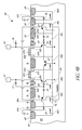
FIG. 4B is an annotated cross section view of the protection device of FIG. 4A, taken along the lines 4B-4B.
FIG. 5A is a schematic perspective view of a bi-directional protection device implementing the protection circuit of FIG. 3 according to another embodiment.
FIG. 5B is a schematic perspective view of a bi-directional protection device implementing the protection circuit of FIG. 3 according to yet another embodiment.
FIG. 6 is a schematic perspective view of a bi-directional protection device implementing the protection circuit of FIG. 3 according to yet another embodiment.
FIG. 7 is a schematic perspective view of a bi-directional protection device implementing the protection circuit of FIG. 3 according to yet another embodiment.
FIG. 8 is a schematic perspective view of a bi-directional protection device implementing the protection circuit of FIG. 3 according to yet another embodiment.
FIG. 9A is a circuit diagram illustrating a bi-directional protection circuit according to another embodiment.
FIG. 9B is a circuit diagram illustrating a bi-directional protection circuit according to yet another embodiment.
FIG. 10A is a schematic perspective view of a bi-directional protection device implementing the protection circuit of FIG. 9A according to one embodiment.
FIG. 10B is an annotated cross section view of the protection device of FIG. 10A, taken along the lines 10B-10B.
FIG. 11A is a schematic perspective view of a bi-directional protection device implementing the protection circuit of FIG. 9A according to another embodiment.
FIG. 11B is a schematic perspective view of a bi-directional protection device implementing the protection circuit of FIG. 9A according to yet another embodiment.
FIG. 12A is a schematic top plan layout view of a protection device according to one embodiment.
FIG. 12B is an enlarged partial top plan layout view of one implementation of the protection device of FIG. 12A.
FIG. 13A is a graph of transmission line pulsing (TLP) laboratory data in a forward direction for one example of the protection device of FIG. 4A.
FIG. 13B is a graph of TLP laboratory data in a reverse direction for one example of the protection device of FIG. 4A.
DETAILED DESCRIPTION OF EMBODIMENTS
The following detailed description of certain embodiments presents various descriptions of specific embodiments of the invention. However, the invention can be embodied in a multitude of different ways as defined and covered by the claims. In this description, reference is made to the drawings where like reference numerals indicate identical or functionally similar elements.
Terms such as above, below, over and so on as used herein refer to a device orientated as shown in the figures and should be construed accordingly. It should also be appreciated that because regions within a semiconductor device (such as a transistor) are defined by doping different parts of a semiconductor material with differing impurities or differing concentrations of impurities, discrete physical boundaries between different regions may not actually exist in the completed device but instead regions may transition from one to another. Some boundaries as shown in the accompanying figures are of this type and are illustrated as abrupt structures merely for the assistance of the reader. In the embodiments described below, p-type regions can include a p-type semiconductor material, such as boron, as a dopant. Further, n-type regions can include an n-type semiconductor material, such as phosphorous, as a dopant. A skilled artisan will appreciate various concentrations of dopants in regions described below.
Certain electronic systems are configured to protect circuits or components therein from transient electrical events. Furthermore, to assure that an electronic system is reliable, manufacturers can test the electronic system under defined stress conditions, which can be described by standards set by various organizations, such as the Joint Electronic Device Engineering Council (JEDEC), the International Electrotechnical Commission (IEC), and the Automotive Engineering Council (AEC). The standards can cover a wide multitude of transient electrical events as discussed above, including ESD events.
Electronic circuit reliability is enhanced by providing protection devices to the pads of an IC. The protection devices can be incorporated on-chip or at the system-level, and can maintain the voltage level at the pads within a predefined safe range by transitioning from a high-impedance state to a low-impedance state when the voltage of the transient electrical event reaches a trigger voltage. Thereafter, the protection device can shunt at least a portion of the current associated with the transient electrical event before the voltage of a transient electrical event reaches a positive or negative failure voltage that can lead to one of the most common causes of damage to the IC. As will be described in detail later with reference to FIG. 2B, after activation, the protection device can remain in the low-impedance state as long as the transient electrical event voltage level is above a positive holding voltage or below a negative holding voltage.
An integrated circuit (IC) can include one or more pads exposed to an operational voltage that can range between a negative voltage and a positive voltage. In certain applications, it is desirable to have a protection device that can protect an internal circuit from both negative and positive transient signals that have a voltage magnitude that is outside normal circuit operating conditions. For example, it can be desirable that the protection device protect an internal circuit against transient signals that exceed the IC power-high and power-low (for instance, ground) voltage levels. Using a protection device to provide protection against both positive and negative transient electrical events can permit a reduction in layout area relative to a design that uses separate structures for protection against positive and negative transient electrical events, thereby enabling a more scalable design solution for low voltage operation. In addition, there is a need for a protection device that can be fine tuned for different current and voltage (I-V) blocking characteristics and able to render protection against positive and negative transient electrical events with fast operational performance and low static power dissipation at the operating voltage conditions.
Overview of Electronic Systems with Protection Devices
FIG. 2A is a schematic block diagram of an electronic system 10, which can include one or more protection devices according to some embodiments. The illustrated electronic system 10 includes an integrated circuit (IC) 11 that includes an input/output protection system 12, an internal circuit 3, a first signal pad or pin 14, a second signal pad 15, a power-high pad or pin 16, a power-low pad or pin 17, a resistor 18, and a supply clamp 8. The internal circuit 3 can be electrically connected to one or more of the pads 14-17. The signal pads 14, 15 can be any suitable pads, including for example, input pads, output pads, and/or bidirectional pads. In certain implementations, the power-low pad 17 is a ground pad. Although only two signal pads, one power-high pad, and one power-low pad are illustrated in FIG. 2A, the IC 11 can include more or fewer signal pads, power-high pads, and/or power-low pads.
The IC 11 can be exposed to transient electrical events, such as ESD events, which can cause IC damage and induce latch-up, such as during a powered-up stress condition. For example, the second signal pad 15 can receive a transient electrical event 9, which can travel along electrical connections of the IC 11 and reach the internal circuit 3. The transient electrical event 9 can produce overvoltage or undervoltage conditions and can dissipate high levels of power, which can disrupt the functioning of the internal circuit 3 and potentially cause permanent damage.
In some embodiments, the input/output protection system 12 can be provided to ensure reliability of the IC 11 by maintaining the voltage level at the pads of the IC 11 within a particular range of voltage, which can vary from pad to pad. The input/output protection system 12 can include one or more protection devices, such as first and second protection devices 13 a, 13 b. The protection devices 13 a, 13 b can be configured to divert a current associated with a transient electrical event received on a pad of the IC to other pads of the IC, thereby providing transient electrical event protection, as will be described in further detail below. When no transient electrical event is present, the protection device can remain in a high-impedance/low-leakage state, thereby reducing static power dissipation resulting from leakage current.
In the configuration illustrated in FIG. 2A, the first protection device 13 a has been electrically connected between the first signal pad 14 and the power-low pad 17, and the second protection device 13 b has been electrically connected between the second signal pad 15 and the power-low pad 17. However, skilled artisans will appreciate that other configurations are possible. For example, in certain implementations, protection devices can be placed, for example, between a power-high pad and a signal pad and/or between a power-high pad and a power-low pad.
The IC 11 can include protection circuitry in addition to the input/output protection system 12. For example, the illustrated IC 11 includes the supply clamp 8, which can be used to maintain the voltage between the power-high pad 16 and the power-low pad 17 within a defined safe range. As shown in FIG. 2A, the resistor 18 has been disposed in a signal path between the power-low pad 17 and the supply clamp 8 and the internal circuit 3. Including the resistor 18 can help prevent latch-up of the internal circuit 3 and/or the supply clamp 8 during power-up testing by reducing majority carrier injection into a substrate used to form the IC 11. Although the IC 11 is illustrated as including the supply clamp 8, in certain implementations, the supply clamp 8 can be omitted.
The input/output protection system 12 can be integrated on-chip with the IC 11. However, in other embodiments, the input/output protection system 12 can be arranged in a separate IC. For example, the input/output protection system 12 can be included in a separately packaged IC, or it can be encapsulated in a common package with the IC 11. In such embodiments, one or more protection devices can be placed in a stand-alone IC, in a common package for system-on-a-package applications, or integrated with an IC in a common semiconductor substrate for system-on-a-chip applications.
The IC 11 can be used in, for example, interface systems, industrial control systems, communication transceiver systems, power management systems, microelectromechanical system (MEMS) sensors, automotive systems, or a variety of other systems. The IC 11 can be utilized in electronic systems in which the pads of the IC are exposed to user contact through a low-impedance connection.
FIG. 2B is a graph 19 showing a relationship between current and voltage of a bi-directional or bi-polar protection device according to one embodiment. As described above, a protection device can be configured to maintain the voltage level at a pad within a predefined safe range. Thus, the protection device can shunt a large portion of the current associated with the transient signal event before the voltage of the transient signal VTRANSIENT reaches either a positive failure voltage +VF or a negative failure voltage −VF that would otherwise cause damage to the IC. Additionally, the protection device can conduct a relatively low amount of current at the normal operating voltage +VOP, thereby reducing or minimizing static power dissipation resulting from the leakage current ILEAKAGE, which enhances the energy efficiency of the IC.
Furthermore, as shown in the graph 19, the protection device can transition from a high-impedance state +ZH to a low-impedance state +ZL when the voltage of the transient signal VTRANSIENT reaches a positive trigger voltage +VTR. Thereafter, the pad circuit can shunt a large amount of current over a wide range of transient electrical event voltage levels. The pad circuit can remain in the low-impedance state +ZL as long as the transient signal voltage level is above a positive holding voltage +VH. By configuring the protection device to have a trigger voltage +VTR and a holding voltage +VH, the protection device can have improved performance while having enhanced stability against unintended activation. In certain implementations, it can be specified for the holding voltage +VH to be above the operating voltage +VOP such that the protection device does not remain in the low-impedance state +ZL after passage of the transient signal event and a return to normal operating voltage levels. Bi-directional operation of the protection device can be important in a variety of applications, including, for example, applications in which an IC has a very low bi-polar (positive and negative) operating voltage at input/output pads that can be potentially stressed during powered-up conditions.
In the illustrated embodiment, the protection device can also shunt a large amount of current for transient signal events having a negative voltage, so that the protection device can provide transient electrical event protection against both negative and positive transient signals. The protection device can transition from a high-impedance state −ZH to a low-impedance state −ZL when the voltage of the transient signal VTRANSIENT reaches a negative trigger voltage −VTR, thereby shunting a large negative amount of current. The pad circuit can remain in the low-impedance state −ZL as long as the voltage magnitude of the negative transient signal is greater than the voltage magnitude of the negative holding voltage −VH.
In FIG. 2B, voltage is expressed along a horizontal axis, and current is expressed along a vertical axis. In the illustrated embodiment, the protection device has I-V characteristics that are symmetrical. In other implementations, the protection devices described herein can have asymmetrical I-V characteristics. For example, protection devices can have different trigger voltages, holding voltages, and/or failure voltages with different I-V curves in the positive and negative regions of the graph.
FIG. 2C is a schematic block diagram of an IC 20 including bi-directional protection devices according to some embodiments. The IC 20 includes the internal circuit 3, the first signal pad 14, the second signal pad 15, the power clamp 8, the first and second protection devices 13 a, 13 b, an input/output transceiver circuit 21, a first output circuit 22, a second output circuit 23, a first arbitration circuit 24, a second arbitration circuit 25, a first resistor 26, a second resistor 27, a third resistor 28, a fourth resistor 29, a control circuit 30, a ground clamp 31, and a first n-type metal oxide semiconductor (NMOS) transistor 32. The illustrated IC 20 can be, for example, an interface IC, such as a half or full duplex communication transceiver IC in which the first and second signal pads 14, 15 are directly exposed to a user in a normal operational environment. As used herein and as persons having ordinary skill in the art will appreciate, MOS transistors can have gates made out of materials that are not metals, such as poly silicon, and can have dielectric regions implemented not just with silicon oxide, but with other dielectrics, such as high-k dielectrics.
The IC 20 can include a plurality of signal lines used for communicating data over an interface. For example, the IC 20 can be configured to communicate using the first and second signal pads 14, 15 using externally connected cables.
The first and second protection devices 13 a, 13 b have been included to aid in providing protection to the IC 20. For example, the first protection device 13 a includes a first end electrically connected to the first signal pad 14 and a second end electrically connected to the first supply voltage V1, which can be, for example, a power-low supply, such as a ground supply. Additionally, the second protection device 13 b includes a first end electrically connected to the second signal pad 15 and a second end electrically connected to the first supply voltage V1. In certain implementations, the ground clamp 31 and/or the fourth resistor 29 can be electrically connected between the first supply voltage V1 and a second supply voltage V2 used to provide ground to transistors not associated with the first and second protection devices 13 a, 13 b. Electrically isolating the first and second supply voltages V1, V2 can serve a variety of functions, including, for example, to help prevent latch-up of the IC 20 during power-up testing by reducing majority carrier injection into a substrate used to form the IC 20.
In certain implementations, the first supply voltage V1 is electrically connected to one or more ground pads and the second supply voltage V2 is electrically connected to one or more different ground pads. The ground clamp 31 can be used to maintain the voltage between the first supply voltage V1 and the second supply voltage V2 within a defined safe range. In one embodiment, the fourth resistor 29 has a resistance in the range of about 0.1Ω and about 1Ω, for example, about 0.5Ω. However, persons having ordinary skill in the art will readily ascertain other suitable resistance values.
The first output circuit 22 and the second output circuit 23 can be used for electrically communicating signals on the first signal pad 14. For example, the first output circuit 22 includes a first end electrically connected to the second supply voltage V2 and a second end electrically connected to the first signal pad 14 through the first resistor 26, and can be used to decrease the voltage of the first signal pad 14, as will be described further below. Additionally, the second output circuit 23 includes a first end electrically connected to the third supply voltage V3 and a second end electrically connected to the first signal pad 14 through the first resistor 26, and can be used to increase the voltage of the first signal pad 14, as will be described further below. In certain implementations, the second supply voltage V2 is electrically connected to one or more power-low pads, such as ground pads, and the third supply voltage V3 is electrically coupled to one or more power-high pads. The first resistor 26 can have any suitable resistance, such as a relatively low resistance selected to be in the range of about 5Ω and about 15Ω, for example, about 10Ω However, persons having ordinary skill in the art will readily ascertain other suitable resistance values, such as resistance values associated with signal processing integrity and/or minimum noise constraints.
The first output circuit 22 includes second to fourth NMOS transistors 33-35. The second NMOS transistor 33 includes a source and body electrically connected to the second supply voltage V2 and a drain electrically connected to a source of the third NMOS transistor 34. The fourth NMOS transistor 35 includes a source electrically connected to a drain of the third NMOS transistor 34 and a drain electrically connected to the first signal pad 14 through the first resistor 26. The third NMOS transistor 34 and the fourth NMOS transistor 35 each further include a body electrically connected to a fourth supply voltage V4. In certain implementations, the fourth supply voltage V4 is selected to be a voltage below the second supply voltage V2, and can have a magnitude selected to help achieve the target signaling performance of the IC 20. For example, the signaling conditions on the first signal pad may include positive and negative voltage signaling levels, and the fourth supply voltage V4 can be used to prevent the bodies of the third and fourth NMOS transistor 34, 35 from becoming forward-biased when the first signal pad 14 has a relatively low voltage level. In one implementation, the voltage on the first signal pad 14 ranges between about −1 V and about 3.4 V during normal operation.
The second to fourth NMOS transistors 33-35 each further include a gate that can be controlled using the control circuit 30. In certain implementations, the gate of the second NMOS transistor 33 is controlled to a voltage level corresponding to a desired sink current of the first output circuit 22, the gate of the third NMOS transistor 34 is controlled to a voltage level corresponding to a desired resistance of the third NMOS transistor 34 so as to boost the output impedance of the first output circuit 22, and the gate of the fourth NMOS transistor 35 is used to turn the first output circuit 22 on and off to generate a signal on the first signal pad 14.
The second output circuit 23 includes first and second p-type metal oxide semiconductor (PMOS) transistors 36, 37. The first PMOS transistor 36 includes a source and a body electrically connected to the third supply voltage V3 and a drain electrically connected to a source of the second PMOS transistor 37. The second PMOS transistor 37 further includes a drain electrically connected to the first signal pad 14 through the first resistor 26. The second PMOS transistor 37 further includes a body electrically connected to a fifth supply voltage V5. In certain implementations, the fifth supply voltage V5 is selected to be a voltage above the third supply voltage V3, and can have a magnitude selected to help prevent the body of the second PMOS transistor 37 from becoming forward-biased when the voltage of the first signal pad 14 increases above the third supply voltage V3. The first and second PMOS transistors 36, 37 each include a gate that can be controlled using the control circuit 30. In certain implementations, the gate of the first PMOS transistor 36 is controlled to a voltage level corresponding to a desired source current of the second output circuit 23 and the gate of the second PMOS transistor 37 is used to turn the second output circuit 23 on and off to generate a signal on the first signal pad 14.
The internal circuit 3 and the first NMOS transistor 32 can be used to sense signals received on the first signal pad 14. For example, the first NMOS transistor 32 includes a drain electrically connected to the internal circuit 3 and a source electrically connected to the first signal pad 14 through the first and third resistors 26, 28. The first NMOS transistor 32 can be used to control the impedance between the internal circuit 3 and the first signal pad 14, thereby allowing a voltage level on the first signal pad 14 to be sensed by the internal circuit 3. For example, the control circuit 30 can be used to control the potential of the gate of the first NMOS transistor 32 to a level suitable for the internal circuit 3 to sense a signal received on the first signal pad 14. As illustrated in FIG. 2C, the first NMOS transistor 32 can include a body electrically connected to the fourth potential V4.
In certain implementations, the first and second arbitration circuits 24, 25 can be included to generate the fourth and fifth supply voltages V4, V5, respectively. For example, the first arbitration circuit 24 can be configured to generate the fourth supply voltage V4 such that the supply has a voltage level equal to about the lesser of the second supply voltage V2 and the voltage of the first signal pad 14. Additionally, the second arbitration circuit 25 can be configured to generate the fifth supply voltage V5 such that the supply has a voltage level equal to about the greater of the third supply voltage V3 and the voltage of the first signal pad 14. Inclusion of the first and second arbitration circuits 24, 25 can aid in permitting the voltage at the first signal pad 14 to fall below the second supply voltage V2 and to increase above the third supply voltage V3 during signaling.
The first arbitration circuit 24 includes a fifth NMOS transistor 41, a sixth NMOS transistor 42, a seventh NMOS transistor 43, a fifth resistor 44, and a sixth resistor 45. The fifth NMOS transistor 41 includes a drain electrically connected to the second supply voltage V2 and a source and body electrically connected to a source and body of the sixth NMOS transistor 42 and to a first end of the sixth resistor 45. The sixth resistor 45 further includes a second end electrically connected to a drain of the seventh NMOS transistor 43. The seventh NMOS transistor 43 further includes a source and a body electrically connected to the fourth supply voltage V4. The fifth resistor 44 includes a first end electrically connected to a drain of the sixth NMOS transistor 42 and a second end electrically connected to the first signal pad 14 through the first resistor 26. The fifth to seventh NMOS transistors 41-43 each further include a gate, which can be controlled using, for example, the control circuit 30.
The second arbitration circuit 25 includes a third PMOS transistor 46, a fourth PMOS transistor 47, a fifth PMOS transistor 48, a seventh resistor 49, and an eighth resistor 50. The third PMOS transistor 46 includes a drain electrically connected to the third supply voltage V3 and a source and body electrically connected to a source and body of the fourth PMOS transistor 47 and to a first end of the eighth resistor 50. The eighth resistor 50 further includes a second end electrically connected to a drain of the fifth PMOS transistor 48. The fifth PMOS transistor 48 further includes a source and a body electrically connected to the fifth supply voltage V5. The third to fifth PMOS transistors 46-48 each further include a gate, which can be controlled using, for example, the control circuit 30. The seventh resistor 49 includes a first end electrically connected to a drain of the fourth PMOS transistor 47 and a second end electrically connected to the first signal pad 14 through the first resistor 26.
When a transient electrical event is received on the first signal pad 14, the voltage of the first signal pad 14 can increase until a trigger voltage of the first protection device 13 a is reached (see FIG. 2B). However, in certain implementations, there can be an overshoot of voltage on the first signal pad 14 before the first protection device 13 a activates.
In one embodiment, the first and second arbitration circuits 24, 25 and the first and second output circuits 22, 23 are configured to have a trigger voltage greater than an overshoot voltage of the first protection device 13 a to aid in preventing the arbitration circuits 24, 25 and/or the output circuits 22, 23 from breaking down before the first protection device 13 a activates during a transient electrical event. In one implementation, at least two p-n junctions are disposed in each electrical path between the first signal pad 14 and the second supply voltage V2. Configuring the core circuitry of the IC 20 in this manner can prevent a parasitic path between the first signal pad 14 and the second supply voltage V2 from activating before the first protection device 13 a turns on during the high energy transient electrical event. As shown in FIG. 2C, at least two p-n junctions can be provided between the first signal pad 14 and the second supply voltage V2 by cascading MOS transistor devices. In certain implementations, the power clamp 8 can include a p-n junction, and the second output circuit 23 can include a fewer number of devices in a cascade than the first output circuit 22.
The fifth and seventh resistors 44, 49 can be included in the first and second arbitration circuits 24, 25, respectively, to aid in increasing the impedance in parasitic electrical paths between the first signal pad 14 and the second supply voltage V2 through the first and second arbitration circuits 24, 25. In one implementation, the fifth and seventh resistors 44, 49 each have a resistance selected to be in the range of about 30Ω and about 85Ω, for example, about 72Ω. However, persons having ordinary skill in the art will readily ascertain other suitable resistance values.
The sixth and eighth resistors 45, 50 can also aid in increasing the impedance in parasitic paths between the first signal pad 14 and the second supply voltage V2 through the first and second arbitration circuits 24, 25, as well as to aid the first and second arbitration circuits 24, 25 in generating the fourth and fifth supply voltages V4, V5, respectively. In certain implementations, the sixth and eighth resistors 45, 50 each have a resistance selected to be in the range of about 30Ω and about 85Ω, for example, about 75Ω. However, persons having ordinary skill in the art will readily ascertain other suitable resistance values.
The second signal pad 15 is electrically connected to the input/output processing circuit 21 through the second resistor 27. For example, the second resistor 27 includes a first end electrically connected to the second signal pad 15 and a second end electrically connected to the input/output processing circuit 21. In certain implementations, the input/output processing circuit 21 includes circuitry similar to that shown electrically connected to the first signal pad 14. However, input/output processing circuit 21 need not be the same as the circuitry shown electrically connected to the first signal pad 14. In certain implementations, the second resistor 27 has a resistance selected to be in the range of about 5Ω and about 15Ω, for example, about 10Ω. However, persons having ordinary skill in the art will readily ascertain other suitable resistance values.
Although the protection devices 13 a, 13 b have been illustrated in the context of a transceiver IC, the protection devices described herein can be used in a wide range of ICs and other electronics.
Overview of Bi-Directional Protection Devices
FIG. 3 is a circuit diagram illustrating a bi-directional protection circuit 60 according to one embodiment. The illustrated protection circuit 60 is electrically connected between a first pad 61 and a second pad 62, and can be used to, for example, provide low bi-directional blocking voltage protection. The bi-directional protection circuit 60 includes a bi-directional bipolar transistor 63, first and second NPN bipolar transistors 64, 65, first and second PNP bipolar transistors 66, 67, and first to eighth resistors 71-78. The protection circuit 60 can be adapted to serve, for example, any of the protection devices 13 a, 13 b of FIGS. 2A and 2C.
The protection circuit 60 can be electrically coupled between the first and second pads 61, 62 such that a current shunt path can be established between the pads when there is an overvoltage or undervoltage condition. For example, the first pad can be a signal pad of an IC, such as the first and second signal pads 14, 15 of FIG. 2A, and the second pad can be a power-low pad, such as the power-low pad 17 of FIG. 2A. The protection circuit 60 can provide a low-impedance path between the signal pad and the power-low pad during a transient electrical event. In certain implementations, the second pad 62 is a ground pad.
The first NPN bipolar transistor 64 includes an emitter electrically connected to a first end of the seventh resistor 77 and to the first pad 61. The first NPN bipolar transistor 64 further includes a base electrically connected to an emitter/collector E/C of the bi-directional bipolar transistor 63 and to a first end of the first resistor 71. The first resistor 71 further includes a second end electrically connected to a second end of the seventh resistor 77 and to a first end of the third resistor 73. The second NPN bipolar transistor 65 includes an emitter electrically connected to a first end of the eighth resistor 78 and to the second pad 62. The second NPN bipolar transistor 65 further includes a base electrically connected to a collector/emitter C/E of the bi-directional bipolar transistor 63 and to a first end of the second resistor 72. The second resistor 72 further includes a second end electrically connected to a second end of the eighth resistor 78 and to a first end of the fourth resistor 74. The bi-directional bipolar transistor 63 further includes a base electrically connected to a collector of the first NPN bipolar transistor 64, to a collector of the second NPN bipolar transistor 65, to a base of the first PNP bipolar transistor 66, and to a base of the second PNP bipolar transistor 67. In certain implementations, the base of the bi-directional bipolar transistor 63 is formed from an n-well that is electrically connected to a floating n-type isolation layer. The first PNP bipolar transistor 66 further includes an emitter electrically connected to a second end of the third resistor 73 and a collector electrically connected to a first end of the fifth resistor 75. The second PNP bipolar transistor 67 further includes an emitter electrically connected to a first end of the fourth resistor 74 and a collector electrically connected to a first end of the sixth resistor 76. The sixth resistor 76 further includes a second end electrically connected to a second end of the fifth resistor 75 and to the first supply voltage V1, which can be, for example, a ground node. In certain implementations, the second ends of the fifth and sixth resistors 75, 76 are electrically connected to a p-type guard ring.
The bi-directional bipolar transistor 63 can operate bi-directionally, and an operation of the emitter/collector E/C and the collector/emitter C/E as emitter and collector can depend on the voltage conditions of the first and second pads 61, 62. For example, when a voltage difference between the first pad 61 and the second pad 62 is greater than about a positive trigger voltage +VTR (see FIG. 2B) of the protection circuit 60, the emitter/collector E/C of the bi-directional bipolar transistor 63 serves as an emitter and the collector/emitter C/E of the bi-directional bipolar transistor serves as a collector. In contrast, when a voltage difference between the first pad 61 and the second pad 62 is less than about a negative trigger voltage −VTR (see FIG. 2B) of the protection circuit 60, the emitter/collector E/C of the bi-directional bipolar transistor 63 serves as a collector and the collector/emitter C/E of the bi-directional bipolar transistor 63 serves as an emitter.
In certain implementations, the bi-directional bipolar transistor 63 can be a PNP bipolar transistor configured to control the response and current discharge of the protection circuit 60 during an overvoltage or undervoltage condition. For example, the first and second NPN bipolar transistors 64, 65 can be configured to have limited injection efficiency at their emitter-base junctions, thereby allowing the bi-directional bipolar transistor 63 to substantially control the response characteristic.
The first to sixth resistors 71-76 can be formed using, for example, the resistivity of doped regions to achieve the target resistances. For example, in one embodiment, the first to sixth resistors 71-76 are implemented by using the resistivity of n-type or p-type wells desired to achieve a turn-on speed and stability desired for a particular application. For example, the resistance of the first and second resistors 71, 72 can be selected to obtain a desired build-up to forward-bias the emitter-base junctions of the first and second NPN bipolar transistors 64, 65, respectively. In one implementation, the first and second resistors 71, 72 each have a resistance selected to be in the range of about 0.25Ω and about 8Ω, for example, about 2Ω, the third and fourth resistors 73, 74 each have a resistance selected to be in the range of about 15Ω and about 45Ω, for example, about 20Ω, and the fifth and sixth resistors 75, 76 each have a resistance selected to be in the range of about 15Ω and about 40Ω, for example, about 30Ω. However, persons having ordinary skill in the art will readily ascertain other suitable resistance values.
In certain implementations, the resistance between the base-emitter junctions of the first and second NPN bipolar transistors 64, 65 is enhanced by including additional resistor components. For example, as shown in FIG. 3, the seventh and eighth resistors 77, 78 can be electrically connected in series with the first and second resistors 71, 72, respectively, to aid in increasing the resistance between the base-emitter junctions of the first and second NPN bipolar transistors 64, 65. In one embodiment, the seventh and eight resistors 77, 78 comprise polysilicon resistors disposed above a surface of a substrate in which the bipolar transistors 63-67 and resistors 71-76 are formed. In one implementation, the seventh and eighth resistors 77, 78 each have a resistance selected to be in the range of about 0.2Ω and about 200Ω, for example, about 0.5Ω. However, persons having ordinary skill in the art will readily ascertain other suitable resistance values, including, for example, resistance values selected to reduce the trigger voltage of the protection circuit.
FIG. 4A is a schematic perspective view of a bi-directional protection device 80 implementing the protection circuit 60 of FIG. 3 according to one embodiment. The protection device 80 includes a p-type substrate 81, first to fourth p-wells 82 a-82 d, first to sixth p-type active areas 83 a-83 f, first to third n-wells 84 a-84 c, first to fourth n-type active areas 85 a-85 d, first and second gate oxide layers 86 a, 86 b, first and second gate layers 87 a, 87 b, oxide regions 88, and n-type isolation layer 89.
As illustrated in FIG. 4A, the substrate 81 has the first to third n-wells 84 a-84 c and the first to fourth p-wells 82 a-82 d formed therein. The second and third p- wells 82 b, 82 c are disposed on opposite sides of the second n-well 84 b. The first n-well 84 a is disposed on a side of the second p-well 82 b opposite the second n-well 84 b. The third n-well 84 c is disposed on on a side of the third p-well 82 c opposite the second n-well 84 b. The n-type isolation layer 89 is disposed beneath the second n-well 84 b, the second and third p- wells 82 b, 82 c, and beneath a portion of the first and third n- wells 84 a, 84 c. The first p-well 82 a is formed adjacent the first n-well 84 a on a side of the first n-well 84 a opposite the second p-well 82 b. The fourth p-well 82 d is formed adjacent the third n-well 84 c on a side of the third n-well 84 c opposite the third p-well 82 c. In the illustrated configuration, the first and fourth p- wells 82 a, 82 d are spaced from the first and third n- wells 84 a, 84 c, respectively, such that the first p-well 82 a does not abut the first n-well 84 a and the fourth p-well 82 d does not abut the third n-well 84 c. However, other implementations are possible.
The first and sixth p-type active areas 83 a, 83 f are disposed in the first and fourth p- wells 82 a, 82 d, respectively. The first and fourth n-type active areas 85 a, 85 d are disposed in the first and third n- wells 84 a, 84 c, respectively. The first and second gate oxide layers 86 a, 86 b are disposed on the surface of the substrate 81 over the second and third p- wells 82 b, 82 c, respectively. The first and second gate layers 87 a, 87 b are disposed over the first and second gate oxide layers 86 a, 86 b, respectively, and can be polysilicon layers. The third p-type active area 83 c is disposed on a first side of the first gate layer 87 a, and includes a first portion disposed in the second p-well 82 b and a second portion disposed in the second n-well 84 b. The second n-type active area 85 b is disposed in the second p-well 82 b on a second side of the first gate layer 87 a opposite the first side. The fourth p-type active area 83 d is disposed on a first side of the second gate layer 87 b, and includes a first portion disposed in the third p-well 82 c and a second portion disposed in the second n-well 84 b. The third n-type active area 85 c is disposed in the third p-well 82 c on a second side of the first gate layer 87 b opposite the first side. The second p-type active area 83 b is disposed in the second p-well 82 b on a side of the second n-type active area 85 b opposite the first gate layer 87 a. The fifth p-type active area 83 e is disposed in the third p-well 82 c on a side of the third n-type active area 85 c opposite the second gate layer 87 b.
In the illustrated embodiment, the protection device 80 is formed in the substrate 81, which can be a p-type substrate. In another embodiment, the substrate can include a p-type epitaxial layer formed on a silicon (Si) substrate. Although not illustrated in FIG. 4A, the substrate 81 can also include other devices or structures formed therein.
In one embodiment, the p-wells 82 a-82 d and the n-wells 84 a-84 c can be similar to one another, and can have a depth ranging between about 1.5 μm and about 5.5 μm from the surface 90 of the substrate 81. In one implementation, the p-type active areas 83 a-83 f and n-type active areas 85 a-85 d have a depth that is about 15 times to about 25 times less than a depth of the well within which the active area is formed. The oxide regions 88 can have any suitable depth, such as depth that is about 5 times to about 15 times less than the depth of the p-wells 82 a-82 d. In certain implementations, the oxide regions 88 can be relatively deeper than the p-type active areas 83 a-83 f and n-type active areas 85 a-85 d.
In the illustrated embodiment, the second p-type active area 83 b includes a plurality of island regions 83 b 1 disposed along the x-direction, and the fifth p-type active area 83 e includes a plurality of island regions 83 e 1 disposed along the x-direction. Additionally, the second n-type active area 85 b includes an elongated region 85 b 2 extending in the x-direction and a plurality of protruding regions 85 b 1 that extend in the y-direction away from the gate layer 87 a. As shown in FIG. 4A, each of the protruding regions 85 b 1 extends between two of the island regions 83 b 1. Similarly, the third n-type active area 85 c includes an elongated region 85 c 2 extending in the x-direction and a plurality of protruding regions 85 c 1 extending in the y-direction away from the gate layer 87 b. Each of the protruding regions 85 c 1 extends between two of the island regions 83 e 1. Configuring the second and fifth p- type actives areas 83 b, 83 e and the second and third n-type active areas 85 b, 85 c in this manner can aid in reducing the holding and/or trigger voltage of the protection device 80, as will be described in further detail below. While illustrated and described with reference to x-directions, y-directions, and z-directions, it will be understood that the directions can be interchanged and can vary based on view.
The first and third n- wells 84 a, 84 c and the n-type isolation layer 89 can aid in electrically isolating the second and third p- wells 82 b, 82 c from the substrate 81, thereby permitting the p-type substrate 81 and the second and third p- wells 82 b, 82 c to operate at different electrical potentials. As used herein, and as will be understood by one of skill in the art, the term “n-type isolation layer” refers to any suitable n-type isolation layer, including, for example, those used in silicon-on-insulator (SOI) technologies, buried n-layer technologies, or in deep n-well technologies. In certain implementations described herein, the first to third n-wells 84 a-84 c and the n-type isolation layer 89 are configured to be electrically floating. Although the bi-directional protection device 80 is illustrated as including the first and third n- wells 84 a, 84 c and the n-type isolation layer 89, in certain implementations, the bi-directional protection device 80 can be isolated from a substrate in other ways. For example, isolation can be achieved when using silicon-on-insulator (SOI) processes by using dielectric structures. SOI processes can be employed in a variety of applications, including, for example, applications having high robustness requirements.
The first and fourth p- wells 82 a, 82 d and the first and sixth p-type active areas 83 a, 83 f can form a guard ring around the protection device 80. The guard ring can be employed to eliminate the formation of unintended parasitic paths between the protection device 80 and surrounding semiconductor components when integrated on-chip.
The illustrated bi-directional protection device 80 includes the oxide regions 88. Formation of the isolation regions can involve etching trenches in the substrate 81, filling the trenches with a dielectric, such as silicon dioxide (SiO2), and removing the excess dielectric using any suitable method, such as chemical-mechanical planarization. In certain implementations, the oxide regions 88 can be shallow trench regions, deep trench regions or local oxidation of silicon (LOCOS) regions disposed between active areas.
The protection device 80 can undergo back end processing to form contacts and metallization. Skilled artisans will appreciate that these details have been omitted from this figure for clarity.
FIG. 4B is a cross section view of the protection device 80 of FIG. 4A, taken along the lines 4B-4B. The protection device 80 includes the p-type substrate 81, the first to fourth p-wells 82 a-82 d, the first to sixth p-type active areas 83 a-83 f, the first to third n-wells 84 a-84 c, the first to fourth n-type active areas 85 a-85 d, the first and second gate oxide layers 86 a, 86 b, the first and second gate layers 87 a, 87 b, the oxide regions 88, and the n-type isolation layer 89, which can be as described above with respect to FIG. 4A.
The cross section has been annotated to show examples of circuit devices formed from the illustrated structure, such as the bi-directional bipolar transistor 63, the first and second NPN bipolar transistors 64, 65, the first and second PNP bipolar transistors 66, 67, and the first to sixth resistors 71-76. Additionally, the cross section has been annotated to show the seventh and eighth resistors 77, 78, which can be included in certain implementations, and which can be formed by using, for example, n-diffusion and/or poly silicon. Furthermore, the cross section has been annotated to show the first and second pads 61, 62 as well as electrical connections within the protection device 80 and to the pads.
The first pad 61 is electrically connected to a first end of the seventh resistor 77 and to the second n-type active area 85 b. The seventh resistor 77 further includes a second end electrically connected to the second p-type active area 83 b. The second pad 62 is electrically connected to a first end of the eighth resistor 78 and to the third n-type active area 85 c. The eighth resistor 78 further includes a second end electrically connected to the fifth p-type active area 83 e. The first n-type active area 85 a is electrically connected to the fourth n-type active area 85 d. The first and sixth p-type active areas 83 a, 83 f are electrically connected to the first supply voltage V1.
The bi-directional bipolar transistor 63 can be formed from the second n-well 84 b and the second and third p- wells 82 b, 82 c. For example the bi-directional bipolar transistor 63 can have an emitter/collector E/C formed from the second p-well 82 b, a base formed from the second n-well 84 b, and a collector/emitter C/E formed from the third p-well 82 c. The first and second NPN bipolar transistors 64, 65 can be formed from the second and third n-type active areas 85 b, 85 c, from the second and third p- wells 82 b, 82 c, and from the n-type isolation layer 89, and can be vertical parasitic NPN bipolar devices. For example, the first NPN bipolar transistor 64 can have an emitter formed from the second n-type active area 85 b, a base formed from the second p-well 82 b, and a collector formed from the n-type isolation layer 89. Additionally, the second NPN bipolar transistor 65 can have an emitter formed from the third n-type active area 85 c, a base formed from the third p-well 82 c, and a collector formed from the n-type isolation layer 89. The first and second PNP bipolar transistors 66, 67 can be formed from the first to fourth p-wells 82 a-82 d and the first and third n- wells 84 a, 84 c, and can be lateral parasitic PNP bipolar devices. For example, the first PNP bipolar transistor 66 can have an emitter formed from the second p-well 82 b, a base formed from the first n-well 84 a, and a collector formed from the first p-well 82 a. Additionally, the second PNP bipolar transistor 67 can have an emitter formed from the third p-well 82 c, a base formed from the third n-well 84 c, and a collector formed from the fourth p-well 82 d.
The first and third resistors 71, 73 can be formed from the resistance of the second p-well 82 b, and the second and fourth resistors 72, 74 can be formed from the resistance of the third p-well 82 c. Additionally, the fifth resistor 75 can be formed from the resistance between the collector of the first PNP bipolar transistor 66 and the first p-type active area 83 a, and the sixth resistor 76 can be formed from the resistance between the collector of the second PNP bipolar transistor 67 and the sixth p-type active area 83 f The seventh and eighth resistors 77, 78 can be included in certain implementations, and can represent the resistance of the polysilicon, diffusion, and/or other material from which the seventh and eight resistors 77, 78 are formed. However, the seventh and eight resistors 77, 78 can be omitted in certain embodiments.
Persons having ordinary skill in the art will appreciate that the cross section shown in FIG. 4B can correspond to the protection circuit 60 shown in FIG. 3. Although the protection device 80 of FIGS. 4A-4B illustrates one implementation of the protection circuit 60 of FIG. 3, other implementations are possible.
The third and fourth p-type active areas 83 c, 83 d can aid in controlling the trigger voltage of the bi-directional protection device 80. For example, the third and fourth p-type active areas 83 c, 83 d can have a higher doping concentration than the second and third p- wells 82 c, 82 d, respectively, and thus can be used to control the breakdown voltage of the bi-directional PNP bipolar transistor 63. Additionally, in certain implementations, the third and fourth p-type active areas 83 c, 83 d can also impact the holding voltage of the bi-directional protection device 80. As shown in FIG. 4B, the third and fourth p-type active areas 83 c, 83 d can be configured to be electrically floating.
With reference to FIGS. 4A-4B, the second and third n-type active areas 85 b, 85 c can serve as electron injection centers and recombination centers for holes injected into the second and third p- wells 82 b, 82 c, respectively. By configuring the second n-type active area 85 b to include elongated portions 85 b 1 that extend between island regions 83 b 1 of the second p-type active area 83 b, and by configuring the third n-type active area 85 c to include elongated portions 85 c 1 that extend between island regions 83 e 1 of the fifth p-type active area 83 e, the operation of the second and third n-type active areas 85 b, 85 c as electron injection centers and hole recombination centers can be enhanced. By enhancing the injection of electrons and recombination of holes, the gain of the bi-directional bipolar transistor 63 can be enhanced. Furthermore, increasing the injection of electrons and recombination of holes can adjust the holding voltage such that the risk of latch-up is reduced. Additionally, forming the second and fifth p-type active areas 83 b, 83 e from the island regions 83 b 1, 83 e 1, respectively, can increase the resistance of the second and third p- wells 82 b, 82 c and increase the build-up of the base-emitter voltages of the first and second NPN bipolar transistors 64, 65, thereby expediting the clamping speed of the protection device during a transient electrical event, including, for example, the clamping speed in low voltage applications.
With reference back to FIG. 4B, the protection device 80 has been annotated to show various dimensions of the wells, regions, and layers described above. In FIG. 4B, the protection device 80 is symmetrical. Accordingly, although dimensions are described below with respect to the left half of the device, the right half of the device can have the same dimensions. Persons having ordinary skill in the art will appreciate that the teachings herein are also applicable to asymmetric devices. For example, asymmetrical structures can be provided by arranging the wells, active regions, and/or other structures of the device in an asymmetric configuration.
A first spacing d1 between the second p-type active area 83 b and the second n-type active area 85 b can be selected to be a relatively short distance, such as the minimum spacing permitted by the process technology. Selecting the spacing d1 to be relatively short can improve the operation of the second n-type active area 85 b as a recombination center for holes injected into the second p-well 82 b. The operation of the second n-type active area 85 b as a recombination center for holes can be further enhanced by configuring the second n-type active area 85 b to include elongated portions 85 b 1 that extend between island regions 83 b 1 of the second p-type active area 83 b, as was described above with respect to FIG. 4A. Reducing the first spacing d1 can be used to fine tune the trigger voltage of the protection device 80 while achieving a reduction in area. In certain implementations, the first spacing d1 can be selected to be in the range of about 0 μm (abutting) to about 1.5 μm, for example, about 1 μm. However, other dimensions will be readily determined by one of skill in the art.
A second spacing d2 between an edge of the first n-type active area 85 a and an edge of the second p-well 82 b can be selected to be sufficiently large to avoid the first PNP bipolar transistor 66 of FIG. 3 from breaking down between the first p-well 82 a and the second p-well 82 b during a transient electrical event. Likewise, a third second spacing d3 between an edge of the second p-type active area 83 b and an edge of the first n-well 84 a can be selected to be sufficiently large to avoid the first PNP bipolar transistor 66 of FIG. 3 from breaking down between the first p-well 82 a and the second p-well 82 b during a transient electrical event. In certain implementations, the second spacing d2 can be selected to be in the range of about 1.5 μm to about 3 μm, for example, about 2.75 μm, and the third spacing d3 can be selected to be in the range of about 1.5 μm to about 3 μm, for example, about 2.5 μm. However, other dimensions will be readily determined by one of skill in the art.
A fourth spacing d4 has been used to denote a distance between an edge of the first p-type active area 83 a and an edge of the first p-well 82 a facing the first n-well 84 a and a distance between an edge of the first n-type active area 85 a and an edge of the first n-well 84 a facing the first p-well 82 a. In certain implementations, the fourth spacing d4 can be selected to be in the range of about 1.5 μm to about 3 μm, for example, about 2.5 μm. However, other dimensions will be readily determined by one of skill in the art. Additionally, in certain implementations, the distance between the edge of the first p-type active area 83 a and the edge of the first p-well 82 a and the distance between the edge of the first n-type active area 85 a and the edge of the first n-well 84 a need not be the same.
A fifth spacing d5 representing the width of the second n-well 84 b can be selected based on a desired holding voltage characteristics of the bi-directional bipolar transistor 63. In certain low voltage implementations, the fifth spacing d5 can be selected to be in the range of about 2 μm to about 6 μm, for example, about 3.5 μm. However, other dimensions will be readily determined by one of skill in the art.
A sixth spacing d6 has been used to denote a distance between the first p-well 82 a and the first n-well 84 a. The sixth spacing d6 can be increased to increase breakdown voltage of the protection device 80 to the substrate 81, which can aid in preventing the device 80 from getting damaged or injecting current into to the substrate when the device is stressed at relatively high signaling conditions, such as at 30 A peak currents and 15 kV peak voltages associated with IEC61000-4-2 stress conditions. In certain implementations, the sixth spacing d6 can be selected to be in the range of about 0 μm to about 2 μm, for example, about 1 μm. However, other dimensions will be readily determined by one of skill in the art.
A seventh spacing d7 has been used to denote a distance between an edge of the first n-well 84 a and an edge of the n-type isolation layer 89. In certain implementations, the seventh spacing d7 can be selected to be in the range of about 0 μm (aligned) to about 2.5 μm, for example, about 2.25 μm. However, other dimensions will be readily determined by one of skill in the art.
The protection device 80 includes the gate layers 87 a, 87 b, which have been used to define edges of the second and third n-type active areas 85 b, 85 c and the third and fourth p-type active areas 83 c, 83 d. For example, the second n-type active area 85 b and the third p-type active area 83 c have been formed on opposite sides of the first gate layer 87 a, and the third n-type active area 85 c and the fourth p-type active area 83 d have been formed on opposite sides of the second gate layer 87 b. Accordingly, the gate layers 87 a, 87 b can serve as implant blocking structures in certain implementations. In the illustrated configuration, the protection device 80 does not include metal oxide semiconductor (MOS) transistor devices, since active areas of different doping polarities have been formed on opposing sides of the first and second gate layers 87 a, 87 b. Rather, the gate layers 87 a, 87 b have been used as an implant mask when doping the second and third n-type active areas 85 b, 85 c and the third and fourth p-type active areas 83 c, 83 d. Although an oxide region can be used to define the edges of the second and third n-type active areas 85 b, 85 c and the third and fourth p-type active areas 83 c, 83 d in some implementations, using gate layers to define these regions can permit a relatively larger carrier concentration to flow near the surface 90 of the substrate 81, thereby permitting the protection device 80 to have enhanced current handling capability, faster turn-on speed, and/or a lower trigger voltage.
In one embodiment, the protection device 80 can have a trigger voltage of about +/−(3-14) V and a holding voltage in the range of +/−(1.5-10) V. Accordingly, the protection device 80 can provide protection to ICs having low trigger and holding voltage requirements, such as ICs including pins that operate under very low common mode voltage and low signal processing noise conditions while operating in harsh environments. The protection device 80 can provide protection against an ESD event in the typical range of 2,000 to 8,000 V ESD stress condition while reducing the protection device footprint in a variety of applications, including, for example, in very low voltage operation interface applications.
FIG. 5A is a schematic perspective view of a bi-directional protection device 95 implementing the protection circuit 60 of FIG. 3 according to another embodiment. The protection device 95 includes the p-type substrate 81, the first to fourth p-wells 82 a-82 d, the first to sixth p-type active areas 83 a-83 f, the first to third n-wells 84 a-84 c, the first to fourth n-type active areas 85 a-85 d, the first and second gate oxide layers 86 a, 86 b, the first and second gate layers 87 a, 87 b, the oxide regions 88, and the n-type isolation layer 89.
The protection device 95 of FIG. 5A can be similar to the protection device 80 described above with reference to FIGS. 4A-4B. However, in contrast to the protection device 80 of FIGS. 4A-4B, the second and fifth p-type active areas 83 b, 83 e and the second and third n-type active areas 85 b, 85 c have been arranged in a different layout configuration. For example, in the implementation illustrated in FIG. 5A, the second and fifth p-type active areas 83 b, 83 e and the second and third n-type active areas 85 b, 85 c each are formed from channels extending along the x-direction parallel to the first and second gate layers 87 a, 87 b. Configuring the second and fifth p-type active areas 83 b, 83 e and the second and third n-type active areas 85 b, 85 c in this manner can be used to increase the trigger and lowering the holding voltages of the protection device 95 of FIG. 5A relative to the protection device 80 of FIGS. 4A-4B.
FIG. 5B is a schematic perspective view of a bi-directional protection device 100 implementing the protection circuit 60 of FIG. 3 according to yet another embodiment. The protection device 100 includes the p-type substrate 81, the first to fourth p-wells 82 a-82 d, the first to sixth p-type active areas 83 a-83 f, the first to third n-wells 84 a-84 c, the first to fourth n-type active areas 85 a-85 d, the first and second gate oxide layers 86 a, 86 b, the first and second gate layers 87 a, 87 b, the oxide regions 88, and the n-type isolation layer 89.
The protection device 100 of FIG. 5B can be similar to the protection device 80 described above with reference to FIGS. 4A-4B. However, in contrast to the protection device 80 of FIGS. 4A-4B, the second and fifth p-type active areas 83 b, 83 e and the second and third n-type active areas 85 b, 85 c have been arranged in a configuration that is complementary. For example, in the implementation illustrated in FIG. 5B, the second n-type active area 85 b includes a plurality of island regions disposed along the x-direction and the second p-type active area 83 b includes an elongated region disposed along the x-direction and protruding regions extending in the y-direction such that each of the protruding regions extends between two of the island regions. Similarly, the third n-type active area 85 c includes a plurality of island regions disposed along the x-direction and the fifth p-type active area 83 e includes an elongated region disposed along the x-direction and protruding regions extending in the y-direction such that each of the protruding regions extends between two of the island regions. Configuring the second and fifth p-type active areas 83 b, 83 e and the second and third n-type active areas 85 b, 85 c in this manner can be used to increase the trigger and holding voltages of the protection device 100 of FIG. 5B relative to the protection device 80 of FIGS. 4A-4B and the protection device 95 of FIG. 5A.
FIG. 6 is a schematic perspective view of a bi-directional protection device 110 implementing the protection circuit 60 of FIG. 3 according to yet another embodiment. The protection device 110 includes the p-type substrate 81, the first to fourth p-wells 82 a-82 d, the first to sixth p-type active areas 83 a-83 f, the first to third n-wells 84 a-84 c, first to fifth n-type active areas 85 a-85 e, the first and second gate oxide layers 86 a, 86 b, the first and second gate layers 87 a, 87 b, the oxide regions 88, and the n-type isolation layer 89.
The protection device 110 of FIG. 6 can be similar to the protection device 100 described above with reference to FIG. 5B. However, in contrast to the protection device 100 of FIG. 5B, the protection device 110 further includes the fifth n-type active area 85 e disposed between the third and fourth p-type active areas 83 c, 83 d in the second n-well 84 b. Including the fifth n-type active area 85 e in the second n-well 84 b can increase the concentration of electrons in the second n-well 84 b, thereby enhancing the conduction of the bi-directional bipolar transistor 63, including the surface conduction of the transistor. The inclusion of the fifth n-type active area 85 e can also increase n-type doping in the second n-well 84 b, which can increase electron concentration in the base of the bi-directional bipolar transistor 63 of FIG. 4B, thereby helping to control the bipolar device gain and fine-tuning the protection device activation breakdown.
FIG. 7 is a schematic perspective view of a bi-directional protection device 120 implementing the protection circuit 60 of FIG. 3 according to yet another embodiment. The protection device 120 includes the p-type substrate 81, the first to fourth p-wells 82 a-82 d, the first and second p-type active areas 83 a, 83 b, the fifth and sixth p-type active areas 83 e, 83 f, the first to third n-wells 84 a-84 c, first to seventh n-type active areas 85 a-85 g, the oxide regions 88, and the n-type isolation layer 89. The bi-directional protection device 120 does not include the first and second gate layers 87 a, 87 b, the first and second gate oxide layers 86 a, 86 b, and the third and fourth p-type active areas 83 c, 83 d shown in FIG. 6. In the illustrated configuration, the gate layers 87 a, 87 b and the gate oxide layers 86 a, 86 b have been replaced by the oxide regions 88, which serve as implant blocking structures in the illustrate configuration.
In contrast to the protection device 110 of FIG. 6, the protection device 120 of FIG. 7 has replaced the third and fourth p-type active areas 83 c, 83 d with the sixth and seventh n-type active areas 85 f, 85 g, respectively. Replacing the third and fourth p-type active areas 83 c, 83 d with the sixth and seventh n-type active areas 85 f, 85 g can provide enhanced flexibility by defining a different type of blocking junction condition. For example, replacing the third and fourth p-type active areas 83 c, 83 d with the sixth and seventh n-type active areas 85 f, 85 g can allow an n-type active area to p-well breakdown condition to determine the breakdown voltage of the protection device. In certain implementations, configuring the protection device in this manner allows for a slightly lower breakdown voltage relative to embodiments of the protection device in which the breakdown voltage is determined by a p-type active area to n-well breakdown condition. The protection device 110 of FIG. 6 can be suitable for a variety of applications, including, for example, applications in which the protection device is configured to protect core devices that have breakdowns defined by similar junctions, such as between an n-type source or drain and a p-well body in an NMOS transistor.
The protection device 120 of FIG. 6 does not include the first and second gate layers 87 a, 87 b and the first and second gate oxide layers 86 a, 86 b. Rather, the gate structures have been omitted in favor of using the oxide regions 88, which can eliminate potential leakage paths through the gate structures. Replacing the gate structures with the oxide regions 88 can increase the holding and/or trigger voltage of the cell by reducing conduction near the surface of the second and third p- wells 82 b, 82 c while providing further flexibility in the device optimization, such as device optimization for a transceiver application operating in the +/−(8-14) V range.
FIG. 8 is a schematic perspective view of a bi-directional protection device 130 implementing the protection circuit 60 of FIG. 3 according to yet another embodiment. The protection device 130 includes the p-type substrate 81, the first to fourth p-wells 82 a-82 d, the first to sixth p-type active areas 83 a-83 f, the first to third n-wells 84 a-84 c, first to fifth n-type active areas 85 a-85 e, the oxide regions 88, and the n-type isolation layer 89. The bi-directional protection device 120 does not include the first and second gate layers 87 a, 87 b and the first and second gate oxide layers 86 a, 86 b shown in FIG. 6.
The protection device 130 of FIG. 8 is similar to the protection device 110 described above with reference to FIG. 6. However, in contrast to the protection device 110 of FIG. 6, the protection device 130 of FIG. 8 does not include the first and second gate layers 87 a, 87 b and the first and second gate oxide layers 86 a, 86 b. Rather, the gate structures have been omitted in favor of using the oxide regions 88. As was described above with respect to FIG. 7, replacing the gate structures with the oxide regions 88 can increase the holding and/or trigger voltage of the protection device by reducing conduction near the surface of the second and third p- wells 82 b, 82 c. Additionally, using the oxide regions 88 can improve flexibility of the device in a variety of applications, including, for example, transceivers applications in the +/−(10-18) V range.
FIG. 9A is a circuit diagram illustrating a bi-directional protection circuit 140 according to another embodiment. The illustrated protection circuit 140 is electrically connected between the first pad 61 and the second pad 62, and includes the bi-directional bipolar transistor 63, the first and second NPN bipolar transistors 64, 65, the first and second PNP bipolar transistors 66, 67, the first to eighth resistors 71-78, and first and second NMOS transistors 141, 142. The protection circuit 140 can be adapted to serve, for example, any of the protection devices 13 a, 13 b of FIGS. 2A and 2C.
The protection circuit 140 of FIG. 9A is similar to the protection circuit 60 described above with reference to FIG. 3. However, in contrast to the protection circuit 60 of FIG. 3, the protection circuit 140 of FIG. 9A further includes the first and second NMOS transistors 141, 142. For example, the first NMOS transistors 141 includes a gate and a source electrically connected to the first pad 61 and a drain electrically connected to the base of the bi-directional bipolar transistor 63. Additionally, the second NMOS transistor 142 includes a gate and a drain electrically connected to the second pad 62 and a drain electrically connected to the base of the bi-directional bipolar transistor 63.
Including the first and second NMOS transistors 141, 142 can substantially reduce the trigger voltage and/or holding voltage of the protection circuit 140 relative to the protection circuit 60 of FIG. 3. For example, when a transient electrical event causes a voltage of the first pad 61 to increase, a drain-source current and/or a displacement current coupled through the first NMOS transistor 141 can increase the base current in the bi-directional PNP bipolar transistor 63. Likewise, when a transient electrical event causes a voltage of the second pad 62 to decrease, a current through the second NMOS transistor 142 can increase the base current of the bi-directional PNP bipolar transistor 63, thereby expediting the protection device turn-on and reducing device overshoot during a transient electrical event. The first and second NMOS transistors 141, 142 can be included in a variety of applications, including, for example, applications in which protection is provided to very low voltage breakdown devices operating at less than about 4 V.
FIG. 9B is a circuit diagram illustrating a bi-directional protection circuit 150 according to yet another embodiment. The illustrated protection circuit 150 is electrically connected between the first pad 61 and the second pad 62, and includes the bi-directional bipolar transistor 63, the first and second NPN bipolar transistors 64, 65, the first and second PNP bipolar transistors 66, 67, the first to eighth resistors 71-78, the first and second NMOS transistors 141, 142, and first and second transient detection control circuits 151, 152. The protection circuit 140 can be adapted to serve, for example, any of the protection devices 13 a, 13 b of FIGS. 2A and 2C.
The protection circuit 150 of FIG. 9B is similar to the protection circuit 140 described above with reference to FIG. 9A. However, in contrast to the protection circuit 140 of FIG. 9A, the protection circuit 150 of FIG. 9B further includes the first and second transient detection control circuits 151, 152. Additionally, rather than electrically connecting the gates of the first and second NMOS transistors 141, 142 to the first and second pads 61, 62, respectively, the gates of the first and second NMOS transistors 141, 142 are electrically connected to the first and second transient detection control circuits 151, 152. Using the first and second transient detection control circuits 151, 152 to control the gates of the first and second NMOS transistors 141, 142 can help prevent a gate oxide breakdown condition of the first and second NMOS transistors 141, 142 from limiting the operation of the protection circuit 150. In one implementation, the first and second control circuits each include transient detection and timer circuits using passive and/or active circuits, which are known to persons having ordinary skill in the art. The control circuits 151, 152 can be configured to generate turn-on signals for the gates of the NMOS transistors 141, 142, respectively, upon detecting a predetermined overvoltage stress condition beyond the normal operating voltage range. In certain implementations, the control circuits 151, 152 can be configured to activate the gates of the NMOS transistors 141, 142 at a voltage that is selected based on the long-term gate oxide reliability of the specific process technology.
FIG. 10A is a schematic perspective view of a bi-directional protection device 160 implementing the protection circuit 140 of FIG. 9A according to one embodiment. The protection device 160 includes the p-type substrate 81, the first to fourth p-wells 82 a-82 d, the first and second p-type active areas 83 a, 83 b, the fifth and sixth p-type active areas 83 e, 83 f, the first to third n-wells 84 a-84 c, the first to fourth n-type active areas 85 a-85 d, the first and second gate oxide layers 86 a, 86 b, the first and second gate layers 87 a, 87 b, the oxide regions 88, the n-type isolation layer 89, and sixth and seventh n-type active areas 85 f, 85 g.
The bi-directional protection device 160 does not include the third and fourth p-type active areas 83 c, 83 d shown in FIGS. 4A-4B. Rather, the illustrated protection device 160 of FIG. 10A shows a configuration similar to the protection device 80 of FIG. 4A-4B except that the third and fourth p-type active areas 83 c, 83 d have been replaced with the sixth and seventh n-type active areas 85 f, 85 g, respectively. By replacing the third and fourth p-type active areas 83 c, 83 d with the sixth and seventh n-type active areas 85 f, 85 g, respectively, NMOS transistor structures can be formed in the protection device 160 to incorporate extra control in the turn-on response of the protection device, which can be useful in a variety of applications, including, for example, applications using very low operating voltage processes. For example, in the configuration illustrated in FIG. 10A, active areas of the same doping polarity have been provided on opposing sides of the first and second gate layers 87 a, 87 b.
FIG. 10B is a cross section view of the protection device 160 of FIG. 10A, taken along the lines 10B-10B. The protection device 160 includes the p-type substrate 81, the first to fourth p-wells 82 a-82 d, the first and second p-type active areas 83 a, 83 b, the fifth and sixth p-type active areas 83 e, 83 f, the first to third n-wells 84 a-84 c, the first to fourth n-type active areas 85 a-85 d, the first and second gate oxide layers 86 a, 86 b, the first and second gate layers 87 a, 87 b, the oxide regions 88, the n-type isolation layer 89, and the sixth and seventh n-type active areas 85 f, 85 g.
The cross section has been annotated to show examples of circuit devices formed from the illustrated structure, such as the bi-directional bipolar transistor 63, the first and second NPN bipolar transistors 64, 65, the first and second PNP bipolar transistors 66, 67, the first to sixth resistors 71-76, and the first and second NMOS transistors 141, 142. Additionally, the cross section has been annotated to show the seventh and eighth resistors 77, 78, which can be included in certain implementations, and which can be formed by using, for example, n-diffusion and/or poly silicon. Furthermore, the cross section has been annotated to show the first and second pads 61, 62 as well as electrical connections within the protection device 80 and to the pads as shown in FIG. 9A.
The cross-section of FIG. 10B includes similar circuit devices as the cross-section of FIG. 4B, except that the protection device 160 further includes the first and second NMOS transistors 141, 142, which were described above with reference to FIG. 9A. For example, the first NMOS transistor 141 includes a body formed from the second p-well 82 b, a gate formed from the first gate layer 87 a, a source formed from the second n-type active area 85 b, and a drain formed from the sixth n-type active area 85 f. Additionally, the second NMOS transistor 142 includes a body formed from the third p-well 82 c, a gate formed from the second gate layer 87 b, a source formed from the third n-type active area 85 c, and a drain formed from the seventh n-type active area 85 g. As illustrated in FIG. 10B, the first and second gate layers 87 a, 87 b can be electrically connected to the first and second pads 61, 62. However, in other implementations, the first and second gate layers 87 a, 87 b can be electrically connected in other ways, such as to the first and second control blocks 151, 152 of FIG. 9B.
FIG. 11A is a schematic perspective view of a bi-directional protection device 170 implementing the protection circuit 140 of FIG. 9A according to another embodiment. The protection device 170 includes the p-type substrate 81, the first to fourth p-wells 82 a-82 d, the first and second p-type active areas 83 a, 83 b, the fifth and sixth p-type active areas 83 e, 83 f, the first to third n-wells 84 a-84 c, the first to fourth n-type active areas 85 a-85 d, the first and second gate oxide layers 86 a, 86 b, the first and second gate layers 87 a, 87 b, the oxide regions 88, the n-type isolation layer 89, and the sixth and seventh n-type active areas 85 f, 85 g.
The protection device 170 of FIG. 11A can be similar to the protection device 160 described above with reference to FIGS. 10A-10B. However, in contrast to the protection device 160 of FIGS. 10A-10B, the second and fifth p-type active areas 83 b, 83 e and the second and third n-type active areas 85 b, 85 c have been arranged in a configuration that is complementary. For example, in the implementation illustrated in FIG. 11A, the second n-type active area 85 b includes a plurality of island regions disposed along the x-direction and the second p-type active area 83 b includes an elongated region disposed along the x-direction and protruding regions extending in the y-direction such that each of the protruding regions extends between two of the island regions. Similarly, the third n-type active area 85 c includes a plurality of island regions disposed along the x-direction and the fifth p-type active area 83 e includes an elongated region disposed along the x-direction and protruding regions extending in the y-direction such that each of the protruding regions extends between two of the island regions. Configuring the second and fifth p-type active areas 83 b, 83 e and the second and third n-type active areas 85 b, 85 c in this manner can be used to increase holding voltage of the protection device 170 of FIG. 11A relative to the protection device 160 of FIGS. 10A-10B, while maintaining a similar breakdown voltage. The increase in holding voltage can be achieved by enhancing the PNP action by increasing p-type active area and decreasing n-type active area.
FIG. 11B is a schematic perspective view of a bi-directional protection device 180 implementing the protection circuit 140 of FIG. 9A according to yet another embodiment. The protection device 180 includes the p-type substrate 81, the first to fourth p-wells 82 a-82 d, the first and second p-type active areas 83 a, 83 b, the fifth and sixth p-type active areas 83 e, 83 f, the first to third n-wells 84 a-84 c, the first to seventh n-type active areas 85 a-85 g, the first and second gate oxide layers 86 a, 86 b, the first and second gate layers 87 a, 87 b, the oxide regions 88, and the n-type isolation layer 89.
The protection device 180 of FIG. 11B can be similar to the protection device 170 described above with reference to FIG. 11A. However, in contrast to the protection device 170 of FIG. 11A, the protection device 170 further includes the fifth n-type active area 85 e disposed between the sixth and seventh n-type active areas 85 f, 85 g in the second n-well 84 b. Including the fifth n-type active area 85 e in the second n-well 84 b can increase the concentration of electrons in the second n-well 84 b, thereby enhancing the surface conduction and the current handling capability of the bi-directional bipolar transistor 63. The inclusion of the fifth n-type active area 85 e can also increase the carrier concentration in the base of the bi-directional bipolar transistor 63 of FIG. 9A, which can aid in controlling the bipolar device gain and fine-tuning the protection device activation breakdown.
FIG. 12A is a schematic top plan view of a protection device 190 according to one embodiment. The protection device 190 includes the first to third n-wells 84 a-84 c and the second to fourth p-wells 82 b-82 d, and has been configured to surround the first pad 61. The protection device 190 does not include the first p-well 82 a shown in FIGS. 4A-8 and 10A-11B.
Although only the p-wells and n-wells of the protection device have been illustrated in FIG. 12A, the protection device 190 can include other structures, such as p-type active areas and n-type active areas, contacts and metallization, an isolation layer, gate oxide layers, gate layers, and/or oxide regions. Skilled artisans will appreciate that these details have been omitted from FIG. 12A for clarity.
In the configuration illustrated in FIG. 12A, the first pad 61 has been formed over the first n-well 84 a. Additionally, the second p-well 82 b has been configured to surround the first n-well 84 a, and the second n-well 84 b has been configured to surround the second p-well 82 b. Furthermore, the third p-well 82 c has been configured to surround the second n-well 84 b, and the third n-well 84 c has been configured to surround the third p-well 82 c. Additionally, the fourth p-well 82 d has been configured to surround the third n-well 84 c and is spaced from the third n-well 84 c such that the fourth p-well 82 d and the third n-well 84 c do not abut. In certain implementations, an n-type isolation layer is disposed under the first and second n- wells 84 a, 84 b, under the second and third p- wells 82 b, 82 c, and under at least a portion of the third n-well 84 c.
As shown in FIG. 12A, in certain implementations, one or more of the p-wells and/or n-wells of the protection device can be formed as rings. By configuring the protection device in this manner, the current handling capability of the device can be enhanced. Additionally, configuring the n-wells and p-wells as rings can reduce device footprint. For example, in the illustrated configuration the fourth p-well 82 d can operate as a guard ring for isolating the protection device 190 from other devices included on the substrate, and the first p-well 82 a shown in FIGS. 4A-8 and 10A-11B is not used in this configuration. In one implementation, the width H1 of the substantially straight portion of the each side is in the range of about 60 μm to about 90 μm, for example, about 80 μm, and the width H2 of the largest ring is in the range of about 220 μm to about 170 μm, for example, about 198 μm.
FIG. 12B is an enlarged partial top plan view of one implementation of the protection device 190 of FIG. 12A. The plan view shows a portion of the protection device 190 within the box 12B of FIG. 12A. The illustrated portion of the protection device includes the first to third n-wells 84 a-84 c, the second to fourth p-wells 82 b-82 d, the p-type substrate 81, the second to fifth p-type actives areas 83 b-83 f, the second to fourth n-type active areas 85 b-85 d, and the first and second gate layers 87 a, 87 b. The illustrated structures have been arranged in a configuration similar to that shown in FIGS. 4A-4B. However, persons having ordinary skill in the art will appreciate that the protection device can be modified to include n-type active areas, p-type active areas, and/or gate layers arranged in any of the configurations shown in FIGS. 5A-8 and 10A-11B. In certain implementations, the devices can be optimized to provide predetermined bi-directional current-voltage blocking and operation characteristics.
FIG. 13A is a first graph 200 of transmission line pulsing (TLP), 100 ns pulse width and 2 ns rise time, laboratory data 200 in a forward direction for one example of the protection device of FIG. 12A that uses the arrangement of active areas and gate structures shown in FIG. 5A. FIG. 13B is a second graph 201 of TLP laboratory data in a reverse direction. Although FIG. 13A illustrates one example of bi-directional blocking characteristics, the bi-directional blocking characteristics of the protection device can be modified to achieve, for example, very low to medium level symmetric or asymmetric blocking and conduction current-voltage characteristics, such as voltage blocking characteristics between +/−(3 V) to about +/−(15V).
The illustrated first and second graphs 200, 201 are laboratory data showing TLP voltage versus TLP current and TLP current versus leakage current at predetermined leakage test voltages, which are +/−5 V in this example. The first and second graphs 200, 201 illustrate that the pad protection circuit can exhibit bidirectional protection response. For example, the pad protection circuit has a TLP forward trigger voltage VT-F of about 10.5 V, a TLP forward holding voltage VH-F of about 2 V, a reverse TLP trigger voltage VT-F of about 10.5 V, and a reverse holding voltage VH-R of about 2 V. Additionally, the pad protection circuit has a relatively low leakage of less than about 500 pA at operating conditions, in the case of this configuration for applications operating between about −8 and about 8 V and tuned to trigger in the range of about 10 V to about 12 V in the positive direction and in the range of about −10 V to about −12 V in the negative direction. The protection device can be used for a variety of applications, including low noise transceivers applications operating within +/−(8 V). In different configurations, the bidirectional trigger voltage can be lowered by forming the NMOS transistors 141, 142 of FIG. 9A and/or by including the seventh and eighth resistors 77, 78 of FIG. 9A, thereby allowing the protection device to operate in very low voltage applications using a relatively low trigger voltage, for instance, trigger voltages within +/−5 V.
In the embodiments described above, the protections devices can include layers, regions, and/or wells having n-type or p-type dopants. In other embodiments, the doping types of all the layers, regions, and wells of the protection devices can be opposite to those described and shown in the above embodiments, and the same principles and advantages can still apply to the other embodiments. For example, a complementary version of the protection device of FIGS. 4A-B can be formed using an n-type substrate or using a p-type substrate having an n-type epitaxial layer formed thereon. In such embodiments, the n-type isolation layer 89 of the protection device 80 of FIG. 4A is replaced with a p-type isolation layer, and the n-wells and p-wells of the protection device 80 can be replaced with p-wells and n-wells, respectively. Additionally, the n-type active regions and the p-type active regions can be replaced with p-type active regions and n-type active regions, respectively. Similarly, complementary versions of the protection devices shown in FIGS. 5A-8 and 10A-11B are also possible under the same principle described above.
Applications
Devices employing the above described schemes can be implemented into various electronic devices and interface applications. Examples of the electronic devices can include, but are not limited to, consumer electronic products, parts of the consumer electronic products, electronic test equipment, high robustness industrial and automotive applications, etc. Examples of the electronic devices can also include circuits of optical networks or other communication networks. The consumer electronic products can include, but are not limited to, a mobile phone, a telephone, a television, a computer monitor, a computer, a hand-held computer, a personal digital assistant (PDA), an automobile, a vehicle engine management controller, a transmission controller, a seatbelt controller, an anti-lock brake system controller, a camcorder, a camera, a digital camera, a portable memory chip, a washer, a dryer, a washer/dryer, a copier, a facsimile machine, a scanner, a multi functional peripheral device, etc. Further, the electronic device can include unfinished products, including those for industrial, medical and automotive applications.
The foregoing description and claims may refer to elements or features as being “connected” or “coupled” together. As used herein, unless expressly stated otherwise, “connected” means that one element/feature is directly or indirectly connected to another element/feature, and not necessarily mechanically. Likewise, unless expressly stated otherwise, “coupled” means that one element/feature is directly or indirectly coupled to another element/feature, and not necessarily mechanically. Thus, although the various schematics shown in the figures depict example arrangements of elements and components, additional intervening elements, devices, features, or components may be present in an actual embodiment (assuming that the functionality of the depicted circuits is not adversely affected).
Although this invention has been described in terms of certain embodiments, other embodiments that are apparent to those of ordinary skill in the art, including embodiments that do not provide all of the features and advantages set forth herein, are also within the scope of this invention. Moreover, the various embodiments described above can be combined to provide further embodiments. In addition, certain features shown in the context of one embodiment can be incorporated into other embodiments as well. Accordingly, the scope of the present invention is defined only by reference to the appended claims.

Claims (26)

What is claimed is:
1. An apparatus for providing protection from transient electrical events, the apparatus comprising:
a substrate;
a first pad and a second pad disposed over the substrate;
wherein the substrate comprises a first well, a second well, and a third well, wherein the first well has a doping of a first type, wherein the second and third wells have a doping of a second type opposite to the first type, wherein the second well is disposed on a first side of the first well, wherein the third well is disposed on a second side of the first well opposite the first side;
wherein the substrate further comprises a fourth well and a fifth well, wherein the fourth well has a doping of the first type and is disposed on a side of the second well opposite the first well, and wherein the fifth well has a doping of the first type and is disposed on a side of the third well opposite the first well;
wherein the substrate further comprises a first active region, a second active region, a third active region, a fourth active region, a fifth active region, and a sixth active region, wherein the first and second active regions have a doping of the second type, wherein the fifth and sixth active regions have a doping of the first type, wherein the first and fifth active regions are disposed in the second well and are electrically coupled to the first pad, wherein the second and sixth active regions are disposed in the third well and are electrically coupled to the second pad, wherein the third active region is disposed along a boundary of the first and second wells and the fourth active region is disposed along a boundary of the first and third wells; and
a first implant blocking structure and a second implant blocking structure, the first implant blocking structure disposed between the third and fifth active regions and the second implant blocking structure disposed between the fourth and sixth active regions;
wherein the first pad is disposed over the fourth well, and wherein the second well, the first well, the third well, and the fifth well each comprise annular rings surrounding the fourth well, wherein the second well is disposed between the fourth and first wells, and wherein the third well is disposed between the fifth and first wells; and
wherein the second well, the first well, and the third well are configured to operate as an emitter/collector, a base, and a collector/emitter of a bi directional bipolar transistor, respectively, such that the apparatus is configured to provide bi directional blocking protection from a transient electrical event received between the first and second pads.
2. The apparatus of claim 1, wherein the first type is n-type, and the second type is p-type.
3. The apparatus of claim 1, wherein the substrate has a doping of the second type.
4. The apparatus of claim 1, wherein the substrate further comprises an isolation layer disposed beneath the first, second and third wells and beneath at least a portion of the fourth and fifth wells, wherein the isolation layer has a doping of the first type.
5. The apparatus of claim 4, wherein at least a portion of the fifth active region is disposed between the first and third active regions, and wherein at least a portion of the sixth active region is disposed between the second and fourth active regions.
6. The apparatus of claim 4, wherein the fifth active region, the second well, and the isolation layer are configured to operate as an emitter, a base, and a collector of a first vertical bipolar transistor, respectively, and wherein the sixth active region, the third well, and the isolation layer are configured to operate as an emitter, a base, and a collector of a second vertical bipolar transistor, respectively.
7. The apparatus of claim 1, wherein the first implant blocking structure comprises a first gate structure and the second implant blocking structure comprises a second gate structure, wherein the first gate structure is disposed over a surface of the substrate between the third and fifth active regions, and wherein the second gate structure is disposed over the surface of the substrate between the fourth and sixth active regions.
8. The apparatus of claim 7, wherein the third and fourth active regions have a doping of the first type, and wherein the second well, the fifth active region, the third active region, and the first gate are configured to operate as a body, a source, a drain, and a gate of a first metal oxide semiconductor (MOS) transistor, respectively, and wherein the third well, the sixth active region, the fourth active region, and the second gate are configured to operate as a body, a source, a drain, and a gate of a second metal oxide semiconductor (MOS) transistor, respectively.
9. The apparatus of claim 8, further comprising a first control circuit electrically coupled to the gate of the first MOS and a second control circuit electrically coupled to the gate of the second MOS.
10. The apparatus of claim 7, wherein the third and fourth active regions have a doping of the second type.
11. The apparatus of claim 1, wherein the first and second implant blocking structures each comprise an oxide region.
12. The apparatus of claim 1, further comprising a first external resistor and a second external resistor, wherein the first external resistor is disposed between the first active region and the fifth active region and the second external resistor is disposed between the second active region and the sixth active region, and wherein the first and second external resistors each have a resistance in the range of about 0.2Ω to about 200Ω.
13. The apparatus of claim 1, wherein the substrate further comprises a sixth well and a seventh well each having a doping of the second type, wherein the sixth well is disposed on a side of the fourth well opposite the second well, and wherein the seventh well is disposed on a side of the fifth well opposite the third well, and wherein the sixth well is spaced from the fourth well and the seventh well is spaced from the fifth well.
14. The apparatus of claim 1, further comprising an annular guard ring surrounding an outermost region of the first, second, third, fourth, and fifth wells, wherein the annular guard ring has a doping of the second type and is spaced from the fifth well.
15. The apparatus of claim 1, wherein the substrate further comprises an input/output circuit electrically connected between the first and second pads and monolithically integrated on the substrate.
16. The apparatus of claim 15, wherein each electrical path between the first pad and the second pad through the input/output circuit includes at least two p-n junctions electrically connected in series for extending core circuit breakdown level.
17. The apparatus of claim 1, further comprising an input/output circuit electrically connected between the first and second pads and disposed on a separate substrate.
18. An apparatus for providing protection from transient electrical events, the apparatus comprising;
a substrate;
a first pad and a second pad disposed over the substrate;
wherein the substrate comprises a first well, a second well, and a third well, wherein the first well has a doping of a first type, wherein the second and third wells have a doping of a second type opposite to the first type, wherein the second well is disposed on a first side of the first well, wherein the third well is disposed on a second side of the first well opposite the first side;
wherein the substrate further comprises a first active region, a second active region, a third active region, a fourth active region, a fifth active region, and a sixth active region, wherein the first and second active regions have a doping of the second type, wherein the fifth and sixth active regions have a doping of the first type, wherein the first and fifth active regions are disposed in the second well and are electrically coupled to the first pad, wherein the second and sixth active regions are disposed in the third well and are electrically coupled to the second pad, wherein the third active region is disposed along a boundary of the first and second wells and the fourth active region is disposed along a boundary of the first and third wells; and
a first implant blocking structure and a second implant blocking structure, the first implant blocking structure disposed between the third and fifth active regions and the second implant blocking structure disposed between the fourth and sixth active regions;
wherein the substrate further comprises a seventh active region disposed in the first well between the third and fourth active regions, wherein the seventh active region has a doping of the first type; and
wherein the second well, the first well, and the third well are configured to operate as an emitter/collector, a base, and a collector/emitter of a bi directional bipolar transistor, respectively, such that the apparatus is configured to provide bi directional blocking protection from a transient electrical event received between the first and second pads.
19. An apparatus for providing protection from transient electrical events, the apparatus comprising;
a substrate;
a first pad and a second pad disposed over the substrate;
wherein the substrate comprises a first well, a second well, and a third well, wherein the first well has a doping of a first type, wherein the second and third wells have a doping of a second type opposite to the first type, wherein the second well is disposed on a first side of the first well, wherein the third well is disposed on a second side of the first well opposite the first side;
wherein the substrate further comprises a first active region, a second active region, a third active region, a fourth active region, a fifth active region, and a sixth active region, wherein the first and second active regions have a doping of the second type, wherein the fifth and sixth active regions have a doping of the first type, wherein the first and fifth active regions are disposed in the second well and are electrically coupled to the first pad, wherein the second and sixth active regions are disposed in the third well and are electrically coupled to the second pad, wherein the third active region is disposed along a boundary of the first and second wells and the fourth active region is disposed along a boundary of the first and third wells;
wherein the first active region comprises a first plurality of island regions disposed along a first direction, and wherein the second active region comprises a second plurality of island regions disposed along the first direction; and
a first implant blocking structure and a second implant blocking structure, the first implant blocking structure disposed between the third and fifth active regions and the second implant blocking structure disposed between the fourth and sixth active regions;
wherein the second well, the first well, and the third well are configured to operate as an emitter/collector, a base, and a collector/emitter of a bi directional bipolar transistor, respectively, such that the apparatus is configured to provide bi directional blocking protection from a transient electrical event received between the first and second pads.
20. The apparatus of claim 19, wherein the fifth active region comprises a first elongated region disposed along the first direction and a first plurality of protruding regions extending from the first elongated region along a second direction perpendicular to the first direction such that each of the first plurality of protruding regions extends between two of the first plurality of island regions, and wherein the sixth active region comprises a second elongated region disposed along the first direction and a second plurality of protruding regions extending from the second elongated region along the second direction such that each of the second plurality of protruding regions extends between two of the second plurality of island regions.
21. An apparatus for providing protection from transient electrical events, the apparatus comprising:
a substrate;
a first pad and a second pad disposed over the substrate;
wherein the substrate comprises a first well, a second well, and a third well, wherein the first well has a doping of a first type, wherein the second and third wells have a doping of a second type opposite to the first type, wherein the second well is disposed on a first side of the first well, wherein the third well is disposed on a second side of the first well opposite the first side;
wherein the substrate further comprises a fourth well and a fifth well, wherein the fourth well has a doping of the first type and is disposed on a side of the second well opposite the first well, and wherein the fifth well has a doping of the first type and is disposed on a side of the third well opposite the first well;
wherein the substrate further comprises a first active region, a second active region, a third active region, a fourth active region, a fifth active region, and a sixth active region, wherein the first and second active regions have a doping of the second type, wherein the fifth and sixth active regions have a doping of the first type, wherein the first and fifth active regions are disposed in the second well and are electrically coupled to the first pad, wherein the second and sixth active regions are disposed in the third well and are electrically coupled to the second pad, wherein the third active region is disposed along a boundary of the first and second wells and the fourth active region is disposed along a boundary of the first and third wells; and
a first means for implant blocking and a second means for implant blocking, the first implant blocking means disposed between the third and fifth active regions and the second implant blocking means disposed between the fourth and sixth active regions;
wherein the first pad is disposed over the fourth well, and wherein the second well, the first well, the third well, and the fifth well each comprise annular rings surrounding the fourth well, wherein the second well is disposed between the fourth and first wells, and wherein the third well is disposed between the fifth and first wells; and
wherein the second well, the first well, and the third well are configured to operate as an emitter/collector, a base, and a collector/emitter of a bi directional bipolar transistor, respectively, such that the apparatus is configured to provide bi directional blocking protection from a transient electrical event received between the first and second pads.
22. The apparatus of claim 21, wherein the substrate further comprises a means for electrically isolating the first well, the second well and the third well from the substrate.
23. The apparatus of claim 21, wherein the first implant blocking means comprises a first gate structure and the second implant blocking means comprises a second gate structure.
24. The apparatus of claim 21, wherein the first and second implant blocking means each comprise an oxide region.
25. A method of making a transient protection device, the method comprising:
forming a first well, a second well, and a third well in a substrate, wherein the first well has a doping of a first type, wherein the second and third wells have a doping of a second type opposite to the first type, wherein the second well is disposed on a first side of the first well, wherein the third well is disposed on a second side of the first well opposite the first side;
forming a fourth well and a fifth well in the substrate, wherein the fourth well has a doping of the first type and is disposed on a side of the second well opposite the first well, and wherein the fifth well has a doping of the first type and is disposed on a side of the third well opposite the first well;
forming a first pad and a second pad disposed over the substrate;
forming a first implant blocking structure and a second implant blocking structure;
forming a first active region, a second active region, a third active region, a fourth active region, a fifth active region, and a sixth active region in the substrate, wherein the first and second active regions have a doping of the second type, wherein the fifth and sixth active regions have a doping of the first type, wherein the first and fifth active regions are disposed in the second well and are electrically coupled to the first pad, wherein the second and sixth active regions are disposed in the third well and are electrically coupled to the second pad, wherein the third active region is disposed along a boundary of the first and second wells and the fourth active region is disposed along a boundary of the first and third wells, wherein the third and fifth active regions are disposed on opposite sides of the first implant blocking structure, wherein the fourth and sixth active regions are disposed on opposite sides of the second implant blocking structure; and
wherein the first pad is disposed over the fourth well, and wherein the second well, the first well, the third well, and the fifth well each comprise annular rings surrounding the fourth well, wherein the second well is disposed between the fourth and first wells, and wherein the third well is disposed between the fifth and first wells; and
configuring the second well, the first well, and the third well to operate as an emitter/collector, a base, and a collector/emitter of a bi directional bipolar transistor, respectively, such that bi directional blocking protection from a transient electrical event received between the first and second pads is provided.
26. The method of claim 25, wherein forming the first implant blocking structure comprises forming a first gate structure over the substrate, and wherein forming the second implant blocking structure comprises forming a second gate structure over the substrate.
US13/198,208 2011-08-04 2011-08-04 Bi-directional blocking voltage protection devices and methods of forming the same Active 2032-03-02 US8680620B2 (en)

Priority Applications (1)

Application Number Priority Date Filing Date Title
US13/198,208 US8680620B2 (en) 2011-08-04 2011-08-04 Bi-directional blocking voltage protection devices and methods of forming the same

Applications Claiming Priority (1)

Application Number Priority Date Filing Date Title
US13/198,208 US8680620B2 (en) 2011-08-04 2011-08-04 Bi-directional blocking voltage protection devices and methods of forming the same

Publications (2)

Publication Number Publication Date
US20130032882A1 US20130032882A1 (en) 2013-02-07
US8680620B2 true US8680620B2 (en) 2014-03-25

Family

ID=47626442

Family Applications (1)

Application Number Title Priority Date Filing Date
US13/198,208 Active 2032-03-02 US8680620B2 (en) 2011-08-04 2011-08-04 Bi-directional blocking voltage protection devices and methods of forming the same

Country Status (1)

Country Link
US (1) US8680620B2 (en)

Cited By (62)

* Cited by examiner, † Cited by third party
Publication number Priority date Publication date Assignee Title
US20140131710A1 (en) * 2012-11-15 2014-05-15 Shine C. Chung Structures and techniques for electro-static discharge (esd) protection using ring structured diodes
US20140291773A1 (en) * 2013-03-26 2014-10-02 Anpec Electronics Corporation Power semiconductor device and fabrication method thereof
US8947841B2 (en) 2012-02-13 2015-02-03 Analog Devices, Inc. Protection systems for integrated circuits and methods of forming the same
US8946822B2 (en) 2012-03-19 2015-02-03 Analog Devices, Inc. Apparatus and method for protection of precision mixed-signal electronic circuits
US9006782B2 (en) 2012-12-19 2015-04-14 Analog Devices, Inc. Interface protection device with integrated supply clamp and method of forming the same
US9006781B2 (en) 2012-12-19 2015-04-14 Analog Devices, Inc. Devices for monolithic data conversion interface protection and methods of forming the same
US20150162286A1 (en) * 2012-10-22 2015-06-11 Csmc Technologies Fab1 Co., Ltd. Semiconductor device for esd protection
US9123540B2 (en) 2013-01-30 2015-09-01 Analog Devices, Inc. Apparatus for high speed signal processing interface
US9224496B2 (en) 2010-08-11 2015-12-29 Shine C. Chung Circuit and system of aggregated area anti-fuse in CMOS processes
US9275991B2 (en) 2013-02-13 2016-03-01 Analog Devices, Inc. Apparatus for transceiver signal isolation and voltage clamp
US9305973B2 (en) 2010-08-20 2016-04-05 Shine C. Chung One-time programmable memories using polysilicon diodes as program selectors
US9343176B2 (en) 2010-11-03 2016-05-17 Shine C. Chung Low-pin-count non-volatile memory interface with soft programming capability
US9356011B2 (en) 2012-11-20 2016-05-31 Analog Devices, Inc. Junction-isolated blocking voltage structures with integrated protection structures
US9412473B2 (en) 2014-06-16 2016-08-09 Shine C. Chung System and method of a novel redundancy scheme for OTP
US9460807B2 (en) 2010-08-20 2016-10-04 Shine C. Chung One-time programmable memory devices using FinFET technology
US20160300831A1 (en) * 2013-12-29 2016-10-13 Texas Instruments Incorporated Bi-directional esd protection device
US9478306B2 (en) 2010-08-20 2016-10-25 Attopsemi Technology Co., Ltd. Circuit and system of using junction diode as program selector for one-time programmable devices with heat sink
US9478608B2 (en) 2014-11-18 2016-10-25 Analog Devices, Inc. Apparatus and methods for transceiver interface overvoltage clamping
US9484739B2 (en) 2014-09-25 2016-11-01 Analog Devices Global Overvoltage protection device and method
US9496033B2 (en) 2010-08-20 2016-11-15 Attopsemi Technology Co., Ltd Method and system of programmable resistive devices with read capability using a low supply voltage
US9496265B2 (en) 2010-12-08 2016-11-15 Attopsemi Technology Co., Ltd Circuit and system of a high density anti-fuse
US9548109B2 (en) 2011-02-14 2017-01-17 Attopsemi Technology Co., Ltd Circuit and system of using FinFET for building programmable resistive devices
US9673187B2 (en) 2015-04-07 2017-06-06 Analog Devices, Inc. High speed interface protection apparatus
US9711237B2 (en) 2010-08-20 2017-07-18 Attopsemi Technology Co., Ltd. Method and structure for reliable electrical fuse programming
US9818478B2 (en) 2012-12-07 2017-11-14 Attopsemi Technology Co., Ltd Programmable resistive device and memory using diode as selector
US9824768B2 (en) 2015-03-22 2017-11-21 Attopsemi Technology Co., Ltd Integrated OTP memory for providing MTP memory
US9831233B2 (en) 2016-04-29 2017-11-28 Analog Devices Global Apparatuses for communication systems transceiver interfaces
US9929142B2 (en) 2015-03-04 2018-03-27 Analog Devices, Inc. Apparatus and methods for overvoltage switches with active leakage current compensation
US10002861B2 (en) 2016-06-23 2018-06-19 Nxp Usa, Inc. ESD protection structure
US10043792B2 (en) 2009-11-04 2018-08-07 Analog Devices, Inc. Electrostatic protection device
US10068894B2 (en) 2015-01-12 2018-09-04 Analog Devices, Inc. Low leakage bidirectional clamps and methods of forming the same
US10158029B2 (en) 2016-02-23 2018-12-18 Analog Devices, Inc. Apparatus and methods for robust overstress protection in compound semiconductor circuit applications
US10177566B2 (en) 2016-06-21 2019-01-08 Analog Devices, Inc. Apparatus and methods for actively-controlled trigger and latch release thyristor
US10181719B2 (en) 2015-03-16 2019-01-15 Analog Devices Global Overvoltage blocking protection device
US10192615B2 (en) 2011-02-14 2019-01-29 Attopsemi Technology Co., Ltd One-time programmable devices having a semiconductor fin structure with a divided active region
US10199369B2 (en) 2016-03-04 2019-02-05 Analog Devices, Inc. Apparatus and methods for actively-controlled transient overstress protection with false condition shutdown
US10199482B2 (en) 2010-11-29 2019-02-05 Analog Devices, Inc. Apparatus for electrostatic discharge protection
US10229746B2 (en) 2010-08-20 2019-03-12 Attopsemi Technology Co., Ltd OTP memory with high data security
US10249609B2 (en) 2017-08-10 2019-04-02 Analog Devices, Inc. Apparatuses for communication systems transceiver interfaces
US10249379B2 (en) 2010-08-20 2019-04-02 Attopsemi Technology Co., Ltd One-time programmable devices having program selector for electrical fuses with extended area
US10319714B2 (en) 2017-01-24 2019-06-11 Analog Devices, Inc. Drain-extended metal-oxide-semiconductor bipolar switch for electrical overstress protection
US10361187B1 (en) * 2018-02-13 2019-07-23 Powerchip Semiconductor Manufacturing Corporation Electrostatic discharge protection device
US10404059B2 (en) 2017-02-09 2019-09-03 Analog Devices, Inc. Distributed switches to suppress transient electrical overstress-induced latch-up
US10535413B2 (en) 2017-04-14 2020-01-14 Attopsemi Technology Co., Ltd Low power read operation for programmable resistive memories
US10581423B1 (en) 2018-08-17 2020-03-03 Analog Devices Global Unlimited Company Fault tolerant low leakage switch
US10586832B2 (en) 2011-02-14 2020-03-10 Attopsemi Technology Co., Ltd One-time programmable devices using gate-all-around structures
US10608431B2 (en) 2017-10-26 2020-03-31 Analog Devices, Inc. Silicon controlled rectifier dynamic triggering and shutdown via control signal amplification
US10700056B2 (en) 2018-09-07 2020-06-30 Analog Devices, Inc. Apparatus for automotive and communication systems transceiver interfaces
US10726914B2 (en) 2017-04-14 2020-07-28 Attopsemi Technology Co. Ltd Programmable resistive memories with low power read operation and novel sensing scheme
US10734806B2 (en) 2016-07-21 2020-08-04 Analog Devices, Inc. High voltage clamps with transient activation and activation release control
US10770160B2 (en) 2017-11-30 2020-09-08 Attopsemi Technology Co., Ltd Programmable resistive memory formed by bit slices from a standard cell library
US10861845B2 (en) 2016-12-06 2020-12-08 Analog Devices, Inc. Active interface resistance modulation switch
US10916317B2 (en) 2010-08-20 2021-02-09 Attopsemi Technology Co., Ltd Programmable resistance memory on thin film transistor technology
US10923204B2 (en) 2010-08-20 2021-02-16 Attopsemi Technology Co., Ltd Fully testible OTP memory
US11004849B2 (en) 2019-03-06 2021-05-11 Analog Devices, Inc. Distributed electrical overstress protection for large density and high data rate communication applications
US11062786B2 (en) 2017-04-14 2021-07-13 Attopsemi Technology Co., Ltd One-time programmable memories with low power read operation and novel sensing scheme
US11387648B2 (en) 2019-01-10 2022-07-12 Analog Devices International Unlimited Company Electrical overstress protection with low leakage current for high voltage tolerant high speed interfaces
US11469717B2 (en) 2019-05-03 2022-10-11 Analog Devices International Unlimited Company Microwave amplifiers tolerant to electrical overstress
US20220352144A1 (en) * 2021-04-28 2022-11-03 Key Foundry Co., Ltd. Electrostatic discharge protection device with silicon controlled rectifier
US11552190B2 (en) 2019-12-12 2023-01-10 Analog Devices International Unlimited Company High voltage double-diffused metal oxide semiconductor transistor with isolated parasitic bipolar junction transistor region
US11595036B2 (en) 2020-04-30 2023-02-28 Analog Devices, Inc. FinFET thyristors for protecting high-speed communication interfaces
US11615859B2 (en) 2017-04-14 2023-03-28 Attopsemi Technology Co., Ltd One-time programmable memories with ultra-low power read operation and novel sensing scheme

Families Citing this family (29)

* Cited by examiner, † Cited by third party
Publication number Priority date Publication date Assignee Title
US8553380B2 (en) * 2010-07-08 2013-10-08 Analog Devices, Inc. Apparatus and method for electronic circuit protection
US8592860B2 (en) 2011-02-11 2013-11-26 Analog Devices, Inc. Apparatus and method for protection of electronic circuits operating under high stress conditions
US8680620B2 (en) 2011-08-04 2014-03-25 Analog Devices, Inc. Bi-directional blocking voltage protection devices and methods of forming the same
US9698044B2 (en) * 2011-12-01 2017-07-04 Taiwan Semiconductor Manufacturing Company, Ltd. Localized carrier lifetime reduction
US8829570B2 (en) 2012-03-09 2014-09-09 Analog Devices, Inc. Switching device for heterojunction integrated circuits and methods of forming the same
US8610251B1 (en) * 2012-06-01 2013-12-17 Analog Devices, Inc. Low voltage protection devices for precision transceivers and methods of forming the same
US8637899B2 (en) 2012-06-08 2014-01-28 Analog Devices, Inc. Method and apparatus for protection and high voltage isolation of low voltage communication interface terminals
US9202760B2 (en) * 2012-06-26 2015-12-01 Infineon Technologies Ag Semiconductor devices and structures
US9147677B2 (en) 2013-05-16 2015-09-29 Analog Devices Global Dual-tub junction-isolated voltage clamp devices for protecting low voltage circuitry connected between high voltage interface pins and methods of forming the same
US9171832B2 (en) 2013-05-24 2015-10-27 Analog Devices, Inc. Analog switch with high bipolar blocking voltage in low voltage CMOS process
US9449959B2 (en) * 2013-06-19 2016-09-20 Taiwan Semiconductor Manufacturing Co., Ltd. ESD protection circuit cell
US9087708B2 (en) * 2013-08-06 2015-07-21 Texas Instruments Incorporated IC with floating buried layer ring for isolation of embedded islands
US9245755B2 (en) 2013-12-30 2016-01-26 Texas Instruments Incorporated Deep collector vertical bipolar transistor with enhanced gain
US9450044B2 (en) 2014-08-20 2016-09-20 Taiwan Semiconductor Manufacturing Company, Ltd. Guard ring structure and method of forming the same
US9362266B1 (en) * 2015-03-13 2016-06-07 Taiwan Semiconductor Manufacturing Company Limited Electrostatic discharge protection device for differential signal devices
US9614369B2 (en) * 2015-03-26 2017-04-04 Nxp Usa, Inc. ESD protection device
CN104951160A (en) * 2015-06-12 2015-09-30 联想(北京)有限公司 Information processing method and electronic equipment
US10439024B2 (en) 2016-06-13 2019-10-08 Texas Instruments Incorporated Integrated circuit with triple guard wall pocket isolation
DE102016119813B4 (en) 2016-10-18 2024-03-28 Infineon Technologies Ag Electrostatic discharge protection structure and method of manufacturing an electrostatic discharge protection structure
US9748339B1 (en) * 2017-01-06 2017-08-29 Vanguard International Semiconductor Corporation Semiconductor device and method for fabricating the same
EP3451379A1 (en) * 2017-09-01 2019-03-06 NXP USA, Inc. Electrostatic discharge protection circuit with a bi-directional silicon controlled rectifier (scr)
US10249607B1 (en) 2017-12-15 2019-04-02 Texas Instruments Incorporated Internally stacked NPN with segmented collector
CN108899313B (en) * 2018-05-22 2020-09-08 湖南大学 Electrostatic protection device
CN111785717B (en) * 2019-04-04 2023-05-26 中芯国际集成电路制造(上海)有限公司 SCR electrostatic protection structure and forming method thereof
CN112563260B (en) * 2019-09-26 2022-09-20 无锡华润上华科技有限公司 Bidirectional ESD protection device and electronic device
CN111564438A (en) * 2020-04-27 2020-08-21 上海韦尔半导体股份有限公司 Transient voltage suppression protection device, manufacturing process and electronic product
KR20220004487A (en) * 2020-07-03 2022-01-11 에스케이하이닉스 시스템아이씨 주식회사 Electro-static discharge protection device having a low trigger voltage
US11522051B2 (en) 2020-12-10 2022-12-06 Ideal Power Inc. Method and system of operating a bi-directional double-base bipolar junction transistor (B-TRAN)
CN114664816B (en) * 2022-05-19 2023-05-19 芯峰科技(广州)有限公司 Quick electrostatic charge surge protection circuit of four-well bidirectional silicon controlled rectifier structure

Citations (94)

* Cited by examiner, † Cited by third party
Publication number Priority date Publication date Assignee Title
US3436667A (en) 1964-12-08 1969-04-01 Electric Associates Inc Protection circuit for an amplifier system
EP0168678A2 (en) 1984-07-18 1986-01-22 International Business Machines Corporation Integrated overvoltage protection circuit
US4633283A (en) 1985-03-11 1986-12-30 Rca Corporation Circuit and structure for protecting integrated circuits from destructive transient voltages
US5061652A (en) 1990-01-23 1991-10-29 International Business Machines Corporation Method of manufacturing a semiconductor device structure employing a multi-level epitaxial structure
US5276582A (en) 1992-08-12 1994-01-04 National Semiconductor Corporation ESD protection using npn bipolar transistor
US5341005A (en) 1991-09-12 1994-08-23 Sgs-Thomson Microelectronics S.R.L. Structure for protecting an integrated circuit from electrostatic discharges
US5343053A (en) 1993-05-21 1994-08-30 David Sarnoff Research Center Inc. SCR electrostatic discharge protection for integrated circuits
US5652689A (en) 1994-08-29 1997-07-29 United Microelectronics Corporation ESD protection circuit located under protected bonding pad
US5663860A (en) 1996-06-28 1997-09-02 Harris Corporation High voltage protection circuits
US5742084A (en) 1996-05-03 1998-04-21 Winbond Electronics Corporation Punchthrough-triggered ESD protection circuit through gate-coupling
US5781389A (en) 1994-09-14 1998-07-14 Oki Electric Industry Co., Ltd. Transistor protection circuit
US5889644A (en) 1997-02-19 1999-03-30 Micron Technology, Inc. Device and method for electrostatic discharge protection of a circuit device
US5895940A (en) 1997-02-17 1999-04-20 Samsung Electronics Co., Ltd. Integrated circuit buffer devices having built-in electrostatic discharge protection thyristors
US5998813A (en) 1996-01-19 1999-12-07 Sgs-Thomson Microelectronics S.A. Component for protecting telephone line interfaces
US6137140A (en) 1997-11-26 2000-10-24 Texas Instruments Incorporated Integrated SCR-LDMOS power device
US6144542A (en) 1998-12-15 2000-11-07 Taiwan Semiconductor Manufacturing Co., Ltd. ESD bus lines in CMOS IC's for whole-chip ESD protection
US6236087B1 (en) 1998-11-02 2001-05-22 Analog Devices, Inc. SCR cell for electrical overstress protection of electronic circuits
US6258634B1 (en) 1998-06-19 2001-07-10 National Semiconductor Corporation Method for manufacturing a dual-direction over-voltage and over-current IC protection device and its cell structure
US6310379B1 (en) 1999-06-03 2001-10-30 Texas Instruments Incorporated NMOS triggered NMOS ESD protection circuit using low voltage NMOS transistors
US20010040254A1 (en) 1998-07-16 2001-11-15 Tomio Takiguchi Reference voltage supply circuit having reduced dispersion of an output voltage
US6329694B1 (en) 1998-06-30 2001-12-11 Hyundai Electronics Industries Co., Inc. Semiconductor device with ESD protective circuit
US20020021538A1 (en) 1999-09-14 2002-02-21 United Microelectronics Corp. Electrostatic discharge protective circuitry equipped with a common discharge line
US6404261B1 (en) 1999-03-27 2002-06-11 Koninklijke Philips Electronics N.V. Switch circuit and semiconductor switch, for battery-powered equipment
US6423987B1 (en) 1997-05-23 2002-07-23 Vishay Semiconductor Gmbh Self-protect thyristor
US20020109190A1 (en) 2001-02-09 2002-08-15 United Microelectronics Corp. Method for forming a lateral SCR device for on-chip ESD protection in shallow-trench-isolation CMOS process
US20020122280A1 (en) 2001-03-05 2002-09-05 Taiwan Semiconductor Manufacturing Co., Ltd. SCR devices with deep-N-well structure for on-chip ESD protection circuits
US20020187601A1 (en) 2001-02-20 2002-12-12 Taiwan Semiconductor Manufacturing Company Low capacitance ESD protection device
US6512662B1 (en) 1999-11-30 2003-01-28 Illinois Institute Of Technology Single structure all-direction ESD protection for integrated circuits
US20030076636A1 (en) 2001-10-23 2003-04-24 Ming-Dou Ker On-chip ESD protection circuit with a substrate-triggered SCR device
US6590273B2 (en) 2000-12-25 2003-07-08 Sanyo Electric Co., Ltd. Semiconductor integrated circuit device and manufacturing method thereof
US6665160B2 (en) 2001-02-05 2003-12-16 Vanguard International Semiconductor Corporation Voltage control component for ESD protection and its relevant circuitry
US6667870B1 (en) 2001-12-12 2003-12-23 Natiional Semiconductor Corporation Fully distributed slave ESD clamps formed under the bond pads
US6704180B2 (en) 2002-04-25 2004-03-09 Medtronic, Inc. Low input capacitance electrostatic discharge protection circuit utilizing feedback
US6724603B2 (en) 2002-08-09 2004-04-20 Motorola, Inc. Electrostatic discharge protection circuitry and method of operation
US6756834B1 (en) 2003-04-29 2004-06-29 Pericom Semiconductor Corp. Direct power-to-ground ESD protection with an electrostatic common-discharge line
US20040135229A1 (en) 2002-10-07 2004-07-15 Katsuhiko Sasahara Semiconductor device and method of setting input pin capacity
US6768616B2 (en) 2001-03-16 2004-07-27 Sarnoff Corporation Electrostatic discharge protection structures for high speed technologies with mixed and ultra-low voltage supplies
US20040164354A1 (en) 2001-06-14 2004-08-26 Sarnoff Corporation Minimum-dimension, fully- silicided MOS driver and ESD protection design for optimized inter-finger coupling
US20040190208A1 (en) 2003-03-26 2004-09-30 Maxim Levit Electrostatic discharge protection and methods thereof
US20040207021A1 (en) 2003-04-16 2004-10-21 Russ Cornelius Christian Low voltage silicon controlled rectifier (SCR) for electrostatic discharge (ESD) protection of silicon-on-insulator technologies
US20040240128A1 (en) 2003-05-28 2004-12-02 Gianluca Boselli PMOS electrostatic discharge (ESD) protection device
US20050012155A1 (en) 2003-07-17 2005-01-20 Industrial Technology Research Institute Turn-on-efficient bipolar structures with deep N-well for on-chip ESD protection
US6870202B2 (en) 2001-11-07 2005-03-22 Shindengen Electric Manufacturing Co., Ltd. Surge protection semiconductor device
US20050082618A1 (en) 2002-11-07 2005-04-21 Yi-Hsun Wu Low capacitance ESD protection device, and integrated circuit including the same
US20050088794A1 (en) 2003-10-23 2005-04-28 International Business Machines Corporation Removeable ESD for improving I/O pin bandwidth
US20050087807A1 (en) 2003-10-28 2005-04-28 Analog Devices, Inc. Integrated circuit bond pad structures and methods of making
US20050093069A1 (en) 2003-10-31 2005-05-05 Lattice Semiconductor Corporation Lateral high-voltage junction device
US20050151160A1 (en) 2004-01-13 2005-07-14 Intersil Americas Inc. On-chip structure for electrostatic discharge (ESD) protection
US6960792B1 (en) 2003-09-30 2005-11-01 National Semiconductor Corporation Bi-directional silicon controlled rectifier structure with high holding voltage for latchup prevention
US20060033163A1 (en) 2003-10-01 2006-02-16 Lsi Logic Corporation I/O and power ESD protection circuits by enhancing substrate-bias in deep-submicron CMOS process
US7034363B2 (en) 2001-08-17 2006-04-25 Winbond Electronics Corp. Bi-directional EOS/ESD protection device
US20060109595A1 (en) 2004-09-29 2006-05-25 Kentaro Watanabe Electrostatic protection circuit
US7071528B2 (en) 2003-12-18 2006-07-04 National Chiao Tung University Double-triggered silicon controlling rectifier and electrostatic discharge protection circuit thereof
US20060145260A1 (en) 2004-12-30 2006-07-06 Magnachip Semiconductor Ltd. Electro-static discharge protection circuit and method for fabricating the same
US20060186467A1 (en) 2005-02-21 2006-08-24 Texas Instruments Incorporated System and method for making a LDMOS device with electrostatic discharge protection
EP1703560A2 (en) 2005-03-18 2006-09-20 ATMEL Germany GmbH ESD protection circuit with a settable withstand voltage and current
US20070007545A1 (en) 2005-07-07 2007-01-11 Intersil Americas Inc. Devices with adjustable dual-polarity trigger- and holding-voltage/current for high level of electrostatic discharge protection in sub-micron mixed signal CMOS/BiCMOS integrated circuits
US7232711B2 (en) 2005-05-24 2007-06-19 International Business Machines Corporation Method and structure to prevent circuit network charging during fabrication of integrated circuits
US20070158748A1 (en) 2006-01-10 2007-07-12 Taiwan Semiconductor Manufacturing Co., Ltd. Resistor structure for ESD protection circuits
US20080044955A1 (en) 2005-01-12 2008-02-21 Intersil Americas Inc. Electrostatic discharge protection device for digital circuits and for applications with input/output bipolar voltage much higher than the core circuit power supply
US7335543B2 (en) 2004-06-28 2008-02-26 Semiconductor Manufacturing International (Shanghai) Corporation MOS device for high voltage operation and method of manufacture
US7345341B2 (en) 2006-02-09 2008-03-18 Taiwan Semiconductor Manufacturing Co., Ltd. High voltage semiconductor devices and methods for fabricating the same
US20080067601A1 (en) 2006-09-20 2008-03-20 Himax Technologies Limited Esd protection apparatus and circuit thereof
US7385793B1 (en) 2006-01-24 2008-06-10 Cypress Semiconductor Corporation Cascode active shunt gate oxide project during electrostatic discharge event
US7436640B2 (en) 2004-12-10 2008-10-14 Richtek Technology Corp Booster power management integrated circuit chip with ESD protection between output pads thereof
US20090034137A1 (en) * 2006-08-04 2009-02-05 Advanced Analogic Technologies, Inc. ESD protection for bipolar-CMOS-DMOS integrated circuit devices
US20090032838A1 (en) * 2007-07-31 2009-02-05 Tseng Tang-Kuei Symmetric bidirectional silicon-controlled rectifier
US20090045457A1 (en) 2006-11-16 2009-02-19 Alpha & Omega Semiconductor, Ltd. Optimized configurations to integrate steering diodes in low capacitance transient voltage suppressor (TVS)
DE102007040875A1 (en) 2007-08-29 2009-03-05 Austriamicrosystems Ag Circuit arrangement for protection against electrostatic discharges and method for operating such
US20090206376A1 (en) 2008-02-18 2009-08-20 Sanyo Electric Co., Ltd. Semiconductor device
US20090230426A1 (en) 2006-08-04 2009-09-17 Texas Instruments Incorporated Integrated esd protection device
US20090236631A1 (en) 2008-03-20 2009-09-24 Wen-Yi Chen Bidirectional PNPN silicon-controlled rectifier
US20090309128A1 (en) 2008-06-13 2009-12-17 Analog Devices, Inc. Low Leakage Protection Device
US7714357B2 (en) 2005-11-30 2010-05-11 Renesas Technology Corp. Semiconductor device
US20100133583A1 (en) 2008-11-28 2010-06-03 Sony Corporation Semiconductor integrated circuit
US20100163973A1 (en) 2008-12-27 2010-07-01 Kabushiki Kaisha Toshiba Semiconductor device and method of manufacturing the same
US7834378B2 (en) 2007-08-28 2010-11-16 Fairchild Korea Semiconductor Ltd SCR controlled by the power bias
US20100327343A1 (en) 2009-06-29 2010-12-30 Analog Devices, Inc. Bond pad with integrated transient over-voltage protection
US7910999B2 (en) 2002-07-29 2011-03-22 Taiwan Semiconductor Manufacturing Company Method for four direction low capacitance ESD protection
US20110101444A1 (en) 2009-11-04 2011-05-05 Analog Devices, Inc. Electrostatic protection device
US7969006B2 (en) 2006-09-29 2011-06-28 Megica Corporation Integrated circuit chips with fine-line metal and over-passivation metal
US20110176244A1 (en) 2010-01-20 2011-07-21 Freescale Semiconductor, Inc. Esd protection device and method
US8044457B2 (en) 2009-06-29 2011-10-25 Analog Devices, Inc. Transient over-voltage clamp
US20110304944A1 (en) 2010-06-09 2011-12-15 Analog Devices, Inc. Apparatus and method for electronic systems reliability
US20110303947A1 (en) 2010-06-09 2011-12-15 Analog Devices, Inc. Apparatus and method for protecting electronic circuits
US20120008242A1 (en) 2010-07-08 2012-01-12 Analog Devices, Inc. Apparatus and method for electronic circuit protection
US20120007207A1 (en) 2010-07-08 2012-01-12 Analog Devices, Inc. Apparatus and method for electronic circuit protection
US8198651B2 (en) 2008-10-13 2012-06-12 Infineon Technologies Ag Electro static discharge protection device
US20120199874A1 (en) 2011-02-04 2012-08-09 Analog Devices, Inc. Apparatus and method for transient electrical overstress protection
US20120205714A1 (en) 2011-02-11 2012-08-16 Analog Devices, Inc. Apparatus and method for protection of electronic circuits operating under high stress conditions
US20120293904A1 (en) 2011-05-18 2012-11-22 Analog Devices, Inc. Apparatus and method for integrated circuit protection
US20130032882A1 (en) 2011-08-04 2013-02-07 Analog Devices, Inc. Bi-directional blocking voltage protection devices and methods of forming the same
US20130208385A1 (en) 2012-02-13 2013-08-15 Analog Devices, Inc. Protection systems for integrated circuits and methods of forming the same
US20130242448A1 (en) 2012-03-19 2013-09-19 Analog Devices, Inc. Apparatus and method for protection of precision mixed-signal electronic circuits

Patent Citations (105)

* Cited by examiner, † Cited by third party
Publication number Priority date Publication date Assignee Title
US3436667A (en) 1964-12-08 1969-04-01 Electric Associates Inc Protection circuit for an amplifier system
EP0168678A2 (en) 1984-07-18 1986-01-22 International Business Machines Corporation Integrated overvoltage protection circuit
US4633283A (en) 1985-03-11 1986-12-30 Rca Corporation Circuit and structure for protecting integrated circuits from destructive transient voltages
US5061652A (en) 1990-01-23 1991-10-29 International Business Machines Corporation Method of manufacturing a semiconductor device structure employing a multi-level epitaxial structure
US5341005A (en) 1991-09-12 1994-08-23 Sgs-Thomson Microelectronics S.R.L. Structure for protecting an integrated circuit from electrostatic discharges
US5276582A (en) 1992-08-12 1994-01-04 National Semiconductor Corporation ESD protection using npn bipolar transistor
US5343053A (en) 1993-05-21 1994-08-30 David Sarnoff Research Center Inc. SCR electrostatic discharge protection for integrated circuits
US5652689A (en) 1994-08-29 1997-07-29 United Microelectronics Corporation ESD protection circuit located under protected bonding pad
US5781389A (en) 1994-09-14 1998-07-14 Oki Electric Industry Co., Ltd. Transistor protection circuit
US5998813A (en) 1996-01-19 1999-12-07 Sgs-Thomson Microelectronics S.A. Component for protecting telephone line interfaces
US5742084A (en) 1996-05-03 1998-04-21 Winbond Electronics Corporation Punchthrough-triggered ESD protection circuit through gate-coupling
US5663860A (en) 1996-06-28 1997-09-02 Harris Corporation High voltage protection circuits
US5895940A (en) 1997-02-17 1999-04-20 Samsung Electronics Co., Ltd. Integrated circuit buffer devices having built-in electrostatic discharge protection thyristors
US5889644A (en) 1997-02-19 1999-03-30 Micron Technology, Inc. Device and method for electrostatic discharge protection of a circuit device
US6423987B1 (en) 1997-05-23 2002-07-23 Vishay Semiconductor Gmbh Self-protect thyristor
US6137140A (en) 1997-11-26 2000-10-24 Texas Instruments Incorporated Integrated SCR-LDMOS power device
US6258634B1 (en) 1998-06-19 2001-07-10 National Semiconductor Corporation Method for manufacturing a dual-direction over-voltage and over-current IC protection device and its cell structure
US6329694B1 (en) 1998-06-30 2001-12-11 Hyundai Electronics Industries Co., Inc. Semiconductor device with ESD protective circuit
US20010040254A1 (en) 1998-07-16 2001-11-15 Tomio Takiguchi Reference voltage supply circuit having reduced dispersion of an output voltage
US6236087B1 (en) 1998-11-02 2001-05-22 Analog Devices, Inc. SCR cell for electrical overstress protection of electronic circuits
US6144542A (en) 1998-12-15 2000-11-07 Taiwan Semiconductor Manufacturing Co., Ltd. ESD bus lines in CMOS IC's for whole-chip ESD protection
US6404261B1 (en) 1999-03-27 2002-06-11 Koninklijke Philips Electronics N.V. Switch circuit and semiconductor switch, for battery-powered equipment
US6310379B1 (en) 1999-06-03 2001-10-30 Texas Instruments Incorporated NMOS triggered NMOS ESD protection circuit using low voltage NMOS transistors
US20020021538A1 (en) 1999-09-14 2002-02-21 United Microelectronics Corp. Electrostatic discharge protective circuitry equipped with a common discharge line
US6512662B1 (en) 1999-11-30 2003-01-28 Illinois Institute Of Technology Single structure all-direction ESD protection for integrated circuits
US6590273B2 (en) 2000-12-25 2003-07-08 Sanyo Electric Co., Ltd. Semiconductor integrated circuit device and manufacturing method thereof
US6665160B2 (en) 2001-02-05 2003-12-16 Vanguard International Semiconductor Corporation Voltage control component for ESD protection and its relevant circuitry
US20020109190A1 (en) 2001-02-09 2002-08-15 United Microelectronics Corp. Method for forming a lateral SCR device for on-chip ESD protection in shallow-trench-isolation CMOS process
US20020187601A1 (en) 2001-02-20 2002-12-12 Taiwan Semiconductor Manufacturing Company Low capacitance ESD protection device
US20020122280A1 (en) 2001-03-05 2002-09-05 Taiwan Semiconductor Manufacturing Co., Ltd. SCR devices with deep-N-well structure for on-chip ESD protection circuits
US6768616B2 (en) 2001-03-16 2004-07-27 Sarnoff Corporation Electrostatic discharge protection structures for high speed technologies with mixed and ultra-low voltage supplies
US20040164354A1 (en) 2001-06-14 2004-08-26 Sarnoff Corporation Minimum-dimension, fully- silicided MOS driver and ESD protection design for optimized inter-finger coupling
US7034363B2 (en) 2001-08-17 2006-04-25 Winbond Electronics Corp. Bi-directional EOS/ESD protection device
US20030076636A1 (en) 2001-10-23 2003-04-24 Ming-Dou Ker On-chip ESD protection circuit with a substrate-triggered SCR device
US6870202B2 (en) 2001-11-07 2005-03-22 Shindengen Electric Manufacturing Co., Ltd. Surge protection semiconductor device
US6667870B1 (en) 2001-12-12 2003-12-23 Natiional Semiconductor Corporation Fully distributed slave ESD clamps formed under the bond pads
US6704180B2 (en) 2002-04-25 2004-03-09 Medtronic, Inc. Low input capacitance electrostatic discharge protection circuit utilizing feedback
US7910999B2 (en) 2002-07-29 2011-03-22 Taiwan Semiconductor Manufacturing Company Method for four direction low capacitance ESD protection
US6724603B2 (en) 2002-08-09 2004-04-20 Motorola, Inc. Electrostatic discharge protection circuitry and method of operation
US20040135229A1 (en) 2002-10-07 2004-07-15 Katsuhiko Sasahara Semiconductor device and method of setting input pin capacity
US20050082618A1 (en) 2002-11-07 2005-04-21 Yi-Hsun Wu Low capacitance ESD protection device, and integrated circuit including the same
US20040190208A1 (en) 2003-03-26 2004-09-30 Maxim Levit Electrostatic discharge protection and methods thereof
US20040207021A1 (en) 2003-04-16 2004-10-21 Russ Cornelius Christian Low voltage silicon controlled rectifier (SCR) for electrostatic discharge (ESD) protection of silicon-on-insulator technologies
US6756834B1 (en) 2003-04-29 2004-06-29 Pericom Semiconductor Corp. Direct power-to-ground ESD protection with an electrostatic common-discharge line
US20040240128A1 (en) 2003-05-28 2004-12-02 Gianluca Boselli PMOS electrostatic discharge (ESD) protection device
US20050012155A1 (en) 2003-07-17 2005-01-20 Industrial Technology Research Institute Turn-on-efficient bipolar structures with deep N-well for on-chip ESD protection
US6960792B1 (en) 2003-09-30 2005-11-01 National Semiconductor Corporation Bi-directional silicon controlled rectifier structure with high holding voltage for latchup prevention
US20060033163A1 (en) 2003-10-01 2006-02-16 Lsi Logic Corporation I/O and power ESD protection circuits by enhancing substrate-bias in deep-submicron CMOS process
US20050088794A1 (en) 2003-10-23 2005-04-28 International Business Machines Corporation Removeable ESD for improving I/O pin bandwidth
US20050087807A1 (en) 2003-10-28 2005-04-28 Analog Devices, Inc. Integrated circuit bond pad structures and methods of making
US7038280B2 (en) 2003-10-28 2006-05-02 Analog Devices, Inc. Integrated circuit bond pad structures and methods of making
US7232705B2 (en) 2003-10-28 2007-06-19 Analog Devices, Inc. Integrated circuit bond pad structures and methods of making
US20050093069A1 (en) 2003-10-31 2005-05-05 Lattice Semiconductor Corporation Lateral high-voltage junction device
US7071528B2 (en) 2003-12-18 2006-07-04 National Chiao Tung University Double-triggered silicon controlling rectifier and electrostatic discharge protection circuit thereof
US20050151160A1 (en) 2004-01-13 2005-07-14 Intersil Americas Inc. On-chip structure for electrostatic discharge (ESD) protection
US7601991B2 (en) 2004-01-13 2009-10-13 Intersil Americas Inc. On-chip structure for electrostatic discharge (ESD) protection
US7335543B2 (en) 2004-06-28 2008-02-26 Semiconductor Manufacturing International (Shanghai) Corporation MOS device for high voltage operation and method of manufacture
US20060109595A1 (en) 2004-09-29 2006-05-25 Kentaro Watanabe Electrostatic protection circuit
US7436640B2 (en) 2004-12-10 2008-10-14 Richtek Technology Corp Booster power management integrated circuit chip with ESD protection between output pads thereof
US20060145260A1 (en) 2004-12-30 2006-07-06 Magnachip Semiconductor Ltd. Electro-static discharge protection circuit and method for fabricating the same
US20080044955A1 (en) 2005-01-12 2008-02-21 Intersil Americas Inc. Electrostatic discharge protection device for digital circuits and for applications with input/output bipolar voltage much higher than the core circuit power supply
US20060186467A1 (en) 2005-02-21 2006-08-24 Texas Instruments Incorporated System and method for making a LDMOS device with electrostatic discharge protection
EP1703560A2 (en) 2005-03-18 2006-09-20 ATMEL Germany GmbH ESD protection circuit with a settable withstand voltage and current
US7232711B2 (en) 2005-05-24 2007-06-19 International Business Machines Corporation Method and structure to prevent circuit network charging during fabrication of integrated circuits
US7566914B2 (en) 2005-07-07 2009-07-28 Intersil Americas Inc. Devices with adjustable dual-polarity trigger- and holding-voltage/current for high level of electrostatic discharge protection in sub-micron mixed signal CMOS/BiCMOS integrated circuits
US20110284922A1 (en) 2005-07-07 2011-11-24 Intersil Americas Inc. Devices with adjustable dual-polarity trigger-and holding-votage/current for high level of electrostatic discharge protection in sub-micron mixed signal cmos/bicmos integrated
US20070007545A1 (en) 2005-07-07 2007-01-11 Intersil Americas Inc. Devices with adjustable dual-polarity trigger- and holding-voltage/current for high level of electrostatic discharge protection in sub-micron mixed signal CMOS/BiCMOS integrated circuits
US7714357B2 (en) 2005-11-30 2010-05-11 Renesas Technology Corp. Semiconductor device
US20070158748A1 (en) 2006-01-10 2007-07-12 Taiwan Semiconductor Manufacturing Co., Ltd. Resistor structure for ESD protection circuits
US7385793B1 (en) 2006-01-24 2008-06-10 Cypress Semiconductor Corporation Cascode active shunt gate oxide project during electrostatic discharge event
US7345341B2 (en) 2006-02-09 2008-03-18 Taiwan Semiconductor Manufacturing Co., Ltd. High voltage semiconductor devices and methods for fabricating the same
US20090230426A1 (en) 2006-08-04 2009-09-17 Texas Instruments Incorporated Integrated esd protection device
US20090034137A1 (en) * 2006-08-04 2009-02-05 Advanced Analogic Technologies, Inc. ESD protection for bipolar-CMOS-DMOS integrated circuit devices
US20080067601A1 (en) 2006-09-20 2008-03-20 Himax Technologies Limited Esd protection apparatus and circuit thereof
US7969006B2 (en) 2006-09-29 2011-06-28 Megica Corporation Integrated circuit chips with fine-line metal and over-passivation metal
US20090045457A1 (en) 2006-11-16 2009-02-19 Alpha & Omega Semiconductor, Ltd. Optimized configurations to integrate steering diodes in low capacitance transient voltage suppressor (TVS)
US20090032838A1 (en) * 2007-07-31 2009-02-05 Tseng Tang-Kuei Symmetric bidirectional silicon-controlled rectifier
US7834378B2 (en) 2007-08-28 2010-11-16 Fairchild Korea Semiconductor Ltd SCR controlled by the power bias
US20110110004A1 (en) 2007-08-29 2011-05-12 Austriamicrosystems Ag Circuit Arrangement for Protection from Electrostatic Discharges and Method for Operating Same
DE102007040875A1 (en) 2007-08-29 2009-03-05 Austriamicrosystems Ag Circuit arrangement for protection against electrostatic discharges and method for operating such
US20090206376A1 (en) 2008-02-18 2009-08-20 Sanyo Electric Co., Ltd. Semiconductor device
US20090236631A1 (en) 2008-03-20 2009-09-24 Wen-Yi Chen Bidirectional PNPN silicon-controlled rectifier
US20090309128A1 (en) 2008-06-13 2009-12-17 Analog Devices, Inc. Low Leakage Protection Device
US8198651B2 (en) 2008-10-13 2012-06-12 Infineon Technologies Ag Electro static discharge protection device
US20100133583A1 (en) 2008-11-28 2010-06-03 Sony Corporation Semiconductor integrated circuit
US20100163973A1 (en) 2008-12-27 2010-07-01 Kabushiki Kaisha Toshiba Semiconductor device and method of manufacturing the same
US8044457B2 (en) 2009-06-29 2011-10-25 Analog Devices, Inc. Transient over-voltage clamp
US20100327343A1 (en) 2009-06-29 2010-12-30 Analog Devices, Inc. Bond pad with integrated transient over-voltage protection
US8222698B2 (en) 2009-06-29 2012-07-17 Analog Devices, Inc. Bond pad with integrated transient over-voltage protection
US20110101444A1 (en) 2009-11-04 2011-05-05 Analog Devices, Inc. Electrostatic protection device
US20110176244A1 (en) 2010-01-20 2011-07-21 Freescale Semiconductor, Inc. Esd protection device and method
US8432651B2 (en) 2010-06-09 2013-04-30 Analog Devices, Inc. Apparatus and method for electronic systems reliability
US8368116B2 (en) 2010-06-09 2013-02-05 Analog Devices, Inc. Apparatus and method for protecting electronic circuits
US20110303947A1 (en) 2010-06-09 2011-12-15 Analog Devices, Inc. Apparatus and method for protecting electronic circuits
US20110304944A1 (en) 2010-06-09 2011-12-15 Analog Devices, Inc. Apparatus and method for electronic systems reliability
US20120008242A1 (en) 2010-07-08 2012-01-12 Analog Devices, Inc. Apparatus and method for electronic circuit protection
US20120007207A1 (en) 2010-07-08 2012-01-12 Analog Devices, Inc. Apparatus and method for electronic circuit protection
US20120199874A1 (en) 2011-02-04 2012-08-09 Analog Devices, Inc. Apparatus and method for transient electrical overstress protection
US8466489B2 (en) 2011-02-04 2013-06-18 Analog Devices, Inc. Apparatus and method for transient electrical overstress protection
US20130270605A1 (en) 2011-02-04 2013-10-17 Analog Devices, Inc. Apparatus and method for transient electrical overstress protection
US20120205714A1 (en) 2011-02-11 2012-08-16 Analog Devices, Inc. Apparatus and method for protection of electronic circuits operating under high stress conditions
US20120293904A1 (en) 2011-05-18 2012-11-22 Analog Devices, Inc. Apparatus and method for integrated circuit protection
US20130032882A1 (en) 2011-08-04 2013-02-07 Analog Devices, Inc. Bi-directional blocking voltage protection devices and methods of forming the same
US20130208385A1 (en) 2012-02-13 2013-08-15 Analog Devices, Inc. Protection systems for integrated circuits and methods of forming the same
US20130242448A1 (en) 2012-03-19 2013-09-19 Analog Devices, Inc. Apparatus and method for protection of precision mixed-signal electronic circuits

Non-Patent Citations (6)

* Cited by examiner, † Cited by third party
Title
Anderson et al., ESD Protection under Wire Bonding Pads, EOS/ESD Symposium 99-88, pp. 2A.4.1-2A.4.7 (1999).
International Search Report and Written Opinion of the International Search Authority in PCT/US2013/03047, dated Jun. 27, 2013, 9 pages.
Luh et al. A Zener-Diode-Activated ESD Protection Circuit for Sub-Micron CMOS Processes, Circuits and Systems, IEEE International Symposium, May 28-31, 2000, Geneva, Switzerland, 4 pages.
Salcedo et al., Bidirectional Devices for Automative-Grade Electrostatic Discharge Applications, IEEE Electron Device Letters, vol. 33, No. 6, Jun. 2012, 3 pages.
Salcedo et al., Electrostatic Discharge Protection Framework for Mixed-Signal High Voltage CMOS Applications, IEEE Xplore, downloaded Feb. 23, 2010 at 12:53 EST.
Salcedo et al., On-Chip Protection for Automotive Integrated Circuits Robustness, IEEE 2012 8th International Caribbean Conference on Devices, Circuits and Systems (ICCDCS), 5 pages (2012).

Cited By (80)

* Cited by examiner, † Cited by third party
Publication number Priority date Publication date Assignee Title
US10043792B2 (en) 2009-11-04 2018-08-07 Analog Devices, Inc. Electrostatic protection device
US9224496B2 (en) 2010-08-11 2015-12-29 Shine C. Chung Circuit and system of aggregated area anti-fuse in CMOS processes
US9767915B2 (en) 2010-08-20 2017-09-19 Attopsemi Technology Co., Ltd One-time programmable device with integrated heat sink
US9349773B2 (en) 2010-08-20 2016-05-24 Shine C. Chung Memory devices using a plurality of diodes as program selectors for memory cells
US10923204B2 (en) 2010-08-20 2021-02-16 Attopsemi Technology Co., Ltd Fully testible OTP memory
US9496033B2 (en) 2010-08-20 2016-11-15 Attopsemi Technology Co., Ltd Method and system of programmable resistive devices with read capability using a low supply voltage
US9305973B2 (en) 2010-08-20 2016-04-05 Shine C. Chung One-time programmable memories using polysilicon diodes as program selectors
US10127992B2 (en) 2010-08-20 2018-11-13 Attopsemi Technology Co., Ltd. Method and structure for reliable electrical fuse programming
US9478306B2 (en) 2010-08-20 2016-10-25 Attopsemi Technology Co., Ltd. Circuit and system of using junction diode as program selector for one-time programmable devices with heat sink
US9711237B2 (en) 2010-08-20 2017-07-18 Attopsemi Technology Co., Ltd. Method and structure for reliable electrical fuse programming
US10916317B2 (en) 2010-08-20 2021-02-09 Attopsemi Technology Co., Ltd Programmable resistance memory on thin film transistor technology
US9460807B2 (en) 2010-08-20 2016-10-04 Shine C. Chung One-time programmable memory devices using FinFET technology
US10229746B2 (en) 2010-08-20 2019-03-12 Attopsemi Technology Co., Ltd OTP memory with high data security
US9754679B2 (en) 2010-08-20 2017-09-05 Attopsemi Technology Co., Ltd One-time programmable memory devices using FinFET technology
US10249379B2 (en) 2010-08-20 2019-04-02 Attopsemi Technology Co., Ltd One-time programmable devices having program selector for electrical fuses with extended area
US9343176B2 (en) 2010-11-03 2016-05-17 Shine C. Chung Low-pin-count non-volatile memory interface with soft programming capability
US10199482B2 (en) 2010-11-29 2019-02-05 Analog Devices, Inc. Apparatus for electrostatic discharge protection
US9496265B2 (en) 2010-12-08 2016-11-15 Attopsemi Technology Co., Ltd Circuit and system of a high density anti-fuse
US10586832B2 (en) 2011-02-14 2020-03-10 Attopsemi Technology Co., Ltd One-time programmable devices using gate-all-around structures
US9881970B2 (en) 2011-02-14 2018-01-30 Attopsemi Technology Co. LTD. Programmable resistive devices using Finfet structures for selectors
US11011577B2 (en) 2011-02-14 2021-05-18 Attopsemi Technology Co., Ltd One-time programmable memory using gate-all-around structures
US9548109B2 (en) 2011-02-14 2017-01-17 Attopsemi Technology Co., Ltd Circuit and system of using FinFET for building programmable resistive devices
US10192615B2 (en) 2011-02-14 2019-01-29 Attopsemi Technology Co., Ltd One-time programmable devices having a semiconductor fin structure with a divided active region
US8947841B2 (en) 2012-02-13 2015-02-03 Analog Devices, Inc. Protection systems for integrated circuits and methods of forming the same
US9362265B2 (en) * 2012-03-19 2016-06-07 Analog Devices, Inc. Protection devices for precision mixed-signal electronic circuits and methods of forming the same
US8946822B2 (en) 2012-03-19 2015-02-03 Analog Devices, Inc. Apparatus and method for protection of precision mixed-signal electronic circuits
US20150115317A1 (en) * 2012-03-19 2015-04-30 Analog Devices, Inc. Protection devices for precision mixed-signal electronic circuits and methods of forming the same
US9202790B2 (en) * 2012-10-22 2015-12-01 Csmc Technologies Fab1 Co., Ltd. Semiconductor device for ESD protection
US20150162286A1 (en) * 2012-10-22 2015-06-11 Csmc Technologies Fab1 Co., Ltd. Semiconductor device for esd protection
US20140131710A1 (en) * 2012-11-15 2014-05-15 Shine C. Chung Structures and techniques for electro-static discharge (esd) protection using ring structured diodes
US9356011B2 (en) 2012-11-20 2016-05-31 Analog Devices, Inc. Junction-isolated blocking voltage structures with integrated protection structures
US10586593B2 (en) 2012-12-07 2020-03-10 Attopsemi Technology Co., Ltd Programmable resistive device and memory using diode as selector
US9818478B2 (en) 2012-12-07 2017-11-14 Attopsemi Technology Co., Ltd Programmable resistive device and memory using diode as selector
US9006781B2 (en) 2012-12-19 2015-04-14 Analog Devices, Inc. Devices for monolithic data conversion interface protection and methods of forming the same
US9006782B2 (en) 2012-12-19 2015-04-14 Analog Devices, Inc. Interface protection device with integrated supply clamp and method of forming the same
US9123540B2 (en) 2013-01-30 2015-09-01 Analog Devices, Inc. Apparatus for high speed signal processing interface
US9275991B2 (en) 2013-02-13 2016-03-01 Analog Devices, Inc. Apparatus for transceiver signal isolation and voltage clamp
US20140291773A1 (en) * 2013-03-26 2014-10-02 Anpec Electronics Corporation Power semiconductor device and fabrication method thereof
US8963260B2 (en) * 2013-03-26 2015-02-24 Anpec Electronics Corporation Power semiconductor device and fabrication method thereof
US9111770B2 (en) * 2013-03-26 2015-08-18 Anpec Electronics Corporation Power semiconductor device and fabrication method thereof
US20150054062A1 (en) * 2013-03-26 2015-02-26 Anpec Electronics Corporation Power semiconductor device and fabrication method thereof
US20160300831A1 (en) * 2013-12-29 2016-10-13 Texas Instruments Incorporated Bi-directional esd protection device
US9633990B2 (en) * 2013-12-29 2017-04-25 Texas Instruments Incorporated Bi-directional ESD protection device
US9412473B2 (en) 2014-06-16 2016-08-09 Shine C. Chung System and method of a novel redundancy scheme for OTP
US9484739B2 (en) 2014-09-25 2016-11-01 Analog Devices Global Overvoltage protection device and method
US9478608B2 (en) 2014-11-18 2016-10-25 Analog Devices, Inc. Apparatus and methods for transceiver interface overvoltage clamping
US10068894B2 (en) 2015-01-12 2018-09-04 Analog Devices, Inc. Low leakage bidirectional clamps and methods of forming the same
US9929142B2 (en) 2015-03-04 2018-03-27 Analog Devices, Inc. Apparatus and methods for overvoltage switches with active leakage current compensation
US10181719B2 (en) 2015-03-16 2019-01-15 Analog Devices Global Overvoltage blocking protection device
US9824768B2 (en) 2015-03-22 2017-11-21 Attopsemi Technology Co., Ltd Integrated OTP memory for providing MTP memory
US10008490B2 (en) 2015-04-07 2018-06-26 Analog Devices, Inc. High speed interface protection apparatus
US9673187B2 (en) 2015-04-07 2017-06-06 Analog Devices, Inc. High speed interface protection apparatus
US10158029B2 (en) 2016-02-23 2018-12-18 Analog Devices, Inc. Apparatus and methods for robust overstress protection in compound semiconductor circuit applications
US10199369B2 (en) 2016-03-04 2019-02-05 Analog Devices, Inc. Apparatus and methods for actively-controlled transient overstress protection with false condition shutdown
US9831233B2 (en) 2016-04-29 2017-11-28 Analog Devices Global Apparatuses for communication systems transceiver interfaces
US10177566B2 (en) 2016-06-21 2019-01-08 Analog Devices, Inc. Apparatus and methods for actively-controlled trigger and latch release thyristor
US10002861B2 (en) 2016-06-23 2018-06-19 Nxp Usa, Inc. ESD protection structure
US11569658B2 (en) 2016-07-21 2023-01-31 Analog Devices, Inc. High voltage clamps with transient activation and activation release control
US10734806B2 (en) 2016-07-21 2020-08-04 Analog Devices, Inc. High voltage clamps with transient activation and activation release control
US10861845B2 (en) 2016-12-06 2020-12-08 Analog Devices, Inc. Active interface resistance modulation switch
US10319714B2 (en) 2017-01-24 2019-06-11 Analog Devices, Inc. Drain-extended metal-oxide-semiconductor bipolar switch for electrical overstress protection
US10404059B2 (en) 2017-02-09 2019-09-03 Analog Devices, Inc. Distributed switches to suppress transient electrical overstress-induced latch-up
US10535413B2 (en) 2017-04-14 2020-01-14 Attopsemi Technology Co., Ltd Low power read operation for programmable resistive memories
US11615859B2 (en) 2017-04-14 2023-03-28 Attopsemi Technology Co., Ltd One-time programmable memories with ultra-low power read operation and novel sensing scheme
US10726914B2 (en) 2017-04-14 2020-07-28 Attopsemi Technology Co. Ltd Programmable resistive memories with low power read operation and novel sensing scheme
US11062786B2 (en) 2017-04-14 2021-07-13 Attopsemi Technology Co., Ltd One-time programmable memories with low power read operation and novel sensing scheme
US10249609B2 (en) 2017-08-10 2019-04-02 Analog Devices, Inc. Apparatuses for communication systems transceiver interfaces
US10608431B2 (en) 2017-10-26 2020-03-31 Analog Devices, Inc. Silicon controlled rectifier dynamic triggering and shutdown via control signal amplification
US10770160B2 (en) 2017-11-30 2020-09-08 Attopsemi Technology Co., Ltd Programmable resistive memory formed by bit slices from a standard cell library
US10361187B1 (en) * 2018-02-13 2019-07-23 Powerchip Semiconductor Manufacturing Corporation Electrostatic discharge protection device
US10581423B1 (en) 2018-08-17 2020-03-03 Analog Devices Global Unlimited Company Fault tolerant low leakage switch
US10700056B2 (en) 2018-09-07 2020-06-30 Analog Devices, Inc. Apparatus for automotive and communication systems transceiver interfaces
US11387648B2 (en) 2019-01-10 2022-07-12 Analog Devices International Unlimited Company Electrical overstress protection with low leakage current for high voltage tolerant high speed interfaces
US11784488B2 (en) 2019-01-10 2023-10-10 Analog Devices International Unlimited Company Electrical overstress protection with low leakage current for high voltage tolerant high speed interfaces
US11462535B2 (en) 2019-03-06 2022-10-04 Analog Devices, Inc. Distributed electrical overstress protection for large density and high data rate communication applications
US11004849B2 (en) 2019-03-06 2021-05-11 Analog Devices, Inc. Distributed electrical overstress protection for large density and high data rate communication applications
US11469717B2 (en) 2019-05-03 2022-10-11 Analog Devices International Unlimited Company Microwave amplifiers tolerant to electrical overstress
US11552190B2 (en) 2019-12-12 2023-01-10 Analog Devices International Unlimited Company High voltage double-diffused metal oxide semiconductor transistor with isolated parasitic bipolar junction transistor region
US11595036B2 (en) 2020-04-30 2023-02-28 Analog Devices, Inc. FinFET thyristors for protecting high-speed communication interfaces
US20220352144A1 (en) * 2021-04-28 2022-11-03 Key Foundry Co., Ltd. Electrostatic discharge protection device with silicon controlled rectifier

Also Published As

Publication number Publication date
US20130032882A1 (en) 2013-02-07

Similar Documents

Publication Publication Date Title
US8680620B2 (en) Bi-directional blocking voltage protection devices and methods of forming the same
US9356011B2 (en) Junction-isolated blocking voltage structures with integrated protection structures
US8947841B2 (en) Protection systems for integrated circuits and methods of forming the same
US8637899B2 (en) Method and apparatus for protection and high voltage isolation of low voltage communication interface terminals
US8633509B2 (en) Apparatus and method for transient electrical overstress protection
CN107527879B (en) Apparatus and method for actively controlled trigger and latch release thyristors
US9362265B2 (en) Protection devices for precision mixed-signal electronic circuits and methods of forming the same
US8416543B2 (en) Apparatus and method for electronic circuit protection
US10068894B2 (en) Low leakage bidirectional clamps and methods of forming the same
US9275991B2 (en) Apparatus for transceiver signal isolation and voltage clamp
US8610251B1 (en) Low voltage protection devices for precision transceivers and methods of forming the same
US9478608B2 (en) Apparatus and methods for transceiver interface overvoltage clamping
JP7462653B2 (en) Low leakage current electrical overload protection for high-voltage tolerant high-speed interfaces
US8592860B2 (en) Apparatus and method for protection of electronic circuits operating under high stress conditions
US8860080B2 (en) Interface protection device with integrated supply clamp and method of forming the same
US8553380B2 (en) Apparatus and method for electronic circuit protection
US9171832B2 (en) Analog switch with high bipolar blocking voltage in low voltage CMOS process
US11362203B2 (en) Electrical overstress protection for electronic systems subject to electromagnetic compatibility fault conditions

Legal Events

Date Code Title Description
AS Assignment

Owner name: ANALOG DEVICES, INC., MASSACHUSETTS

Free format text: ASSIGNMENT OF ASSIGNORS INTEREST;ASSIGNORS:SALCEDO, JAVIER A.;LYNCH, MICHAEL;MOANE, BRIAN;REEL/FRAME:026724/0861

Effective date: 20110804

STCF Information on status: patent grant

Free format text: PATENTED CASE

CC Certificate of correction
MAFP Maintenance fee payment

Free format text: PAYMENT OF MAINTENANCE FEE, 4TH YEAR, LARGE ENTITY (ORIGINAL EVENT CODE: M1551)

Year of fee payment: 4

MAFP Maintenance fee payment

Free format text: PAYMENT OF MAINTENANCE FEE, 8TH YEAR, LARGE ENTITY (ORIGINAL EVENT CODE: M1552); ENTITY STATUS OF PATENT OWNER: LARGE ENTITY

Year of fee payment: 8