US8663557B2 - Analyzer - Google Patents
Analyzer Download PDFInfo
- Publication number
- US8663557B2 US8663557B2 US11/038,951 US3895105A US8663557B2 US 8663557 B2 US8663557 B2 US 8663557B2 US 3895105 A US3895105 A US 3895105A US 8663557 B2 US8663557 B2 US 8663557B2
- Authority
- US
- United States
- Prior art keywords
- sample
- reaction container
- assay
- reaction
- container
- Prior art date
- Legal status (The legal status is an assumption and is not a legal conclusion. Google has not performed a legal analysis and makes no representation as to the accuracy of the status listed.)
- Expired - Fee Related, expires
Links
Images


Classifications
-
- G—PHYSICS
- G01—MEASURING; TESTING
- G01N—INVESTIGATING OR ANALYSING MATERIALS BY DETERMINING THEIR CHEMICAL OR PHYSICAL PROPERTIES
- G01N35/00—Automatic analysis not limited to methods or materials provided for in any single one of groups G01N1/00 - G01N33/00; Handling materials therefor
- G01N35/0099—Automatic analysis not limited to methods or materials provided for in any single one of groups G01N1/00 - G01N33/00; Handling materials therefor comprising robots or similar manipulators
-
- G—PHYSICS
- G01—MEASURING; TESTING
- G01N—INVESTIGATING OR ANALYSING MATERIALS BY DETERMINING THEIR CHEMICAL OR PHYSICAL PROPERTIES
- G01N35/00—Automatic analysis not limited to methods or materials provided for in any single one of groups G01N1/00 - G01N33/00; Handling materials therefor
- G01N35/00584—Control arrangements for automatic analysers
- G01N35/00594—Quality control, including calibration or testing of components of the analyser
- G01N35/00613—Quality control
- G01N35/00623—Quality control of instruments
- G01N2035/00643—Quality control of instruments detecting malfunctions in conveying systems
-
- G—PHYSICS
- G01—MEASURING; TESTING
- G01N—INVESTIGATING OR ANALYSING MATERIALS BY DETERMINING THEIR CHEMICAL OR PHYSICAL PROPERTIES
- G01N35/00—Automatic analysis not limited to methods or materials provided for in any single one of groups G01N1/00 - G01N33/00; Handling materials therefor
- G01N35/02—Automatic analysis not limited to methods or materials provided for in any single one of groups G01N1/00 - G01N33/00; Handling materials therefor using a plurality of sample containers moved by a conveyor system past one or more treatment or analysis stations
- G01N35/04—Details of the conveyor system
- G01N2035/0474—Details of actuating means for conveyors or pipettes
- G01N2035/0491—Position sensing, encoding; closed-loop control
- G01N2035/0493—Locating samples; identifying different tube sizes
-
- G—PHYSICS
- G01—MEASURING; TESTING
- G01N—INVESTIGATING OR ANALYSING MATERIALS BY DETERMINING THEIR CHEMICAL OR PHYSICAL PROPERTIES
- G01N35/00—Automatic analysis not limited to methods or materials provided for in any single one of groups G01N1/00 - G01N33/00; Handling materials therefor
- G01N35/02—Automatic analysis not limited to methods or materials provided for in any single one of groups G01N1/00 - G01N33/00; Handling materials therefor using a plurality of sample containers moved by a conveyor system past one or more treatment or analysis stations
- G01N35/026—Automatic analysis not limited to methods or materials provided for in any single one of groups G01N1/00 - G01N33/00; Handling materials therefor using a plurality of sample containers moved by a conveyor system past one or more treatment or analysis stations having blocks or racks of reaction cells or cuvettes
-
- G—PHYSICS
- G01—MEASURING; TESTING
- G01N—INVESTIGATING OR ANALYSING MATERIALS BY DETERMINING THEIR CHEMICAL OR PHYSICAL PROPERTIES
- G01N35/00—Automatic analysis not limited to methods or materials provided for in any single one of groups G01N1/00 - G01N33/00; Handling materials therefor
- G01N35/10—Devices for transferring samples or any liquids to, in, or from, the analysis apparatus, e.g. suction devices, injection devices
- G01N35/1081—Devices for transferring samples or any liquids to, in, or from, the analysis apparatus, e.g. suction devices, injection devices characterised by the means for relatively moving the transfer device and the containers in an horizontal plane
- G01N35/109—Devices for transferring samples or any liquids to, in, or from, the analysis apparatus, e.g. suction devices, injection devices characterised by the means for relatively moving the transfer device and the containers in an horizontal plane with two horizontal degrees of freedom
-
- Y—GENERAL TAGGING OF NEW TECHNOLOGICAL DEVELOPMENTS; GENERAL TAGGING OF CROSS-SECTIONAL TECHNOLOGIES SPANNING OVER SEVERAL SECTIONS OF THE IPC; TECHNICAL SUBJECTS COVERED BY FORMER USPC CROSS-REFERENCE ART COLLECTIONS [XRACs] AND DIGESTS
- Y10—TECHNICAL SUBJECTS COVERED BY FORMER USPC
- Y10T—TECHNICAL SUBJECTS COVERED BY FORMER US CLASSIFICATION
- Y10T436/00—Chemistry: analytical and immunological testing
- Y10T436/11—Automated chemical analysis
- Y10T436/113332—Automated chemical analysis with conveyance of sample along a test line in a container or rack
- Y10T436/114165—Automated chemical analysis with conveyance of sample along a test line in a container or rack with step of insertion or removal from test line
-
- Y—GENERAL TAGGING OF NEW TECHNOLOGICAL DEVELOPMENTS; GENERAL TAGGING OF CROSS-SECTIONAL TECHNOLOGIES SPANNING OVER SEVERAL SECTIONS OF THE IPC; TECHNICAL SUBJECTS COVERED BY FORMER USPC CROSS-REFERENCE ART COLLECTIONS [XRACs] AND DIGESTS
- Y10—TECHNICAL SUBJECTS COVERED BY FORMER USPC
- Y10T—TECHNICAL SUBJECTS COVERED BY FORMER US CLASSIFICATION
- Y10T436/00—Chemistry: analytical and immunological testing
- Y10T436/11—Automated chemical analysis
- Y10T436/115831—Condition or time responsive
Definitions
- the present invention relates to an analyzer, and specifically relates to an analyzer including a container holder for holding a container.
- Japanese Laid-Open Patent Publication No. H8-262034 discloses an autoanalyzer provided with a means for specifying a sample placement position by number before placement of the sample container when a sample container containing a sample is placed in a sample container holding unit. In this way the user can confirm the sample placement position before placement of the sample container.
- liquid sample analyzers which allow a user to manually place a detection cell in a detection unit are also known (for example, Japanese Laid-Open Patent Publication No. 2000-356575).
- An object of the present invention is to provide an analyzer having improved usability.
- a first aspect of the present invention is an analyzer including a container holder for placing containers; a detector for detecting whether or not a container is placed at the container holder; a controller for acquiring the status of the container holder based on the output of the detector; and a display for displaying the status of the container holder.
- a second aspect of the present invention is an analyzer including an input unit for inputting assay information relating to sample assays; a plurality of container placement positions for placing containers; a controller for determining a container placement position which is used based on the assay information input by the input unit; and a display for displaying the container placement position which is used graphically.
- a third aspect of the present invention is an analyzer including a container placement position for placing a container; a light source for emitting light at the container placement position; a receiver for receiving the light emitted by the light source; and a controller for determining whether or not a container is placed in the container placement position based on the output of the receiver.
- a fourth aspect of the present invention is an analyzer including an input unit for inputting assay information relating to sample assays; a plurality of container placement positions for placing the detection containers; a detector for detecting signals from the liquid contained in the detection container placed in the container placement position; a controller for calculating the number of detection containers to be used based on the assay information input by the input unit, and determining a container placement position to be used for detecting the signal from the liquid based on the calculated number; and a display for notifying the container placement position to be used.
- FIG. 1 is a perspective view showing the general structure of the gene amplification detection device and its data processing unit of an embodiment of the present invention
- FIG. 2 is a perspective view showing the general structure of the assay unit of the gene amplification detection device shown in FIG. 1 ;
- FIG. 3 is a brief top view of the assay unit of the gene amplification detection device shown in FIG. 1 ;
- FIG. 4 illustrates the screen for receiving assay information which is displayed on the display of the data processing unit of the gene amplification detection device shown in FIG. 1 ;
- FIG. 5 is a flow chart illustrating the cell placement status request transmission process by the data processing unit of the gene amplification detection device shown in FIG. 1 ;
- FIG. 6 is a flow chart illustrating the cell placement status response transmission process by the assay unit of the gene amplification detection device shown in FIG. 1 ;
- FIG. 7 is a flow chart illustrating the cell placement status response reception process by the data processing unit of the gene amplification detection device shown in FIG. 1 ;
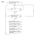
- FIG. 8 shows details of the screen during assay which is displayed on the display of the data processing unit of the gene amplification detection device shown in FIG. 1 ;
- FIG. 9 is a flow chart illustrating the scheduling process by the data processing unit of the gene amplification detection device shown in FIG. 1 ;
- the present embodiment is described in terms of a gene amplification detection device.
- the gene amplification detection device is an analyzer aiding the diagnosis of cancer metastasis in surgically excised tissue; nucleic acids (mRNA) of cancerous origin present in the excised tissue are amplified using the LAMP (loop-mediated isothermal amplification) method, and the marker gene is detected by measuring the turbidity of the liquid generated in conjunction with the nucleic acid amplification. Details of the LAMP method are disclosed in U.S. Pat. No. 6,410,278.
- the gene amplification detection device 100 includes an assay unit 101 , and a data processing unit 102 connected to the assay unit 101 by a communication line.
- the assay unit 101 includes a controller 80 which is provided with a CPU 80 a and memory 80 b , as shown in FIGS. 1 and 2 .
- the controller 80 controls the operation of the assay unit 101 , and controls the input and output between the assay unit 101 and external devices.
- the data processing unit 102 is a personal computer including a keyboard 102 a , mouse 102 b , display 102 c , and controller 102 d , as shown in FIG. 1 .
- the controller 102 d includes memories such as ROM and RAM and the like, and a CPU.
- the assay unit 101 includes a dispensing mechanism 10 , sample container holder 20 , reagent container holder 30 , tip holder 40 , tip disposal unit 50 , container holder 60 including five reaction detection blocks 60 a , a cover closing mechanism 63 , and a transfer unit 70 for moving the dispensing mechanism 10 in the X- and Y-axis directions.
- the assay unit 101 has an internal power source 90 for supplying power to the entire device including the controller 80 .
- An emergency stop switch 91 is provided at a predetermined location on the front of the assay unit 101 .
- the dispensing mechanism 10 includes an arm 11 which is moved in the X-axis and Y-axis directions (horizontal directions) by the transfer unit 70 , and two syringe units 12 which are respectively movable in the Z-axis direction (vertical direction) independent of the arm 11 .
- a sample container placement platform 21 which is provided with five sample container holes 21 a and a handle 21 b , is removably inserted in a concavity (not shown in the drawing) of the sample container holder 20 .
- a microswitch 21 c is assembled at the bottom of each of the five sample container holes 21 a .
- the five microswitches 21 c are OFF when a sample container 22 is not placed in the sample container hole 21 a , and are ON when a sample container is placed in the sample container hole.
- the five microswitches 21 c are respectively connected to the controller 80 .
- the five sample container holes 21 a are sequentially arranged from the inner side of the device as following: sample position 1 , sample position 2 , sample position 3 , sample position 4 , and sample position 5 .
- Sample containers 22 which contain soluble extract (sample) prepared processing excised tissue (homogenizing, filtering, diluting) beforehand are placed in the five sample container holes 21 a of the sample container placement platform 21 .
- samples 22 which contain soluble extract (sample) prepared processing excised tissue (homogenizing, filtering, diluting) beforehand are placed in the five sample container holes 21 a of the sample container placement platform 21 .
- In the sample container holes 21 a are also placed containers which contain a negative control for confirming normal non-amplification of genes which should not be amplified, and a positive control for confirming normal amplification of genes which should be amplified.
- a reagent container placement platform 31 which includes two primer container holes 31 a and one enzyme container hole 31 b and a handle 31 c , is removably inserted in a concavity (not shown in the drawing) of the reagent container holder 30 .
- the primer reagent container holes 31 a of the reagent container placement platform 31 are arranged along the Y-axis direction at predetermined spacing, and the enzyme reagent container hole 31 b is provided only on the front left side.
- Primer reagent containers 32 a containing cytokeratin 19 (CK19) and enzyme reagent container 32 b containing both CH19 and ⁇ -actin are respectively placed in the primer reagent container hole 31 a and enzyme reagent container hole 32 b on the front left side.
- a primer reagent container 32 containing ⁇ -actin primer reagent is placed in the primer reagent container hole 31 a on the front right side.
- Two racks 42 which are provided with holes 42 a for accommodating 36 pipette tips 41 , are removably inserted in two concavities (not shown in the drawing) of the tip holder 40 .
- Two detachment buttons 43 are provided on the tip holder 40 .
- the racks 42 are put in a removable state by depressing the detachment buttons 43 .
- tip disposal holes 50 a for disposing of used pipette tips 41 are provided in the tip disposal unit 50 .
- a channel 50 b having a width narrower than the tip disposal holes 50 a is provided to connect the tip disposal holes 50 a.
- the five reaction detection blocks 60 a of the container holder 60 respectively include reaction unit 61 and two turbidity detection units 62 , as shown in FIG. 2 .
- Two detection cell placement positions 61 a for placing the transparent detection cell 65 are provided in each reaction unit 61 , as shown in FIG. 3 .
- the detection cell 65 is a container for reacting sample and reagent.
- the detection cell 65 has two container parts for containing the sample and the reagent. Each container part is accommodated in the cell placement position 61 a . A hole for accommodating the container part is provided in the detection cell placement position 61 a .
- Each reaction detection block 60 a is arranged sequentially from the inner side of the device as follows: cell position 1 , cell position 2 , cell position 3 , cell position 4 , cell position 5 .
- the turbidity detection unit 62 includes an LED light source 62 a which is a blue color LED having a 465 nm wavelength and which mounted on a base plate 64 a positioned on one side wall of the reaction unit 61 , and a photodiode photoreceptor 62 b mounted on a base plate 64 b positioned on another side wall of the reaction unit 61 .
- a set of turbidity detection units 62 which include one LED light source 62 a and one photodiode photoreceptor 62 b , are arranged in pairs in each reaction detection block 60 a .
- a total of ten sets of turbidity detection units 62 which include LED light source 62 a and photodiode photoreceptor 62 b , are arranged in the five reaction detection blocks 60 a .
- the LED light source 62 and its corresponding photodiode photoreceptor 62 b are arranged such that the photodiode photoreceptor 62 b is capable of receiving the approximately 1 mm diameter light beam emitted from the LED light source 62 a at the bottom of the detection cell 65 .
- the controller 80 determines whether or not a detection cell 65 is present based on the intensity of the light received by the photodiode photoreceptor 52 b .
- the light received by the photodiode photoreceptor 62 b is attenuated when a detection cell 65 is disposed between the LED light source 62 a and the photodiode photoreceptor 62 b than when a detection cell 65 is not present.
- the controller 80 is capable of determining when a detection cell 65 is placed.
- the controller 102 d monitors in real time the turbidity of the liquid contained within the detection cell 65 by means of the intensity of the light received by the photodiode photoreceptor 62 b.
- the transfer unit 70 includes a direct-drive guide 71 and ball screw 72 for moving the dispensing mechanism 10 in the Y-axis direction, stepping motor 73 for driving the ball screw 72 , and direct-drive guide 74 and ball screw 75 for moving the dispensing mechanism 10 in the X-axis direction, and stepping motor 76 for driving the ball screw 76 .
- Moving the dispensing mechanism 10 in the X- and Y-axis directions is accomplished by rotating the ball screws 72 and 75 using the stepping motors 73 and 76 , respectively.
- the operation of the gene amplification detection device 100 of the present embodiment is described below with reference to FIGS. 1 through 8 .
- the gene amplification detection device 100 is a device in which a plurality of detection cells 65 to be used are placed in the reaction detection block 60 a by a user, then the assay operation is started according to the user directions, and when assay operation have been completed for all the placed detection cells 65 , the used detection cells 65 are removed by the user.
- a sample container 22 which contains a soluble extract liquid (sample) prepared beforehand by processing (homogenizing, filtering, diluting) excised tissue, is placed in the sample container hole 21 a of the sample container platform 21 .
- the user places the primer reagent container 32 a containing CK19 (cytokeratin 19) and the enzyme reagent container 32 b containing both CK19 and ⁇ -actin enzyme reagent in the front left side primer reagent container hole 31 a and enzyme reagent container hole 31 b (refer to FIG. 3 ).
- the user places the primer reagent container 32 a containing ⁇ -actin in the front right side primer reagent container hole 31 a and enzyme reagent container hole 51 b.
- assay information relating to the assays of a sample such as assay item, an ID (identification information) for identifying a sample, the number of assays and the like are recorded on the screen of the display 102 c of the data processing unit 102 using the keyboard 102 a and mouse 102 b of the data processing unit 102 shown in FIG. 1 . Details of the recording of assay information are described below with reference to FIGS. 4 through 7 . First, the layout of the screen of the display 102 c of the data processing unit 102 is described referring to FIG. 4 .
- This screen is provided with an order list display 122 for displaying the recording status of the assay information, batch number display 123 , group list display 124 for selecting assay item, cell placement position displays 125 a through 125 e , sample placement position display 126 , and assay start button 127 .
- assay information of the sample placement positions 1 through 5 is input to the order input unit 121 on the screen of the display 102 c in the standby state shown in FIG. 4 .
- the order input unit 121 displays a screen for recording the assay information of the sample placement position indicated by the cursor 122 a .
- the ID for identifying the sample is input using the keyboard 102 a .
- ID representing negative control and positive control and the like may be entered as this ID.
- the biological material ID may be, for example, “sample 001 ⁇ sample 005”; negative control ID may be “Neg”; and positive control ID may be “Pos.”
- the example shown in FIG. 4 shows all input IDs are biological material IDs.
- Comments are input in the comment input unit 121 b of the order input unit 121 for each sample.
- the number of assays for a single sample is selected from a pull-down menu 121 c of the order input unit 121 .
- [1] or [2] can be set as the number of assays; [1] is set as the number of assays for sample 004 in the example of FIG. 4 .
- the enter key is pressed on the keyboard 102 a
- the input ID and number of assays are stored in the memory of the controller 102 d , and displayed on the order list display 122 .
- the sample placement position display 126 displays from the top down sample position 1 , sample position 2 , sample position 3 , sample position 4 , sample position 5 .
- An alphabetical letter (“S” in the present embodiment) corresponding to the top letter of the ID displayed on the order list display 122 is displayed on the sample placement position display 126 .
- FIG. 4 shows a screen of sample placement position 4 after assay information has been input. When “Neg” is input as the ID, “N” is displayed, and when “Pos” is input as the ID, “P” is displayed on the sample placement position display 126 .
- the sample placement position of an input ID is displayed with a green or red background depending on whether or not the sample container 22 is placed in the sample container hole (presence/absence of the sample container).
- the backgrounds of the sample placement positions 1 through 4 are displayed in green or red. Accordingly, the position of the sample container hole 21 a in which the sample container 22 is to be placed, and whether or not the sample container 22 is actually placed at this position can be confirmed by the user looking at the sample placement position display 126 .
- the sample placement positions for which IDs are not input are displayed with a white background.
- the number of the batch process is automatically displayed on the batch number display 123 .
- the batch process is for performing the processing of a plurality of samples in a batch. That is, in a single batch process, the gene amplification detection device 100 starts the assay operation according to the user directions after the user has placed the plurality of detection cells 65 to be used in the reaction detection blocks 60 a , and ends the assay operation for all the placed detection cells 65 .
- a group is selected from the pull-down menu 124 a . Selections for this group include group (B-CK) for assaying two assay item CK19 and ⁇ -actin, group (CK) for assaying only CK19, group (B) for assaying only ⁇ -actin, and group (Other) for assaying three assay item by adding one other assay item to the CK-a9 and ⁇ -actin.
- FIG. 4 shows an example when group (B-CK) is selected for assaying two item of CK19 and ⁇ -actin.
- the assay item CK19 and ⁇ -actin specified for the sample which has its ID displayed on the order list display 122 , is stored in the memory 102 e , and a [O] symbol is displayed in the locations corresponding to CK19 and ⁇ -actin on the order list display 122 .
- the cell placement position displays 125 a through 125 e show the status of the five reaction detection blocks 60 a graphically.
- the cell placement position displays 125 a through 125 e correspond to the cell placement positions 1 through 5 of the reaction detection blocks 60 a of the assay unit 101 the position of the reaction detection block 60 a in which the detection cells 65 are to be placed, and whether or not the detection cells 65 are actually placed at these positions can be confirmed by the user glancing at the cell placement position displays 125 a through 125 e.
- the processes performed by the data processing unit 102 and assay unit 101 in conjunction with the input assay information on the order input unit 121 is described below with reference to FIGS. 5 through 7 .
- Processing in the data processing unit 102 is performed by the controller 102 d
- processing in the assay unit 101 is performed by the controller 80 .
- the cell placement status request transmission process executed by the controller 102 d of the data processing unit 102 is described with reference to FIG. 5 .
- step S 2 a determination is made as to whether or not assay information has been input to the order input unit 121 , that is, whether or not there is ID information and the like input via the ID input unit 121 a and input from the enter key of the keyboard 102 a .
- step S 3 a process is executed to acquire the top letter of the ID input in the ID input unit 121 a .
- step S 4 the display of the sample placement position is updated on the sample placement display 126 based on the acquired top letter.
- the letter [S] is updated at sample placement positions 1 through 4 on the sample placement position display 126 in correspondence with the sample 001 through sample 004.
- the background of the sample placement position display 126 is white in step S 4 based on the sample placement position input in step S 2 .
- step S 5 the number (1 trough 3) of assay item corresponding to the set group is stored in the memory of the controller 102 d . Since the two assay item CK19 and ⁇ -actin are set in group (B-CK) in the example of FIG. 4 , [2] is stored in memory as the assay item number.
- step S 6 the total number of assays is calculated and stored in memory. The total number of assays is calculated by totaling the number of assays set using the pull-down menu 121 c for the respective samples.
- step S 7 a determination is made as to whether or not the timer has timed out.
- step S 8 data (cell placement status request) requesting acquisition of the placement status of the detection cells 65 and sample containers 22 are transmitted to the assay unit 101 .
- the data requesting acquisition of the placement status sent to the assay unit 101 includes the total number of assays acquired in step S 6 and the number of assay item acquired in step S 5 .
- step S 7 When it is determined that the timer has not timed out in step S 7 , the routine returns to step S 2 . When it is determined that assay information has not been input in step S 2 , the routine advances to step S 7 .
- step S 11 data reception is awaited.
- step S 12 determines whether or not the received data is a cell placement status request.
- step S 13 the number of assay item included in the cell placement status request (acquired in step S 5 ) is obtained, and the total number of assays included in the cell placement status request (calculated in step S 6 ) is obtained.
- step S 15 a schedule is created for the use of the detection cells 65 based on the total number of assays and the number of assay item.
- step S 15 The scheduling process of step S 15 is described below using FIG. 9 .
- step S 31 the presence/absence of the detection cell 65 was obtained for the respective reaction detection blocks 60 a of the cell placement positions 1 through 5 based on the intensity of the light received by the photodiode photoreceptor 62 b , and the information is stored in the memory 80 a .
- the presence/absence of the detection cell 65 is determined by comparing the intensity of the light received by the photodiode photoreceptor 62 b with a predetermined value stored beforehand in the memory 80 b , and determining that a detection cell 65 is placed (detection cell present) when the intensity of the light is less than the predetermined value, and determining that a detection cell is not placed (detection cell absent) when the intensity of the light is equal to or greater than the predetermined value.
- step S 32 the number of required cells is calculated.
- the number of required cells is set at an integer by rounding off the decimal point.
- equation (1) gives 2 ⁇ 4 ⁇ 2, and it is determined that four detection cells 65 including two cells 66 a are required.
- step S 33 [1] is entered in “i” as the initial value.
- step S 34 the gene amplification detection device 100 determines whether or not a previous batch process is being assayed. If the assay is on-going, then in step S 35 , the cell placement position i is determined to be in the [mask] state and is stored in the memory 80 b . Thereafter the process advances to step S 41 .
- step S 36 a determination is made in step S 36 as to whether or not the reaction detection block 60 a at cell placement position i is being used.
- This determination compares “i” with the calculated number of required cells of step S 32 , and when the “i” is greater than the number of required cells, the cell placement position i is determined to be not in use, whereas the cell placement position i is determined to be in use when “i” is equal to or less than the number of required cells.
- step S 37 a determination is made in step S 37 as to whether or not the detection cell 65 is placed in the reaction detection block 60 a of cell placement position i based on the presence/absence of the detection cell 65 in the reaction detection block 60 a of the cell placement position i stored in the memory 80 b in step S 31 .
- step S 41 When it is determined that a detection cell 65 is placed in the reaction detection block 60 a of the cell placement position i, then it is determined that the reaction detection block 60 a of the cell placement position i is a [G] state and stored in the memory 80 b in step S 38 . The process then advances to step S 41 .
- step S 37 When it is determined in step S 37 that a detection cell 65 is not placed in the reaction detection block 60 a of the cell placement position i, it is determined that the reaction detection block 60 a of the cell placement position i is a [NG] state and stored in the memory 80 b in step S 39 . Then the process advances to step S 41 .
- step S 36 When it is determined in step S 36 that the reaction detection block 60 a of the cell placement position i is not being used, it is determined that the reaction detection block 60 a of the cell placement position i is in a [Not Used] state and stored in the memory 80 b . The process advances to step S 41 .
- step S 41 i+1 is entered for “i”.
- step S 42 a determination is made as to whether or not “i” is equal to or less than 5; when “i” is equal to or less than 5, the process returns to step S 34 . When “i” is greater than 5, the scheduling process ends, and the routine moves to the process of step S 16 ( FIG. 6 ).
- [Mask] represents a state in which the cell placement status cannot be determined because a previous batch process is on-going
- [G] represents a state in which both the use of the reaction detection block 60 a of the cell placement position i is scheduled and the detection cell 65 need not be placed because the detection cell 65 is being placed
- [NG] represents a state in which the detection cell 65 must be placed because a detection cell 65 is not placed although the use of the reaction detection block 60 a of the cell placement position i is scheduled
- [Not Used] represents a state in which the detection cell 65 need not be placed because the use of the reaction detection block 60 a of the cell placement position i is not scheduled.
- step S 16 a process (sample container presence/absence) is executed for determining whether or not a sample container 22 is placed in the five sample container holes 21 a .
- a determination is made as to whether or not the five microswitches 21 c are ON; sample containers 22 are determined to be placed in the sample container hole 21 a when the microswitch 21 c is ON.
- step S 17 the cell placement status response is sent to the data processing unit 102 .
- the cell placement status response includes the cell placement status in the reaction detection block 60 a (Mask, G, NG, and Not Used), and information on the presence/absence of the sample containers 22 for the respective sample placement positions of the sample container holes 21 a.
- step S 12 When it is determined in step S 12 that the received data is not a cell placement status request, the process returns to step S 11 .
- step S 21 data reception is awaited.
- step S 22 a determination is made as to whether or not the received data is the cell placement status response.
- step S 23 the status of the reaction detection block 60 a of the respective cell placement positions is obtained.
- step S 24 the presence/absence of the sample containers 22 is obtained for the sample container holes 21 a of the respective sample placement positions.
- step S 25 the cell placement position displays 125 a through 125 e and the sample placement position display 126 are updated based on the data obtained in steps S 23 and S 24 .
- the cell placement position displays 125 a and 125 b display [G] in the example of FIG. 4 , thus there is scheduled use of the detection cells 65 in the reaction detection block 60 a of the cell placement position 1 corresponding to the cell placement position display 125 a and the cell placement position 2 corresponding to the cell placement display 125 b , and, the detection cells 65 need not be placed because the detection cells 65 are being placed at the reaction detection block 60 a of the cell placement position 1 and 2 . Furthermore, the cell placement position displays 125 a and 125 b are displayed in green.
- the detection cells 65 Since the cell placement position displays 125 c and 125 d display [NG], the detection cells 65 must be placed because detection cells have not yet been placed although the use of the reaction detection block 60 a of the cell placement position 3 corresponding to the cell placement position display 125 c and the cell placement position 4 corresponding to the cell placement position display 125 d are scheduled. Furthermore, the cell placement position displays 125 c and 125 d are displayed in red.
- the cell placement position display 125 e Since the cell placement position display 125 e is displayed in gray, there is no need to place the detection cell 65 because there is no scheduled use of the detection cell 65 in the reaction detection block 60 a of the cell placement position 5 corresponding to the cell placement position display 125 e .
- the display of the cell placement position display 125 e in gray indicates the [Not Used] status of the cell placement position 5 .
- step S 25 it is determined that the sample containers 22 are being placed, and the sample placement positions with ID input are displayed with a green background on the sample placement position display 126 .
- step S 22 When the received data is not the cell placement status response in step S 22 , the process returns to step S 21 .
- the user confirms the placement status of the detection cells 65 , and determines whether or not the detection cells 65 must be placed based on the updated display of the cell placement status of the reaction detection blocks 60 a in step S 25 .
- detection cells 65 must be placed at the reaction detection blocks 60 a of the cell placement positions 3 and 4 corresponding to the cell placement positions displays 125 c and 125 d displaying [NG] (red), therefore detection cells 65 are placed in the corresponding reaction detection blocks 60 a (reaction detection blocks 60 a which are third and fourth counting from the inner side of the device).
- step S 15 it is determined that detection cells 65 are being placed in the reaction detection blocks 60 a of the cell placement positions 3 and 4 , and the cell placement status is updated from [NG] to [G]. Then, in step S 17 , the cell placement status response is sent to the data processing unit 102 . Then, the controller 102 d of the data processing unit 102 acquires status of the reaction detection blocks 60 a of the cell placement positions 3 and 4 in step S 23 , and update the displays of the cell placement position displays 125 c and 125 d from [NG] (red) to [G] (green) in step S 25 . In this way the detection cell 65 is properly placed and the start of the assay is enabled.
- the user uses the mouse 102 b to click the assay start tab 127 shown in FIG. 4 .
- the assay operation is started in the assay unit 101 .
- the gene amplification detection device 100 sends an assay start instruction from the data processing unit 102 to the assay unit 101 , and the assay unit 101 starts the assay operation.
- the gene amplification detection device 100 does not start the assay operation even when the user clicks the assay start tab 127 if [NG] or [Mask] is displayed on any of the cell placement displays 125 a through 125 e.
- the data processing unit 102 displays a message instructing that a detection cell 65 should be placed in the reaction detection block 60 a on the display 102 c.
- the arm 11 of the dispensing mechanism 10 is moved in the X-axis direction by the transfer unit 70 above the two primer reagent containers 32 a which contain the CK19 and ⁇ -actin primer reagents and are placed in the reagent container placement platform 31 .
- the tips of the two pipette tips 41 installed in the two syringe units 12 are inserted into the liquid surface of the primer reagents CK19 and ⁇ -actin within the primer reagent containers 32 a by the syringe units 12 by lowering the two syringes 12 .
- the CK19 and ⁇ -actin primer reagent within the primer reagent containers 32 a are suctioned by the syringes 12 .
- the arm 11 of the dispensing mechanism 10 is moved by the transfer unit 70 above the reaction detection block 60 a positioned at the cell placement position 1 on the innermost side (front inner side of the device).
- the two pipette tips 41 installed in the two syringe units 12 are respectively inserted into the two cells 66 a of the detection cell 65 .
- the two primer reagents CK19 and ⁇ -actin are discharged into the two cells 66 a by the syringes 12 .
- the arm 11 of the dispensing mechanism 10 is moved in the X-axis direction above the tip disposal unit 50 by the transfer unit 70 .
- the pipette tips 41 are disposed of in the tip disposal unit 50 . Specifically, the pipette tips 41 are inserted into the two tip disposal holes 50 a (refer to FIG. 3 ) of the tip disposal unit 50 by lowering the two syringes 12 . In this state, the pipette tips 41 are moved to the bottom of the channel 50 b by moving the arm 11 of the dispensing mechanism 10 in the Y-axis direction by the transfer unit 70 .
- the flange on the top surface of the pipette tips 41 contacts the bottom surface of the bilateral sides of the channel 50 b so as to receive a downward force from the bottom surface of the channel 50 b , and the pipette tips 41 are automatically detached from the nozzle of the two syringes 12 . In this way the pipette tips 41 are disposed in the tip disposal unit 50 .
- the arm 11 of the dispensing mechanism 10 is again moved to the tip holder 40 by the transfer unit 70 . Thereafter, at the tip holder 40 , two new pipette tips 41 are automatically installed on the tips of the nozzles of the two syringes by the previously described operation.
- the arm 11 of the dispensing mechanism 10 is moved by the transfer unit 70 in the X-axis direction above the enzyme reagent container 32 b which contains both CK19 and ⁇ -actin reagents and placed in the reagent container placement platform 31 , and thereafter the enzyme reagent within the enzyme reagent container 32 b is suctioned.
- one syringe unit 12 is lowered to a position above the enzyme reagent container 32 b and enzyme reagent is suctioned, and subsequently this syringe unit 12 is lifted. Thereafter, the arm 11 of the dispensing mechanism 10 is moved in the Y-axis direction by the transfer unit 70 so that the other syringe unit 12 is positioned above the same enzyme reagent container 32 b . Then, the other syringe unit 12 is lowered and the enzyme reagent is suctioned from the same enzyme reagent container 32 b , and thereafter the other syringe unit 12 is raised.
- the arm 11 of the dispensing mechanism 10 then is moved above the reaction detection block 60 a on the innermost side by the transfer unit 70 , and the CK19 and ⁇ -actin enzyme reagent is discharged into the two cells 66 a of the detection cell 65 . After the enzyme reagent has been discharged, the arm 11 of the dispensing mechanism 10 is moved above the tip disposal unit 50 by the transfer unit 70 , and the pipette tips 41 are disposed.
- the arm 11 of the dispensing mechanism 10 is again moved to the tip holder 40 by the transfer unit 70 , and subsequently two new pipette tips 41 are automatically installed on the tips of the nozzles of the two syringe units 12 . Then, the arm 11 of the dispensing mechanism 10 is moved by the transfer unit 70 in the X-axis direction above the sample container 22 which contains a sample and is placed in the sample container placement platform 21 , and subsequently the sample in the sample container 22 is suctioned by the same operation as the enzyme reagent suction operation.
- the arm 11 of the dispensing mechanism 10 is moved by the transfer unit 70 above the reaction detection block 60 a on the innermost side, and subsequently the two syringe units 12 are lowered and identical samples are discharged into the two cells 66 a of the detection cell 65 .
- the temperature of the liquid in the detection cell 65 is maintained at approximately 20° C.
- the arm 11 of the dispensing mechanism 10 is moved above the tip disposal unit 50 by the transfer unit 70 , and the pipette tips 41 are disposed.
- the cover-closing operation of the cover 67 a of the detection cell 65 is performed.
- the temperature of the liquid in the cell 66 a is increased from approximately 20° C. to approximately 65° C. to amplify the nucleic acid (mRNA) via the LAMP (gene amplification) reaction.
- the target gene is detected using a nephelometric method to analyze the turbidity, which is produced by magnesium pyrophosphate generated in conjunction with amplification of the nucleic acid.
- the controller 102 d monitors the turbidity of the liquid contained in the detection cell 65 in real time by means of the intensity of the light received by the photodiode photoreceptor 62 b shown in FIG. 3 .
- the target gene is detected by the reaction detection block 60 a positioned on the innermost side.
- the reaction detection blocks 60 a second through fourth from the inner side may sequentially perform similar operations of target gene detection to that performed by the reaction detection block 60 a on the innermost side.
- the detection operation ends when the target gene detection operation performed by the fourth reaction detection block 60 a ends. Thereafter, the user grips the handle 67 c of the detection cell 65 and disposes of the four detection cells 65 .
- the [Mask] state is determined in which the status of the cell placement position cannot be determined in step S 35 .
- the cell placement position displays 125 a through 125 e of the display 102 c show Mask 128 a ⁇ 128 e , as shown in FIG. 8 . It is possible to input assay information for the current batch process even during an on-going assay of a previous batch process, as shown in the screen of FIG. 8 .
- the IDs “Sample 005” and “Sample006” and the number of assays for one cycle are input, and the B-CK group is selected for assaying the two item of CK19 and ⁇ -actin.
- the user can easily confirm the placement position of the detection cells 65 since the placement positions required for the placement of the detection cells 65 of the container holder 60 are displayed on the display 102 c by providing the controllers 80 and 102 d for acquiring the status of the detection reaction blocks 60 a based on the assay information input through the keyboard 102 a and mouse 102 b and output of the photodiode photoreceptor 62 b , and by providing the display 102 c for displaying the status of the reaction detection block 60 a acquired by the controllers 80 and 102 d .
- a detection cell 65 is actually placed at the specified cell placement position of the reaction detection block 60 a can be detected by providing the LED light source 62 a and photodiode photoreceptor 62 b for detecting whether or not a detection cell 65 is placed in the reaction detection block 60 a , the user can determine when a detection cell 65 is placed in the proper cell placement position of the reaction detection block 60 a.
- the user can easily confirm the placement status of the reaction detection blocks 60 a since colors corresponding to the detection cell 65 placement status (green for [G], red for [NG], and gray for [Not Used]) are displayed in addition to the abbreviations ([G], [NG]) indicating the detection cell 65 placement status on the cell placement position displays 125 a through 125 e.
- the detection block has a simplified structure compared to separate detection block for detecting the presence/absence of the detection cell 65 , and detecting the turbidity of the liquid contained in the detection cell 65 since the presence/absence of the detection cell 65 and the turbidity of the liquid contained in the detection cell 65 can be detected using a single turbidity detection unit 62 having an LED light source 62 a and photodiode photoreceptor 62 b.
- the controller 80 of the assay unit 101 determines the presence/absence of the detection cell 65 based on the light received by the photodiode photoreceptor 62 b
- the controller 102 of the data processing unit 102 analyzes the turbidity if the liquid in the detection cell 65 based on the light received by the photodiode photoreceptor 62 b , and processing speed is improved since processing is performed by the two controllers 80 and 102 d.
- the analyzer of the present invention is described by way of example applied to a gene amplification detection device for amplifying a target nucleic acid using the LAMP method in the above embodiment, the present invention is not limited to this arrangement inasmuch as the present invention may also be applied to gene amplification detection devices (nucleic acid detection devices) for amplifying a target nucleic acid using a polymerase chain reaction (PCR method) and ligase chain reaction (LCR method). Furthermore, the present invention is broadly applicable to analyzers other than gene amplification detection devices.
- the present embodiment has been described by way of example of detecting the presence/absence of a detection cell 65 and detecting the turbidity of the liquid contained in the detection cell using a single turbidity detection unit 62 having a LED light source 62 a and photodiode photoreceptor 62 b , the present invention is not limited to this arrangement inasmuch as the detection of the presence/absence of the detection cell 65 also may be detected based on the intensity of light obtained from a separate detection unit than the detection of the turbidity of the liquid contained in the detection cell 65 .
- letters representing an abbreviation ([G], [NG]) indicating the placement status of a reaction detection block 60 a , and colors corresponding to the detection cell 65 placement status (green for [G], red for [NG], and gray for [Not Used]) are displayed on the cell placement position displays 125 a through 125 e , however, the present invention is not limited to this arrangement inasmuch as only one may be displayed among the abbreviations and patterns representing the placement status of the reaction detection blocks 60 a , and colors corresponding to the placement status of the reaction detection blocks 60 a .
- the presence/absence of a detection cell 65 is determined by the controller 80 , and the analysis of the turbidity of the liquid in the detection cell 65 is determined by the controller 102 d , however, these determinations also may be made by one controller.
- the placement status of the sample container in the sample container placement hole 21 a , and the placement status of the detection cell 65 in the reaction detection block 60 a are displayed on the display 102 c , however, the present invention is not limited to this arrangement inasmuch as the placement status of the reagent containers in the primer reagent container hole 31 a and the enzyme reagent container hole 31 b also may be displayed on the display 102 c.
- the presence/absence of the detection cell 65 is accomplished using a turbidity detection unit 62 including an LED light source 62 a and photodiode photoreceptor 62 b , however, the present invention is not limited to this arrangement inasmuch as the presence/absence of the detection cell 65 also may be detected by providing a microswitch within the hole of the detection cell placement position 61 a and having the microswitch turn ON when a detection cell 65 is placed therein.
- the assay operation is started when the user clicks the assay start tab 127
- the present invention is not limited to this arrangement inasmuch as an assay start switch may be provided on the assay unit 101 to start the assay operation when the user presses this start switch.
- the reaction unit 61 is disposed between the LED light source 62 a and the photodiode photoreceptor 62 b , and the controller 80 determines the presence/absence of the detection cell 65 based on the intensity of the light received by the photodiode photoreceptor 62 b , however, the present invention is not limited to this arrangement inasmuch as the LED light source 62 a and photodiode photoreceptor 62 b may be provided on one side wall of the reaction unit 61 and the controller 80 may determine the presence/absence of the detection cell 65 based on the intensity of the light received by the photodiode photoreceptor 62 b .
- the controller 80 may compare the light received by the photodiode photoreceptor 62 b with a predetermined value stored beforehand in the memory 80 b , and determines the presence of the detection cell 65 when the light intensity is greater than the predetermined value, and determine the absence of the detection cell 65 when the light intensity is less than the predetermined value.
- the present invention is not limited to this arrangement inasmuch as only the sample placement positions for which an ID has been input may be displayed on the sample position display 126 , and only the cell placement position of scheduled use may be displayed on the cell placement position displays 125 a through 125 e.
- the detection cell 65 has the two container parts, however, the present invention is not limited to this arrangement inasmuch as the detection cell 65 may have single container part.
- the reaction detection block 60 a has two detection cell placement positions 61 a
- the present invention is not limited to this arrangement inasmuch as the reaction detection block 60 a may have single detection cell placement positions 61 a.
Landscapes
- Engineering & Computer Science (AREA)
- Robotics (AREA)
- Physics & Mathematics (AREA)
- Health & Medical Sciences (AREA)
- Life Sciences & Earth Sciences (AREA)
- Chemical & Material Sciences (AREA)
- Analytical Chemistry (AREA)
- Biochemistry (AREA)
- General Health & Medical Sciences (AREA)
- General Physics & Mathematics (AREA)
- Immunology (AREA)
- Pathology (AREA)
- Apparatus Associated With Microorganisms And Enzymes (AREA)
- Automatic Analysis And Handling Materials Therefor (AREA)
Abstract
Description
Number of required cells={(number of assay item)×(total number of assays)−(number of assay item unchecked on the
Claims (8)
Applications Claiming Priority (2)
| Application Number | Priority Date | Filing Date | Title |
|---|---|---|---|
| JP2004-012014 | 2004-01-20 | ||
| JP2004012014A JP4505230B2 (en) | 2004-01-20 | 2004-01-20 | Analysis equipment |
Publications (2)
| Publication Number | Publication Date |
|---|---|
| US20050175504A1 US20050175504A1 (en) | 2005-08-11 |
| US8663557B2 true US8663557B2 (en) | 2014-03-04 |
Family
ID=34823676
Family Applications (1)
| Application Number | Title | Priority Date | Filing Date |
|---|---|---|---|
| US11/038,951 Expired - Fee Related US8663557B2 (en) | 2004-01-20 | 2005-01-19 | Analyzer |
Country Status (2)
| Country | Link |
|---|---|
| US (1) | US8663557B2 (en) |
| JP (1) | JP4505230B2 (en) |
Cited By (2)
| Publication number | Priority date | Publication date | Assignee | Title |
|---|---|---|---|---|
| US10338086B2 (en) | 2016-06-06 | 2019-07-02 | Roche Diagnostics Operations, Inc. | Supplying consumable items to an automated sample analyzer |
| US11079401B2 (en) | 2016-03-09 | 2021-08-03 | 9106634 Canada Ltd. | Apparatus and method for indicating at least one property related to an object |
Families Citing this family (15)
| Publication number | Priority date | Publication date | Assignee | Title |
|---|---|---|---|---|
| JP4766969B2 (en) * | 2005-09-14 | 2011-09-07 | シスメックス株式会社 | Organization property judgment device |
| JP4961771B2 (en) * | 2006-02-23 | 2012-06-27 | 東亜ディーケーケー株式会社 | Autosampler and analysis system |
| JP4825548B2 (en) * | 2006-02-28 | 2011-11-30 | シスメックス株式会社 | Sample analyzer |
| JP4854380B2 (en) * | 2006-05-09 | 2012-01-18 | キヤノン株式会社 | Nucleic acid automatic testing equipment |
| JP2008017832A (en) * | 2006-06-13 | 2008-01-31 | Sysmex Corp | Method for judging metastasis of cancer and device for the same |
| JP4943074B2 (en) * | 2006-07-03 | 2012-05-30 | シスメックス株式会社 | Method and apparatus for determining cancer metastasis |
| JP5405378B2 (en) * | 2010-04-09 | 2014-02-05 | 株式会社日立ハイテクノロジーズ | Nucleic acid analyzer and method |
| US8900527B2 (en) * | 2010-06-29 | 2014-12-02 | Roche Molecular Systems Inc. | Pipetting device with independently movable pipette units |
| WO2013060482A1 (en) * | 2011-10-28 | 2013-05-02 | Torsten Matthias | Device and method for detecting substances present in biological or chemical samples |
| JP5993737B2 (en) * | 2012-12-17 | 2016-09-14 | 株式会社日立ハイテクノロジーズ | Automatic analyzer |
| WO2015136608A1 (en) * | 2014-03-10 | 2015-09-17 | 株式会社島津製作所 | Device for displaying sample status in automatic analyzer, automatic analyzer, and sample status display method |
| JP6904131B2 (en) * | 2017-07-21 | 2021-07-14 | 株式会社島津製作所 | Gene measuring device |
| CN111201440B (en) * | 2017-10-10 | 2021-04-20 | 株式会社日立高新技术 | Automatic analyzer |
| JP7061471B2 (en) | 2018-01-26 | 2022-04-28 | シスメックス株式会社 | Nucleic acid analyzer |
| US12313643B2 (en) * | 2019-05-28 | 2025-05-27 | Roche Diagnostics Operations, Inc. | Reagent drawer and associated detector mounted to a slider capable of extending from an automatic analyzer housing |
Citations (17)
| Publication number | Priority date | Publication date | Assignee | Title |
|---|---|---|---|---|
| US4451433A (en) * | 1980-11-10 | 1984-05-29 | Hitachi, Ltd. | Automatic chemical analyzer |
| US4522921A (en) * | 1981-12-11 | 1985-06-11 | Olympus Optical Co., Ltd. | Sample delivering method for use in automatic chemical analysis |
| JPH0585491A (en) | 1991-02-20 | 1993-04-06 | Japan Airlines Co Ltd | Seat occupation monitoring system |
| US5415840A (en) * | 1992-10-19 | 1995-05-16 | Hitachi, Ltd. | Liquid sample automatic analyzer |
| JPH08262034A (en) | 1995-03-17 | 1996-10-11 | Hitachi Ltd | Automatic analyzer |
| JPH0972911A (en) | 1995-09-04 | 1997-03-18 | Jeol Ltd | User interface of chemical analyzer |
| JPH1019776A (en) | 1996-07-01 | 1998-01-23 | Aloka Co Ltd | Absorbance measuring apparatus and dispenser with absorbance measuring apparatus |
| US6060022A (en) * | 1996-07-05 | 2000-05-09 | Beckman Coulter, Inc. | Automated sample processing system including automatic centrifuge device |
| US6136274A (en) * | 1996-10-07 | 2000-10-24 | Irori | Matrices with memories in automated drug discovery and units therefor |
| JP2000356575A (en) | 1999-06-14 | 2000-12-26 | Sysmex Corp | Liquid sample analyzer |
| US6410278B1 (en) | 1998-11-09 | 2002-06-25 | Eiken Kagaku Kabushiki Kaisha | Process for synthesizing nucleic acid |
| US6709634B1 (en) | 1999-05-11 | 2004-03-23 | Sysmex Corporation | Automatic analytical instrument |
| US20050014285A1 (en) * | 2003-07-18 | 2005-01-20 | Miller David Jeffrey | Method for resupplying reagents in an automatic clinical analyzer |
| US20050013735A1 (en) * | 2003-07-18 | 2005-01-20 | Gebrian Peter Louis | Random access reagent delivery system for use in an automatic clinical analyzer |
| US20050123445A1 (en) * | 2003-07-18 | 2005-06-09 | Lawrence Blecka | System and method for multi-analyte detection |
| US20050186113A1 (en) * | 2004-02-23 | 2005-08-25 | Sysmex Corporation | Analyzer |
| US20060000296A1 (en) * | 2004-07-02 | 2006-01-05 | Salter Jason P | Synchronization of sample and data collection |
Family Cites Families (9)
| Publication number | Priority date | Publication date | Assignee | Title |
|---|---|---|---|---|
| JPH03255960A (en) * | 1990-03-07 | 1991-11-14 | Hitachi Ltd | Automatic analyzer |
| JP2558738Y2 (en) * | 1993-02-26 | 1998-01-14 | 株式会社堀場製作所 | Sample analyzer for electrolyte analyzer |
| JPH06265556A (en) * | 1993-03-15 | 1994-09-22 | Hitachi Ltd | Automatic analyzer |
| JPH1183863A (en) * | 1997-09-11 | 1999-03-26 | Hitachi Ltd | Sample process monitor |
| JPH11316235A (en) * | 1998-05-02 | 1999-11-16 | Shimadzu Corp | Automatic analyzer |
| JP2000336098A (en) * | 1999-05-28 | 2000-12-05 | Hitachi Ltd | Nucleic acid purification equipment |
| JP4446592B2 (en) * | 2000-12-25 | 2010-04-07 | シスメックス株式会社 | Liquid sample measurement unit and automatic liquid sample analyzer equipped with the same |
| JP2003050242A (en) * | 2001-08-08 | 2003-02-21 | Hitachi Ltd | Biological sample processing equipment |
| JP2003329691A (en) * | 2002-05-14 | 2003-11-19 | Fuji Photo Film Co Ltd | Biochemical analyzer |
-
2004
- 2004-01-20 JP JP2004012014A patent/JP4505230B2/en not_active Expired - Lifetime
-
2005
- 2005-01-19 US US11/038,951 patent/US8663557B2/en not_active Expired - Fee Related
Patent Citations (17)
| Publication number | Priority date | Publication date | Assignee | Title |
|---|---|---|---|---|
| US4451433A (en) * | 1980-11-10 | 1984-05-29 | Hitachi, Ltd. | Automatic chemical analyzer |
| US4522921A (en) * | 1981-12-11 | 1985-06-11 | Olympus Optical Co., Ltd. | Sample delivering method for use in automatic chemical analysis |
| JPH0585491A (en) | 1991-02-20 | 1993-04-06 | Japan Airlines Co Ltd | Seat occupation monitoring system |
| US5415840A (en) * | 1992-10-19 | 1995-05-16 | Hitachi, Ltd. | Liquid sample automatic analyzer |
| JPH08262034A (en) | 1995-03-17 | 1996-10-11 | Hitachi Ltd | Automatic analyzer |
| JPH0972911A (en) | 1995-09-04 | 1997-03-18 | Jeol Ltd | User interface of chemical analyzer |
| JPH1019776A (en) | 1996-07-01 | 1998-01-23 | Aloka Co Ltd | Absorbance measuring apparatus and dispenser with absorbance measuring apparatus |
| US6060022A (en) * | 1996-07-05 | 2000-05-09 | Beckman Coulter, Inc. | Automated sample processing system including automatic centrifuge device |
| US6136274A (en) * | 1996-10-07 | 2000-10-24 | Irori | Matrices with memories in automated drug discovery and units therefor |
| US6410278B1 (en) | 1998-11-09 | 2002-06-25 | Eiken Kagaku Kabushiki Kaisha | Process for synthesizing nucleic acid |
| US6709634B1 (en) | 1999-05-11 | 2004-03-23 | Sysmex Corporation | Automatic analytical instrument |
| JP2000356575A (en) | 1999-06-14 | 2000-12-26 | Sysmex Corp | Liquid sample analyzer |
| US20050014285A1 (en) * | 2003-07-18 | 2005-01-20 | Miller David Jeffrey | Method for resupplying reagents in an automatic clinical analyzer |
| US20050013735A1 (en) * | 2003-07-18 | 2005-01-20 | Gebrian Peter Louis | Random access reagent delivery system for use in an automatic clinical analyzer |
| US20050123445A1 (en) * | 2003-07-18 | 2005-06-09 | Lawrence Blecka | System and method for multi-analyte detection |
| US20050186113A1 (en) * | 2004-02-23 | 2005-08-25 | Sysmex Corporation | Analyzer |
| US20060000296A1 (en) * | 2004-07-02 | 2006-01-05 | Salter Jason P | Synchronization of sample and data collection |
Cited By (2)
| Publication number | Priority date | Publication date | Assignee | Title |
|---|---|---|---|---|
| US11079401B2 (en) | 2016-03-09 | 2021-08-03 | 9106634 Canada Ltd. | Apparatus and method for indicating at least one property related to an object |
| US10338086B2 (en) | 2016-06-06 | 2019-07-02 | Roche Diagnostics Operations, Inc. | Supplying consumable items to an automated sample analyzer |
Also Published As
| Publication number | Publication date |
|---|---|
| JP2005207767A (en) | 2005-08-04 |
| JP4505230B2 (en) | 2010-07-21 |
| US20050175504A1 (en) | 2005-08-11 |
Similar Documents
| Publication | Publication Date | Title |
|---|---|---|
| US8663557B2 (en) | Analyzer | |
| US9377383B2 (en) | Specimen processing apparatus | |
| JP5210800B2 (en) | Sample analyzer, reagent information display method and computer program in sample analyzer | |
| EP2040081B1 (en) | Sample analyzer and error information displaying method | |
| JP5372460B2 (en) | Specimen processing system and specimen transport method | |
| JP5170737B2 (en) | Sample analyzer | |
| CN101275965B (en) | Sample analyzer, reagent aspirating method | |
| JP5372551B2 (en) | Sample processing system and sample information display device | |
| JP5339853B2 (en) | Sample processing system | |
| US20100111767A1 (en) | Specimen processing system and specimen container classifying apparatus | |
| JP5220557B2 (en) | Sample processing system and sample container sorting apparatus | |
| US20070183926A1 (en) | Sample measuring apparatus | |
| US20080206098A1 (en) | Sample processing apparatus and sample processing system | |
| JP2010101851A (en) | Sample analysis device | |
| CN111257576B (en) | Sample analysis device and sample analysis method | |
| US20150093754A1 (en) | Analyzer, analyzing method, and tip container | |
| JP5814919B2 (en) | Sample analyzer | |
| JP5331916B2 (en) | Sample analyzer | |
| JP4825548B2 (en) | Sample analyzer | |
| EP3745134A1 (en) | Nucleic acid analysis device and nucleic acid extraction device | |
| CN107636469B (en) | Automatic analysis device | |
| CN112130717A (en) | Display device, specimen measurement system, display method, and recording medium | |
| US20070178513A1 (en) | Nucleic acid amplification apparatus and method | |
| JP2020201291A (en) | Specimen analyzer and specimen analysis method | |
| WO2021176561A1 (en) | Detection device, dispensing device, and dispensing method |
Legal Events
| Date | Code | Title | Description |
|---|---|---|---|
| AS | Assignment |
Owner name: SYSMEX CORPORATION, JAPAN Free format text: ASSIGNMENT OF ASSIGNORS INTEREST;ASSIGNORS:TANOSHIMA, EIJI;WAKAMIYA, YUUJI;REEL/FRAME:016068/0722 Effective date: 20050405 |
|
| FEPP | Fee payment procedure |
Free format text: PAYOR NUMBER ASSIGNED (ORIGINAL EVENT CODE: ASPN); ENTITY STATUS OF PATENT OWNER: LARGE ENTITY |
|
| STCF | Information on status: patent grant |
Free format text: PATENTED CASE |
|
| MAFP | Maintenance fee payment |
Free format text: PAYMENT OF MAINTENANCE FEE, 4TH YEAR, LARGE ENTITY (ORIGINAL EVENT CODE: M1551) Year of fee payment: 4 |
|
| MAFP | Maintenance fee payment |
Free format text: PAYMENT OF MAINTENANCE FEE, 8TH YEAR, LARGE ENTITY (ORIGINAL EVENT CODE: M1552); ENTITY STATUS OF PATENT OWNER: LARGE ENTITY Year of fee payment: 8 |
|
| FEPP | Fee payment procedure |
Free format text: MAINTENANCE FEE REMINDER MAILED (ORIGINAL EVENT CODE: REM.); ENTITY STATUS OF PATENT OWNER: LARGE ENTITY |
|
| LAPS | Lapse for failure to pay maintenance fees |
Free format text: PATENT EXPIRED FOR FAILURE TO PAY MAINTENANCE FEES (ORIGINAL EVENT CODE: EXP.); ENTITY STATUS OF PATENT OWNER: LARGE ENTITY |
|
| STCH | Information on status: patent discontinuation |
Free format text: PATENT EXPIRED DUE TO NONPAYMENT OF MAINTENANCE FEES UNDER 37 CFR 1.362 |