US8646381B2 - Oven rack and drip pan assembly - Google Patents
Oven rack and drip pan assembly Download PDFInfo
- Publication number
- US8646381B2 US8646381B2 US11/466,658 US46665806A US8646381B2 US 8646381 B2 US8646381 B2 US 8646381B2 US 46665806 A US46665806 A US 46665806A US 8646381 B2 US8646381 B2 US 8646381B2
- Authority
- US
- United States
- Prior art keywords
- drip pan
- oven rack
- support
- drip
- oven
- Prior art date
- Legal status (The legal status is an assumption and is not a legal conclusion. Google has not performed a legal analysis and makes no representation as to the accuracy of the status listed.)
- Expired - Fee Related, expires
Links
Images


Classifications
-
- F—MECHANICAL ENGINEERING; LIGHTING; HEATING; WEAPONS; BLASTING
- F24—HEATING; RANGES; VENTILATING
- F24C—DOMESTIC STOVES OR RANGES ; DETAILS OF DOMESTIC STOVES OR RANGES, OF GENERAL APPLICATION
- F24C15/00—Details
- F24C15/14—Spillage trays or grooves
-
- F—MECHANICAL ENGINEERING; LIGHTING; HEATING; WEAPONS; BLASTING
- F24—HEATING; RANGES; VENTILATING
- F24C—DOMESTIC STOVES OR RANGES ; DETAILS OF DOMESTIC STOVES OR RANGES, OF GENERAL APPLICATION
- F24C15/00—Details
- F24C15/16—Shelves, racks or trays inside ovens; Supports therefor
Definitions
- the present invention relates to racks for appliances, and more particularly, to a rack and drip pan assembly for an appliance, such as an oven.
- Appliances such as ovens, often have one or more racks generally within the appliance.
- the racks can be useful for the placing of cookware, food, and other items, within the oven.
- the racks can place the cookware generally towards the middle of the oven, and can keep the cookware away from heating elements and the like.
- ovens with multiple racks allow for placement of cookware on a variety of levels within the oven, thereby increasing the total volume of available cooking.
- the racks are often supported by ledges formed along the inner walls of the oven.
- the racks are then movable in and out of the oven on the ledges. This allows the racks to be removed from the oven for cleaning or for other purposes. Often, the racks may be partially removed from the oven so as to allow easier access to items placed on the racks.
- the ledges also facilitate vertical adjustment of the racks within the oven cavity.
- Appliance racks and specifically oven racks, are often of wire form construction. More specifically, an outer wire frame and a support platform, which is constituted by a plurality of fore-to-aft and laterally spaced wires, define a typical oven rack. The wires are generally evenly spaced across the entire rack for use in supporting food items to be cooked.
- an oven rack and drip pan assembly in an appliance, such as an oven.
- the oven rack includes a support platform and a pair of drip pan rails extending downwardly from opposing sides of the support platform.
- the drip pan includes opposing side portions configured to be slidably received within the drip pan rails and a plurality of vented portions provided through a surface of the drip pan. The vented portions are configured to allow heated air to pass therethrough.
- an oven rack and drip pan assembly includes a support platform having a support frame and a plurality of elongated support wires attached to the support frame to form a support surface extending along a substantially horizontal plane.
- a pair of drip pan rails is also provided.
- Each drip pan rail includes: a downwardly extending member from a front portion of the support platform; an inwardly extending member coupled to an end portion of the downwardly extending member; a drip pan support wire coupled to an end portion of the inwardly extending member, the drip pan support wire extending to a rear portion of the oven rack; and a stop member extending between an end of the drip pan support wire and a rear wire of the support platform.
- the drip pan is configured to be slidably supported by the drip pan rails.
- the drip pan includes a plurality of vented portions provided therein, the vented portions being configured to allow heated air to pass therethrough.
- an oven rack and drip pan is provided.
- the oven rack includes means for supporting a drip pan underneath a support platform of the oven rack.
- the drip pan includes means for allowing air to pass through a surface of the drip pan.
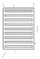
- FIG. 1 illustrates a top view of an oven rack and drip pan assembly in accordance with an aspect of the present invention.
- FIG. 2 illustrates a front view of the oven rack and drip pan assembly of FIG. 1 in accordance with an aspect of the present invention.
- FIG. 3 illustrates a side view of the oven rack and drip pan assembly of FIG. 1 in accordance with an aspect of the present invention.
- FIG. 4 illustrates a bottom perspective view of a drip pan for use with an oven rack in accordance with an aspect of the present invention.
- FIG. 5 illustrates a side view of the drip pan of FIG. 4 in accordance with an aspect of the present invention.
- FIG. 6 illustrates a top view of the drip pan of FIG. 4 in accordance with an aspect of the present invention.
- FIG. 7 illustrates a front view of the drip pan of FIG. 4 in accordance with an aspect of the present invention.
- FIG. 8 illustrates a bottom perspective view of another drip pan for use with an oven rack in accordance with an aspect of the present invention.
- FIG. 9 illustrates a side view of the drip pan of FIG. 8 in accordance with an aspect of the present invention.
- FIG. 10 illustrates a top view of the drip pan of FIG. 8 in accordance with an aspect of the present invention.
- FIG. 11 illustrates a front view of the drip pan of FIG. 8 in accordance with an aspect of the present invention.
- FIG. 12 illustrates a bottom perspective view of yet another drip pan for use with an oven rack in accordance with an aspect of the present invention.
- FIG. 13 illustrates a side view of the drip pan of FIG. 12 in accordance with an aspect of the present invention.
- FIG. 14 illustrates a top view of the drip pan of FIG. 12 in accordance with an aspect of the present invention.
- FIG. 15 illustrates a front view of the drip pan of FIG. 12 in accordance with an aspect of the present invention.
- the present invention relates to a rack for an oven.
- the present invention will now be described with reference to the drawings, wherein like reference numerals are used to refer to like elements throughout. It is to be appreciated that the various drawings are not necessarily drawn to scale from one figure to another nor inside a given figure, and in particular that the size of the components are arbitrarily drawn for facilitating the understanding of the drawings.
- numerous specific details are set forth in order to provide a thorough understanding of the present invention. It may be evident, however, that the present invention can be practiced without these specific details.
- the shown example is not intended to be a limitation on the present invention. For example, one or more aspects of the present invention can be utilized in other embodiments and even other types of racks.
- the assembly 10 includes an oven rack 15 configured to slidably support a drip pan 20 on an underside thereof.
- the oven rack includes a support platform 25 formed by a support frame 30 and a plurality of elongated support wires 35 .
- Both the support frame 30 and support wires 35 can be constructed from metal wire, such as iron coated with nickel or steel coated with porcelain.
- the support frame 30 and support wires 35 can be constructed from various other suitable materials (e.g., various other metals and/or sheet metal).
- the support frame 30 includes a front wire 40 , a rear wire 45 , and opposed side wires 50 , 55 .
- the front wire 40 , rear wire 45 , and side wires 50 , 55 can be attached together to form the support frame 30 in various manners, such as by welding, adhesives, or fasteners, and/or can even be formed from a single piece of wire.
- the front wire 40 , rear wire 45 , and side wires 50 , 55 can include single or multiple elements.
- the support frame 30 can have a generally rectangular geometry; through it is to be appreciated that the support frame 30 can have any other suitable geometry.
- the plurality of elongated support wires 35 can be attached to the support frame 30 .
- the elongated support wires 35 can be welded, or otherwise secured, to the support frame 30 .
- the elongated support wires 35 can extend between any of the front, rear, or side wires 40 , 45 , 50 , 55 and can be oriented at various angles relative to the support frame 30 .
- the elongated support wires 35 can be manufactured from metal wire or various other suitable materials, coated or uncoated, that provide adequate strength to support various items such as cake pans, baking stones, casseroles, or the like, and can withstand the heat of an oven.
- the elongated support wires 35 can form the support surface 25 extending along a substantially horizontal plane so as to provide an area configured to support various items, such as cake pans, cookie sheets, casseroles, and other suitable cookware.
- the oven rack 15 can also include at least one cross member 57 .
- the cross member 57 can be oriented at various angles relative to the elongated support wires 35 . In one example, the cross member 57 can be oriented transverse to the support wires 35 . Additionally, the cross member 57 can be attached to support frame 30 and/or the support wires 35 in various manners, including adhesives, fasteners, or welding, and/or can even be formed with either or both of the support frame 30 or support wires 35 .
- the cross member 57 can also operate to mitigate sagging of the support platform 25 with respect to the support frame 30 when heavy food, cookware, or the like (not shown) is placed on the support platform 25 .
- the cross member 57 can include various materials and/or geometries, such as a larger diameter wire.
- the oven rack 15 further includes a pair of drip pan rails 60 extending downwardly from opposing sides of the support platform 25 .
- Each of the drip pan rails 60 includes at least one downwardly extending member 65 from a front portion of the support platform 25 .
- downwardly extending member 65 can extend from the front wire 40 or from a front portion of one of the support wires 35 .
- the downwardly extending member 65 can extend from one of the side wires 50 , 55 .
- An inwardly extending member 70 extends from an end portion of the downwardly extending member 70 towards a center portion of the rack 15 and is substantially parallel with the front wire 40 of the support frame 30 .
- At least one drip pan support wire 75 extends toward the rear portion of the oven rack 15 in a manner that is substantially parallel with the elongated support wires 35 .
- a stop member 80 extends from a rear end portion of the drip pan support wire 75 to the rear wire 45 . The stop member 80 prevents the drip pan 20 from being pushed beyond the rear portion of the oven rack 15 .
- This configuration of the drip pan rails 60 allows the drip pan 20 to be slidably supported underneath the oven rack 15 .
- a flange or lip portion 85 of the drip pan 20 is configured to slidably engage the drip pan support wires 75 .
- the lip portion 85 can extend around the entire periphery of the drip pan 20 or alternatively, the lip portion 85 can only be provided along opposing side portions of the drip pan 20 for engagement with the drip pan support wires 75 .
- Each of the drip pan rails 60 and its components can be attached to the support frame 30 using one or more various methods, such as by welding, adhesives, or fasteners, and/or can even be formed from a single piece of wire.
- each of the drip pan rails 60 can be formed with the support frame 30 .
- the drip pan rails 60 can be formed of metal wire, such as iron coated with nickel or steel coated with porcelain, or of various other suitable materials that provide adequate strength to support the drip pan 20 and that can withstand the heat of an oven.
- the drip pan 20 is illustrated in greater detail in accordance with an aspect of the invention.
- the drip pan 20 is configured to catch food particles, liquids and other food-related or other matter that may exit a food item or cooking or other vessel placed on the oven rack 15 .
- the drip pan 20 collects such matter for easy clean up and to prevent such matter from entering the interior of the range. Accordingly, using the drip pan 20 can reduce the frequency of cleaning for an oven. However, because the drip pan 20 is supported under the oven rack 15 , heat, which normally reaches the bottom of the cookware and/or food items is blocked by the structure of the drip pan 20 .
- the drip pan 20 of the present invention includes a plurality of vented portions therein for allowing heat to pass through the drip pan 20 .
- the drip pan 20 can include a plurality of louvers 90 formed in a bottom surface 95 of the pan 20 .
- FIG. 1 four substantially parallel rows of eight louvers 90 are provided.
- the louvers 90 are configured to allow heat to pass from a bottom portion of the drip pan 20 through the louvers 90 and to a bottom portion of the cookware or food item that is supported on the support platform 25 of the oven rack 15 .
- the louvers 90 are configured to mitigate the accumulation of too much grease in the drip pan 20 , which can create a fire hazard in the oven.
- the drip pan 20 can be further configured such that the bottom surface 95 is sloped downwardly from a front portion 100 of the pan 20 to a rear portion 105 of the pan 20 .
- the sloped bottom surface 95 facilitates collection of any drippings into a reservoir 110 formed at the rear portion 105 of the pan 20 .
- Any suitable bottom surface configuration can be employed to form a reservoir in the drip pan.
- the drip pan 20 can be formed with a substantially planar bottom surface such that no reservoir is formed.
- the drip pan 20 is of a generally rectangular configuration and can be made of a heat conducting material, such as metal, and may be chrome-plated or polished for aesthetic reasons or coated with a non-stick substance to ease removal of drippings.
- a heat conducting material such as metal
- the drip pan 20 can of any desired shape and size and can be made of any other suitable material or combination of materials able to withstand the heat of an oven.
- FIGS. 8-11 depict another example of a drip pan 115 that can be used in an oven rack and drip pan assembly in accordance with an aspect of the present invention is illustrated.
- the drip pan 115 includes a flange or lip portion 120 that extends around a periphery of the drip pan 115 .
- the lip portion 120 is configured to slidably engage a pair of drip pan rails (not shown) extending below an oven rack (not shown) such that the drip pan 115 can be supported under the oven rack to collect drippings and the like.
- the lip portion 120 is shown as extending around the entire periphery of the drip pan 115 , it is to be appreciated that the lip portion can only be present on two opposing sides of the drip pan 115 for engagement with the drip pan rails. Any other suitable configuration of the lip portion for engagement with the drip pan rails is also contemplated.
- the drip pan 115 further includes a bottom surface 125 that is recessed from the lip portion 120 .
- the bottom surface 125 has a plurality of vented portions, such as louvers, 130 formed therein.
- the louvers 130 are configured to allow heat from the oven to pass through the bottom surface 125 of the drip pan 115 to reach the food item(s) or cookware provided on the oven rack.
- the louvers 130 are further configured to mitigate excessive accumulation of grease within the drip pan 115 , which can create unsafe oven conditions, such as a grease fire.
- the drip pan can include louvers of any suitable size, configuration, and number and is contemplated as falling within the scope of the present invention.
- the bottom surface 125 of the drip pan 115 can also be downwardly sloped from a front portion 135 of the drip pan 115 to a rear portion 140 of the drip pan 115 to create a reservoir 145 at the rear portion 140 . Drippings from food item(s) and/or cookware on the oven rack can thus flow from the front 135 of the drip pan to the reservoir 145 for collection thereof.
- FIGS. 12-15 yet another example of a drip pan 150 for use in an oven rack and drip pan assembly is illustrated in accordance with an aspect of the present invention.
- the drip pan 150 includes a top portion 155 , the sides 160 of which are configured to slidably engage a pair of drip pan rails (not shown) extending below an oven rack (not shown) such that the drip pan 150 can be supported under the oven rack.
- a plurality of depressions 165 are formed in the drip pan 150 and are configured to collect drippings and the like. As shown, the depressions 165 can be provided in the shape of elongated channels or troughs that extend between a rear portion 170 of the drip pan 150 and a front portion 175 of the drip pan 150 . It is to be appreciated that the depressions 165 can be of any suitable shape and size to collect drippings from food item(s) and/or cookware placed on the oven rack.
- a plurality of vents 180 are provided through sidewalls 185 of the depressions 165 .
- the vents 180 can be slotted apertures formed in one or more sidewalls of the depressions and are configured to allow heat from the oven to pass through the vents 180 of the drip pan 150 to reach the food item(s) or cookware provided on the oven rack.
- the vents 180 are further configured to mitigate excessive accumulation of grease within the depressions 165 , which can create unsafe oven conditions, such as a grease fire.
- the depressions 165 can include vents of any suitable size, configuration, and number and is contemplated as falling within the scope of the present invention.
- the vents 180 are provided in the sidewalls 185 of the depressions 165 so that a bottom portion 190 of the depressions 165 create a reservoir therein. Accordingly, drippings from food item(s) and/or cookware on the oven rack can collect within these reservoirs. The amount of drippings that can collect in the reservoirs is limited by the sidewall vents 180 .
- the oven rack and drip pan assembly of the subject invention can be used in settings other than in an oven.
- the assembly of the subject invention could be used in a refrigerator and/or freezer unit.
- the assembly can be constructed of any suitable material, such as metal, plastic, and the like.
- the frame, the bars, and the cross-member(s) need not be constructed from the same materials.
- the size of the oven rack and drip pan assembly of the subject invention also depends upon the intended use of the assembly.
- the oven rack is sized to slide into or replace an oven rack of a conventional oven.
- the bars are spaced to accommodate cookware.
- the frame can be made larger to fit commercial ovens or sized to fit any apparatus in which the racks are to be used.
- the bars of the rack can be spaced appropriately within the frame to hold any designated item.
Landscapes
- Engineering & Computer Science (AREA)
- Chemical & Material Sciences (AREA)
- Combustion & Propulsion (AREA)
- Mechanical Engineering (AREA)
- General Engineering & Computer Science (AREA)
- Cookers (AREA)
- Baking, Grill, Roasting (AREA)
Priority Applications (3)
| Application Number | Priority Date | Filing Date | Title |
|---|---|---|---|
| US11/466,658 US8646381B2 (en) | 2006-08-23 | 2006-08-23 | Oven rack and drip pan assembly |
| EP07016244.1A EP1892475A3 (de) | 2006-08-23 | 2007-08-20 | Vorrichtung mit Backbleck und Abtropfblech |
| RU2007131927/03A RU2007131927A (ru) | 2006-08-23 | 2007-08-22 | Узел печной решетки и поддона |
Applications Claiming Priority (1)
| Application Number | Priority Date | Filing Date | Title |
|---|---|---|---|
| US11/466,658 US8646381B2 (en) | 2006-08-23 | 2006-08-23 | Oven rack and drip pan assembly |
Publications (2)
| Publication Number | Publication Date |
|---|---|
| US20080047441A1 US20080047441A1 (en) | 2008-02-28 |
| US8646381B2 true US8646381B2 (en) | 2014-02-11 |
Family
ID=38543590
Family Applications (1)
| Application Number | Title | Priority Date | Filing Date |
|---|---|---|---|
| US11/466,658 Expired - Fee Related US8646381B2 (en) | 2006-08-23 | 2006-08-23 | Oven rack and drip pan assembly |
Country Status (3)
| Country | Link |
|---|---|
| US (1) | US8646381B2 (de) |
| EP (1) | EP1892475A3 (de) |
| RU (1) | RU2007131927A (de) |
Cited By (3)
| Publication number | Priority date | Publication date | Assignee | Title |
|---|---|---|---|---|
| US20220381445A1 (en) * | 2021-05-27 | 2022-12-01 | Electrolux Home Products, Inc. | Smokeless air-fry drip pan |
| US11882961B1 (en) | 2023-01-18 | 2024-01-30 | Sharkninja Operating Llc | Cover plate for cooking devices |
| US20240225353A9 (en) * | 2022-10-19 | 2024-07-11 | Penelope Townsend | Drippings Collection Assembly |
Families Citing this family (3)
| Publication number | Priority date | Publication date | Assignee | Title |
|---|---|---|---|---|
| DE102008026907A1 (de) | 2008-06-05 | 2009-12-10 | Rational Ag | Zubehör und Gargerät mit solch einem Zubehör |
| JP6341787B2 (ja) * | 2014-07-25 | 2018-06-13 | 三菱電機株式会社 | 受け皿及びこの受け皿を備えた加熱調理器 |
| WO2018022772A1 (en) * | 2016-07-26 | 2018-02-01 | W.C. Bradley Co. | Smoker with variable configuration |
Citations (28)
| Publication number | Priority date | Publication date | Assignee | Title |
|---|---|---|---|---|
| US1889218A (en) | 1931-08-19 | 1932-11-29 | Stove Company Ab | Combination rack and pan |
| US1934125A (en) | 1932-01-20 | 1933-11-07 | Hardwick Stove Company | Range |
| US1961391A (en) | 1934-06-05 | Oven and oven shelf | ||
| US2058864A (en) | 1934-03-30 | 1936-10-27 | Kelvinator Corp | Refrigerating apparatus |
| US2122275A (en) | 1936-11-16 | 1938-06-28 | Union Steel Prod Co | Camp stove |
| US2253833A (en) * | 1939-12-04 | 1941-08-26 | Sulzer Ag | Cooking grill |
| US2335279A (en) * | 1939-12-30 | 1943-11-30 | Roper Corp Geo D | Range construction |
| US2367626A (en) * | 1941-08-21 | 1945-01-16 | Edison General Elec Appliance | Cooking device |
| US2370595A (en) * | 1940-05-14 | 1945-02-27 | Sulzer Ag | Grill and chafing dish |
| US2430848A (en) * | 1944-10-27 | 1947-11-11 | Florence Stove Co | Broiler |
| US2441994A (en) * | 1946-04-23 | 1948-05-25 | Pasquale Salvatore Di | Broiler |
| US2604033A (en) * | 1949-09-16 | 1952-07-22 | Perfection Stove Co | Broiling equipment for use in ovens |
| US3088396A (en) * | 1961-03-24 | 1963-05-07 | Gen Electric | Broiling oven |
| US3450025A (en) | 1966-04-04 | 1969-06-17 | Gen Electric | Oven having one heat source for providing both baking and under-fired broiling |
| US3527154A (en) * | 1967-11-06 | 1970-09-08 | Char O Corp | Electric grill |
| US3623423A (en) | 1970-09-16 | 1971-11-30 | Victor M Berger | Cooking unit with variable cooking temperature |
| US3976000A (en) | 1975-02-27 | 1976-08-24 | The Hoover Company | Rotatable and vertically adjustable rack |
| US4238669A (en) | 1978-04-03 | 1980-12-09 | Huntley James H | Oven having dual heating means |
| US4597616A (en) | 1984-10-30 | 1986-07-01 | Cari-All Inc. | Drawer-like container assembly |
| US4700618A (en) | 1985-08-06 | 1987-10-20 | David M. Cox, Jr. | Meat smoker |
| US4909137A (en) * | 1988-11-28 | 1990-03-20 | Giuliano Brugnoli | Cooking grill grease catcher |
| US5203254A (en) | 1992-09-21 | 1993-04-20 | Ensar Corporation | Combination cooking rack and pan assembly |
| US5211105A (en) * | 1992-11-16 | 1993-05-18 | Liu I Wen | Smokeless and scorchless grill pan |
| US5237914A (en) * | 1992-11-30 | 1993-08-24 | Carstensen Morris A | Cooking grill assembly |
| US5339728A (en) | 1993-05-11 | 1994-08-23 | Handi-Foil Corporation | Cooking rack for a pan |
| US5555795A (en) * | 1996-02-12 | 1996-09-17 | Tsai; Shu-Yen | Baking pot |
| US6187359B1 (en) * | 1999-05-12 | 2001-02-13 | Anthony Mark Zuccarini | Method and apparatus for baking foods in a barbeque grill |
| US6362458B1 (en) | 2001-01-30 | 2002-03-26 | Maytag Corporation | Food grilling system for oven cavity with byproduct removal |
Family Cites Families (5)
| Publication number | Priority date | Publication date | Assignee | Title |
|---|---|---|---|---|
| US1169168A (en) * | 1914-11-05 | 1916-01-25 | Peninsular Stove Company | Drip-pan. |
| US1776929A (en) * | 1929-03-05 | 1930-09-30 | Stove Company Ab | Oven |
| US7087872B1 (en) * | 1999-04-19 | 2006-08-08 | Enersyst Development Center, L.L.C. | Multi-shelved convection microwave oven |
| FR2849168B1 (fr) * | 2002-12-23 | 2005-03-11 | Brandt Ind | Support de broche, equipement comprenant un tel support et four electromenager comprenant un tel equipement. |
| US7415922B2 (en) * | 2004-03-19 | 2008-08-26 | Meyer Intellectual Properties Limited | Grill pan |
-
2006
- 2006-08-23 US US11/466,658 patent/US8646381B2/en not_active Expired - Fee Related
-
2007
- 2007-08-20 EP EP07016244.1A patent/EP1892475A3/de not_active Withdrawn
- 2007-08-22 RU RU2007131927/03A patent/RU2007131927A/ru not_active Application Discontinuation
Patent Citations (28)
| Publication number | Priority date | Publication date | Assignee | Title |
|---|---|---|---|---|
| US1961391A (en) | 1934-06-05 | Oven and oven shelf | ||
| US1889218A (en) | 1931-08-19 | 1932-11-29 | Stove Company Ab | Combination rack and pan |
| US1934125A (en) | 1932-01-20 | 1933-11-07 | Hardwick Stove Company | Range |
| US2058864A (en) | 1934-03-30 | 1936-10-27 | Kelvinator Corp | Refrigerating apparatus |
| US2122275A (en) | 1936-11-16 | 1938-06-28 | Union Steel Prod Co | Camp stove |
| US2253833A (en) * | 1939-12-04 | 1941-08-26 | Sulzer Ag | Cooking grill |
| US2335279A (en) * | 1939-12-30 | 1943-11-30 | Roper Corp Geo D | Range construction |
| US2370595A (en) * | 1940-05-14 | 1945-02-27 | Sulzer Ag | Grill and chafing dish |
| US2367626A (en) * | 1941-08-21 | 1945-01-16 | Edison General Elec Appliance | Cooking device |
| US2430848A (en) * | 1944-10-27 | 1947-11-11 | Florence Stove Co | Broiler |
| US2441994A (en) * | 1946-04-23 | 1948-05-25 | Pasquale Salvatore Di | Broiler |
| US2604033A (en) * | 1949-09-16 | 1952-07-22 | Perfection Stove Co | Broiling equipment for use in ovens |
| US3088396A (en) * | 1961-03-24 | 1963-05-07 | Gen Electric | Broiling oven |
| US3450025A (en) | 1966-04-04 | 1969-06-17 | Gen Electric | Oven having one heat source for providing both baking and under-fired broiling |
| US3527154A (en) * | 1967-11-06 | 1970-09-08 | Char O Corp | Electric grill |
| US3623423A (en) | 1970-09-16 | 1971-11-30 | Victor M Berger | Cooking unit with variable cooking temperature |
| US3976000A (en) | 1975-02-27 | 1976-08-24 | The Hoover Company | Rotatable and vertically adjustable rack |
| US4238669A (en) | 1978-04-03 | 1980-12-09 | Huntley James H | Oven having dual heating means |
| US4597616A (en) | 1984-10-30 | 1986-07-01 | Cari-All Inc. | Drawer-like container assembly |
| US4700618A (en) | 1985-08-06 | 1987-10-20 | David M. Cox, Jr. | Meat smoker |
| US4909137A (en) * | 1988-11-28 | 1990-03-20 | Giuliano Brugnoli | Cooking grill grease catcher |
| US5203254A (en) | 1992-09-21 | 1993-04-20 | Ensar Corporation | Combination cooking rack and pan assembly |
| US5211105A (en) * | 1992-11-16 | 1993-05-18 | Liu I Wen | Smokeless and scorchless grill pan |
| US5237914A (en) * | 1992-11-30 | 1993-08-24 | Carstensen Morris A | Cooking grill assembly |
| US5339728A (en) | 1993-05-11 | 1994-08-23 | Handi-Foil Corporation | Cooking rack for a pan |
| US5555795A (en) * | 1996-02-12 | 1996-09-17 | Tsai; Shu-Yen | Baking pot |
| US6187359B1 (en) * | 1999-05-12 | 2001-02-13 | Anthony Mark Zuccarini | Method and apparatus for baking foods in a barbeque grill |
| US6362458B1 (en) | 2001-01-30 | 2002-03-26 | Maytag Corporation | Food grilling system for oven cavity with byproduct removal |
Cited By (3)
| Publication number | Priority date | Publication date | Assignee | Title |
|---|---|---|---|---|
| US20220381445A1 (en) * | 2021-05-27 | 2022-12-01 | Electrolux Home Products, Inc. | Smokeless air-fry drip pan |
| US20240225353A9 (en) * | 2022-10-19 | 2024-07-11 | Penelope Townsend | Drippings Collection Assembly |
| US11882961B1 (en) | 2023-01-18 | 2024-01-30 | Sharkninja Operating Llc | Cover plate for cooking devices |
Also Published As
| Publication number | Publication date |
|---|---|
| EP1892475A2 (de) | 2008-02-27 |
| EP1892475A3 (de) | 2016-12-28 |
| RU2007131927A (ru) | 2009-02-27 |
| US20080047441A1 (en) | 2008-02-28 |
Similar Documents
| Publication | Publication Date | Title |
|---|---|---|
| US8499944B2 (en) | Baking stone rack | |
| US12185873B2 (en) | Outdoor cooking station with griddle, system and method thereof | |
| AU2009231984B2 (en) | Tuck and store rack | |
| US9955817B2 (en) | Cooking grate assembly and cooking apparatus | |
| EP1892475A2 (de) | Vorrichtung mit Backbleck und Abtropfblech | |
| US8899426B2 (en) | Half rack | |
| EP1892476A2 (de) | Gargutträger mit ausziehbarem Teilbereich | |
| US20210251422A1 (en) | Rack assembly | |
| AU2007205758B2 (en) | Full depth rack | |
| US7350458B2 (en) | Hanging roaster | |
| US8826898B2 (en) | Metal rack for an oven appliance | |
| US20160195281A1 (en) | Oven rack storage | |
| US9974414B2 (en) | Oven rack for deflecting grease drippings | |
| WO2017199045A1 (en) | Improved heatproof carrier for cooking food and method of manufacture | |
| US10485381B2 (en) | Food storage container with removable portion | |
| US10070753B2 (en) | Cooking chamber frame for a cooking appliance | |
| US20050217500A1 (en) | Multi-use rack | |
| KR20090001954U (ko) | 직화용 육류 조리장치 | |
| CN117122213A (zh) | 烤盘 |
Legal Events
| Date | Code | Title | Description |
|---|---|---|---|
| AS | Assignment |
Owner name: ELECTROLUX HOME PRODUCTS, INC., OHIO Free format text: ASSIGNMENT OF ASSIGNORS INTEREST;ASSIGNOR:DONOHO, MAUREEN;REEL/FRAME:018161/0560 Effective date: 20060821 |
|
| FEPP | Fee payment procedure |
Free format text: PAYOR NUMBER ASSIGNED (ORIGINAL EVENT CODE: ASPN); ENTITY STATUS OF PATENT OWNER: LARGE ENTITY |
|
| STCF | Information on status: patent grant |
Free format text: PATENTED CASE |
|
| FPAY | Fee payment |
Year of fee payment: 4 |
|
| FEPP | Fee payment procedure |
Free format text: MAINTENANCE FEE REMINDER MAILED (ORIGINAL EVENT CODE: REM.); ENTITY STATUS OF PATENT OWNER: LARGE ENTITY |
|
| LAPS | Lapse for failure to pay maintenance fees |
Free format text: PATENT EXPIRED FOR FAILURE TO PAY MAINTENANCE FEES (ORIGINAL EVENT CODE: EXP.); ENTITY STATUS OF PATENT OWNER: LARGE ENTITY |
|
| STCH | Information on status: patent discontinuation |
Free format text: PATENT EXPIRED DUE TO NONPAYMENT OF MAINTENANCE FEES UNDER 37 CFR 1.362 |
|
| FP | Lapsed due to failure to pay maintenance fee |
Effective date: 20220211 |