US8638304B2 - Touch sensing method and associated apparatus based on display panel common voltage - Google Patents
Touch sensing method and associated apparatus based on display panel common voltage Download PDFInfo
- Publication number
- US8638304B2 US8638304B2 US12/838,567 US83856710A US8638304B2 US 8638304 B2 US8638304 B2 US 8638304B2 US 83856710 A US83856710 A US 83856710A US 8638304 B2 US8638304 B2 US 8638304B2
- Authority
- US
- United States
- Prior art keywords
- sensing
- signal
- control signal
- touch
- periods
- Prior art date
- Legal status (The legal status is an assumption and is not a legal conclusion. Google has not performed a legal analysis and makes no representation as to the accuracy of the status listed.)
- Active, expires
Links
Images


Classifications
-
- G—PHYSICS
- G06—COMPUTING; CALCULATING OR COUNTING
- G06F—ELECTRIC DIGITAL DATA PROCESSING
- G06F3/00—Input arrangements for transferring data to be processed into a form capable of being handled by the computer; Output arrangements for transferring data from processing unit to output unit, e.g. interface arrangements
- G06F3/01—Input arrangements or combined input and output arrangements for interaction between user and computer
- G06F3/03—Arrangements for converting the position or the displacement of a member into a coded form
- G06F3/041—Digitisers, e.g. for touch screens or touch pads, characterised by the transducing means
- G06F3/0416—Control or interface arrangements specially adapted for digitisers
- G06F3/04166—Details of scanning methods, e.g. sampling time, grouping of sub areas or time sharing with display driving
Definitions
- the present invention relates to a touch sensing method and associated apparatus, and more particularly to a touch sensing method for a capacitive touch screen and associated apparatus.
- FIG. 1 is a conventional touch screen.
- the touch screen comprises a liquid crystal display (LCD) panel 100 , a touch panel 150 , a display controller 130 and a sensing circuit 155 .
- the touch panel 150 is fabricated on the LCD panel 100 .
- the display controller 130 receives a video signal and converts the video signal to a panel control signal transmitted to the LCD panel 100 so that the LCD panel 100 displays the image according to the panel control signal.
- the touch panel 150 When one touches the touch panel 150 , the touch panel 150 generates a sensing signal to the sensing circuit 155 , and the sensing circuit 155 outputs a position signal according to the sensing signal.
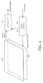
- FIG. 2A is a diagram of the LCD panel.
- the LCD panel 100 is generally divided into two regions—a display region 112 and a non-display region 114 .
- the display region 112 comprises a thin film transistor (TFT) array
- the non-display region 114 comprises a gate driver 120 and a source driver 125 for controlling transistors in the TFT array.
- the panel control signal outputted from the display controller 130 controls the gate driver 120 to generate a gate driving signal and the source driver 125 to generate a source driving signal.
- the panel control signal further comprises a common voltage signal Vcom for controlling the inversion of liquid crystal in the LCD panel 100 .
- the gate driving signal controls the TFT array to turn on or off, and the source driving signal provides brightness data for pixels.
- the display controller 130 can be integrated with a timing controller (TCON), the gate driver 120 and the source driver 125 .
- TCON timing controller
- the video signal comprises a vertical synchronization signal Vsync, a horizontal synchronization signal Hsync, a red signal, a green signal and a blue signal.
- the time to display a scan line on the LCD panel 100 is a period associated with the horizontal synchronization signal Hsync, while the time to display a frame on the LCD panel 100 is a period associated with the vertical synchronization signal Vsync. That is, if the LCD panel 100 has M scan lines, the gate driver 120 can generate M gate driving signals. According to the horizontal synchronization signal Hsync, M gate driving signals can be asserted sequentially.
- FIG. 2B is a diagram of the vertical synchronization signal Vsync, the horizontal synchronization signal Hsync, the common voltage signal Vcom and the gate driving signal.
- the period of the vertical synchronization signal Vsync begins from the start of the low level, and one period of the vertical synchronization signal Vsync comprises a plurality of periods of the horizontal synchronization signal Hsync.
- a plurality of gate driving signals are asserted sequentially, and a frequency of the common voltage signal Vcom is a half of a frequency of the horizontal synchronization signal Hsync.
- the display controller 130 can be integrated with the timing controller, the gate driver 120 and the source driver 125 , with the Vcom signal residing in the integrated display controller 130 .
- the low level interval of the vertical synchronization signal Vsync is known as a vertical blanking interval (VBI).
- VBI vertical blanking interval
- the common voltage signal Vcom also remains at the low level.
- FIG. 3 shows a conventional capacitive touch panel.
- the capacitive touch panel comprises a first sensing layer 151 , a second sensing layer 152 and a shielding layer 153 .
- the first sensing layer 151 and the second sensing layer 152 respectively comprise a plurality of capacitive sensing components. When one touches the capacitive touch panel, equivalent capacitance of the touch point is changed.
- the shielding layer 153 isolates the panel control signal from the sensing signal so that the sensing signal is not affected by noise from the panel control signal. Accordingly, the display controller 130 and the sensing circuit 155 in the conventional capacitive touch screen operate separately without communication.
- the conventional three-layered capacitive touch panel is much more costly than a resistive touch panel.
- the present invention provides a touch sensing method and associated apparatus applied to a capacitive touch screen, so that the capacitive touch panel in the capacitive touch screen requires no shielding layer to generate a position signal correctly.
- the present invention provides a touch screen comprising an LCD panel; a display controller, for processing a video signal to generate a panel control signal and a sensing control signal, with the panel control signal controlling the LCD panel so that the LCD panel displays an image according to the panel control signal; a touch panel, for generating a sensing signal in response to a touch; and a sensing circuit, coupled to the touch panel and the display controller, for receiving the sensing signal and the sensing control signal to generate a position signal with reference to the sensing control signal.
- the present invention provides a touch sensing method for sensing a touch point on the touch panel to output the position signal.
- the touch sensing method comprises generating a sensing control signal to a sensing circuit so that the sensing circuit accordingly determines a plurality of sensing periods; and within the sensing periods, detecting a sensing signal by the sensing circuit to output the position signal.
- FIG. 1 is a conventional touch screen.
- FIG. 2A is a diagram of an LCD panel according to the prior art.
- FIG. 2B is a diagram of a vertical synchronization signal Vsync, a horizontal synchronization signal Hsync, a common voltage Vcom and a gate driving signal according to the prior art.
- FIG. 3 is a diagram of a conventional capacitive touch panel
- FIG. 4 is a touch screen according to one embodiment of the present invention.
- FIG. 5 is a sensing period according to a first embodiment of the present invention.
- FIG. 6 is a sensing period according to a second embodiment of the present invention.
- FIG. 7 is a flowchart of a touch sensing method according to an embodiment of the present invention.
- a display controller and a sensing circuit operate separately, and signals between them are isolated by a shielding layer.
- a panel control signal becomes very noisy to a sensing signal, such that the sensing circuit fails to generate a correct position signal.
- a main reason for incurring excessive noise in the sensing signal is a common voltage signal Vcom. Since the amplitude of the common voltage signal Vcom is between 3V and 5V, transitions between high and low levels of the common voltage signal Vcom causes noise that is then coupled to the sensing signal.
- FIG. 4 is a touch screen according to one embodiment of the present invention.
- the touch screen comprises a liquid crystal display (LCD) panel 200 , a display controller 230 , a touch panel 250 and a sensing circuit 255 .
- the display controller 230 receives a video signal, outputs a panel control signal to the panel 200 and further outputs a sensing control (SC) signal to the sensing circuit 255 .
- the sensing circuit 255 determines a sensing period according to the SC signal.
- the sensing circuit 255 detects the sensing signal to generate the position signal within a sensing period.
- the touch panel 250 is a capacitive touch panel and no shielding layer is required.
- the sensing control SC signal and the common voltage signal Vcom are in-phase. For example, when the common voltage signal Vcom is at a high level, the sensing control signal SC is also at a high level, and when the common voltage signal Vcom is at a low level, the sensing control signal SC is also at a low level.
- the display controller 230 can be integrated with a timing controller, a gate driver and a source driver. The display controller 230 outputs the sensing control signal SC to the sensing circuit 255 so that the sensing circuit 255 determines a sensing period to detect the sensing signal and output a position signal as a result. Thus, the sensing circuit 255 can remove the noise in the sensing signal and output the correct position signal.
- FIG. 5 is a sensing period according to one embodiment of the present invention.
- the sensing circuit 255 is notified of the start time of each frame by the SC signal and determines the sensing period from the frame starting time.
- a first pulse of the SC signal is selected as the frame starting time, and the sensing control signal SC comprises four zones, i.e., A, B, C and D.
- the variation in the Vcom signal in the three zones A, B and C is the same. Hence, the three zones A, B and C can be selected as the sensing period.
- the sensing circuit 255 can remove the noise of the sensing signal and output the correct position signal. Since the zone D encompasses the VBI, its variation in the common voltage signal Vcom is different from those of the three zones A, B and C. Thus, the zone D is discarded.
- FIG. 6 is a sensing period according to another embodiment of the present invention.
- the sensing control signal SC and the common voltage signal Vcom are in-phase.
- the frame rate is 60 frame/sec
- the period for displaying one frame is around 16.6 ms
- the pulse width of the SC signal is about 30 to 40 ⁇ s.
- each sensing period of the capacitive touch panel requires 5 ⁇ s.
- the sensing circuit 255 is embedded with a delta-sigma analog to digital converter (ADC) for an in-situ detection, the sensing circuit 255 is notified of the start time of each frame by the sensing control SC, and the high levels of the sensing control SC (a to m) are determined as proper sensing periods.
- ADC analog to digital converter
- each sensing period has a guarding period to avoid an unstable zone of the signal transition period.
- each signal transition is designated with a protection zone having a predetermined time length to avoid the guarding period before the actual detection begins.
- the first pulse of the sensing control signal SC can be viewed as the start time of the frame, and the high level of the sensing control signal SC serves as the sensing period. Therefore, within the sensing periods (a to m), the common voltage signal Vcom remains at the high level, and the sensing circuit 255 removes the noise of the sensing signal with reference to the sensing control signal SC to output the correct position signal.
- the sensing circuit 255 can also use the low level of the sensing control signal SC as the sensing period. That is, the sensing control signal SC in the first and second embodiment is associated with the common voltage signal Vcom. According to the above embodiment, those skilled in the art can use the vertical synchronization signal Vsync, the horizontal synchronization signal Hsync, the red signal, the green signal or the blue signal in the display controller 230 to generate the sensing control signal SC indicating the start time of the frame to the sensing circuit 255 , which then determines the sensing period with reference to the sensing control signal SC. Alternatively, the display controller 230 generates the sensing control signal SC capable of indicating the start time of the frame to the sensing circuit 255 for determining the sensing period.
- FIG. 7 is a flowchart of a touch sensing method for sensing the touch point to output a position signal according to one embodiment of the present invention.
- the touch panel comprises a first sensing layer and a second sensing layer without a shielding layer.
- a sensing control signal is generated to the sensing circuit, which then accordingly determines a plurality of sensing periods.
- each sensing period has one guarding period.
- the sensing period resides in a non-VBI area.
- the sensing signal is detected within the sensing periods to output the position signal.
- the sensing control signal SC is capable of indicating a start time of a frame according to, for example, a vertical synchronization signal Vsync, a horizontal synchronization signal Hsync, a red signal, a green signal or a blue signal.
- the present invention provides a touch screen comprising an LCD panel; a display controller, for processing a video signal to generate a panel control signal and a sensing control signal, with the panel control signal controlling the LCD panel so that the LCD panel displays images according to the panel control signal; a touch panel, for generating a sensing signal in response to a touch; and a sensing circuit, coupled to the touch panel and the display controller, for receiving the sensing signal and the sensing control signal to generate a position signal with reference to the sensing control signal.
- the present invention also provides a touch sensing method for sensing a touch point on a touch panel to output a position signal.
- the touch sensing method comprises generating a sensing control signal to a sensing circuit that then accordingly determines a plurality of sensing periods; and within the sensing periods, detecting a sensing signal by the sensing circuit to output the position signal.
- the present invention provides a touch sensing method and associated apparatus applied to the capacitive touch screen to offer an advantage that the capacitive sensing panel in the capacitive touch screen need not be provided with the shielding layer and the sensing signal is detected within the sensing periods to determine the correct position signal.
Abstract
Description
Claims (19)
Applications Claiming Priority (3)
| Application Number | Priority Date | Filing Date | Title |
|---|---|---|---|
| TW98124451A | 2009-07-20 | ||
| TW098124451 | 2009-07-20 | ||
| TW098124451A TWI395126B (en) | 2009-07-20 | 2009-07-20 | Sensing apparatus and method applied to touch screen |
Publications (2)
| Publication Number | Publication Date |
|---|---|
| US20110012854A1 US20110012854A1 (en) | 2011-01-20 |
| US8638304B2 true US8638304B2 (en) | 2014-01-28 |
Family
ID=43464929
Family Applications (1)
| Application Number | Title | Priority Date | Filing Date |
|---|---|---|---|
| US12/838,567 Active 2031-04-11 US8638304B2 (en) | 2009-07-20 | 2010-07-19 | Touch sensing method and associated apparatus based on display panel common voltage |
Country Status (2)
| Country | Link |
|---|---|
| US (1) | US8638304B2 (en) |
| TW (1) | TWI395126B (en) |
Cited By (2)
| Publication number | Priority date | Publication date | Assignee | Title |
|---|---|---|---|---|
| US20120086656A1 (en) * | 2010-10-07 | 2012-04-12 | Mstar Semiconductor, Inc. | Touch Sensing Circuit and Associated Method |
| US9524697B2 (en) | 2014-09-02 | 2016-12-20 | Stmicroelectronics Asia Pacific Pte Ltd | Capacitive touch screen display system including circuitry to address display perturbations induced by panel sensing |
Families Citing this family (10)
| Publication number | Priority date | Publication date | Assignee | Title |
|---|---|---|---|---|
| TW201205369A (en) * | 2010-07-20 | 2012-02-01 | Novatek Microelectronics Corp | Driving method, driving device and touch sensible display device using the same |
| KR101819678B1 (en) * | 2011-04-07 | 2018-01-17 | 엘지디스플레이 주식회사 | Display having touch sensor and driving method thereof |
| TWI456467B (en) * | 2011-05-20 | 2014-10-11 | Au Optronics Corp | Operating method of capacitive touch panel and touch control barrier-type 3d display device |
| US20140062899A1 (en) * | 2012-08-31 | 2014-03-06 | Au Optronics Corporation | Dynamic stop display driving mechanism for touch sensing |
| TWI489363B (en) * | 2013-04-10 | 2015-06-21 | Orise Technology Co Ltd | Method and apparatus for reducing display interference in in-cell touch panel |
| CN105934736A (en) * | 2014-04-03 | 2016-09-07 | 积水化学工业株式会社 | Interlayer filling material for touch panel, and laminated body |
| JP6415710B2 (en) * | 2015-05-26 | 2018-10-31 | シャープ株式会社 | Display device with sensor, control device, and control method |
| JP7086553B2 (en) | 2017-09-22 | 2022-06-20 | シナプティクス・ジャパン合同会社 | How to drive the display driver, display device and display panel |
| US11320919B2 (en) * | 2017-12-14 | 2022-05-03 | Sitronix Technology Corporation | Touch and display driver integration circuit |
| JP7041036B2 (en) * | 2018-09-27 | 2022-03-23 | シャープ株式会社 | Touch panel display and touch panel display control method |
Citations (20)
| Publication number | Priority date | Publication date | Assignee | Title |
|---|---|---|---|---|
| US5410329A (en) * | 1992-05-22 | 1995-04-25 | Sharp Kabushiki Kaisha | Display-integrated type tablet device |
| US5448024A (en) * | 1993-04-30 | 1995-09-05 | Sharp Kabushiki Kaisha | Display-integrated type tablet device with high coordinate detection accuracy and method for driving the same |
| US20040217945A1 (en) * | 2001-08-22 | 2004-11-04 | Saburo Miyamoto | Touch sensor, display with touch sensor, and method for generating position data |
| US20040227743A1 (en) * | 2003-02-28 | 2004-11-18 | Brown Christopher James | Display and sensor apparatus |
| US20060132463A1 (en) * | 2004-12-03 | 2006-06-22 | Lee Joo-Hyung | Touch sensible display device |
| US20060201931A1 (en) * | 2005-03-13 | 2006-09-14 | Samsung Electronics Co., Ltd. | Touch sensible display device, and driving apparatus and method thereof |
| US20070034423A1 (en) * | 2005-08-12 | 2007-02-15 | Rebeschi Thomas J | Touch screen having reduced susceptibility to radio frequency interference |
| US20070091078A1 (en) * | 2005-10-26 | 2007-04-26 | Jong-Woung Park | Touch sensitive display device and method thereof |
| US20070262966A1 (en) * | 2004-10-22 | 2007-11-15 | Tomohiko Nishimura | Display Device with Touch Sensor, and Drive Method for the Device |
| US20080198140A1 (en) * | 2007-02-20 | 2008-08-21 | Hitachi Displays, Ltd. | Image display apparatus with image entry function |
| US20090073138A1 (en) * | 2007-09-13 | 2009-03-19 | Samsung Electronics Co., Ltd. | Display panel and display apparatus having the same |
| US20090115737A1 (en) * | 2007-11-05 | 2009-05-07 | Epson Imaging Devices Corporation | Display device and electronic apparatus |
| US20100110029A1 (en) * | 2008-10-31 | 2010-05-06 | Wacom Co., Ltd. | Position detecting device |
| US20100214259A1 (en) * | 2007-07-31 | 2010-08-26 | Harald Philipp | Sensor and method of sensing |
| US20100289765A1 (en) * | 2009-05-18 | 2010-11-18 | Sony Corporation | Display device and electronic unit |
| US20100295824A1 (en) * | 2009-05-21 | 2010-11-25 | Sony Corporation | Display device and electronic unit |
| US20100328259A1 (en) * | 2009-06-30 | 2010-12-30 | Sony Corporation | Touch sensor and display device |
| US20100328256A1 (en) * | 2009-06-29 | 2010-12-30 | Sony Corporation | Touch sensor, display and electronic unit |
| US20110050605A1 (en) * | 2009-09-02 | 2011-03-03 | Mstar Semiconductor, Inc. | Touch Sensing Module, Display Apparatus and Manufacturing Method Thereof |
| US20110267296A1 (en) * | 2010-04-30 | 2011-11-03 | Sony Corporation | Touch detection device, display device having touch detection function, electronic unit, and touch detection circuit |
Family Cites Families (2)
| Publication number | Priority date | Publication date | Assignee | Title |
|---|---|---|---|---|
| CN101470560B (en) * | 2007-12-27 | 2012-01-25 | 清华大学 | Touch screen and display equipment |
| JP5014971B2 (en) * | 2007-12-19 | 2012-08-29 | ソニーモバイルディスプレイ株式会社 | Display device |
-
2009
- 2009-07-20 TW TW098124451A patent/TWI395126B/en active
-
2010
- 2010-07-19 US US12/838,567 patent/US8638304B2/en active Active
Patent Citations (20)
| Publication number | Priority date | Publication date | Assignee | Title |
|---|---|---|---|---|
| US5410329A (en) * | 1992-05-22 | 1995-04-25 | Sharp Kabushiki Kaisha | Display-integrated type tablet device |
| US5448024A (en) * | 1993-04-30 | 1995-09-05 | Sharp Kabushiki Kaisha | Display-integrated type tablet device with high coordinate detection accuracy and method for driving the same |
| US20040217945A1 (en) * | 2001-08-22 | 2004-11-04 | Saburo Miyamoto | Touch sensor, display with touch sensor, and method for generating position data |
| US20040227743A1 (en) * | 2003-02-28 | 2004-11-18 | Brown Christopher James | Display and sensor apparatus |
| US20070262966A1 (en) * | 2004-10-22 | 2007-11-15 | Tomohiko Nishimura | Display Device with Touch Sensor, and Drive Method for the Device |
| US20060132463A1 (en) * | 2004-12-03 | 2006-06-22 | Lee Joo-Hyung | Touch sensible display device |
| US20060201931A1 (en) * | 2005-03-13 | 2006-09-14 | Samsung Electronics Co., Ltd. | Touch sensible display device, and driving apparatus and method thereof |
| US20070034423A1 (en) * | 2005-08-12 | 2007-02-15 | Rebeschi Thomas J | Touch screen having reduced susceptibility to radio frequency interference |
| US20070091078A1 (en) * | 2005-10-26 | 2007-04-26 | Jong-Woung Park | Touch sensitive display device and method thereof |
| US20080198140A1 (en) * | 2007-02-20 | 2008-08-21 | Hitachi Displays, Ltd. | Image display apparatus with image entry function |
| US20100214259A1 (en) * | 2007-07-31 | 2010-08-26 | Harald Philipp | Sensor and method of sensing |
| US20090073138A1 (en) * | 2007-09-13 | 2009-03-19 | Samsung Electronics Co., Ltd. | Display panel and display apparatus having the same |
| US20090115737A1 (en) * | 2007-11-05 | 2009-05-07 | Epson Imaging Devices Corporation | Display device and electronic apparatus |
| US20100110029A1 (en) * | 2008-10-31 | 2010-05-06 | Wacom Co., Ltd. | Position detecting device |
| US20100289765A1 (en) * | 2009-05-18 | 2010-11-18 | Sony Corporation | Display device and electronic unit |
| US20100295824A1 (en) * | 2009-05-21 | 2010-11-25 | Sony Corporation | Display device and electronic unit |
| US20100328256A1 (en) * | 2009-06-29 | 2010-12-30 | Sony Corporation | Touch sensor, display and electronic unit |
| US20100328259A1 (en) * | 2009-06-30 | 2010-12-30 | Sony Corporation | Touch sensor and display device |
| US20110050605A1 (en) * | 2009-09-02 | 2011-03-03 | Mstar Semiconductor, Inc. | Touch Sensing Module, Display Apparatus and Manufacturing Method Thereof |
| US20110267296A1 (en) * | 2010-04-30 | 2011-11-03 | Sony Corporation | Touch detection device, display device having touch detection function, electronic unit, and touch detection circuit |
Cited By (3)
| Publication number | Priority date | Publication date | Assignee | Title |
|---|---|---|---|---|
| US20120086656A1 (en) * | 2010-10-07 | 2012-04-12 | Mstar Semiconductor, Inc. | Touch Sensing Circuit and Associated Method |
| US9383856B2 (en) * | 2010-10-07 | 2016-07-05 | Mstar Semiconductor, Inc. | Touch sensing circuit and associated method |
| US9524697B2 (en) | 2014-09-02 | 2016-12-20 | Stmicroelectronics Asia Pacific Pte Ltd | Capacitive touch screen display system including circuitry to address display perturbations induced by panel sensing |
Also Published As
| Publication number | Publication date |
|---|---|
| US20110012854A1 (en) | 2011-01-20 |
| TWI395126B (en) | 2013-05-01 |
| TW201104539A (en) | 2011-02-01 |
Similar Documents
| Publication | Publication Date | Title |
|---|---|---|
| US8638304B2 (en) | Touch sensing method and associated apparatus based on display panel common voltage | |
| TWI530854B (en) | Touch sensing device and display device using the same | |
| US7893912B2 (en) | Timing controller for liquid crystal display | |
| US9019196B2 (en) | Liquid crystal display device | |
| JP5403879B2 (en) | Liquid crystal display device and driving method thereof | |
| US20070126686A1 (en) | Liquid crystal display device and method of driving the same | |
| US20100302220A1 (en) | Liquid crystal display and driving method thereof | |
| TWI590122B (en) | Driver integrated circuit and display apparatus including the same | |
| US10048797B2 (en) | Display device with data line precharging at boundary between touch driving period and display driving period | |
| CN101968581B (en) | Touch sensing method and device thereof | |
| US20080165099A1 (en) | Lcds and methods for driving same | |
| JP2010197570A (en) | Liquid crystal display device | |
| KR20140076054A (en) | Display device having touch sensors and control method of gate driving circuit thereof | |
| JP2009109955A (en) | Timing controller for matrix display device, and liquid crystal display device adopting the same | |
| WO2015196648A1 (en) | In-cell touch display screen, and drive display method and display device thereof | |
| CN110047448B (en) | Touch panel control device, touch panel control method, and input display device | |
| KR20070080170A (en) | Liquid crystal display apparatus and method of driving the same | |
| US8547310B2 (en) | Liquid crystal display device and method for selecting overdriving when the pixel data is motion image data | |
| KR102352751B1 (en) | Touch Device And Method Of Driving The Same | |
| CN106648239B (en) | Display device and display panel for compensating display interruption | |
| CN105677276B (en) | Black insertion processing method and device and display device | |
| KR102265238B1 (en) | In-cell touch type liquid crystal display device | |
| KR102474338B1 (en) | Liquid crystal display device and the method for driving the same | |
| JP7290560B2 (en) | Touch panel display and control method for touch panel display | |
| US20100177067A1 (en) | Method and circuit for controlling timings of display devices using a single data enable signal |
Legal Events
| Date | Code | Title | Description |
|---|---|---|---|
| AS | Assignment |
Owner name: MSTAR SEMICONDUCTOR, INC., TAIWAN Free format text: ASSIGNMENT OF ASSIGNORS INTEREST;ASSIGNORS:LIU, CHI KANG;LIN, CHIN-WEI;SIGNING DATES FROM 20100714 TO 20100715;REEL/FRAME:024703/0192 |
|
| STCF | Information on status: patent grant |
Free format text: PATENTED CASE |
|
| FPAY | Fee payment |
Year of fee payment: 4 |
|
| AS | Assignment |
Owner name: ILI TECHNOLOGY CORP., TAIWAN Free format text: ASSIGNMENT OF ASSIGNORS INTEREST;ASSIGNOR:MSTAR SEMICONDUCTOR, INC.;REEL/FRAME:047597/0157 Effective date: 20181127 |
|
| AS | Assignment |
Owner name: ILI TECHNOLOGY HOLDING CORPORATION, CAYMAN ISLANDS Free format text: ASSIGNMENT OF ASSIGNORS INTEREST;ASSIGNOR:ILI TECHNOLOGY CORP.;REEL/FRAME:055257/0614 Effective date: 20201210 |
|
| MAFP | Maintenance fee payment |
Free format text: PAYMENT OF MAINTENANCE FEE, 8TH YEAR, LARGE ENTITY (ORIGINAL EVENT CODE: M1552); ENTITY STATUS OF PATENT OWNER: LARGE ENTITY Year of fee payment: 8 |
|
| AS | Assignment |
Owner name: ILI TECHNOLOGY CORP., TAIWAN Free format text: ASSIGNMENT OF ASSIGNORS INTEREST;ASSIGNOR:ILI TECHNOLOGY HOLDING CORPORATION;REEL/FRAME:060262/0911 Effective date: 20220322 |