US8625656B2 - Channel estimation for wireless communication - Google Patents

Channel estimation for wireless communication Download PDF

Info

Publication number
US8625656B2
US8625656B2 US12/717,598 US71759810A US8625656B2 US 8625656 B2 US8625656 B2 US 8625656B2 US 71759810 A US71759810 A US 71759810A US 8625656 B2 US8625656 B2 US 8625656B2
Authority
US
United States
Prior art keywords
filter
signal
channel
channel estimate
channel estimation
Prior art date
Legal status (The legal status is an assumption and is not a legal conclusion. Google has not performed a legal analysis and makes no representation as to the accuracy of the status listed.)
Active, expires
Application number
US12/717,598
Other versions
US20100158176A1 (en
Inventor
Tao Luo
Aleksandar Damnjanovic
Durga Prasad Malladi
Current Assignee (The listed assignees may be inaccurate. Google has not performed a legal analysis and makes no representation or warranty as to the accuracy of the list.)
Qualcomm Inc
Original Assignee
Qualcomm Inc
Priority date (The priority date is an assumption and is not a legal conclusion. Google has not performed a legal analysis and makes no representation as to the accuracy of the date listed.)
Filing date
Publication date
Application filed by Qualcomm Inc filed Critical Qualcomm Inc
Priority to US12/717,598 priority Critical patent/US8625656B2/en
Assigned to QUALCOMM INCORPORATED reassignment QUALCOMM INCORPORATED ASSIGNMENT OF ASSIGNORS INTEREST (SEE DOCUMENT FOR DETAILS). Assignors: DAMNJANOVIC, ALEKSANDAR, LUO, TAO, MALLADI, DURGA PRASAD
Publication of US20100158176A1 publication Critical patent/US20100158176A1/en
Application granted granted Critical
Publication of US8625656B2 publication Critical patent/US8625656B2/en
Active legal-status Critical Current
Adjusted expiration legal-status Critical

Links

Images

Classifications

    • HELECTRICITY
    • H04ELECTRIC COMMUNICATION TECHNIQUE
    • H04LTRANSMISSION OF DIGITAL INFORMATION, e.g. TELEGRAPHIC COMMUNICATION
    • H04L25/00Baseband systems
    • H04L25/02Details ; arrangements for supplying electrical power along data transmission lines
    • H04L25/0202Channel estimation
    • HELECTRICITY
    • H04ELECTRIC COMMUNICATION TECHNIQUE
    • H04BTRANSMISSION
    • H04B1/00Details of transmission systems, not covered by a single one of groups H04B3/00 - H04B13/00; Details of transmission systems not characterised by the medium used for transmission
    • H04B1/69Spread spectrum techniques
    • H04B1/707Spread spectrum techniques using direct sequence modulation
    • H04B1/7097Interference-related aspects
    • H04B1/7103Interference-related aspects the interference being multiple access interference
    • H04B1/7107Subtractive interference cancellation
    • H04B1/71072Successive interference cancellation
    • HELECTRICITY
    • H04ELECTRIC COMMUNICATION TECHNIQUE
    • H04BTRANSMISSION
    • H04B7/00Radio transmission systems, i.e. using radiation field
    • H04B7/02Diversity systems; Multi-antenna system, i.e. transmission or reception using multiple antennas
    • H04B7/04Diversity systems; Multi-antenna system, i.e. transmission or reception using multiple antennas using two or more spaced independent antennas
    • H04B7/0413MIMO systems
    • HELECTRICITY
    • H04ELECTRIC COMMUNICATION TECHNIQUE
    • H04LTRANSMISSION OF DIGITAL INFORMATION, e.g. TELEGRAPHIC COMMUNICATION
    • H04L25/00Baseband systems
    • H04L25/02Details ; arrangements for supplying electrical power along data transmission lines
    • H04L25/0202Channel estimation
    • H04L25/0224Channel estimation using sounding signals
    • H04L25/0226Channel estimation using sounding signals sounding signals per se
    • HELECTRICITY
    • H04ELECTRIC COMMUNICATION TECHNIQUE
    • H04LTRANSMISSION OF DIGITAL INFORMATION, e.g. TELEGRAPHIC COMMUNICATION
    • H04L25/00Baseband systems
    • H04L25/02Details ; arrangements for supplying electrical power along data transmission lines
    • H04L25/0202Channel estimation
    • H04L25/0238Channel estimation using blind estimation

Definitions

  • the present disclosure relates generally to communication, and more specifically to techniques for performing channel estimation.
  • a transmitter In a wireless communication system, a transmitter typically processes (e.g., encodes and modulates) traffic data to generate data symbols. In a coherent system, the transmitter multiplexes pilot symbols with the data symbols, processes the multiplexed data and pilot symbols to generate a modulated signal, and transmits the modulated signal via a wireless channel. The wireless channel distorts the transmitted signal with a channel response and further degrades the signal with noise and interference.
  • a receiver receives the transmitted signal and processes the received signal to obtain input samples. For coherent data detection, the receiver estimates the response of the wireless channel based on received pilot symbols and derives a channel estimate. The receiver then performs data detection on the input samples with the channel estimate to obtain detected symbols, which are estimates of the data symbols sent by the transmitter. The receiver then processes (e.g., demodulates and decodes) the detected symbols to obtain decoded data.
  • the quality of the channel estimate may have a large impact on data detection performance and may affect the quality of the detected symbols as well as the reliability of the decoded data. There is therefore a need in the art for techniques to derive a high quality channel estimate for wireless communication.
  • an apparatus which includes at least one processor and a memory.
  • the processor(s) determine a filter selection metric for a signal to be recovered, select a channel estimation filter based on the filter selection metric, and derive a channel estimate with the selected channel estimation filter.
  • an apparatus which includes at least one processor and a memory.
  • the processor(s) derive a first channel estimate based on pilot symbols and with a first channel estimation filter.
  • the processor(s) recover a first packet with the first channel estimate and regenerate data symbols for the first packet.
  • the processor(s) derive a second channel estimate based on the data symbols and with a second channel estimation filter, and obtains a third channel estimate based on the first and second channel estimates.
  • an apparatus which includes at least one processor and a memory.
  • the processor(s) derive a first channel estimate with a first channel estimation filter having a first filter response, recover a first signal with the first channel estimate, and estimate and remove interference due to the first signal.
  • the processor(s) derive a second channel estimate with a second channel estimation filter having a second filter response that is different from the first filter response.
  • FIG. 1 shows a wireless communication system
  • FIG. 2 shows a frame format and a slot format in W-CDMA.
  • FIG. 3 shows a block diagram of a base station and a terminal
  • FIG. 4 shows a block diagram of a CDMA modulator at the terminal.
  • FIG. 5 shows a block diagram of a receive (RX) processor at the base station.
  • FIG. 6 shows a block diagram of an RX processor with different channel estimation filters for pilot and data symbols.
  • FIG. 7 shows a block diagram of an RX processor with interference cancellation.
  • FIG. 8 shows a block diagram of a transmitter and a receiver for a MIMO transmission.
  • FIG. 9 shows a block diagram of an RX processor with interference cancellation.
  • FIG. 10 shows a process for recovering a signal.
  • FIG. 11 shows a process for recovering a signal with different channel estimates.
  • FIG. 12 shows a process for recovering multiple signals.
  • exemplary is used herein to mean “serving as an example, instance, or illustration.” Any exemplary embodiment described herein as “exemplary” is not necessarily to be construed as preferred or advantageous over other exemplary embodiments.
  • FIG. 1 shows a wireless communication system 100 .
  • FIG. 1 shows only one base station 110 and three terminals 120 .
  • a base station is generally a fixed station that communicates with the terminals and may also be called a Node B, an access point, a base transceiver station (BTS), or some other terminology.
  • a base station may communicate with one or more terminals on the downlink and uplink.
  • the downlink (or forward link) refers to the communication link from the base station to the terminals
  • the uplink (or reverse link) refers to the communication link from the terminals to the base station.
  • a terminal may be stationary or mobile and may also be called a user equipment (UE), a mobile station, a user terminal, a subscriber unit, or some other terminology.
  • a terminal may be a cellular phone, a personal digital assistant (PDA), a wireless device, a wireless modem card, a handheld device, or some other device or apparatus.
  • PDA personal digital assistant
  • the terms “terminal” and “user” are used interchangeably.
  • base station 110 may transmit one or more downlink signals to terminals 120 .
  • Each downlink signal may reach each terminal 120 via one or more signal paths, which may include a direct path and/or reflected paths. The reflected paths are created by reflections of radio waves due to obstructions (e.g., buildings, trees, vehicles, and other structures) in the wireless environment.
  • Each terminal 120 may receive multiple instances or copies of each downlink signal. Each received signal instance is obtained via a different signal path and has a particular complex gain and a particular time delay determined by that signal path. The received signal at each terminal 120 is a superposition of all received signal instances for base station 110 .
  • each terminal 120 may transmit one or more uplink signals to base station 110 .
  • Each uplink signal may reach base station 110 via one or more signal paths.
  • the received signal at base station 110 is a superposition of all received signal instances for all terminals transmitting on the uplink.
  • CDMA Code Division Multiple Access
  • TDMA Time Division Multiple Access
  • FDMA Frequency Division Multiple Access
  • OFDMA Orthogonal FDMA
  • SC-FDMA Single-Carrier FDMA
  • a CDMA system may implement a radio technology such as cdma2000, Universal Terrestrial Radio Access (UTRA) Frequency Division Duplexing (FDD), or UTRA Time Division Duplexing (TDD).
  • cdma2000 covers IS-2000, IS-95 and IS-856 standards.
  • UTRA FDD is also referred to as Wideband-CDMA (W-CDMA).
  • a TDMA system may implement a radio technology such as Global System for Mobile Communications (GSM).
  • GSM Global System for Mobile Communications
  • UTRA FDD, UTRA TDD, and GSM are described in documents from an organization named “3rd Generation Partnership Project” (3GPP).
  • cdma2000 is described in documents from an organization named “3rd Generation Partnership Project 2” (3GPP2).
  • 3GPP and 3GPP2 documents are publicly available.
  • the channel estimation techniques may be used for downlink and uplink transmissions and may be implemented at a base station as well as a terminal. For clarity, the techniques are described below for uplink transmission in W-CDMA.
  • FIG. 2 shows a frame format in W-CDMA.
  • the timeline for transmission is divided into radio frames.
  • Each radio frame has a duration of 10 milliseconds (ms) and is identified by a 12-bit system frame number (SFN).
  • SFN system frame number
  • Each radio frame is further partitioned into 15 slots, which are labeled as slot 0 through slot 14.
  • Each slot has a duration of 0.667 ms and includes 2560 chips at 3.84 Mcps.
  • Each ratio frame is also partitioned into five subframes.
  • Each subframe has a duration of 2 ms and includes 3 slots.
  • FIG. 2 also shows a slot format for an uplink dedicated physical channel (DPCH) used by a terminal to send traffic and other data on the uplink.
  • the uplink DPCH includes a dedicated physical data channel (DPDCH) that carries traffic data and a dedicated physical control channel (DPCCH) that carries pilot and control data.
  • DPDCH dedicated physical data channel
  • DPCCH dedicated physical control channel
  • a radio link for a terminal may include zero, one, or multiple DPDCHs and only one DPCCH.
  • Each slot of the DPCCH includes a pilot field, a transport format combination indicator (TFCI) field, a feedback information (FBI) field, and a transmit power control (TPC) field.
  • the pilot field carries pilot symbols.
  • the TFCI field carries format information used to recover the traffic data.
  • the FBI field carries feedback from a terminal to a base station, e.g., for transmit diversity.
  • the TPC field carries power control information to direct the base station to adjusts its transmit power for downlink transmission to the terminal.
  • the number of bits in each field is zero or greater and is determined by a slot format selected for use.
  • FIG. 2 also shows a slot format for an E-DCH DPDCH (E-DPDCH) that carries traffic data and an E-DCH DPCCH (E-DPCCH) that carries control data.
  • E-DPDCH E-DCH DPDCH
  • E-DPCCH E-DCH DPCCH
  • a radio link for a terminal may include zero, one, or multiple E-DPDCHs and at most one E-DPCCH.
  • FIG. 3 shows a block diagram of base station 110 and terminal 120 , which is one of the terminals in FIG. 1 .
  • a transmit (TX) data processor 310 receives data packets, processes (e.g., encodes, interleaves, and symbol maps) each packet, and generates data symbols.
  • a packet may also be referred to as a transport block, a frame, and so on.
  • a data symbol is a symbol for data
  • a pilot symbol is a symbol for pilot
  • pilot is data that is known a priori by both the terminal and base station.
  • the data and pilot symbols may be modulation symbols from a signal constellation for PSK, QAM, or some other modulation scheme.
  • TX data processor 310 also appends a cyclic redundancy check (CRC) value to each packet, which is used to determine whether the packet is decoded correctly or in error.
  • CRC cyclic redundancy check
  • a CDMA modulator 320 processes the data symbols and pilot symbols and provides output chips to a transmitter (TMTR) 330 .
  • Transmitter 330 processes (e.g., converts to analog, amplifies, filters, and frequency upconverts) the output chips and generates an uplink signal, which is transmitted from an antenna 332 .
  • an antenna 352 receives the uplink signals from terminal 120 as well as other terminals via direct and/or reflected paths.
  • Antenna 352 provides a received signal to a receiver (RCVR) 354 .
  • Receiver 354 processes (e.g., filters, amplifies, frequency downconverts, and digitizes) the received signal and provides input samples to an RX processor 360 .
  • RX processor 360 processes (e.g., filters, amplifies, frequency downconverts, and digitizes) the received signal and provides input samples to an RX processor 360 .
  • a CDMA demodulator (Demod) 362 processes the input samples and provides detected symbols, which are estimates of the data symbols sent by terminal 120 .
  • CDMA demodulator 362 may implement a rake receiver and/or an equalizer, each of which can combine energy from multiple signal paths.
  • An RX data processor 364 processes (e.g., symbol demaps, deinterleaves, and decodes) the detected symbols and provides decoded data.
  • CDMA demodulator 362 and RX data processor 364 is complementary to the processing by CDMA modulator 320 and TX data processor 310 , respectively, at terminal 120 .
  • Controllers/processors 340 and 370 direct operation of various processing units at terminal 120 and base station 110 , respectively.
  • Memories 342 and 372 store data and program codes for terminal 120 and base station 110 , respectively.
  • FIG. 4 shows a block diagram of CDMA modulator 320 at terminal 120 .
  • a spreader 412 spreads data symbols for the DPDCH with a channelization code C d and provides data chips.
  • Spreader 412 repeats each data symbol to generate N replicated symbols, where N is the length of code C d .
  • Spreader 412 then multiplies the N replicated symbols with the N chips of code C d to generate N data chips for the data symbol.
  • a multiplier 414 multiplies the output of spreader 412 with a gain factor ⁇ d for the DPDCH.
  • a multiplier 416 multiplies the output of multiplier 414 with iq d , which may be +1 or j, and provides chips for the DPDCH.
  • a spreader 422 spreads pilot and control symbols for the DPCCH with a channelization code C c .
  • a multiplier 424 multiplies the output of spreader 422 with a gain factor ⁇ c for the DPCCH.
  • a spreader 432 spreads data symbols for the E-DPDCH with a channelization code C ed .
  • a multiplier 434 multiplies the output of spreader 432 with a gain factor ⁇ ed for the E-DPDCH.
  • a spreader 442 spreads control symbols for the E-DPCCH with a channelization code C ec .
  • a multiplier 444 multiplies the output of spreader 442 with a gain factor ⁇ ec for the E-DPCCH.
  • a summer 448 sums the chips from multipliers 416 , 426 , 436 and 446 and provides complex-valued chips.
  • a scrambler 450 multiplies the output of summer 448 with a scrambling code S dpch,n for terminal 120 and provides output chips.
  • zero, one or more DPDCHs and zero, one or more E-DPDCHs may be sent on each of the inphase (I) and quadrature (Q) paths.
  • Each DPDCH is spread with a different channelization code C d having a length of 4 to 256 chips, which correspond to 960 to 15 kbps, respectively.
  • Each E-DPDCH is spread with a different channelization code C ed having a length of 2 or 4 chips, which correspond to 1920 or 960 kbps, respectively.
  • the DPCCH is sent on the Q path and is spread with a 256-chip channelization code C c .
  • the DPCCH carries 10 symbols in each slot, and the pilot field may carry 3 to 8 pilot symbols.
  • the E-DPCCH is sent on the I path and is spread with a 256-chip channelization code C ec .
  • the gain factors ⁇ d and ⁇ ed determine the amount of transmit power to use for traffic data.
  • the gain factors ⁇ c and ⁇ ec determine the amount of transmit power to use for pilot and control data.
  • the traffic-to-pilot ratio is typically selected to achieve good channel estimation performance and may range, e.g., from 0 to 20 dB.
  • Base station 110 may estimate the response of the uplink channel for terminal 120 based on pilot symbols and/or data symbols sent by the terminal. Base station 110 may derive a pilot-based channel estimate with the pilot symbols, which may be sent using code division multiplexing as shown in FIG. 4 . Base station 110 may derive a data-based channel estimate with the data symbols, e.g., after a packet has been successfully decoded.
  • channel estimation performance is affected by two competing factors—noise suppression and channel tracking.
  • noise suppression and channel tracking For a slowly varying channel, it is desirable to derive a channel estimate with as many symbols as possible since the channel gains change slowly and the quality of the channel estimate typically improves by using more symbols.
  • For a fast fading channel it is desirable to derive a channel estimate with fewer symbols since channel variation limits the number of symbols that can be coherently combined.
  • channel estimates are derived with different channel estimation filters designed for different channel conditions.
  • the channel conditions may be quantified by SNR, mobility, fading, and/or other factors, and may be explicitly or implicitly determined as described below.
  • the channel estimation filters may be implemented with various designs.
  • the channel estimation filters are implemented with finite impulse response (FIR) filters, as follows:
  • the channel estimation filters may also be implemented with other types of filters.
  • each channel estimation filter has a specific filter length L m and a specific set of filter coefficients W m (i,k). Different coefficients may be used for different taps, so that W m (i,k) is a function of tap index k. Alternatively, the same coefficient may be used for all taps, so that W m (i) is not a function of tap index k.
  • each channel estimation filter has a different coefficient ⁇ m .
  • any number of channel estimation filters may be defined for any channel conditions.
  • two channel estimation filters are implemented with FIR filters.
  • the second filter has a length of three or four slots and different coefficients for the slots.
  • the first filter may be used for high SNR, high mobility, and/or fast fading.
  • the second filter may be used for low SNR, low mobility, and/or slow fading.
  • a suitable channel estimation filter is selected from among all available channel estimation filters based on a filter selection metric.
  • This metric may relate to SNR, mobility, fading, and/or other factors.
  • the metric indicates whether a channel estimate is derived based on pilot symbols or data symbols.
  • the metric corresponds to the traffic-to-pilot ratio.
  • a power control mechanism may adjust the transmit power such that the pilot SNR is maintained at a target SNR, which may be ⁇ 20 dB or some other value.
  • the data SNR may be determined based on the pilot SNR and the traffic-to-pilot ratio.
  • the metric corresponds to a packet format selected for use.
  • the metric corresponds to an SNR determined based on received pilot symbols and/or received data symbols.
  • the metric relates to mobility (or Doppler spread), which may be estimated with pilot correlation or in some other manners known in the art. The metric may also be defined in other manners.
  • FIG. 5 shows a block diagram of an RX processor 360 a , which is an exemplary embodiment of RX processor 360 in FIG. 3 .
  • a pilot despreader 512 despreads the input samples (e.g., with channelization code C c for the DPCCH) and provides despread pilot symbols.
  • a unit 514 removes the modulation on the despread pilot symbols and provides channel gain estimates.
  • a channel estimation filter 516 receives the channel gain estimates and a filter selection metric. Filter 516 selects a suitable filter from among all possible filters based on the metric. Filter 516 then filters the channel gain estimates with the selected filter, e.g., as shown in equation (1) or (2), and provides a pilot-based channel estimate, CHP.
  • a data despreader 522 despreads the input samples (e.g., with channelization code C d for the DPDCH or channelization code C ed for the E-DPDCH) and provides despread data symbols.
  • a demodulator/decoder 524 performs data detection on the despread data symbols with the pilot-based channel estimate to obtain detected symbols. Unit 524 further deinterleaves and decodes the detected symbols to obtain decoded data.
  • a CRC checker 526 checks each decoded packet and determines whether the packet is decoded correctly or in error.
  • FIG. 6 shows a block diagram of an RX processor 360 b , which is another exemplary embodiment of RX processor 360 in FIG. 3 .
  • RX processor 360 b includes despreaders 512 and 522 , pilot modulation removal unit 514 , channel estimation filter 516 , demodulator/decoder 524 , and CRC checker 526 , which operate as described above for FIG. 5 .
  • an encoder/modulator 528 processes (e.g., encodes, interleaves, and modulates) the decoded packet in the same manner as terminal 120 and provides regenerated data symbols.
  • a unit 534 removes the modulation on the despread data symbols with the regenerated data symbols and provides data-based channel gain estimates ⁇ d (n,k).
  • a channel estimation filter 536 filters the channel gain estimates ⁇ d (n,k) and provides a data-based channel estimate, CHD.
  • the channel gain estimates ⁇ d (n,k) from unit 534 may be derived from many data symbols that have been correctly decoded and re-encoded and may thus be more reliable than the pilot-based channel gain estimates ⁇ p (n,k) from unit 514 .
  • filter 536 may implement a filter that can provide good performance for high SNR.
  • a combiner 538 receives the pilot-based channel estimate CHP from filter 516 and the data-based channel estimate CHD from filter 536 .
  • Combiner 538 may select one of the two channel estimates or may combine the two channel estimates.
  • Combiner 538 may provide the data-based channel estimate if certain criteria are satisfied and may provide the pilot-based channel estimate otherwise. For example, combiner 538 may provide the data-based channel estimate if it is available and not stale (e.g., obtained within a predetermined number of slots), if the traffic-to-pilot ratio is above a particular threshold, and so on.
  • Combiner 538 may also combine the pilot-based and data-based channel estimates, e.g., if the traffic-to-pilot ratio is within a particular range, and may disable combining otherwise.
  • a decision on whether to combine or not combine may be made based on the qualities of the two channel estimates, which may be inferred from the traffic-to-pilot ratio. Good performance may be achieved by combining the channel estimates if their SNRs are similar and by using the better channel estimate if their SNRs are sufficiently different.
  • Combiner 538 may weigh the pilot-based and data-based channel estimates (e.g., based on the SNRs of these channel estimates) and then combine the weighted channel estimates.
  • Combiner 538 may also perform unweighted averaging of the pilot-based and data-based channel estimates. In any case, combiner 538 provides a channel estimate for demodulator/decoder 524 .
  • Base station 110 may receive uplink transmissions from multiple terminals.
  • base station 110 processes the input samples from receiver 354 independently for each terminal, e.g., as shown in FIG. 5 or 6 , to recover the uplink transmission from that terminal.
  • the uplink transmission from each terminal acts as interference to the other terminals.
  • base station 110 recovers the uplink transmissions using interference cancellation.
  • base station 110 processes the input samples from receiver 354 to recover the uplink transmission from one terminal, estimates the interference due to this terminal, and subtracts the interference from the input samples to obtain input samples for the next terminal.
  • Base station 110 may recover the uplink transmission from each remaining terminal in the same manner. By removing the interference from terminals that are successfully decoded, higher SNRs may be achieved for terminals that are recovered later.
  • FIG. 7 shows a block diagram of an RX processor 360 c , which performs interference cancellation and is yet another exemplary embodiment of RX processor 360 in FIG. 3 .
  • RX processor 360 c includes despreaders 512 and 522 , modulation removal units 514 and 534 , channel estimation filters 516 and 536 , combiner 538 , demodulator/decoder 524 , CRC checker 526 , and encoder/modulator 528 , which operate as described above for FIG. 6 except for the following differences.
  • despreaders 512 and 522 receive input samples for terminal u. These input samples may or may not be the input samples from receiver 354 depending on whether or not terminal u is the first terminal being recovered.
  • channel estimation filter 516 (instead of combiner 538 ) provides a pilot-based channel estimate, CHPu, for terminal u to demodulator/decoder 524 .
  • channel estimation filter 536 provides a data-based channel estimate, CHDu, for terminal u.
  • encoder/modulator 528 processes the decoded packet and provides regenerated data symbols for terminal u.
  • a CDMA modulator 540 then spreads and scrambles the regenerated data symbols (and possibly pilot and control symbols) and generates output chips for terminal u.
  • a channel emulator 542 receives the output chips from CDMA modulator 540 and a channel estimate from combiner 538 , convolves the output chips with the channel estimate, and provides an interference estimate for terminal u.
  • Channel emulator 542 simulates the effects of the wireless channel for terminal u.
  • An interference subtraction unit 544 subtracts the interference estimate from the input samples for terminal u and provides input samples for the next terminal u+1.
  • the data-based channel estimate CHDu from filter 536 is used to derive an interference estimate for terminal u.
  • the data-based channel estimate may also be used for demodulation and decoding for terminal u in similar manner as shown in FIG. 6 . For example, whenever a packet is decoded correctly, the data-based channel estimate is derived from the regenerated data symbols for this packet and used for interference estimation for the present packet as well as demodulation/decoding for the next packet.
  • Combiner 538 may combine pilot-based and data-based channel estimates using any of the criteria described above for FIG. 6 and/or other criteria applicable for interference cancellation. For example, combiner 538 may provide the pilot-based channel estimate for the first stage or the first few stages. Combiner 538 may provide the data-based channel estimate or may combine the pilot-based and data-based channel estimates for the remaining stages.
  • FIG. 7 shows the processing for one terminal in one stage.
  • U terminals may be processed sequentially in U stages, one terminal in each stage.
  • the first stage processes the input samples from receiver 354 for the first terminal and provides input samples for the second stage.
  • Each subsequent stage processes the input samples from a preceding stage for one terminal and provides input samples for the next stage.
  • the terminals may also be processed with parallel interference cancellation.
  • all terminals may be processed in the first round.
  • the interference from all terminals successfully decoded in the first round may be estimated and subtracted from the input samples.
  • Terminals not successfully decoded in the first round may then be processed again using the interference-canceled input samples. The processing may continue until all terminals are successfully decoded or the interference from all successfully decoded terminals has been canceled.
  • a combination of sequential and parallel interference cancellation may also be performed.
  • the terminals may be arranged into groups, e.g., based on their SNRs. The groups may be processed sequentially, and the terminals in each group may be processed in parallel.
  • the SNR of each terminal is dependent on the stage/order in which the terminal is recovered.
  • the SNR of the first terminal may be the worst since no interference has been removed.
  • the SNR of the next terminal may be better since the interference from the first terminal has been removed.
  • the SNR of the last terminal may be the best since the interference from all prior terminals have been removed. In general, SNR progressively improves the later a terminal is recovered.
  • a large variation in SNRs may be present in the symbols used to derive channel estimates.
  • the large SNR variation may result from interference cancellation and/or from using different types of symbols, e.g., pilot symbols and data symbols, for channel estimation.
  • the channel estimation filtering may be matched to the variation in SNRs to obtain higher quality channel estimates.
  • the channel estimation filters for each terminal may be selected based on the SNR for that terminal, which may be dependent on the stage/order in which the terminal is recovered as well as where within the stage the filters are used.
  • channel estimation filter 516 may be for low SNR
  • channel estimation filter 536 may be for low or medium SNR.
  • filters 516 and 536 may be for progressively higher SNR.
  • filter 516 for successively later stages may be for progressively higher SNR.
  • Filter 536 for successively later stages may also be for progressively higher SNR.
  • filter 536 may be for higher SNR than filter 516 .
  • the particular filters to use for each stage may be appropriately selected from among all channel estimation filters available for use.
  • the channel estimation techniques described herein may also be used for data sent with hybrid automatic repeat request (H-ARQ).
  • H-ARQ a transmitter sends one or multiple transmissions for a packet until the packet is decoded correctly by a receiver or the maximum number of transmissions has been sent for the packet.
  • H-ARQ improves reliability for data transmission and supports rate adaptation for packets in the presence of changes in channel conditions.
  • demodulator/decoder 524 may store all transmissions for the packet, combine the stored transmissions with a current transmission, and demodulate and decode the combined transmission to recover the packet.
  • Different channel estimation filters may be used for different transmissions of a given packet, which may be associated with different SNRs.
  • the channel estimation techniques described herein may be used for single-input single-output (SISO), single-input multiple-output (SIMO), multiple-input single-output (MISO), and multiple-input multiple-output (MIMO) transmissions.
  • SISO single-input single-output
  • SIMO single-input multiple-output
  • MISO multiple-input single-output
  • MIMO multiple-input multiple-output
  • Single-input refers to the use of a single transmit antenna
  • multiple-input refers to the use of multiple transmit antennas for data transmission.
  • Single-output refers to the use of a single receive antenna
  • multiple-output refers to the use of multiple receive antennas for data reception.
  • FIG. 8 shows a block diagram of a transmitter 810 and a receiver 850 for MIMO transmission.
  • transmitter 810 may be part of base station 110
  • receiver 850 may be part of terminal 120 .
  • transmitter 810 may be part of terminal 120
  • receiver 850 may be part of base station 110 .
  • Transmitter 110 is equipped with multiple (T) transmit antennas.
  • Receiver 850 is equipped with multiple (R) receive antennas.
  • a TX data processor 820 processes data packets and generates S streams of data symbols, where 1 ⁇ S ⁇ min ⁇ T, R ⁇ . Each packet may be sent in one stream or across multiple streams.
  • a TX spatial processor 822 multiplexes pilot symbols with the data symbols, performs spatial mapping on the multiplexed symbols, and provides T output chip streams to T transmitters 824 a through 824 t .
  • Each transmitter 824 processes its output chip stream and generates a modulated signal. T modulated signals from transmitters 824 a through 824 t are transmitted from antennas 826 a through 826 t , respectively.
  • R antennas 852 a through 852 r receive the modulated signals from transmitter 810 , and each antenna 852 provides a received signal to a respective receiver 854 .
  • Each receiver 854 processes its received signal and provides input samples.
  • an RX spatial processor 862 performs MIMO detection on the input samples and provides detected symbols.
  • An RX data processor 864 further processes (e.g., deinterleaves and decodes) the detected symbols and provides decoded packets.
  • Controllers/processors 830 and 870 control the operation at transmitter 810 and receiver 850 , respectively.
  • Memories 832 and 872 store data and program codes for transmitter 810 and receiver 850 , respectively.
  • FIG. 9 shows a block diagram of an RX processor 860 a , which is an exemplary embodiment of RX processor 860 in FIG. 8 .
  • RX processor 860 a recovers the transmissions from transmitter 810 with successive interference cancellation (SIC).
  • SIC successive interference cancellation
  • a channel estimator 912 a derives a channel estimate CH 1 , e.g., based on pilot symbols.
  • a MIMO detectors 914 a performs MIMO detection on the R streams of input samples from receivers 854 a through 854 r and provides detected symbols D 1 for the first data stream being recovered. MIMO detectors 914 a may implement zero-forcing (ZF), minimum mean square error (MMSE), or some other MIMO detection scheme.
  • ZF zero-forcing
  • MMSE minimum mean square error
  • a demodulator/decoder 916 a demodulates, deinterleaves and decodes the detected symbols to obtain a decoded packet and further determines whether the packet is decoded correctly or in error.
  • an encoder/modulator 918 a encodes, interleaves and modulates the packet to regenerate the data symbols.
  • a channel estimator 924 a derives a data-based channel estimate CHD 1 based on the regenerated data symbols and the detected symbols D 1 .
  • a combiner 926 a selectively combines the channel estimate CH 1 from channel estimator 912 a and the data-based channel estimate CHD 1 from channel estimator 924 a and provides a channel estimate CH 2 .
  • An interference estimator 920 a estimates the interference due to the decoded packet based on the regenerated data symbols and the channel estimate CH 2 .
  • An interference subtraction unit 922 a subtracts the interference estimate from the input samples and provides input samples for the next stage.
  • Each subsequent stage may perform processing on the input samples for that stage with the channel estimate from the prior stage, in similar manner as the first stage.
  • Each stage provides input samples and channel estimate for the next stage.
  • the SNR generally improves for later stages.
  • Different channel estimation filters may be used for channel estimators 912 and/or 924 in different stages and may be selected based on the SNRs for these stages.
  • filter 924 for successively later stages may be for progressively higher SNR.
  • the particular filter to use for each stage may be appropriately selected from among all channel estimation filters available for use.
  • FIG. 10 shows an exemplary embodiment of a process 1000 for recovering a signal with a selectable channel estimation filter.
  • a filter selection metric is determined for a signal to be recovered (block 1012 ). The filter selection metric may be determined based on whether pilot symbols or data symbols are used to derive a channel estimate, a traffic-to-pilot ratio for the signal, an order in which the signal is recovered among multiple signals to be recovered, an SNR of the signal, mobility, and/or other information.
  • a channel estimation filter is selected based on the filter selection metric (block 1014 ). Multiple channel estimation filters with different lengths and/or frequency responses may be available, e.g., for different SNR ranges.
  • a suitable channel estimation filter may be selected, e.g., based on the SNR explicitly or implicitly indicated by the filter selection metric.
  • a channel estimate is derived with the selected channel estimation filter (block 1016 ).
  • the signal is then recovered with the channel estimate (block 1018 ).
  • FIG. 11 shows an exemplary embodiment of a process 1100 for recovering a signal with different channel estimates.
  • a first channel estimate is derived based on pilot symbols and with a first channel estimation filter (block 1112 ).
  • a first packet is recovered with the first channel estimate (block 1114 ).
  • Data symbols for the first packet are regenerated (block 1116 ).
  • a second channel estimate is derived based on the data symbols and with a second channel estimation filter (block 1118 ).
  • a third channel estimate is obtained based on the first and second channel estimates (block 1120 ).
  • the second channel estimate may be provided as the third channel estimate, e.g., if the quality of the second channel estimate exceeds the quality of the first channel estimate by a predetermined amount, which may be determined by a traffic-to-pilot ratio.
  • the first and second channel estimates may also be combined, with or without weighting, and provided as the third channel estimate.
  • a second packet is recovered with the third channel estimate (block 1122 ).
  • FIG. 12 shows an exemplary embodiment of a process 1200 for recovering multiple signals.
  • a first channel estimate is derived with a first channel estimation filter having a first filter response (block 1212 ).
  • a first signal is recovered with the first channel estimate (block 1214 ).
  • Interference due to the first signal is estimated (block 1216 ) and removed (block 1218 ).
  • a second channel estimate is derived with a second channel estimation filter having a second filter response that is different from the first filter response (block 1220 ).
  • a second signal is recovered with the second channel estimate (block 1222 ).
  • the first signal may be regenerated.
  • a third channel estimate may be derived based on the regenerated first signal and with a third channel estimation filter having a third filter response that is different from the first filter response.
  • a fourth channel estimate may be obtained based on the first and third channel estimates, e.g., by (1) combining the first and third channel estimates if a traffic-to-pilot ratio is within a particular range or (2) providing the first or third channel estimate as the fourth channel estimate otherwise.
  • the interference due to the first signal may be derived with the fourth channel estimate.
  • Additional signals may be recovered in similar manner as the second signal.
  • the signals may be from different transmitters, e.g., different terminals.
  • the signals may also correspond to different data streams in a MIMO transmission.
  • DSP digital signal processor
  • ASIC application specific integrated circuit
  • FPGA field programmable gate array
  • a general-purpose processor may be a microprocessor, but in the alternative, the processor may be any conventional processor, controller, microcontroller, or state machine.
  • a processor may also be implemented as a combination of computing devices, e.g., a combination of a DSP and a microprocessor, a plurality of microprocessors, one or more microprocessors in conjunction with a DSP core, or any other such configuration.
  • a software module may reside in RAM memory, flash memory, ROM memory, EPROM memory, EEPROM memory, registers, hard disk, a removable disk, a CD-ROM, or any other form of storage medium known in the art.
  • An exemplary storage medium is in communication with (e.g., coupled to) the processor such that the processor can read information from, and write information to, the storage medium.
  • the storage medium may be integral to the processor.
  • the processor and the storage medium may reside in an ASIC.
  • the ASIC may reside in a user terminal.
  • the processor and the storage medium may reside as discrete components in a user terminal.

Abstract

Techniques for deriving channel estimates with different channel estimation filters are described. In one scheme, a filter selection metric is determined for a signal to be recovered, a channel estimation filter is selected based on the filter selection metric, and a channel estimate is derived with the selected channel estimation filter. In another scheme, a first channel estimate is derived with a first channel estimation filter having a first filter response, a first signal is recovered with the first channel estimate, and interference due to the first signal is estimated and removed. A second channel estimate is derived with a second channel estimation filter having a second filter response that is different from the first filter response.

Description

CLAIM OF PRIORITY UNDER 35 U.S.C. §§119 AND 120
The present application for patent is a continuation of co-pending U.S. patent application Ser. No. 11/492,605, entitled “Channel Estimation for Wireless Communication,” inventors Tao Luo, et al., filed Jul. 24, 2006, which claims priority to Provisional Application Ser. No. 60/707,673, entitled “SNR Sensitive Channel Estimation for Advanced Receivers,” filed Aug. 12, 2005, both assigned to the assignee hereof, and both expressly incorporated herein by reference.
BACKGROUND
I. Field
The present disclosure relates generally to communication, and more specifically to techniques for performing channel estimation.
II. Background
In a wireless communication system, a transmitter typically processes (e.g., encodes and modulates) traffic data to generate data symbols. In a coherent system, the transmitter multiplexes pilot symbols with the data symbols, processes the multiplexed data and pilot symbols to generate a modulated signal, and transmits the modulated signal via a wireless channel. The wireless channel distorts the transmitted signal with a channel response and further degrades the signal with noise and interference.
A receiver receives the transmitted signal and processes the received signal to obtain input samples. For coherent data detection, the receiver estimates the response of the wireless channel based on received pilot symbols and derives a channel estimate. The receiver then performs data detection on the input samples with the channel estimate to obtain detected symbols, which are estimates of the data symbols sent by the transmitter. The receiver then processes (e.g., demodulates and decodes) the detected symbols to obtain decoded data.
The quality of the channel estimate may have a large impact on data detection performance and may affect the quality of the detected symbols as well as the reliability of the decoded data. There is therefore a need in the art for techniques to derive a high quality channel estimate for wireless communication.
SUMMARY
Techniques for deriving channel estimates with different channel estimation filters are described herein. According to an exemplary embodiment, an apparatus is described which includes at least one processor and a memory. The processor(s) determine a filter selection metric for a signal to be recovered, select a channel estimation filter based on the filter selection metric, and derive a channel estimate with the selected channel estimation filter.
According to another exemplary embodiment, an apparatus is described which includes at least one processor and a memory. The processor(s) derive a first channel estimate based on pilot symbols and with a first channel estimation filter. The processor(s) recover a first packet with the first channel estimate and regenerate data symbols for the first packet. The processor(s) derive a second channel estimate based on the data symbols and with a second channel estimation filter, and obtains a third channel estimate based on the first and second channel estimates.
According to yet another exemplary embodiment, an apparatus is described which includes at least one processor and a memory. The processor(s) derive a first channel estimate with a first channel estimation filter having a first filter response, recover a first signal with the first channel estimate, and estimate and remove interference due to the first signal. The processor(s) derive a second channel estimate with a second channel estimation filter having a second filter response that is different from the first filter response.
Various aspects and exemplary embodiments of the invention are described in further detail below.
BRIEF DESCRIPTION OF THE DRAWINGS
FIG. 1 shows a wireless communication system.
FIG. 2 shows a frame format and a slot format in W-CDMA.
FIG. 3 shows a block diagram of a base station and a terminal
FIG. 4 shows a block diagram of a CDMA modulator at the terminal.
FIG. 5 shows a block diagram of a receive (RX) processor at the base station.
FIG. 6 shows a block diagram of an RX processor with different channel estimation filters for pilot and data symbols.
FIG. 7 shows a block diagram of an RX processor with interference cancellation.
FIG. 8 shows a block diagram of a transmitter and a receiver for a MIMO transmission.
FIG. 9 shows a block diagram of an RX processor with interference cancellation.
FIG. 10 shows a process for recovering a signal.
FIG. 11 shows a process for recovering a signal with different channel estimates.
FIG. 12 shows a process for recovering multiple signals.
DETAILED DESCRIPTION
The word “exemplary” is used herein to mean “serving as an example, instance, or illustration.” Any exemplary embodiment described herein as “exemplary” is not necessarily to be construed as preferred or advantageous over other exemplary embodiments.
FIG. 1 shows a wireless communication system 100. For simplicity, FIG. 1 shows only one base station 110 and three terminals 120. A base station is generally a fixed station that communicates with the terminals and may also be called a Node B, an access point, a base transceiver station (BTS), or some other terminology. A base station may communicate with one or more terminals on the downlink and uplink. The downlink (or forward link) refers to the communication link from the base station to the terminals, and the uplink (or reverse link) refers to the communication link from the terminals to the base station.
A terminal may be stationary or mobile and may also be called a user equipment (UE), a mobile station, a user terminal, a subscriber unit, or some other terminology. A terminal may be a cellular phone, a personal digital assistant (PDA), a wireless device, a wireless modem card, a handheld device, or some other device or apparatus. In the following description, the terms “terminal” and “user” are used interchangeably.
On the downlink, base station 110 may transmit one or more downlink signals to terminals 120. Each downlink signal may reach each terminal 120 via one or more signal paths, which may include a direct path and/or reflected paths. The reflected paths are created by reflections of radio waves due to obstructions (e.g., buildings, trees, vehicles, and other structures) in the wireless environment. Each terminal 120 may receive multiple instances or copies of each downlink signal. Each received signal instance is obtained via a different signal path and has a particular complex gain and a particular time delay determined by that signal path. The received signal at each terminal 120 is a superposition of all received signal instances for base station 110.
On the uplink, each terminal 120 may transmit one or more uplink signals to base station 110. Each uplink signal may reach base station 110 via one or more signal paths. The received signal at base station 110 is a superposition of all received signal instances for all terminals transmitting on the uplink.
The channel estimation techniques described herein may be used for various communication systems such as Code Division Multiple Access (CDMA) systems, Time Division Multiple Access (TDMA) systems, Frequency Division Multiple Access (FDMA) systems, Orthogonal FDMA (OFDMA) systems, Single-Carrier FDMA (SC-FDMA) systems, and so on. A CDMA system may implement a radio technology such as cdma2000, Universal Terrestrial Radio Access (UTRA) Frequency Division Duplexing (FDD), or UTRA Time Division Duplexing (TDD). cdma2000 covers IS-2000, IS-95 and IS-856 standards. UTRA FDD is also referred to as Wideband-CDMA (W-CDMA). A TDMA system may implement a radio technology such as Global System for Mobile Communications (GSM). These various radio technologies and standards are known in the art. UTRA FDD, UTRA TDD, and GSM are described in documents from an organization named “3rd Generation Partnership Project” (3GPP). cdma2000 is described in documents from an organization named “3rd Generation Partnership Project 2” (3GPP2). 3GPP and 3GPP2 documents are publicly available.
The channel estimation techniques may be used for downlink and uplink transmissions and may be implemented at a base station as well as a terminal. For clarity, the techniques are described below for uplink transmission in W-CDMA.
FIG. 2 shows a frame format in W-CDMA. The timeline for transmission is divided into radio frames. Each radio frame has a duration of 10 milliseconds (ms) and is identified by a 12-bit system frame number (SFN). Each radio frame is further partitioned into 15 slots, which are labeled as slot 0 through slot 14. Each slot has a duration of 0.667 ms and includes 2560 chips at 3.84 Mcps. Each ratio frame is also partitioned into five subframes. Each subframe has a duration of 2 ms and includes 3 slots.
FIG. 2 also shows a slot format for an uplink dedicated physical channel (DPCH) used by a terminal to send traffic and other data on the uplink. The uplink DPCH includes a dedicated physical data channel (DPDCH) that carries traffic data and a dedicated physical control channel (DPCCH) that carries pilot and control data. A radio link for a terminal may include zero, one, or multiple DPDCHs and only one DPCCH.
Each slot of the DPCCH includes a pilot field, a transport format combination indicator (TFCI) field, a feedback information (FBI) field, and a transmit power control (TPC) field. The pilot field carries pilot symbols. The TFCI field carries format information used to recover the traffic data. The FBI field carries feedback from a terminal to a base station, e.g., for transmit diversity. The TPC field carries power control information to direct the base station to adjusts its transmit power for downlink transmission to the terminal. The number of bits in each field is zero or greater and is determined by a slot format selected for use.
FIG. 2 also shows a slot format for an E-DCH DPDCH (E-DPDCH) that carries traffic data and an E-DCH DPCCH (E-DPCCH) that carries control data. A radio link for a terminal may include zero, one, or multiple E-DPDCHs and at most one E-DPCCH.
FIG. 3 shows a block diagram of base station 110 and terminal 120, which is one of the terminals in FIG. 1. At terminal 120, a transmit (TX) data processor 310 receives data packets, processes (e.g., encodes, interleaves, and symbol maps) each packet, and generates data symbols. A packet may also be referred to as a transport block, a frame, and so on. A data symbol is a symbol for data, a pilot symbol is a symbol for pilot, and pilot is data that is known a priori by both the terminal and base station. The data and pilot symbols may be modulation symbols from a signal constellation for PSK, QAM, or some other modulation scheme. TX data processor 310 also appends a cyclic redundancy check (CRC) value to each packet, which is used to determine whether the packet is decoded correctly or in error. A CDMA modulator 320 processes the data symbols and pilot symbols and provides output chips to a transmitter (TMTR) 330. Transmitter 330 processes (e.g., converts to analog, amplifies, filters, and frequency upconverts) the output chips and generates an uplink signal, which is transmitted from an antenna 332.
At base station 110, an antenna 352 receives the uplink signals from terminal 120 as well as other terminals via direct and/or reflected paths. Antenna 352 provides a received signal to a receiver (RCVR) 354. Receiver 354 processes (e.g., filters, amplifies, frequency downconverts, and digitizes) the received signal and provides input samples to an RX processor 360. Within RX processor 360, a CDMA demodulator (Demod) 362 processes the input samples and provides detected symbols, which are estimates of the data symbols sent by terminal 120. CDMA demodulator 362 may implement a rake receiver and/or an equalizer, each of which can combine energy from multiple signal paths. An RX data processor 364 processes (e.g., symbol demaps, deinterleaves, and decodes) the detected symbols and provides decoded data. In general, the processing by CDMA demodulator 362 and RX data processor 364 is complementary to the processing by CDMA modulator 320 and TX data processor 310, respectively, at terminal 120.
Controllers/ processors 340 and 370 direct operation of various processing units at terminal 120 and base station 110, respectively. Memories 342 and 372 store data and program codes for terminal 120 and base station 110, respectively.
FIG. 4 shows a block diagram of CDMA modulator 320 at terminal 120. Within CDMA modulator 320, a spreader 412 spreads data symbols for the DPDCH with a channelization code Cd and provides data chips. Spreader 412 repeats each data symbol to generate N replicated symbols, where N is the length of code Cd. Spreader 412 then multiplies the N replicated symbols with the N chips of code Cd to generate N data chips for the data symbol. A multiplier 414 multiplies the output of spreader 412 with a gain factor βd for the DPDCH. A multiplier 416 multiplies the output of multiplier 414 with iqd, which may be +1 or j, and provides chips for the DPDCH. A spreader 422 spreads pilot and control symbols for the DPCCH with a channelization code Cc. A multiplier 424 multiplies the output of spreader 422 with a gain factor βc for the DPCCH. A multiplier 426 multiplies the output of multiplier 424 with iqc=j and provides chips for DPCCH.
A spreader 432 spreads data symbols for the E-DPDCH with a channelization code Ced. A multiplier 434 multiplies the output of spreader 432 with a gain factor βed for the E-DPDCH. A multiplier 436 multiplies the output of multiplier 434 with iqed=+1 or j and provides chips for the E-DPDCH. A spreader 442 spreads control symbols for the E-DPCCH with a channelization code Cec. A multiplier 444 multiplies the output of spreader 442 with a gain factor βec for the E-DPCCH. A multiplier 446 multiplies the output of multiplier 444 with iqec=+1 and provides chips for the E-DPCCH.
A summer 448 sums the chips from multipliers 416, 426, 436 and 446 and provides complex-valued chips. A scrambler 450 multiplies the output of summer 448 with a scrambling code Sdpch,n for terminal 120 and provides output chips.
In general, zero, one or more DPDCHs and zero, one or more E-DPDCHs may be sent on each of the inphase (I) and quadrature (Q) paths. Each DPDCH is spread with a different channelization code Cd having a length of 4 to 256 chips, which correspond to 960 to 15 kbps, respectively. Each E-DPDCH is spread with a different channelization code Ced having a length of 2 or 4 chips, which correspond to 1920 or 960 kbps, respectively. The DPCCH is sent on the Q path and is spread with a 256-chip channelization code Cc. The DPCCH carries 10 symbols in each slot, and the pilot field may carry 3 to 8 pilot symbols. The E-DPCCH is sent on the I path and is spread with a 256-chip channelization code Cec.
The gain factors βd and βed determine the amount of transmit power to use for traffic data. The gain factors βc and βec determine the amount of transmit power to use for pilot and control data. A traffic-to-pilot ratio (TtoP) is the ratio of traffic power to pilot power and may be given in units of decibel (dB) as: TtoP=20·log10dc) or 20·log10edec). The traffic-to-pilot ratio is typically selected to achieve good channel estimation performance and may range, e.g., from 0 to 20 dB.
Base station 110 may estimate the response of the uplink channel for terminal 120 based on pilot symbols and/or data symbols sent by the terminal. Base station 110 may derive a pilot-based channel estimate with the pilot symbols, which may be sent using code division multiplexing as shown in FIG. 4. Base station 110 may derive a data-based channel estimate with the data symbols, e.g., after a packet has been successfully decoded.
In general, channel estimation performance is affected by two competing factors—noise suppression and channel tracking. For a slowly varying channel, it is desirable to derive a channel estimate with as many symbols as possible since the channel gains change slowly and the quality of the channel estimate typically improves by using more symbols. For a fast fading channel, it is desirable to derive a channel estimate with fewer symbols since channel variation limits the number of symbols that can be coherently combined. Similarly, it is desirable to derive a channel estimate with more symbols for a low SNR channel and with fewer symbols for a high SNR channel.
In an exemplary embodiment, channel estimates are derived with different channel estimation filters designed for different channel conditions. The channel conditions may be quantified by SNR, mobility, fading, and/or other factors, and may be explicitly or implicitly determined as described below.
The channel estimation filters may be implemented with various designs. In an exemplary embodiment, the channel estimation filters are implemented with finite impulse response (FIR) filters, as follows:
H ~ m ( n , k ) = i = 0 L m - 1 W m ( i , k ) · H ^ ( n - i , k ) , Eq ( 1 )
where
    • Ĥ(n,k) is an initial channel gain estimate for tap k in slot n,
    • Wm(i,k) is a filter coefficient for tap k in slot i of channel estimation filter m,
    • {tilde over (H)}m(n,k) is a filtered channel gain estimate for tap k in slot n with filter m, and
    • Lm is the length of filter m.
In another exemplary embodiment, the channel estimation filters are implemented with infinite impulse response (IIR) filters, as follows:
{tilde over (H)} m(n,k)=αm ·{tilde over (H)} m(n−1,k)+(1−αm)·{circumflex over (H)}(n,k),  Eq (2)
where αm is a coefficient that determines the amount of averaging. A large value of αm corresponds to more averaging, and a small value of αm corresponds to less averaging. The channel estimation filters may also be implemented with other types of filters.
M different channel estimation filters may be defined for m=1, . . . , M, where M>1. For FIR filters, each channel estimation filter has a specific filter length Lm and a specific set of filter coefficients Wm(i,k). Different coefficients may be used for different taps, so that Wm(i,k) is a function of tap index k. Alternatively, the same coefficient may be used for all taps, so that Wm(i) is not a function of tap index k. For IIR filters, each channel estimation filter has a different coefficient αm.
In general, any number of channel estimation filters may be defined for any channel conditions. In an exemplary embodiment, two channel estimation filters are implemented with FIR filters. The first filter has a length of two slots and the same coefficient for both slots, or L1=2 and W1(0,k)=W1(1,k). The second filter has a length of three or four slots and different coefficients for the slots. The first filter may be used for high SNR, high mobility, and/or fast fading. The second filter may be used for low SNR, low mobility, and/or slow fading.
In an exemplary embodiment, a suitable channel estimation filter is selected from among all available channel estimation filters based on a filter selection metric. This metric may relate to SNR, mobility, fading, and/or other factors. In an exemplary embodiment, the metric indicates whether a channel estimate is derived based on pilot symbols or data symbols. In another exemplary embodiment, the metric corresponds to the traffic-to-pilot ratio. A power control mechanism may adjust the transmit power such that the pilot SNR is maintained at a target SNR, which may be −20 dB or some other value. The data SNR may be determined based on the pilot SNR and the traffic-to-pilot ratio. In yet another exemplary embodiment, the metric corresponds to a packet format selected for use. Different packet formats may be associated with different code rates and/or modulation schemes and may require different SNRs for reliable decoding. In yet another exemplary embodiment, the metric corresponds to an SNR determined based on received pilot symbols and/or received data symbols. In yet another exemplary embodiment, the metric relates to mobility (or Doppler spread), which may be estimated with pilot correlation or in some other manners known in the art. The metric may also be defined in other manners.
FIG. 5 shows a block diagram of an RX processor 360 a, which is an exemplary embodiment of RX processor 360 in FIG. 3. Within RX processor 360 a, a pilot despreader 512 despreads the input samples (e.g., with channelization code Cc for the DPCCH) and provides despread pilot symbols. A unit 514 removes the modulation on the despread pilot symbols and provides channel gain estimates. A channel estimation filter 516 receives the channel gain estimates and a filter selection metric. Filter 516 selects a suitable filter from among all possible filters based on the metric. Filter 516 then filters the channel gain estimates with the selected filter, e.g., as shown in equation (1) or (2), and provides a pilot-based channel estimate, CHP.
A data despreader 522 despreads the input samples (e.g., with channelization code Cd for the DPDCH or channelization code Ced for the E-DPDCH) and provides despread data symbols. A demodulator/decoder 524 performs data detection on the despread data symbols with the pilot-based channel estimate to obtain detected symbols. Unit 524 further deinterleaves and decodes the detected symbols to obtain decoded data. A CRC checker 526 checks each decoded packet and determines whether the packet is decoded correctly or in error.
FIG. 6 shows a block diagram of an RX processor 360 b, which is another exemplary embodiment of RX processor 360 in FIG. 3. RX processor 360 b includes despreaders 512 and 522, pilot modulation removal unit 514, channel estimation filter 516, demodulator/decoder 524, and CRC checker 526, which operate as described above for FIG. 5.
If a packet is decoded correctly, then an encoder/modulator 528 processes (e.g., encodes, interleaves, and modulates) the decoded packet in the same manner as terminal 120 and provides regenerated data symbols. A unit 534 removes the modulation on the despread data symbols with the regenerated data symbols and provides data-based channel gain estimates Ĥd(n,k). A channel estimation filter 536 filters the channel gain estimates Ĥd(n,k) and provides a data-based channel estimate, CHD. The channel gain estimates Ĥd(n,k) from unit 534 may be derived from many data symbols that have been correctly decoded and re-encoded and may thus be more reliable than the pilot-based channel gain estimates Ĥp(n,k) from unit 514. Hence, filter 536 may implement a filter that can provide good performance for high SNR.
A combiner 538 receives the pilot-based channel estimate CHP from filter 516 and the data-based channel estimate CHD from filter 536. Combiner 538 may select one of the two channel estimates or may combine the two channel estimates. Combiner 538 may provide the data-based channel estimate if certain criteria are satisfied and may provide the pilot-based channel estimate otherwise. For example, combiner 538 may provide the data-based channel estimate if it is available and not stale (e.g., obtained within a predetermined number of slots), if the traffic-to-pilot ratio is above a particular threshold, and so on. Combiner 538 may also combine the pilot-based and data-based channel estimates, e.g., if the traffic-to-pilot ratio is within a particular range, and may disable combining otherwise. A decision on whether to combine or not combine may be made based on the qualities of the two channel estimates, which may be inferred from the traffic-to-pilot ratio. Good performance may be achieved by combining the channel estimates if their SNRs are similar and by using the better channel estimate if their SNRs are sufficiently different. Combiner 538 may weigh the pilot-based and data-based channel estimates (e.g., based on the SNRs of these channel estimates) and then combine the weighted channel estimates. Combiner 538 may also perform unweighted averaging of the pilot-based and data-based channel estimates. In any case, combiner 538 provides a channel estimate for demodulator/decoder 524.
Base station 110 may receive uplink transmissions from multiple terminals. In an exemplary embodiment, base station 110 processes the input samples from receiver 354 independently for each terminal, e.g., as shown in FIG. 5 or 6, to recover the uplink transmission from that terminal. In this exemplary embodiment, the uplink transmission from each terminal acts as interference to the other terminals.
In another exemplary embodiment, base station 110 recovers the uplink transmissions using interference cancellation. In this exemplary embodiment, base station 110 processes the input samples from receiver 354 to recover the uplink transmission from one terminal, estimates the interference due to this terminal, and subtracts the interference from the input samples to obtain input samples for the next terminal. Base station 110 may recover the uplink transmission from each remaining terminal in the same manner. By removing the interference from terminals that are successfully decoded, higher SNRs may be achieved for terminals that are recovered later.
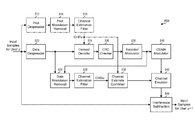
FIG. 7 shows a block diagram of an RX processor 360 c, which performs interference cancellation and is yet another exemplary embodiment of RX processor 360 in FIG. 3. RX processor 360 c includes despreaders 512 and 522, modulation removal units 514 and 534, channel estimation filters 516 and 536, combiner 538, demodulator/decoder 524, CRC checker 526, and encoder/modulator 528, which operate as described above for FIG. 6 except for the following differences. First, despreaders 512 and 522 receive input samples for terminal u. These input samples may or may not be the input samples from receiver 354 depending on whether or not terminal u is the first terminal being recovered. Second, channel estimation filter 516 (instead of combiner 538) provides a pilot-based channel estimate, CHPu, for terminal u to demodulator/decoder 524. Third, channel estimation filter 536 provides a data-based channel estimate, CHDu, for terminal u.
If a packet is decoded correctly for terminal u, then encoder/modulator 528 processes the decoded packet and provides regenerated data symbols for terminal u. A CDMA modulator 540 then spreads and scrambles the regenerated data symbols (and possibly pilot and control symbols) and generates output chips for terminal u. A channel emulator 542 receives the output chips from CDMA modulator 540 and a channel estimate from combiner 538, convolves the output chips with the channel estimate, and provides an interference estimate for terminal u. Channel emulator 542 simulates the effects of the wireless channel for terminal u. An interference subtraction unit 544 subtracts the interference estimate from the input samples for terminal u and provides input samples for the next terminal u+1.
In the exemplary embodiment shown in FIG. 7, the data-based channel estimate CHDu from filter 536 is used to derive an interference estimate for terminal u. The data-based channel estimate may also be used for demodulation and decoding for terminal u in similar manner as shown in FIG. 6. For example, whenever a packet is decoded correctly, the data-based channel estimate is derived from the regenerated data symbols for this packet and used for interference estimation for the present packet as well as demodulation/decoding for the next packet.
Combiner 538 may combine pilot-based and data-based channel estimates using any of the criteria described above for FIG. 6 and/or other criteria applicable for interference cancellation. For example, combiner 538 may provide the pilot-based channel estimate for the first stage or the first few stages. Combiner 538 may provide the data-based channel estimate or may combine the pilot-based and data-based channel estimates for the remaining stages.
FIG. 7 shows the processing for one terminal in one stage. U terminals may be processed sequentially in U stages, one terminal in each stage. The first stage processes the input samples from receiver 354 for the first terminal and provides input samples for the second stage. Each subsequent stage processes the input samples from a preceding stage for one terminal and provides input samples for the next stage.
The terminals may also be processed with parallel interference cancellation. In this case, all terminals may be processed in the first round. The interference from all terminals successfully decoded in the first round may be estimated and subtracted from the input samples. Terminals not successfully decoded in the first round may then be processed again using the interference-canceled input samples. The processing may continue until all terminals are successfully decoded or the interference from all successfully decoded terminals has been canceled. A combination of sequential and parallel interference cancellation may also be performed. In this case, the terminals may be arranged into groups, e.g., based on their SNRs. The groups may be processed sequentially, and the terminals in each group may be processed in parallel.
With interference cancellation, the SNR of each terminal is dependent on the stage/order in which the terminal is recovered. The SNR of the first terminal may be the worst since no interference has been removed. The SNR of the next terminal may be better since the interference from the first terminal has been removed. The SNR of the last terminal may be the best since the interference from all prior terminals have been removed. In general, SNR progressively improves the later a terminal is recovered.
A large variation in SNRs may be present in the symbols used to derive channel estimates. The large SNR variation may result from interference cancellation and/or from using different types of symbols, e.g., pilot symbols and data symbols, for channel estimation. The channel estimation filtering may be matched to the variation in SNRs to obtain higher quality channel estimates.
The channel estimation filters for each terminal may be selected based on the SNR for that terminal, which may be dependent on the stage/order in which the terminal is recovered as well as where within the stage the filters are used. For the first terminal with the worst SNR, channel estimation filter 516 may be for low SNR, and channel estimation filter 536 may be for low or medium SNR. For each subsequent terminal, filters 516 and 536 may be for progressively higher SNR. In general, filter 516 for successively later stages may be for progressively higher SNR. Filter 536 for successively later stages may also be for progressively higher SNR. For any given stage, filter 536 may be for higher SNR than filter 516. The particular filters to use for each stage may be appropriately selected from among all channel estimation filters available for use.
The channel estimation techniques described herein may also be used for data sent with hybrid automatic repeat request (H-ARQ). With H-ARQ, a transmitter sends one or multiple transmissions for a packet until the packet is decoded correctly by a receiver or the maximum number of transmissions has been sent for the packet. H-ARQ improves reliability for data transmission and supports rate adaptation for packets in the presence of changes in channel conditions. For a packet sent with H-ARQ, demodulator/decoder 524 may store all transmissions for the packet, combine the stored transmissions with a current transmission, and demodulate and decode the combined transmission to recover the packet. Different channel estimation filters may be used for different transmissions of a given packet, which may be associated with different SNRs.
The channel estimation techniques described herein may be used for single-input single-output (SISO), single-input multiple-output (SIMO), multiple-input single-output (MISO), and multiple-input multiple-output (MIMO) transmissions. Single-input refers to the use of a single transmit antenna, and multiple-input refers to the use of multiple transmit antennas for data transmission. Single-output refers to the use of a single receive antenna, and multiple-output refers to the use of multiple receive antennas for data reception.
FIG. 8 shows a block diagram of a transmitter 810 and a receiver 850 for MIMO transmission. For downlink transmission, transmitter 810 may be part of base station 110, and receiver 850 may be part of terminal 120. For uplink transmission, transmitter 810 may be part of terminal 120, and receiver 850 may be part of base station 110. Transmitter 110 is equipped with multiple (T) transmit antennas. Receiver 850 is equipped with multiple (R) receive antennas.
At transmitter 810, a TX data processor 820 processes data packets and generates S streams of data symbols, where 1≦S≦min {T, R}. Each packet may be sent in one stream or across multiple streams. A TX spatial processor 822 multiplexes pilot symbols with the data symbols, performs spatial mapping on the multiplexed symbols, and provides T output chip streams to T transmitters 824 a through 824 t. Each transmitter 824 processes its output chip stream and generates a modulated signal. T modulated signals from transmitters 824 a through 824 t are transmitted from antennas 826 a through 826 t, respectively.
At receiver 850, R antennas 852 a through 852 r receive the modulated signals from transmitter 810, and each antenna 852 provides a received signal to a respective receiver 854. Each receiver 854 processes its received signal and provides input samples. Within an RX processor 860, an RX spatial processor 862 performs MIMO detection on the input samples and provides detected symbols. An RX data processor 864 further processes (e.g., deinterleaves and decodes) the detected symbols and provides decoded packets.
Controllers/ processors 830 and 870 control the operation at transmitter 810 and receiver 850, respectively. Memories 832 and 872 store data and program codes for transmitter 810 and receiver 850, respectively.
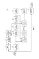
FIG. 9 shows a block diagram of an RX processor 860 a, which is an exemplary embodiment of RX processor 860 in FIG. 8. RX processor 860 a recovers the transmissions from transmitter 810 with successive interference cancellation (SIC).
For the first stage 910 a, a channel estimator 912 a derives a channel estimate CH1, e.g., based on pilot symbols. A MIMO detectors 914 a performs MIMO detection on the R streams of input samples from receivers 854 a through 854 r and provides detected symbols D1 for the first data stream being recovered. MIMO detectors 914 a may implement zero-forcing (ZF), minimum mean square error (MMSE), or some other MIMO detection scheme. A demodulator/decoder 916 a demodulates, deinterleaves and decodes the detected symbols to obtain a decoded packet and further determines whether the packet is decoded correctly or in error.
If the packet is decoded correctly, then an encoder/modulator 918 a encodes, interleaves and modulates the packet to regenerate the data symbols. A channel estimator 924 a derives a data-based channel estimate CHD1 based on the regenerated data symbols and the detected symbols D1. A combiner 926 a selectively combines the channel estimate CH1 from channel estimator 912 a and the data-based channel estimate CHD1 from channel estimator 924 a and provides a channel estimate CH2. An interference estimator 920 a estimates the interference due to the decoded packet based on the regenerated data symbols and the channel estimate CH2. An interference subtraction unit 922 a subtracts the interference estimate from the input samples and provides input samples for the next stage.
Each subsequent stage may perform processing on the input samples for that stage with the channel estimate from the prior stage, in similar manner as the first stage. Each stage provides input samples and channel estimate for the next stage.
The SNR generally improves for later stages. Different channel estimation filters may be used for channel estimators 912 and/or 924 in different stages and may be selected based on the SNRs for these stages. In general, filter 924 for successively later stages may be for progressively higher SNR. The particular filter to use for each stage may be appropriately selected from among all channel estimation filters available for use.
FIG. 10 shows an exemplary embodiment of a process 1000 for recovering a signal with a selectable channel estimation filter. A filter selection metric is determined for a signal to be recovered (block 1012). The filter selection metric may be determined based on whether pilot symbols or data symbols are used to derive a channel estimate, a traffic-to-pilot ratio for the signal, an order in which the signal is recovered among multiple signals to be recovered, an SNR of the signal, mobility, and/or other information. A channel estimation filter is selected based on the filter selection metric (block 1014). Multiple channel estimation filters with different lengths and/or frequency responses may be available, e.g., for different SNR ranges. A suitable channel estimation filter may be selected, e.g., based on the SNR explicitly or implicitly indicated by the filter selection metric. A channel estimate is derived with the selected channel estimation filter (block 1016). The signal is then recovered with the channel estimate (block 1018).
FIG. 11 shows an exemplary embodiment of a process 1100 for recovering a signal with different channel estimates. A first channel estimate is derived based on pilot symbols and with a first channel estimation filter (block 1112). A first packet is recovered with the first channel estimate (block 1114). Data symbols for the first packet are regenerated (block 1116). A second channel estimate is derived based on the data symbols and with a second channel estimation filter (block 1118). A third channel estimate is obtained based on the first and second channel estimates (block 1120). The second channel estimate may be provided as the third channel estimate, e.g., if the quality of the second channel estimate exceeds the quality of the first channel estimate by a predetermined amount, which may be determined by a traffic-to-pilot ratio. The first and second channel estimates may also be combined, with or without weighting, and provided as the third channel estimate. In any case, a second packet is recovered with the third channel estimate (block 1122).
FIG. 12 shows an exemplary embodiment of a process 1200 for recovering multiple signals. A first channel estimate is derived with a first channel estimation filter having a first filter response (block 1212). A first signal is recovered with the first channel estimate (block 1214). Interference due to the first signal is estimated (block 1216) and removed (block 1218). A second channel estimate is derived with a second channel estimation filter having a second filter response that is different from the first filter response (block 1220). A second signal is recovered with the second channel estimate (block 1222).
For block 1216, the first signal may be regenerated. A third channel estimate may be derived based on the regenerated first signal and with a third channel estimation filter having a third filter response that is different from the first filter response. A fourth channel estimate may be obtained based on the first and third channel estimates, e.g., by (1) combining the first and third channel estimates if a traffic-to-pilot ratio is within a particular range or (2) providing the first or third channel estimate as the fourth channel estimate otherwise. The interference due to the first signal may be derived with the fourth channel estimate.
Additional signals may be recovered in similar manner as the second signal. The signals may be from different transmitters, e.g., different terminals. The signals may also correspond to different data streams in a MIMO transmission.
Those of skill in the art would understand that information and signals may be represented using any of a variety of different technologies and techniques. For example, data, instructions, commands, information, signals, bits, symbols, and chips that may be referenced throughout the above description may be represented by voltages, currents, electromagnetic waves, magnetic fields or particles, optical fields or particles, or any combination thereof.
Those of skill would further appreciate that the various illustrative logical blocks, modules, circuits, and algorithm steps described in connection with the exemplary embodiments disclosed herein may be implemented as electronic hardware, computer software, or combinations of both. To clearly illustrate this interchangeability of hardware and software, various illustrative components, blocks, modules, circuits, and steps have been described above generally in terms of their functionality. Whether such functionality is implemented as hardware or software depends upon the particular application and design constraints imposed on the overall system. Skilled artisans may implement the described functionality in varying ways for each particular application, but such implementation decisions should not be interpreted as causing a departure from the scope of the present invention.
The various illustrative logical blocks, modules, and circuits described in connection with the exemplary embodiments disclosed herein may be implemented or performed with a general-purpose processor, a digital signal processor (DSP), an application specific integrated circuit (ASIC), a field programmable gate array (FPGA) or other programmable logic device, discrete gate or transistor logic, discrete hardware components, or any combination thereof designed to perform the functions described herein. A general-purpose processor may be a microprocessor, but in the alternative, the processor may be any conventional processor, controller, microcontroller, or state machine. A processor may also be implemented as a combination of computing devices, e.g., a combination of a DSP and a microprocessor, a plurality of microprocessors, one or more microprocessors in conjunction with a DSP core, or any other such configuration.
The steps of a method or algorithm described in connection with the exemplary embodiments disclosed herein may be embodied directly in hardware, in a software module executed by a processor, or in a combination of the two. A software module may reside in RAM memory, flash memory, ROM memory, EPROM memory, EEPROM memory, registers, hard disk, a removable disk, a CD-ROM, or any other form of storage medium known in the art. An exemplary storage medium is in communication with (e.g., coupled to) the processor such that the processor can read information from, and write information to, the storage medium. In the alternative, the storage medium may be integral to the processor. The processor and the storage medium may reside in an ASIC. The ASIC may reside in a user terminal. In the alternative, the processor and the storage medium may reside as discrete components in a user terminal.
The previous description of the disclosed exemplary embodiments is provided to enable any person skilled in the art to make or use the present invention. Various modifications to these exemplary embodiments will be readily apparent to those skilled in the art, and the generic principles defined herein may be applied to other exemplary embodiments without departing from the spirit or scope of the invention. Thus, the present invention is not intended to be limited to the exemplary embodiments shown herein but is to be accorded the widest scope consistent with the principles and novel features disclosed herein.

Claims (38)

What is claimed is:
1. An apparatus comprising:
means for determining a filter selection metric for a signal to be recovered, wherein the means for determining is configured to determine the filter selection metric based on whether pilot symbols, data symbols, or a combination thereof are used to derive a channel estimate, a traffic-to-pilot ratio for the signal, an order in which the signal is recovered among a plurality of signals to be recovered, a signal-to-noise ratio (SNR) of the signal, or a combination thereof;
means for selecting a channel estimation filter based on the filter selection metric, wherein the means for selecting is configured to select a first channel estimation filter when the filter selection metric indicates a first SNR within a first range of SNRs and to select a second channel estimation filter when the filter selection metric indicates a second SNR within a second range of SNRs;
means for deriving a first channel estimate with the first channel estimation filter having a first filter response;
means for recovering a first signal with the first channel estimate;
means for estimating interference due to the first signal;
means for removing the interference due to the first signal;
means for deriving a second channel estimate with the second channel estimation filter having a second filter response different from the first filter response; and
means for recovering a second signal with the second channel estimate.
2. The apparatus of claim 1, wherein the means for selecting is configured to select the channel estimation filter from among a plurality of channel estimation filters having different lengths.
3. The apparatus of claim 1, wherein the means for selecting is configured to select at least one channel estimation filter from among a plurality of channel estimation filters having different filter responses.
4. The apparatus of claim 1, wherein the filter selection metric corresponds to a packet format selected for use.
5. The apparatus of claim 1, further comprising:
means for regenerating the first signal after recovering the first signal;
means for deriving a third channel estimate based on the regenerated first signal and with a third channel estimation filter having a third filter response different from the first filter response;
means for obtaining a fourth channel estimate based on the first and third channel estimates; and
means for estimating the interference due to the first signal with the fourth channel estimate.
6. The apparatus of claim 5, wherein the means for obtaining the fourth channel estimate comprises:
means for combining the first and third channel estimates to obtain the fourth channel estimate when a traffic to pilot ratio is within a particular range; and
means for providing the first channel estimate or the third channel estimate as the fourth channel estimate when the traffic to pilot ratio is outside the particular range.
7. The apparatus of claim 1, wherein the apparatus is configured to:
estimate interference due to the second signal;
remove the interference due to the second signal;
derive a third channel estimate with a third channel estimation filter having a third filter response different from the first filter response; and
recover a third signal with the third channel estimate.
8. The apparatus of claim 1, wherein the first and second signals are from two terminals.
9. The apparatus of claim 1, wherein the first and second signals are for a multiple-input multiple-output (MIMO) transmission.
10. A method comprising:
determining, at a mobile communication device, a filter selection metric for a signal to be recovered, wherein the filter selection metric is determined based on whether pilot symbols, data symbols, or a combination thereof are used to derive a channel estimate, a traffic-to-pilot ratio for the signal, an order in which the signal is recovered among a plurality of signals to be recovered, a signal-to-noise ratio (SNR) of the signal, or a combination thereof;
selecting, at the mobile communication device, a channel estimation filter based on the filter selection metric, wherein the selecting is performed so as to select a first channel estimation filter when the filter selection metric indicates a first SNR within a first range of SNRs and to select a second channel estimation filter when the filter selection metric indicates a second SNR within a second range of SNRs;
deriving, at the mobile communication device, a first channel estimate with the first channel estimation filter having a first filter response;
recovering, at the mobile communication device, a first signal with the first channel estimate;
estimating, at the mobile communication device, interference due to the first signal;
removing, at the mobile communication device, the interference due to the first signal;
deriving, at the mobile communication device, a second channel estimate with the second channel estimation filter having a second filter response different from the first filter response; and
recovering, at the mobile communication device, a second signal with the second channel estimate.
11. The method of claim 10, wherein the channel estimation filter is selected from among a plurality of channel estimation filters having different lengths.
12. The method of claim 10, wherein the channel estimation filter is selected from among a plurality of channel estimation filters having different filter responses.
13. The method of claim 10, wherein the filter selection metric corresponds to a packet format selected for use.
14. The method of claim 10, further comprising:
regenerating, at the mobile communication device, the first signal after recovering the first signal;
deriving, at the mobile communication device, a third channel estimate based on the regenerated first signal and with a third channel estimation filter having a third filter response different from the first filter response;
obtaining, at the mobile communication device, a fourth channel estimate based on the first and third channel estimates; and
estimating, at the mobile communication device, the interference due to the first signal with the fourth channel estimate.
15. The method of claim 14, wherein obtaining the fourth channel estimate comprises:
combining the first and third channel estimates to obtain the fourth channel estimate when a traffic to pilot ratio is within a particular range; and
providing the first channel estimate or the third channel estimate as the fourth channel estimate when the traffic to pilot ratio is outside the particular range.
16. The method of claim 13, further comprising:
estimating, at the mobile communication device, interference due to the second signal;
removing, at the mobile communication device, the interference due to the second signal;
deriving, at the mobile communication device, a third channel estimate with a third channel estimation filter having a third filter response different from the first filter response; and
recovering, at the mobile communication device, a third signal with the third channel estimate.
17. The method of claim 13, wherein the first and second signals are from two terminals.
18. The method of claim 13, wherein the first and second signals are for a multiple-input multiple-output (MIMO) transmission.
19. A non-transitory computer readable storage medium comprising processor executable instructions that, when executed by a processor, cause the processor to:
determine a filter selection metric for a signal to be recovered, wherein the filter selection metric is determined based on whether pilot symbols, data symbols, or a combination thereof are used to derive a channel estimate, a traffic-to-pilot ratio for the signal, an order in which the signal is recovered among a plurality of signals to be recovered, a signal-to-noise ratio (SNR) of the signal, or a combination thereof;
select a channel estimation filter based on the filter selection metric, wherein the channel estimation filter is selected so as to select a first channel estimation filter when the filter selection metric indicates a first SNR within a first range of SNRs and to select a second channel estimation filter when the filter selection metric indicates a second SNR within a second range of SNRs;
derive a first channel estimate with the first channel estimation filter having a first filter response;
recover a first signal with the first channel estimate;
estimate interference due to the first signal;
remove the interference due to the first signal;
derive a second channel estimate with the second channel estimation filter having a second filter response different from the first filter response; and
recover a second signal with the second channel estimate.
20. The non-transitory computer readable storage medium of claim 19, wherein the channel estimation filter is selected from among a plurality of channel estimation filters having different lengths.
21. The non-transitory computer readable storage medium of claim 19, wherein the channel estimation filter is selected from among a plurality of channel estimation filters having different filter responses.
22. The non-transitory computer readable storage medium of claim 19, wherein the filter selection metric corresponds to a packet format selected for use.
23. The non-transitory computer readable storage medium of claim 22, further comprising processor executable instructions that, when executed by the processor, cause the processor to:
regenerate the first signal after recovering the first signal;
derive a third channel estimate based on the regenerated first signal and with a third channel estimation filter having a third filter response different from the first filter response;
obtain a fourth channel estimate based on the first and third channel estimates; and
estimate the interference due to the first signal with the fourth channel estimate.
24. The non-transitory computer readable storage medium of claim 23, wherein the fourth channel estimate is obtained by:
combining the first and third channel estimates to obtain the fourth channel estimate when a traffic to pilot ratio is within a particular range; and
providing the first channel estimate or the third channel estimate as the fourth channel estimate when the traffic to pilot ratio is outside the particular range.
25. The non-transitory computer readable storage medium of claim 22, further comprising processor executable instructions that, when executed by the processor, cause the processor to:
estimate interference due to the second signal;
remove the interference due to the second signal;
derive a third channel estimate with a third channel estimation filter having a third filter response different from the first filter response; and
recover a third signal with the third channel estimate.
26. The computer readable medium of claim 22, wherein the first and second signals are from two terminals.
27. The computer readable medium of claim 22, wherein the first and second signals are for a multiple-input multiple-output (MIMO) transmission.
28. An apparatus comprising:
means for determining a filter selection metric for a signal to be recovered, wherein the means for determining is configured to determine the filter selection metric based on whether pilot symbols, data symbols, or a combination thereof are used to derive a channel estimate, a traffic-to-pilot ratio for the signal, an order in which the signal is recovered among a plurality of signals to be recovered, a signal-to-noise ratio (SNR) of the signal, or a combination thereof and wherein the filter selection metric corresponds to a packet format;
means for selecting a channel estimation filter based on the filter selection metric, wherein the means for selecting is configured to select a first channel estimation filter when the filter selection metric indicates a first SNR within a first range of SNRs and to select a second channel estimation filter when the filter selection metric indicates a second SNR within a second range of SNRs; and
means for deriving a first channel estimate with a first channel estimation filter having a first filter response;
means for recovering a first signal with the first channel estimate;
means for estimating interference due to the first signal;
means for removing the interference due to the first signal;
means for deriving a second channel estimate with a second channel estimation filter having a second filter response different from the first filter response; and
means for recovering a second signal with the second channel estimate.
29. The apparatus of claim 28, wherein the means for selecting is configured to select the channel estimation filter from among a plurality of channel estimation filters having different lengths.
30. The apparatus of claim 28, wherein the means for selecting is configured to select the channel estimation filter from among a plurality of channel estimation filters having different filter responses.
31. The apparatus of claim 30, further comprising:
means for regenerating the first signal after recovering the first signal;
means for deriving a third channel estimate based on the regenerated first signal and with a third channel estimation filter having a third filter response different from the first filter response;
means for obtaining a fourth channel estimate based on the first and third channel estimates; and
means for estimating the interference due to the first signal with the fourth channel estimate.
32. The apparatus of claim 31, wherein the means for obtaining comprises:
means for combining the first and third channel estimates to obtain the fourth channel estimate when a traffic to pilot ratio is within a particular range; and
means for providing the first channel estimate or the third channel estimate as the fourth channel estimate when the traffic to pilot ratio is outside the particular range.
33. The apparatus of claim 30, further comprising:
means for estimating interference due to the second signal;
means for removing the interference due to the second signal;
means for deriving a third channel estimate with a third channel estimation filter having a third filter response different from the first filter response; and
means for recovering a third signal with the third channel estimate.
34. The apparatus of claim 30, wherein the first and second signals are from two terminals.
35. The apparatus of claim 30, wherein the first and second signals are for a multiple-input multiple-output (MIMO) transmission.
36. An apparatus comprising:
a processor; and
a memory storing instructions executable by the processor to:
determine a filter selection metric for a signal to be recovered, wherein the filter selection metric is determined based on whether pilot symbols, data symbols, or a combination thereof are used to derive a channel estimate, a traffic-to-pilot ratio for the signal, an order in which the signal is recovered among a plurality of signals to be recovered, a signal-to-noise ratio (SNR) of the signal, or a combination thereof;
select a channel estimation filter based on the filter selection metric, wherein the channel estimation filter is selected so as to select a first channel estimation filter when the filter selection metric indicates a first SNR within a first range of SNRs and to select a second channel estimation filter when the filter selection metric indicates a second SNR within a second range of SNRs;
derive a first channel estimate with the first channel estimation filter having a first filter response;
recover a first signal with the first channel estimate;
estimate interference due to the first signal;
remove the interference due to the first signal;
derive a second channel estimate with the second channel estimation filter having a second filter response different from the first filter response; and
recover a second signal with the second channel estimate.
37. The method of claim 10, wherein the mobile communication device is a base station.
38. The method of claim 10, wherein the mobile communication device is a user equipment.
US12/717,598 2005-08-12 2010-03-04 Channel estimation for wireless communication Active 2028-01-14 US8625656B2 (en)

Priority Applications (1)

Application Number Priority Date Filing Date Title
US12/717,598 US8625656B2 (en) 2005-08-12 2010-03-04 Channel estimation for wireless communication

Applications Claiming Priority (3)

Application Number Priority Date Filing Date Title
US70767305P 2005-08-12 2005-08-12
US11/492,605 US8165186B2 (en) 2005-08-12 2006-07-24 Channel estimation for wireless communication
US12/717,598 US8625656B2 (en) 2005-08-12 2010-03-04 Channel estimation for wireless communication

Related Parent Applications (1)

Application Number Title Priority Date Filing Date
US11/492,605 Continuation US8165186B2 (en) 2005-08-12 2006-07-24 Channel estimation for wireless communication

Publications (2)

Publication Number Publication Date
US20100158176A1 US20100158176A1 (en) 2010-06-24
US8625656B2 true US8625656B2 (en) 2014-01-07

Family

ID=37499233

Family Applications (3)

Application Number Title Priority Date Filing Date
US11/492,605 Active 2029-03-09 US8165186B2 (en) 2005-08-12 2006-07-24 Channel estimation for wireless communication
US12/717,598 Active 2028-01-14 US8625656B2 (en) 2005-08-12 2010-03-04 Channel estimation for wireless communication
US12/902,992 Active 2027-02-22 US8437380B2 (en) 2005-08-12 2010-10-12 Channel estimation for wireless communication

Family Applications Before (1)

Application Number Title Priority Date Filing Date
US11/492,605 Active 2029-03-09 US8165186B2 (en) 2005-08-12 2006-07-24 Channel estimation for wireless communication

Family Applications After (1)

Application Number Title Priority Date Filing Date
US12/902,992 Active 2027-02-22 US8437380B2 (en) 2005-08-12 2010-10-12 Channel estimation for wireless communication

Country Status (10)

Country Link
US (3) US8165186B2 (en)
EP (3) EP1913745B1 (en)
JP (3) JP4897810B2 (en)
KR (3) KR101185876B1 (en)
CN (3) CN101283559B (en)
AT (1) ATE532301T1 (en)
ES (1) ES2373567T3 (en)
MY (1) MY146679A (en)
TW (2) TW201036363A (en)
WO (1) WO2007021952A2 (en)

Cited By (2)

* Cited by examiner, † Cited by third party
Publication number Priority date Publication date Assignee Title
US20130121393A1 (en) * 2011-11-10 2013-05-16 Marvell World Trade Ltd. Channel estimation with decision feedback
US9350587B1 (en) 2012-11-30 2016-05-24 Marvell International Ltd. System and method for timing error estimation

Families Citing this family (46)

* Cited by examiner, † Cited by third party
Publication number Priority date Publication date Assignee Title
WO2005015775A1 (en) * 2003-08-11 2005-02-17 Nortel Networks Limited System and method for embedding ofdm in cdma systems
US8165186B2 (en) * 2005-08-12 2012-04-24 Qualcomm Incorporated Channel estimation for wireless communication
US7864885B2 (en) * 2006-11-15 2011-01-04 Samsung Electronics Co., Ltd. Multiple input multiple output (MIMO) transceiver with pooled adaptive digital filtering
US8102795B2 (en) * 2007-03-09 2012-01-24 Qualcomm Incorporated Channel equalization with non-common midamble allocation in 3GPP TD-CDMA systems
US8014424B2 (en) * 2007-06-25 2011-09-06 Qualcomm Incorporated Method and apparatus for using an unique index set for PSC sequence in a wireless communication system
EP2062374A4 (en) * 2007-08-31 2014-12-03 Fujitsu Ltd Wireless communication system and wireless communication method
KR101457690B1 (en) * 2008-03-05 2014-11-04 삼성전자주식회사 Apparatus and method for remoiving interference signal in a communication system
KR101402906B1 (en) * 2008-06-23 2014-06-02 삼성전자주식회사 Apparatus and method for power control in mobile communication system
US8428538B2 (en) * 2008-07-09 2013-04-23 Intel Mobile Communications GmbH Channel estimator
US8238482B2 (en) 2008-10-14 2012-08-07 Apple Inc. Techniques for improving channel estimation and tracking in a wireless communication system
KR101556636B1 (en) * 2008-12-16 2015-10-01 삼성전자주식회사 Method and apparatus for estimating channel using data channel
US8830918B2 (en) 2009-03-16 2014-09-09 Interdigital Patent Holdings, Inc. Method and apparatus for performing uplink transmit diversity
US8615030B2 (en) * 2009-05-04 2013-12-24 Qualcomm Incorporated Method and system for multi-user detection using two-stage processing
US8451963B2 (en) * 2009-06-09 2013-05-28 Qualcomm Incorporated Method and system for interference cancellation
WO2011007258A2 (en) 2009-07-15 2011-01-20 Nortel Networks Limited Selecting from among plural channel estimation techniques
US9256560B2 (en) * 2009-07-29 2016-02-09 Solarflare Communications, Inc. Controller integration
US8509287B2 (en) * 2009-10-23 2013-08-13 Broadcom Corporation Method and system for diversity processing utilizing a programmable interface suppression module
US8335286B2 (en) * 2009-08-26 2012-12-18 Qualcomm Incorporated Methods for determining decoding order in a MIMO system with successive interference cancellation
US8594238B2 (en) 2009-12-15 2013-11-26 Electronics And Telecommunications Research Institute Apparatus and method for estimating channel in channel domain
KR101329335B1 (en) * 2009-12-15 2013-11-20 한국전자통신연구원 Apparatus and method for estimating of channel in frequency domain
US8699553B2 (en) 2010-02-19 2014-04-15 Telefonaktiebolaget Lm Ericsson (Publ) Data-aided SIR estimation
US8396168B2 (en) * 2010-04-15 2013-03-12 Telefonaktiebolaget L M Ericsson (Publ) Channel estimation for equalizer using serial localization with indecision
US8699592B1 (en) 2010-06-11 2014-04-15 Marvell International Ltd. Systems and methods for estimating decoder noise power in OFDM systems
WO2012109529A1 (en) 2011-02-11 2012-08-16 Interdigital Patent Holdings, Inc. Method and apparatus for uplink closed loop transmit diversity transmission initial access
US9313744B2 (en) * 2011-10-28 2016-04-12 Qualcomm Incorporated Method and apparatus for configuring traffic-to-pilot power ratios in heterogeneous networks
TWI491227B (en) 2012-07-23 2015-07-01 Apple Inc Methods and systems for anchored down-selection in a coordinated multipoint transmission cluster
US8737457B2 (en) * 2012-09-28 2014-05-27 Telefonaktiebolaget L M Ericsson (Publ) Adaptive smoothing of channel estimates
US9485061B2 (en) * 2012-10-12 2016-11-01 Samsung Electronics Co., Ltd. Communication system with flexible repeat-response mechanism and method of operation thereof
EP2782282A3 (en) 2013-03-20 2018-04-04 ZTE (USA) Inc. Soft maximum likelihood sequence estimation in digital communication
EP2782305B1 (en) 2013-03-20 2019-07-24 ZTE (USA) Inc. Statistics adaptive soft decision forward error correction in digital communication
US9553706B2 (en) * 2013-05-15 2017-01-24 Qualcomm Incorporated Channel estimate under non-uniform reference signal pattern
US20150049731A1 (en) * 2013-08-16 2015-02-19 Mitsubishi Electric Research Laboratories, Inc. Method for Coding OFDMA Data without Pilot Symbols
WO2015050421A1 (en) * 2013-10-04 2015-04-09 삼성전자 주식회사 Method and device for estimating channel in wireless communication system
US9350590B2 (en) * 2013-10-25 2016-05-24 Texas Instruments Incorporated Method, system and apparatus for carrier frequency offset correction and channel estimation
EP2975787B1 (en) * 2014-07-16 2018-10-03 ZTE Corporation Adaptive post digital filter and inter-symbol interference equalizer for optical communication
EP3007394B1 (en) 2014-10-07 2019-07-03 ZTE Corporation Maximum likelihood sequence estimation of quadrature amplitude modulated signals
WO2017019002A1 (en) * 2015-07-24 2017-02-02 Halliburton Energy Services, Inc. Channel estimation in mud pulse telemetry
JP6538589B2 (en) * 2016-02-26 2019-07-03 日本電信電話株式会社 Wireless communication apparatus and interference reduction method
KR101943984B1 (en) 2017-02-13 2019-01-31 전남대학교산학협력단 Method for channel interpolation based on the lte sidelink system and apparatus for thereof
KR101943985B1 (en) 2017-02-14 2019-01-31 전남대학교산학협력단 Method for channel estimation based of lte and apparatus for thereof
KR101977623B1 (en) 2017-06-30 2019-05-14 전남대학교산학협력단 Interpolation and prediction method for fast link adaptation, and apparatus thereof
KR101940749B1 (en) 2017-08-21 2019-01-22 전남대학교산학협력단 Method for channel estimation and apparatus for thereof
KR101943983B1 (en) 2017-08-22 2019-01-31 전남대학교산학협력단 Method and apparatus for estimating channel in v2v communication
US20220376957A1 (en) * 2019-09-19 2022-11-24 Nokia Solution and Networka Oy Machine Learning-Based Channel Estimation
WO2023287415A1 (en) * 2021-07-14 2023-01-19 Zeku, Inc. Apparatus and method for low power channel estimation
CN113436648B (en) * 2021-08-26 2021-11-30 深圳市志泽科技有限公司 Bidirectional communication system with transmission channel selection function

Citations (26)

* Cited by examiner, † Cited by third party
Publication number Priority date Publication date Assignee Title
WO1995020842A1 (en) 1994-01-27 1995-08-03 Ericsson Ge Mobile Communications Inc. Method and system for demodulation of downlink cdma signals
EP0813314A2 (en) 1996-06-10 1997-12-17 Nec Corporation Direct-sequence code division multiple access receiver
US5872816A (en) 1996-08-20 1999-02-16 Hughes Electronics Corporation Coherent blind demodulation
WO1999060721A1 (en) 1998-05-15 1999-11-25 Ericsson Inc. Method for improving signal reception in a mobile communication unit by using pilot symbols
EP0967734A2 (en) 1998-06-25 1999-12-29 Nec Corporation Multiuser interference canceler for DS-cdma system
EP0986204A1 (en) 1998-02-27 2000-03-15 Matsushita Electric Industrial Co., Ltd. Method and apparatus for interference rejection
WO2000064067A1 (en) 1999-04-15 2000-10-26 Ericsson Inc. Method and apparatus for successive cancellation using multiple signal timings
WO2001022571A1 (en) 1999-09-17 2001-03-29 Telefonaktiebolaget Lm Ericsson (Publ) Apparatus and method for substantially eliminating a near-channel interfering amplitude modulated signal
WO2001039032A1 (en) 1999-11-11 2001-05-31 Voyan Technology Method for design and implementation of fixed-point filters for control and signal processing
EP1122891A1 (en) 2000-01-31 2001-08-08 Telefonaktiebolaget Lm Ericsson Radio receiver and method therein
EP1124346A1 (en) 1999-08-24 2001-08-16 Matsushita Electric Industrial Co., Ltd. Method and apparatus for radio reception
JP2001326586A (en) 2000-05-17 2001-11-22 Nec Corp Cdma communication system and channel estimate method used for it
JP2002044172A (en) 2000-07-26 2002-02-08 Sanyo Electric Co Ltd Phase correction circuit and mobile radio terminal provided with the phase correction circuit
EP1211819A1 (en) 2000-07-26 2002-06-05 Matsushita Electric Industrial Co., Ltd. Radio receiving device and radio receiving method
US6414988B1 (en) 1999-05-12 2002-07-02 Qualcomm Incorporated Amplitude and phase estimation method in a wireless communication system
EP1229668A2 (en) 2001-01-31 2002-08-07 NTT DoCoMo, Inc. Receiving process method and receiving apparatus in mobile communication system
WO2003015296A1 (en) 2001-08-07 2003-02-20 Intersil Americas Inc. Intelligent control system and method for a wireless communications system
US20030072277A1 (en) 2001-08-07 2003-04-17 Parvathanathan Subrahmanya Adaptive pilot filter for a wireless communication system
EP1401164A1 (en) 2002-09-19 2004-03-24 Telefonaktiebolaget Lm Ericsson Bandwith estimation and adaptive filtering
WO2004082172A1 (en) 2003-03-10 2004-09-23 Samsung Electronics Co. Ltd. Apparatus and method for estimating a velocity of a mobile station in a mobile communication system
GB2403113A (en) 2002-08-16 2004-12-22 Toshiba Res Europ Ltd Estimation of one of a plurality of channels using identification data
WO2005048546A2 (en) 2003-11-13 2005-05-26 Telefonaktiebolaget Lm Ericsson (Publ) Channel estimation by adaptive interpolation
US6963546B2 (en) 2000-03-15 2005-11-08 Interdigital Technology Corp. Multi-user detection using an adaptive combination of joint detection and successive interface cancellation
US7035659B1 (en) 2001-10-22 2006-04-25 Via Telecom Co., Ltd. Estimation of forward link signal-to-noise ratio
US7133435B2 (en) 2001-06-20 2006-11-07 Texas Instruments Incorporated Interference cancellation system and method
WO2007021952A2 (en) 2005-08-12 2007-02-22 Qualcomm Incorporated Channel estimation for wireless communication

Family Cites Families (6)

* Cited by examiner, † Cited by third party
Publication number Priority date Publication date Assignee Title
US4740236A (en) * 1982-12-03 1988-04-26 Ciba-Geigy Corporation N-sulfonyl-imino-thiocarbonic acid diesters as herbicide antagonists for the protection of rice crops
JP3369489B2 (en) * 1998-11-11 2003-01-20 松下電器産業株式会社 Wireless communication device and wireless communication method
JP2002043980A (en) * 2000-07-24 2002-02-08 Matsushita Electric Ind Co Ltd Wireless receiving device and wireless receiving method
DE10228103A1 (en) 2002-06-24 2004-01-15 Bayer Cropscience Ag Fungicidal active ingredient combinations
JP2004120643A (en) * 2002-09-27 2004-04-15 Toshiba Corp Rake receiver and receiving control program of the same
US7092731B2 (en) * 2003-03-06 2006-08-15 Lucent Technologies Inc. Method for improving capacity of a reverse link channel in a wireless network

Patent Citations (42)

* Cited by examiner, † Cited by third party
Publication number Priority date Publication date Assignee Title
WO1995020842A1 (en) 1994-01-27 1995-08-03 Ericsson Ge Mobile Communications Inc. Method and system for demodulation of downlink cdma signals
EP0813314A2 (en) 1996-06-10 1997-12-17 Nec Corporation Direct-sequence code division multiple access receiver
US5872816A (en) 1996-08-20 1999-02-16 Hughes Electronics Corporation Coherent blind demodulation
EP0986204A1 (en) 1998-02-27 2000-03-15 Matsushita Electric Industrial Co., Ltd. Method and apparatus for interference rejection
WO1999060721A1 (en) 1998-05-15 1999-11-25 Ericsson Inc. Method for improving signal reception in a mobile communication unit by using pilot symbols
EP0967734A2 (en) 1998-06-25 1999-12-29 Nec Corporation Multiuser interference canceler for DS-cdma system
WO2000064067A1 (en) 1999-04-15 2000-10-26 Ericsson Inc. Method and apparatus for successive cancellation using multiple signal timings
US6414988B1 (en) 1999-05-12 2002-07-02 Qualcomm Incorporated Amplitude and phase estimation method in a wireless communication system
EP1124346A1 (en) 1999-08-24 2001-08-16 Matsushita Electric Industrial Co., Ltd. Method and apparatus for radio reception
CN1319289A (en) 1999-08-24 2001-10-24 松下电器产业株式会社 Method and apparatus for radio reception
WO2001022571A1 (en) 1999-09-17 2001-03-29 Telefonaktiebolaget Lm Ericsson (Publ) Apparatus and method for substantially eliminating a near-channel interfering amplitude modulated signal
JP2003510873A (en) 1999-09-17 2003-03-18 テレフオンアクチーボラゲット エル エム エリクソン(パブル) Apparatus and method for sufficiently removing amplitude modulated adjacent channel interference signal
WO2001039032A1 (en) 1999-11-11 2001-05-31 Voyan Technology Method for design and implementation of fixed-point filters for control and signal processing
EP1122891A1 (en) 2000-01-31 2001-08-08 Telefonaktiebolaget Lm Ericsson Radio receiver and method therein
US6963546B2 (en) 2000-03-15 2005-11-08 Interdigital Technology Corp. Multi-user detection using an adaptive combination of joint detection and successive interface cancellation
JP2001326586A (en) 2000-05-17 2001-11-22 Nec Corp Cdma communication system and channel estimate method used for it
US6937642B2 (en) 2000-05-17 2005-08-30 Nec Corporation CDMA communication system and channel estimating method used in the same
EP1211819A1 (en) 2000-07-26 2002-06-05 Matsushita Electric Industrial Co., Ltd. Radio receiving device and radio receiving method
US20020164967A1 (en) 2000-07-26 2002-11-07 Kenichi Miyoshi Radio receiving device and radio receiving method
JP2002044172A (en) 2000-07-26 2002-02-08 Sanyo Electric Co Ltd Phase correction circuit and mobile radio terminal provided with the phase correction circuit
US6993308B2 (en) * 2000-07-26 2006-01-31 Matsushita Electric Industrial Co., Ltd. Radio receiving device and radio receiving method
EP1229668A2 (en) 2001-01-31 2002-08-07 NTT DoCoMo, Inc. Receiving process method and receiving apparatus in mobile communication system
US20030142655A1 (en) 2001-01-31 2003-07-31 Ntt Docomo, Inc. Receiving process method and receiving apparatus in mobile communication system
US7133435B2 (en) 2001-06-20 2006-11-07 Texas Instruments Incorporated Interference cancellation system and method
JP2004538707A (en) 2001-08-07 2004-12-24 インターシル アメリカス インコーポレイテッド Intelligent control system and method for wireless communication system
US7058144B2 (en) * 2001-08-07 2006-06-06 Conexant, Inc. Intelligent control system and method for compensation application in a wireless communications system
JP2004538720A (en) 2001-08-07 2004-12-24 クゥアルコム・インコーポレイテッド Adaptive selection of pilot filters for wireless communication systems
US7230975B2 (en) * 2001-08-07 2007-06-12 Qualcomm Incorporated Adaptive pilot filter for a wireless communication system
WO2003015296A1 (en) 2001-08-07 2003-02-20 Intersil Americas Inc. Intelligent control system and method for a wireless communications system
US20030072277A1 (en) 2001-08-07 2003-04-17 Parvathanathan Subrahmanya Adaptive pilot filter for a wireless communication system
US20030058962A1 (en) 2001-08-07 2003-03-27 Baldwin Keith R. Intelligent control system and method for compensation application in a wireless communications system
US7035659B1 (en) 2001-10-22 2006-04-25 Via Telecom Co., Ltd. Estimation of forward link signal-to-noise ratio
GB2403113A (en) 2002-08-16 2004-12-22 Toshiba Res Europ Ltd Estimation of one of a plurality of channels using identification data
EP1401164A1 (en) 2002-09-19 2004-03-24 Telefonaktiebolaget Lm Ericsson Bandwith estimation and adaptive filtering
WO2004082172A1 (en) 2003-03-10 2004-09-23 Samsung Electronics Co. Ltd. Apparatus and method for estimating a velocity of a mobile station in a mobile communication system
WO2005048546A2 (en) 2003-11-13 2005-05-26 Telefonaktiebolaget Lm Ericsson (Publ) Channel estimation by adaptive interpolation
WO2007021952A2 (en) 2005-08-12 2007-02-22 Qualcomm Incorporated Channel estimation for wireless communication
US20110026653A1 (en) 2005-08-12 2011-02-03 Qualcomm Incorporated Channel estimation for wireless communication
JP2012034412A (en) 2005-08-12 2012-02-16 Qualcomm Inc Channel estimation for wireless communication
JP2012034413A (en) 2005-08-12 2012-02-16 Qualcomm Inc Channel estimation for wireless communication
JP4897810B2 (en) 2005-08-12 2012-03-14 クゥアルコム・インコーポレイテッド Channel estimation for wireless communication
US8165186B2 (en) * 2005-08-12 2012-04-24 Qualcomm Incorporated Channel estimation for wireless communication

Non-Patent Citations (12)

* Cited by examiner, † Cited by third party
Title
3GPP TR 25.896 v6.0.0 (Mar. 2004), 3rd Generation Partnership Project; Technical Specification Group Radio Access Network; Feasibility Study for Enhanced Uplink for UTRA FDD (Release 6).
3GPP TS 25.213 v6.3.0 (Jun. 2005), 3rd Generation Partnership Project; Technical Specification Group Radio Access Network; Spreading and modulation (FDD) (Release 6).
European Search Report-EP10004137, Search Authority-The Hague Patent Office, Apr. 8, 2010.
European Search Report-EP10014083-Search Authority-Munich-Jan. 24, 2013.
Higuchi, et al., "Experimental evaluation of combined effect of coherent RAKE combining and SIR-based fast transmit power control for reverse link of DS-CDMA mobile radio," IEEE Journal on Selected Areas in Communications, vol. 18, Issue 8, Aug. 2000, pp. 1526-1535.
International Preliminary Report on Patentability-PCT/US06/031405, International Bureau of WIPO-Geneva, Switzerland, Feb. 12, 2008.
International Search Report-PCT/US06/031405, International Search Authority-European Patent Office, Feb. 16, 2007.
Patel, et al., "Analysis of a simple successive interference cancellation scheme in a DS/CDMA system," IEEE Journal on Selected Areas in Communications, vol. 12, Issue 5, Jun. 1994, pp. 796-807.
Taiwan Search Report-TW099116720-TIPO-Apr. 2, 2013.
Taiwanese Search Report-095129608-TIPO-Sep. 4, 2009.
Viterbi, "Very low rate convolutional codes for maximum theoretical performance of spread-spectrum multiple-access channels," IEEE Journal on Selected Areas in Communications, vol. 8, Issue 4, May 1990, pp. 641-649.
Written Opinion-PCT/US06/031405, International Search Authority-European Patent Office, Feb. 16, 2007.

Cited By (3)

* Cited by examiner, † Cited by third party
Publication number Priority date Publication date Assignee Title
US20130121393A1 (en) * 2011-11-10 2013-05-16 Marvell World Trade Ltd. Channel estimation with decision feedback
US8903001B2 (en) * 2011-11-10 2014-12-02 Marvell World Trade Ltd. Channel estimation with decision feedback
US9350587B1 (en) 2012-11-30 2016-05-24 Marvell International Ltd. System and method for timing error estimation

Also Published As

Publication number Publication date
EP2273742B1 (en) 2019-10-16
KR20100110398A (en) 2010-10-12
KR20100008010A (en) 2010-01-22
KR101143242B1 (en) 2012-05-21
ATE532301T1 (en) 2011-11-15
EP1913745A2 (en) 2008-04-23
EP2226949A1 (en) 2010-09-08
US20100158176A1 (en) 2010-06-24
TW200718080A (en) 2007-05-01
CN101958730A (en) 2011-01-26
WO2007021952A2 (en) 2007-02-22
WO2007021952A3 (en) 2007-04-12
KR101185876B1 (en) 2012-09-26
CN101283559A (en) 2008-10-08
KR20080033543A (en) 2008-04-16
EP2273742A2 (en) 2011-01-12
TW201036363A (en) 2010-10-01
US20110026653A1 (en) 2011-02-03
US20070104253A1 (en) 2007-05-10
CN101283559B (en) 2015-02-18
CN101977168B (en) 2014-04-09
JP5442696B2 (en) 2014-03-12
EP1913745B1 (en) 2011-11-02
JP5442697B2 (en) 2014-03-12
JP2012034412A (en) 2012-02-16
EP2226949B1 (en) 2020-10-21
MY146679A (en) 2012-09-14
CN101958730B (en) 2013-02-13
KR101096889B1 (en) 2011-12-22
EP2273742A3 (en) 2013-03-06
US8437380B2 (en) 2013-05-07
JP2012034413A (en) 2012-02-16
TWI340568B (en) 2011-04-11
ES2373567T3 (en) 2012-02-06
JP4897810B2 (en) 2012-03-14
JP2009505510A (en) 2009-02-05
US8165186B2 (en) 2012-04-24
CN101977168A (en) 2011-02-16

Similar Documents

Publication Publication Date Title
US8625656B2 (en) Channel estimation for wireless communication
US8385388B2 (en) Method and system for signal reconstruction from spatially and temporally correlated received samples
EP1941624B1 (en) System and method for iterative multipath interference cancellation
US8385477B2 (en) Decision boundary estimation for MIMO wireless receivers
EP1872484A2 (en) Method and apparatus for canceling interference from high power, high data rate signals
US20100067563A1 (en) Method and system of communications
EP1372308B1 (en) Method and apparatus for decision directed channel equalization in spread spectrum receivers

Legal Events

Date Code Title Description
AS Assignment

Owner name: QUALCOMM INCORPORATED,CALIFORNIA

Free format text: ASSIGNMENT OF ASSIGNORS INTEREST;ASSIGNORS:LUO, TAO;DAMNJANOVIC, ALEKSANDAR;MALLADI, DURGA PRASAD;SIGNING DATES FROM 20061211 TO 20061213;REEL/FRAME:024155/0143

Owner name: QUALCOMM INCORPORATED, CALIFORNIA

Free format text: ASSIGNMENT OF ASSIGNORS INTEREST;ASSIGNORS:LUO, TAO;DAMNJANOVIC, ALEKSANDAR;MALLADI, DURGA PRASAD;SIGNING DATES FROM 20061211 TO 20061213;REEL/FRAME:024155/0143

STCF Information on status: patent grant

Free format text: PATENTED CASE

FPAY Fee payment

Year of fee payment: 4

MAFP Maintenance fee payment

Free format text: PAYMENT OF MAINTENANCE FEE, 8TH YEAR, LARGE ENTITY (ORIGINAL EVENT CODE: M1552); ENTITY STATUS OF PATENT OWNER: LARGE ENTITY

Year of fee payment: 8