CN101977168B - Channel estimation for wireless communication - Google Patents
Channel estimation for wireless communication Download PDFInfo
- Publication number
- CN101977168B CN101977168B CN201010521845.7A CN201010521845A CN101977168B CN 101977168 B CN101977168 B CN 101977168B CN 201010521845 A CN201010521845 A CN 201010521845A CN 101977168 B CN101977168 B CN 101977168B
- Authority
- CN
- China
- Prior art keywords
- channel estimation
- signal
- channel
- estimation value
- filter
- Prior art date
- Legal status (The legal status is an assumption and is not a legal conclusion. Google has not performed a legal analysis and makes no representation as to the accuracy of the status listed.)
- Active
Links
Images


Classifications
-
- H—ELECTRICITY
- H04—ELECTRIC COMMUNICATION TECHNIQUE
- H04L—TRANSMISSION OF DIGITAL INFORMATION, e.g. TELEGRAPHIC COMMUNICATION
- H04L25/00—Baseband systems
- H04L25/02—Details ; arrangements for supplying electrical power along data transmission lines
- H04L25/0202—Channel estimation
-
- H—ELECTRICITY
- H04—ELECTRIC COMMUNICATION TECHNIQUE
- H04B—TRANSMISSION
- H04B1/00—Details of transmission systems, not covered by a single one of groups H04B3/00 - H04B13/00; Details of transmission systems not characterised by the medium used for transmission
- H04B1/69—Spread spectrum techniques
- H04B1/707—Spread spectrum techniques using direct sequence modulation
- H04B1/7097—Interference-related aspects
- H04B1/7103—Interference-related aspects the interference being multiple access interference
- H04B1/7107—Subtractive interference cancellation
- H04B1/71072—Successive interference cancellation
-
- H—ELECTRICITY
- H04—ELECTRIC COMMUNICATION TECHNIQUE
- H04B—TRANSMISSION
- H04B7/00—Radio transmission systems, i.e. using radiation field
- H04B7/02—Diversity systems; Multi-antenna system, i.e. transmission or reception using multiple antennas
- H04B7/04—Diversity systems; Multi-antenna system, i.e. transmission or reception using multiple antennas using two or more spaced independent antennas
- H04B7/0413—MIMO systems
-
- H—ELECTRICITY
- H04—ELECTRIC COMMUNICATION TECHNIQUE
- H04L—TRANSMISSION OF DIGITAL INFORMATION, e.g. TELEGRAPHIC COMMUNICATION
- H04L25/00—Baseband systems
- H04L25/02—Details ; arrangements for supplying electrical power along data transmission lines
- H04L25/0202—Channel estimation
- H04L25/0224—Channel estimation using sounding signals
- H04L25/0226—Channel estimation using sounding signals sounding signals per se
-
- H—ELECTRICITY
- H04—ELECTRIC COMMUNICATION TECHNIQUE
- H04L—TRANSMISSION OF DIGITAL INFORMATION, e.g. TELEGRAPHIC COMMUNICATION
- H04L25/00—Baseband systems
- H04L25/02—Details ; arrangements for supplying electrical power along data transmission lines
- H04L25/0202—Channel estimation
- H04L25/0238—Channel estimation using blind estimation
Abstract
Techniques for deriving channel estimates with different channel estimation filters are described. In one scheme, a filter selection metric is determined for a signal to be recovered, a channel estimation filter is selected based on the filter selection metric, and a channel estimate is derived with the selected channel estimation filter. In another scheme, a first channel estimate is derived with a first channel estimation filter having a first filter response, a first signal is recovered with the first channel estimate, and interference due to the first signal is estimated and removed. A second channel estimate is derived with a second channel estimation filter having a second filter response that is different from the first filter response.
Description
divide an application
Patent application of the present invention is that priority date is on August 12nd, 2005 the earliest, and the applying date is on August 10th, 2006, and application number is 200680037396.0, and denomination of invention to be the application for a patent for invention case of " channel estimating of radio communication " divide an application.
according to 35U.S.C. § 119, advocate priority
Present application for patent advocates to have precedence over that on April 12nd, 2005 files an application and name is called the provisional application case the 60/707th of " the responsive channel estimating (SNR Sensitive Channel Estimation for Advanced Receivers) of signal to noise ratio of senior receiver ", No. 673, it is assigned in the assignee of the application's case, and is incorporated herein clearly by reference.
Technical field
The present invention generally relates to communication, and more particularly relates to for carrying out the technology of channel estimating
Background technology
In wireless communication system, transmitter is processed (for example, coding and modulation) business datum conventionally to produce data symbol.In people having the same aspiration and interest system, transmitter is multiplexed by frequency pilot sign and data symbol, process through multiplexed data and frequency pilot sign to produce through modulation signal, and described through modulation signal via wireless channel transmission.Described wireless channel is because channel response makes institute's signal transmission distortion, and due to noise and disturb and further make described degradation of signals.
Receiver receives the signal transmitting and processes received signal to obtain incoming symbol.For carrying out people having the same aspiration and interest Data Detection, the frequency pilot sign of receiver based on received estimated radio channel response, and derives channel estimating.Then, receiver uses channel estimating to detect to obtain symbol after testing to input sample executing data, and described symbol is after testing the estimation of data symbol that transmitter is sent.Then, receiver process (for example, demodulation and decoding) after testing symbol to obtain through decoded data.
Channel estimating quality may have great impact to data detection performance, and may affect the quality of institute's detected symbol and through the reliability of decoded data.Therefore, in affiliated technical field, need to be used to radio communication to derive the technology of high quality channel estimation.
Summary of the invention
Describe herein for using different channel estimation filters to derive the technology of channel estimation value.According to exemplary embodiments, the equipment that comprises at least one processor and memory is described.Described processor is identified for the filter of signal to be restored and selects to measure, and selects to measure selective channel estimation filter, and use selected channel estimation filters to derive channel estimation value based on described filter.
According to another exemplary embodiments, the equipment that comprises at least one processor and a memory is described.Described processor is based on frequency pilot sign and use the first channel estimation filters to derive the first channel estimation value.Described processor uses the first channel estimation value to reduce first bag regenerate the data symbol of described first bag.Processor is based on data symbol and use second channel estimation filter to derive second channel estimated value, and obtains the 3rd channel estimation value based on described first and second channel estimation value.
According to an exemplary embodiments again, the equipment that comprises at least one processor and a memory is described.Described processor uses first channel estimation filters with the first filter response to derive the first channel estimation value, uses the first channel estimation value reduction first signal, and estimates and remove the interference causing due to first signal.Described processor uses the second channel estimation filter with the second filter response to derive second channel estimated value, and described the second filter response is different from the first filter response.
Below various aspects of the present invention and exemplary embodiments will be described in further detail.
Accompanying drawing explanation
Fig. 1 display radio communication system.
Fig. 2 shows frame format and the time slot format in Wideband Code Division Multiple Access (WCDMA).
Fig. 3 shows the block diagram of base station and terminal.
Fig. 4 shows the block diagram of the code division multiple access modulation device of described end.
Fig. 5 shows the block diagram of reception (RX) processor at place, described base station.
Fig. 6 demonstration has the block diagram for the receiving processor of the different channels estimation filter of pilot tone and data symbol.
Fig. 7 shows to have the block diagram that disturbs the receiving processor of eliminating function.
Fig. 8 shows for the transmitter of multiple-input and multiple-output (MIMO) transmission and the block diagram of receiver.
Fig. 9 shows to have the block diagram that disturbs the receiving processor of eliminating function.
Figure 10 shows the process for recovering signal.
Figure 11 shows for carry out the process of recovering signal by different channels estimated value.
Figure 12 shows for reducing the process of a plurality of signals.
Embodiment
In this article, word " exemplary " is used in reference to " as example, example or example, separating ".In this article, the exemplary embodiments of any being described as " exemplary " all may not be considered as more preferred or favourable than other embodiment.
Fig. 1 display radio communication system 100.For for purpose of brevity, Fig. 1 shows only 1 base station 110 and 3 terminals 120.Base station is generally the fixed station with terminal communication, and can also be called Node B, access point, base transceiver station (BTS) or a certain other terms.Base station can communicate with one or more terminals in down link and up link.Down link (or forward link) refers to the communication link from base station to terminal, and up link (reverse link) refers to the communication link from terminal to base station.
Terminal can be fixing or mobile, and can also be called subscriber equipment (UE), travelling carriage, user terminal, subscriber unit or a certain other term.Terminal can be cellular phone, personal digital assistant (PDA), wireless device, wireless modem card, handheld apparatus or a certain other devices or equipment.In following explanation, term " terminal " and " user " exchange and use.
On down link, base station 110 can be to the one or more down link signals of terminal 120 transmission.Each down link signal can arrive each terminal 120 via one or more signal paths, and wherein signal path can comprise directapath and/or reflection path.Reflection path is for example, to be produced by radio wave reflection due to the obstacle in wireless environment (building, trees, vehicle and other structures).Each terminal 120 can receive a plurality of examples or the duplicate of each down link signal.Each the signal example receiving is to obtain via different signal paths, and has specific complicated gain and the special time determined by described signal path postpones.The received signal at each terminal 120 place is stacks of all received signal examples of base station 110.
In up link, each terminal 120 can be to base station the one or more uplink signals of 110 transmission.Each uplink signal can arrive base station 110 via one or more signal paths.The received signal at 110 places, base station is all received signal examples of all terminals of transmitting in up link.
Channel estimation technique as herein described can be used for various communication systems, such as code division multiple access (CDMA) system, time division multiple access (TDMA) system, frequency division multiple access (FDMA) system, OFDM (OFDMA) system, single-carrier frequency division multiple access (SC-FDMA) system etc.Code division multiple access system can be implemented radiotechnics, and for example cdma2000, universal terrestrial radio access (UTRA) frequency multiplexing minute use (FDD) or universal terrestrial radio access time-division multiplex divide use (TDD).Cdma2000 is contained IS-2000, IS-95 and IS-856 standard.Universal terrestrial radio access frequency multiplexing is divided with being also called Wideband Code Division Multiple Access (WCDMA) (W-CDMA).Time-division multiple address system embodiment is as the radiotechnics of global system for mobile communications (GSM).Described various radiotechnics and standard be in affiliated technical field known to.Universal terrestrial radio access frequency multiplexing minute use, universal terrestrial radio access time-division multiplex divide with being described in the file of being promulgated by " third generation partner plans (3rd Generation Partnership Project) " by name tissue (3GPP).Cdma2000 is described in the file of being promulgated by " third generation partner plans 2 (3rd Generation Partnership Project 2) " by name tissue (3GPP2).3GPP and 3GPP2 file all can openly obtain.
Channel estimation technique can be used for down link and ul transmissions, and may be implemented in base station and end.The ul transmissions of take hereinafter in Wideband Code Division Multiple Access (WCDMA) for clarity, is described described technology as background.
Fig. 2 shows the frame format in Wideband Code Division Multiple Access (WCDMA).Timeline for transmitting is divided into a plurality of radio frames.The duration of each radio frame is 10 milliseconds (ms), and is identified by 12 system frame number (SFN).Each radio frame is further divided into 15 time slots, is labeled as time slot 0 to time slot 14.The duration of each time slot is 0.667ms, and comprises the chip that 2560 speed are 3.84 megahertzes.Each radio frame is also divided into 5 subframes.The duration of each subframe is 2ms, and comprises 3 time slots.
Fig. 2 also shows in order to the time slot format by terminal uplink dedicated physical channels (DPCH) of transmission business and other data in up link.Uplink dedicated physical channels comprises and carries the Dedicated Physical Data Channel (DPDCH) of business datum and carry pilot tone and control the Dedicated Physical Control Channel (DPCCH) of data.The radio link of terminal can comprise zero, one or more Dedicated Physical Data Channel and a Dedicated Physical Control Channel only.
Each time slot of Dedicated Physical Control Channel all comprises pilot field, transfer scheme combined indication character (TFCI) field, feedback information (FBI) field and through-put power and controls (TPC) field.Pilot field carries frequency pilot sign.Transfer scheme combined indication character field carries for reducing the format information of business datum.Fields for feedback information (for example) carries the feedback from terminal to base station for transmit diversity.Through-put power control field carries power control information to guide base station to adjust its through-put power to the downlink transmission of terminal.Bits number in each field is zero or larger, and is determined by the time slot format of choice for use.
Fig. 2 also shows the time slot format that carries the E-DCH enhanced dedicated physical data channel (E-DPDCH) of business datum and carry the E-DCH enhancement mode Dedicated Physical Control Channel (E-DPCCH) of controlling data.The radio link of terminal can comprise zero, one or more E-DCH enhanced dedicated physical data channel and an E-DCH enhancement mode Dedicated Physical Control Channel at the most.
Fig. 3 shows the block diagram of base station 110 and terminal 120, and wherein terminal 120 is terminals in Fig. 1.At terminal 120 places, transmission (TX) data processor 310 receives packet, processes (for example, coding, alternation sum sign map) each bag, and produces data symbol.Bag can also be called transfer block, frame etc.Data symbol is the symbol for data, and frequency pilot sign is the symbol for pilot tone, and pilot tone is by terminal and the known data of base station reasoning.Data and frequency pilot sign can be the modulation symbol for PSK, QAM or a certain other modulation schemes from the confession of signal clump.TX data processor 310 also appends to cyclic redundancy check (CRC) value each bag, to be used for determining that described bag is correctly decoded or decoded in error.Code division multiple access modulation device 320 processing said data symbol and frequency pilot signs, and provide output chip to transmitter (TMTR) 330.Transmitter 330 is processed (for example, converting simulation, amplification, filtering and up-conversion to) described output chip, and produces uplink signal to transmit from antenna 332.
110 places in base station, antenna 352 via direct and/or reflection path from terminal 120 and other-end receiving uplink signal.Antenna 352 provides received signal to receiver (RCVR) 354.Receiver 354 is processed (for example filtering, amplification, down-conversion and digitlization) received signal and provides input sample to receiving processor 360.In receiving processor 360, code division multiple access demodulator (Demod) 362 is processed input samples and is also provided symbol after testing, and described symbol is after testing the estimation of the data symbol that sent by terminal 120.Code division multiple access demodulator 362 can be implemented harrow type receiver and/or equalizer, its each equal energy from a plurality of signal paths capable of being combined.Receive data processor 364 and process (for example, symbol de-maps, release of an interleave and decoding) described institute detected symbol, and provide through decoded data.In general, the processing of Wideband Code Division Multiple Access (WCDMA) demodulator 362 and reception data processor 364 is complementary with the code division multiple access modulation device 320 at terminal 120 places and the processing of TX data processor 310 respectively.
Controller/ processor 340 and 370 guides respectively the operation of the various processing units at terminal 120 and 110 places, base station.Memory 342 and 372 is respectively terminal 120 and base station 110 storage data and program codes.
The block diagram of the code division multiple access modulation device 320 at Fig. 4 display terminal 120 places.In code division multiple access modulation device 320, expander 412 uses the data symbol of channelization codes Cd expansion Dedicated Physical Data Channel, and data chips is provided.Expander 412 repeats each data symbol and copies symbol to produce N, and wherein N is the length of code Cd.Then, expander 412 is multiplexed by described N N chip that copies symbol and code Cd, to produce N data chips of data symbol.Multiplexer 414 is by the gain factor p of the output of expander 412 and Dedicated Physical Data Channel
dmultiplexed.Multiplexer 416 is by the output of multiplexer 414 and iq
d(it can be+1 or j) is multiplexed, and provides chip for Dedicated Physical Data Channel.Expander 422 uses pilot tone and the control character of channelization codes Cc expansion Dedicated Physical Control Channel.Multiplexer 424 is by the gain factor β of the output of expander 422 and Dedicated Physical Control Channel
cmultiplexed.Multiplexer 426 is by the output of multiplexer 424 and iq
c=j is multiplexed, and provides chip for Dedicated Physical Control Channel.
In general, can in each of homophase (I) and quadrature (Q) path, send zero, one or more Dedicated Physical Data Channel and zero, one or more enhanced dedicated physical data channel.Each Dedicated Physical Data Channel is to use different channelization codes C
dexpand each channelization codes C
dthere are 4 to 256 chip lengths that correspond respectively to 960 to 15kbps.Each enhanced dedicated physical data channel is to use different channelization codes C
edexpand each channelization codes C
edhave and correspond respectively to 1920 or 2 or 4 chip lengths of 960kbps.Dedicated Physical Control Channel is to send on Q path, and uses the channelization codes C of 256 chips
cexpand.Dedicated Physical Control Channel carries 10 symbols in each time slot, and pilot field can carry 3 to 8 frequency pilot signs.Enhancement mode Dedicated Physical Control Channel is to send on I path, and uses the channelization codes C of 256 chips
ecexpand.
Gain factor β
dand β
edbe identified for the amount of transmit power of business datum.Gain factor β
cand β
ecbe identified for the amount of transmit power of pilot tone and control data.Business-pilot tone ratio (T-P) is the ratio of service power to pilot power, and it is as follows as unit provides to take decibel (dB): T-P=20-log
10(β
d/ β
c) or 20-log
10(β
ed/ β
ec).Business-pilot tone ratio is conventionally through selecting the channel estimating performance to realize, and can for example, between () scope from 0 to 20dB.
In general, channel estimating performance is subject to two affect-noise suppressed of competition factor and channel tracking.For the channel of slow variation, need to use symbol as much as possible to derive channel estimating, because channel gain changes slowly and the quality of channel estimating is improved by the more symbols of use conventionally.For the channel of quick decline, need to use less symbol to derive channel estimating, because channel variation can limit the number of symbols of possibility coherent combination.Equally, need to use more symbol for low signal-to-noise ratio channel derivation channel estimation value, and use less symbol for high s/n ratio channel derivation channel estimation value.
In exemplary embodiments, channel estimation value is to derive with the different channels estimation filter that is designed for different channels condition.Channel condition can be by signal to noise ratio, mobility, decline and/or other because of quantification, and can determine clearly or impliedly as mentioned below.
Channel estimation filters can be implemented with a plurality of designs.In exemplary embodiments, channel estimation filters is to use finite impulse response (FIR) (FIR) filter to be implemented as follows:
Wherein
 the initial channel gain estimated value of the tap k in time slot n,
W
m(i, k) is the filter coefficient of the tap k in the time slot i of channel estimation filters m,
be use filter m to the tap k in time slot n through filtering channel gain estimated value, and
L
mthe length of filter m.
In another exemplary embodiments, channel estimation filters is used infinite impulse response (IIR) filter to be implemented as follows:
α wherein
mit is the coefficient of determining average magnitude.α
mhigher value corresponding to more equalization, and α
msmaller value corresponding to less equalization.Channel estimation filters can also be implemented with the filter of other types.
Can be for m=1 ..., M defines M different channel estimation filters, and wherein M > 1.For FIR filter, each channel estimation filters all has specific filter length L
mwith specific filter coefficient sets W
m(i, k).Different coefficients can be for different taps, so W
m(i, k) is the function of tap index k.Another is chosen as, and same coefficient can be used for all taps, so that W
m(i) not the function of tap index k.For iir filter, each channel estimation filters all has different factor alpha
m.
In general, can define for arbitrary channel condition the channel estimation filters of arbitrary number.In exemplary embodiments, use FIR filter to implement two channel estimation filters.The first filter has the length of two time slots, and two time slots have same factor, or L
1=2 and W
1(0, k)=W
1(l, k).The second filter has the length of 3 or 4 time slots, and different time slots has different coefficients.The first filter can be used for high s/n ratio, high mobility and/or decline fast.The second filter can be used for low signal-to-noise ratio, low mobility and/or slow degradation.
In exemplary embodiments, based on filter, select to measure from all available channel estimation filters to select applicable channel estimation filters.This is measured and may relate to signal to noise ratio, mobility, decline and/or other factors.In exemplary embodiments, described in to measure indicating channel estimated value be to derive based on frequency pilot sign or data symbol.In another exemplary embodiments, described in measure corresponding to business-pilot tone ratio.Powered controls can be adjusted through-put power to pilot tone signal to noise ratio is maintained to target signal to noise ratio (it can be-20dB or a certain other values).Data signal to noise ratio can based on pilot tone noise, when business-pilot tone be recently definite.In an exemplary embodiments again, described in measure corresponding to through selecting for the packet format using.Different packet formats may be associated with different code rate and/or modulation scheme, and may require different signal to noise ratios for reliable decoding.In an exemplary embodiments again, described in measure corresponding to the frequency pilot sign based on received and/or the data symbol that receives and definite signal to noise ratio.In an exemplary embodiments again, described in measure and relate to mobility (or doppler spread), it can be estimated by some other mode known in pilot tone correlation or affiliated technical field.Described measuring can also be defined by other modes.
Fig. 5 shows the block diagram of receiving processor 360a, and wherein receiving processor 360a is the exemplary embodiments of the receiving processor 360 in Fig. 3.In receiving processor 360a, pilot despread exhibition device 512 (for example, uses the channelization codes C of Dedicated Physical Control Channel
c) will input sample solution expansion, and the frequency pilot sign through de-spread is provided.Unit 514 removes the modulation to the frequency pilot sign through de-spread, and channel gain estimated value is provided.Channel estimation filters 516 receives described channel gain estimated value and filter is selected to measure.Filter 516 is selected suitable filter based on described measuring from all possible filter.Then, filter 516 (for example) as shown in equation (1) or (2), use institute's selecting filter filter as described in channel gain estimated value, and provide the CHP of the channel estimation value based on pilot tone.
Data Solution Expander 522 (for example, is used the channelization codes C of Dedicated Physical Data Channel
dor the channelization codes C of enhanced dedicated physical data channel
ed) will input sample solution expansion, and the data symbol through de-spread is provided.Demodulator/decoder 524 is used the described channel estimation value based on pilot tone to detect the data symbol executing data through de-spread, to obtain symbol after testing.Unit 524 further by institute's detected symbol release of an interleave and decoding to obtain through decoded data.526 checks of CRC verifier are often wrapped once decoding, and determine that described bag is correctly decoded or exists mistake.
Fig. 6 shows the block diagram of receiving processor 360b, and receiving processor 360b is another exemplary embodiments of the receiving processor 360 in Fig. 3.Receiving processor 360b comprises Solution Expander 512 and 522, pilot modulated removes unit 514, channel estimation filters 516, demodulator/decoder 524 and CRC verifier 526, and it is as above operated for as described in Fig. 5.
If be correctly decoded a bag, encoder/modulator 528 with the mode identical with terminal 120 process (for example, coding, staggered and modulation) described through decoding bag, and provide the data symbol producing again.The data symbol producing again described in unit 534 is used removes the modulation to the data symbol through de-spread, and the estimated value of the channel gain based on data is provided
 channel estimation filters 536 is filtered described channel gain estimated value
 and provide the CHD of the channel estimation value based on data.Channel gain estimated value from
 unit 534
 can be correctly decoded and coded data symbol, derive again from numerous, and therefore can be 514 the channel gain estimated value based on pilot tone from unit recently
 more reliable.Therefore, filter 536 can be implemented to provide for high s/n ratio the filter of superperformance.
The channel estimation value CHP that combiner 538 receives based on pilot tone from filter 516, and the channel estimation value CHD receiving based on data from filter 536.Combiner 538 can be selected the one in described two channel estimation values, maybe can combine described two channel estimation values.If meet some standard, combiner 538 can provide the channel estimation value based on data, otherwise the channel estimation value based on pilot tone can be provided.For example, if the channel estimation value based on data can with and do not lose efficacy (for example, in the time slot of predetermined number, obtaining), if or business-pilot tone than surpassing specific threshold etc., combiner 538 can provide the described channel estimation value based on data.(for example),, if business-pilot tone is than in particular range, combiner 538 can also combine described channel estimation value and the channel estimation value based on data based on pilot tone, otherwise can forbidden combination.Can the quality (it can be inferred from business-pilot tone ratio) based on described two channel estimation values make the decision-making of whether combining.In the time of can be similar by the signal to noise ratio at described channel estimation value, combine described channel estimation value and use good channel estimation value to realize superperformance when completely different by the signal to noise ratio at described channel estimation value.Combiner 538 can (for example, the signal to noise ratio based on these channel estimation values) to based on pilot tone and the channel estimation value weighting based on data, and then combine the described channel estimation value through weighting.Combiner 538 can also be carried out unweighted mean to the channel estimation value based on pilot tone and the channel estimation value based on data.In arbitrary situation, combiner 538 is demodulator/decoder 524 channel estimation value is provided.
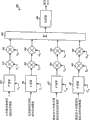
In another exemplary embodiments, base station 110 use disturb to be eliminated and to be reduced ul transmissions.In this exemplary embodiments, the input sample that process from receiver 354 base station 110, with reduction, carry out the ul transmissions of self terminal, the interference that estimation causes due to this terminal, and deduct described interference to obtain the input sample of next terminal from input sample.Base station 110 can be by same way reduction the ul transmissions from each residual terminal.By removing interference from the terminal that success is decoded, can realize compared with high s/n ratio for the terminal of reduction subsequently.
Fig. 7 shows the block diagram of receiving processor 360c, wherein receiving processor 360c carry out to disturb eliminate and or Fig. 3 in another exemplary embodiments of receiving processor 360.Receiving processor 360c comprises Solution Expander 512 and 522, modulation removes unit 514 and 534, channel estimation filters 516 and 536, combiner 538, demodulator/decoder 524, CRC verifier 526 and encoder/modulator 528, it is as above operated for as described in Fig. 6, but has following difference.First, Solution Expander 512 and 522 is inputted sample for terminal u receives.Whether be first terminal of being reduced, these input samples can be or can not be the input samples from receiver 354 if depending upon terminal u.The second, channel estimation filters 516 (but not combiner 538) is provided for the channel estimation value CHPu based on pilot tone of terminal u to demodulator/decoder 524.The 3rd, channel estimation filters 536 provides the CHDu of the channel estimation value based on data for terminal u.
Terminal u is correctly decoded a bag if, and encoder/modulator 528 is processed the described Bao Bingwei terminal u through decoding the data symbol producing is again provided.Then, code division multiple access modulation device 540 is expanded and is confused the data symbol (and possible pilot tone and control character) producing again, and exports chip for terminal u produces.Channel simulator 542 receives described output chips and from combiner 538 receive channel estimated values, will export chip and described channel estimation value convolution from code division multiple access modulation device 540, and provides Interference Estimation value for terminal u.Channel simulator 542 is the effect of terminal u analog wireless channel.Interference deducts the Interference Estimation value that unit 544 deducts the input sample of self terminal u, and provides input sample for next terminal u+1.
In the exemplary embodiments shown in Fig. 7, using the channel estimation value CHDu based on data from filter 536 is terminal u derivation Interference Estimation value.The described channel estimation value based on data can also demodulation and the decoding for terminal u by the mode to similar shown in Fig. 6.For example, as long as be correctly decoded a bag, just from the data symbol that produces again of described bag, derive the channel estimation value based on data, and use it for the Interference Estimation of current bag and the demodulate/decode of next bag.
The processing of Fig. 7 show needle to a terminal in a level.Can in U level, sequentially process U terminal (terminal in every one-level).The first order is that first terminal is processed the input sample from receiver 354, and provides input sample for the second level.Each following stages level be a terminal processes from the input sample of previous stage, and provide input sample for next stage.
Also can eliminate to process described terminal by parallel interference.In this situation, can in first leg, process all terminals.Can from input sample, estimate and the successfully interference of all terminals of decoding in first leg that deducts to control oneself.Then, can use the input sample of having eliminated interference again to process the terminal that success is not decoded in first leg.Described processing procedure can last till all successfully decodings of all terminals, or is eliminated from the interference of all terminals that success is decoded.Also can implement the combination of sequentially disturbing elimination and parallel interference to eliminate.In this situation, can the signal to noise ratio based on each terminal be arranged to a plurality of groups.Can sequentially process described group, and each terminal in can each group of parallel processing.
By use, disturb elimination, the signal to noise ratio of each terminal depends upon the level/order of the described terminal of reduction.The signal to noise ratio of first terminal can be the poorest, because also do not remove any interference.The signal to noise ratio of next terminal can be preferably, because be removed from the interference of first terminal.The signal to noise ratio of last terminal can be best, because removed the interference from all Leading Ends.In general, terminal also original place is more late, and signal to noise ratio is improved more step by step.
A large amount of variations in signal to noise ratio can be presented on for deriving the symbol of channel estimation value.Signal to noise ratio marked change can come to disturb and eliminate and/or for example come from, by dissimilar symbol (frequency pilot sign and data symbol) for channel estimating.Channel estimation value filters can mate the variation in signal to noise ratio, to obtain the channel estimation value of better quality.
The channel estimation filters of each terminal can the noise based on described terminal recently be selected, and it may be according to recovering the level/order of terminal and the grade of using filter.For having the first terminal of poor signal to noise ratio, channel estimation filters 516 can be for low signal-to-noise ratio, and channel estimation filters 536 can be for low or medium signal to noise ratio.For each follow-up terminal, filter 516 and 536 can be for the signal to noise ratio raising step by step.In general, for signal to noise ratio that continuously filter 516 of connecting stage can be used for raising step by step.Filter 536 for continuous connecting stage also can be for the signal to noise ratio raising step by step.For arbitrary giving, define the level, filter 536 all can be used for the signal to noise ratio higher than filter 516.Specific filter for every one-level all can compatibly be selected from all operational channel estimation filters.
Channel estimation technique described herein can also be for the data of using mixed automatic retransfer request (H-ARQ) to send.Use mixed automatic retransfer request, transmitter sends one or more transmission for bag, until described bag has been correctly decoded by receiver or send the transmission of maximum number for described bag.Mixed automatic retransfer request improves the reliability of transfer of data, and supports the rate adaptation to bag when there is changes in channel conditions.For the bag that uses mixed automatic retransfer request to send, demodulator/decoder 524 can be stored all transmission of described bag, and store transmission and current transmission is combined, and demodulation and decode described through combination of transmitted to reduce described bag.Different channels estimation filter can be used for the difference transmission of set bag, and it may be associated from different signal to noise ratios.
Channel estimation technique described herein can be used for single-input single-output (SISO), single many outputs of input (SIMO), many single outputs of input (MISO) and multiple-input and multiple-output (MIMO) transmission.Single input refers to uses single transmitting antenna, and how input refers to, uses a plurality of transmitting antennas for transfer of data.Single output refers to use single receive antenna, and many output refers to that a plurality of reception antennas of use are for data receiver.
Fig. 8 shows for the transmitter 810 of MIMO transmission and the block diagram of receiver 850.For downlink transmission, transmitter 810 can be a part for base station 110, and receiver 850 can be a part for terminal 120.For ul transmissions, transmitter 810 can be a part for terminal 120, and receiver 850 can be a part for base station 110.Transmitter 110 is equipped with a plurality of transmitting antennas (T).Receiver 850 is equipped with a plurality of reception antennas (R).
At transmitter 810 places, TX data processor 820 handle packet also produce S data symbol stream, 1≤S≤min{T wherein, R}.Each bag can or be crossed over a plurality of stream in a stream and send.TX spatial processor 822 is multiplexed by frequency pilot sign and data symbol, and the symbol through multiplexed is carried out to spatial mappings, and T output stream of chips offered to T transmitter 824a to 824t.Each transmitter 824 is processed its output stream of chips, and produces through modulation signal.From transmitter 824a, to T of 824t, through modulation signal, via antenna 826a, to 826t, transmit respectively.
At receiver 850 places, R antenna 852a to 852r receive from transmitter 810 through modulation signal, and each antenna 852 all provides received signal to receiver 854 separately.Each receiver 854 is all processed its received signal and input sample is provided.In receiving processor 860, receive 862 pairs of described input samples of spatial processor and carry out multiple-input and multiple-output detection, and institute's detected symbol is provided.Receiving data processor 864 further processes (for example, release of an interleave and decoding) institute's detected symbol and provides through decoding bag.
Controller/ processor 830 and 870 controls transmitter respectively 810 and the operation at receiver 850 places.Memory 832 and 872 is respectively transmitter 810 and receiver 850 storage data and program codes.
Fig. 9 shows the block diagram of receiving processor 860a, and described receiving processor 860a is the exemplary embodiments of the receiving processor 860 in Fig. 8.Receiving processor 860a is used successive interference cancellation (SIC) reduction from the transmission of transmitter 810.
For first order 910a, channel estimator 912a (for example) derives channel estimation value CH1 based on frequency pilot sign.Multiple-input and multiple-output detector 914a detects carrying out multiple-input and multiple-output from receiver 854a to R of 854r input sample flow, and provides symbol D1 after testing for first data flow of just reducing.Multiple-input and multiple-output detector 914a can implement ZF (ZF), least mean-square error (MMSE) or a certain other multiple-input and multiple-output detection schemes.Demodulator/decoder 916a wraps institute's detected symbol demodulation, release of an interleave and decoding to obtain through decoding, and further determines that described bag is correctly decoded or exists mistake.
If be correctly decoded described bag, encoder/modulator 918a encodes, interlocks and modulate described bag to produce described data symbol again.Channel estimator 924a derives the channel estimation value CHD1 based on data based on the described data symbol producing again and the detected symbol D1 of institute.Combiner 926a optionally combines from the channel estimation value CH1 of channel estimator 912a with from the channel estimation value CHD1 based on data of channel estimator 924a, and channel estimation value CH2 is provided.Data symbol and the channel estimation value CH2 of interference estimator 920a based on producing again estimates the interference causing through decoding bag due to described.Interference deducts unit 922a and deduct Interference Estimation value from described input sample, and provides input sample for next stage.
Each following stages can be used from the channel estimation value of previous stage and in the mode similar to the first order, the input sample of described level be carried out and processed.Every one-level is next stage input sample and channel estimation value is provided.
Signal to noise ratio is generally improved with following stages.Different channel estimation filters can be used for the channel estimator 912 and/or 924 in not at the same level, and can the noise based on these grades recently select.In general, the signal to noise ratio that can be used for raising step by step for the filter 924 of the following stages that continues.The specific filter that is ready to use in every one-level can be selected suitably from all channel estimation filters that can be used to use.
Figure 10 shows for carry out the exemplary embodiments of the process 1000 of recovering signal by optional channel estimation filters.For the signal that will reduce, determine filter and select to measure (block 1012).Can based on be with frequency pilot sign or data symbol derive channel estimation value, described signal business-pilot tone ratio, from a plurality of signals that will reduce, reduce the order of described signal, the signal to noise ratio of described signal and/or other information determine that described filter selection measures.Based on described filter, select to measure selective channel estimation filter (block 1014).A plurality of channel estimation filters with different length and/or frequency response can (for example) supply for different signal to noise ratio scopes.Applicable channel estimation filters can (for example) recently be selected based on selected to measure noise clear and definite or implicit indication by filter.Use selected channel estimation filters to derive channel estimation value (block 1016).Then, use described channel estimation value to reduce described signal (block 1018).
Figure 11 shows for carry out the exemplary embodiments of the process 1100 of recovering signal by different channels estimated value.Based on frequency pilot sign, also by the first channel estimation filters, derive the first channel estimation value (block 1112).Use described the first channel estimation value reduce first bag (block 1114).Produce again the data symbol (block 1116) of described first bag.Based on described data symbol, also with second channel estimation filter, derive second channel estimated value (block 1118).Based on described first and second channel estimation value, obtain the 3rd channel estimation value (block 1120).For example, if the quality of described second channel estimated value surpasses quality one scheduled volume (it can be determined by business-pilot tone ratio) of described the first channel estimation value, described second channel estimated value can be provided as to the 3rd channel estimation value.Also can the in the situation that of weighting or not weighting, combine described first and second channel estimation value, and be provided as the 3rd channel estimation value.In arbitrary situation, use described the 3rd channel estimation value reduction second bag (block 1122).
Figure 12 shows for reducing the exemplary embodiments of process 1200 of a plurality of signals.The first channel estimation filters that use has the first filter response derives the first channel estimation value (block 1212).With described the first channel estimation value, reduce first signal (block 1214).Estimate (block 1216) and remove the interference that (block 1218) causes due to described first signal.The channel estimation filters that use has the second filter response that is different from the first filter response derives second channel estimated value (block 1220).By described second channel estimated value, reduce secondary signal (block 1222).
For block 1216, can produce again described first signal.Can and use the 3rd channel estimation filters with the 3rd filter response that is different from the first filter response to derive the 3rd channel estimation value based on the described first signal producing again.Can (for example) based on the described first and the 3rd channel estimation value, obtain the 4th channel estimation value by following method: (1) is if business-pilot tone compares in particular range, combine the described first and the 3rd channel estimation value, or (2) otherwise, the described first or the 3rd channel estimation value is provided as to described the 4th channel estimation value.Because the interference that described first signal causes can be used described the 4th channel estimation value to derive.
Other signals can use the mode similar to described secondary signal to reduce.Described signal can be from different transmitters, for example different terminals.Described signal can also be corresponding to the different data streams in MIMO transmission.
Person of ordinary skill in the field should be appreciated that, can represent information and signal by any one of various different technologies and skill and technique.For example, with reference to data, instruction, order, information, signal, position, symbol and the chip that may mention in whole above-mentioned explanation, can be represented by voltage, electric current, electromagnetic wave, magnetic field or particle, light field or particle or its arbitrary combination.
Person of ordinary skill in the field should be further appreciated that various illustrative logical blocks, module, circuit and the algorithm steps in conjunction with exemplary embodiments disclosed herein, described can be embodied as electronic hardware, computer software or the combination of the two.For clearly illustrating the interchangeability of hardware and software, based on its functionality, summarize various exemplary components, piece, module, circuit and step above.This functional design constraints that hardware or software depend on application-specific and puts on whole system that is embodied as.Person of ordinary skill in the field all can implement for each application-specific described functional by different way, but this type of implementation decision should be interpreted as cause deviating from scope of the present invention.
Various illustrative logical blocks, module and the circuit in conjunction with embodiment disclosed herein, described all can be implemented or be carried out by lower array apparatus: general processor, digital signal processor (DSP), application-specific integrated circuit (ASIC) (ASIC), field programmable gate array (FPGA) or other programmable logic device, discrete gate or transistor logic, discrete hardware components or its are designed for any combination of function shown in enforcement above.General processor can be microprocessor, but another selection is that described processor can be any traditional processor, controller, microprocessor or state machine.Processor can also be embodied as the combination of calculation element, for example, digital signal processor with the combination of microprocessor, the combination of multi-microprocessor, one or more microprocessor combine with digital signal processor cores get, or other this type of configuration arbitrarily.
The method of describing in conjunction with embodiment disclosed herein or the step of algorithm can be embodied directly in hardware, be implemented in the software module of being carried out by processor or be implemented in the combination of the two.Software module can reside in RAM memory, flash memory, ROM memory, eprom memory, eeprom memory, register, hard disk, can extraction dish, in CD-ROM or affiliated technology in known arbitrary other forms of medium.Exemplary storage medium keeps communicating by letter (being for example coupled to described processor) with described processor, so that described processor can be from described read information and to described medium writing information.Or described medium can be the part of processor.Described processor and medium can reside in application-specific integrated circuit (ASIC).Described application-specific integrated circuit (ASIC) can reside in user terminal.Another is chosen as, and described processor and medium can be used as discrete assembly and reside in user terminal.
To the explanation of disclosed exemplary embodiments, be intended to make person of ordinary skill in the field all can make or use the present invention above.The various modifications of these exemplary embodiments will be apparent to person of ordinary skill in the field, and the General Principle defining herein can also be applicable to other exemplary embodiments under the prerequisite that does not deviate from the spirit or scope of the present invention.Therefore, the present invention does not intend to be restricted to exemplary embodiments shown in this article, but will give its broad range consistent with principle disclosed herein and novel feature.
Claims (20)
1. for a method for recovering signal, it comprises:
The first channel estimation filters that use has the first filter response generates the first channel estimation value;
Use described the first channel estimation value reduction first signal;
Reduce after described first signal first signal described in regeneration;
The second channel estimation filter that described first signal based on regeneration and use have the second filter response generates second channel estimated value, and described the second filter response is different from described the first filter response;
In response to detection business-pilot tone, than in specific scope, described first and second channel estimation value of combination is to obtain the 3rd channel estimation value; And
With described the 3rd channel estimation value, reduce secondary signal.
2. the method for claim 1, it further comprises in response to detection business-pilot tone than not in specific scope, provide described first or second channel estimated value as the 3rd channel estimation value.
3. the method for claim 1, it further comprises the quality of determining described the first channel estimation value.
4. method as claimed in claim 3, it further comprises the quality of determining described second channel estimated value.
5. the method for claim 1, it further comprises:
The interference that estimation causes due to described first signal;
Remove the described interference causing due to described first signal.
6. method as claimed in claim 5, wherein estimates based on described the 3rd channel estimation value the interference causing due to described first signal.
7. the method for claim 1, it further comprises:
The 3rd channel estimation filters that use has the 3rd filter response generates the 4th channel estimation value, and described the 3rd filter response is different from described the first filter response;
Use described the 4th channel estimation value reduction secondary signal;
The interference that estimation causes due to described secondary signal;
Remove the described interference causing due to described secondary signal.
8. method as claimed in claim 7, wherein said first signal is received from the first mobile terminal, and described secondary signal is received from the second mobile terminal.
9. method as claimed in claim 7, wherein said first and second signal transmits corresponding to multiple-input and multiple-output (MIMO).
10. the method for claim 1, it is further included in place, base station and receives described first signal.
11. 1 kinds of equipment for recovering signal, it comprises:
The first generating apparatus, the first channel estimation filters that its use has the first filter response generates the first channel estimation value;
The first reduction apparatus, it uses described the first channel estimation value reduction first signal;
Regeneration device, it reduces after described first signal first signal described in regeneration;
The second generating apparatus, the second channel estimation filter that its described first signal based on regeneration and use have the second filter response generates second channel estimated value, and described the second filter response is different from described the first filter response;
Combination unit, it is in response to detection business-pilot tone than in specific scope, and described first and second channel estimation value of combination is to obtain the 3rd channel estimation value; And
For reduce the device of secondary signal with described the 3rd channel estimation value.
12. equipment as claimed in claim 11, it further comprises generator, its in response to detection business-pilot tone than not in specific scope, provide described first or second channel estimated value as the 3rd channel estimation value.
13. equipment as claimed in claim 11, it further comprises the first determining device, it determines the quality of described the first channel estimation value.
14. equipment as claimed in claim 13, it further comprises the second determining device, it determines the quality of described second channel estimated value.
15. equipment as claimed in claim 11, it further comprises:
The first estimation unit, it estimates the interference causing due to described first signal;
The first apparatus for removing, it removes the described interference causing due to described first signal.
16. equipment as claimed in claim 15, wherein said the first estimation unit estimates based on described the 3rd channel estimation value the interference causing due to described first signal.
17. equipment as claimed in claim 11, it further comprises:
The 3rd generating apparatus, the 3rd channel estimation filters that its use has the 3rd filter response generates the 4th channel estimation value, and described the 3rd filter response is different from described the first filter response;
The second reduction apparatus, it uses described the 4th channel estimation value reduction secondary signal;
The second estimation unit, it estimates the interference causing due to described secondary signal;
The second apparatus for removing, it removes the described interference causing due to described secondary signal.
18. equipment as claimed in claim 17, wherein said first and second signal transmits corresponding to multiple-input and multiple-output (MIMO).
19. equipment as claimed in claim 17, wherein said first signal is received from the first mobile terminal, and described secondary signal is received from the second mobile terminal.
20. equipment as claimed in claim 11, wherein receive described first and second signal at place, base station.
Applications Claiming Priority (4)
| Application Number | Priority Date | Filing Date | Title |
|---|---|---|---|
| US70767305P | 2005-08-12 | 2005-08-12 | |
| US60/707,673 | 2005-08-12 | ||
| US11/492,605 US8165186B2 (en) | 2005-08-12 | 2006-07-24 | Channel estimation for wireless communication |
| US11/492,605 | 2006-07-24 |
Related Parent Applications (1)
| Application Number | Title | Priority Date | Filing Date |
|---|---|---|---|
| CN200680037396.0A Division CN101283559B (en) | 2005-08-12 | 2006-08-10 | Device and method for deriving channel estimation from wireless communication system |
Publications (2)
| Publication Number | Publication Date |
|---|---|
| CN101977168A CN101977168A (en) | 2011-02-16 |
| CN101977168B true CN101977168B (en) | 2014-04-09 |
Family
ID=37499233
Family Applications (3)
| Application Number | Title | Priority Date | Filing Date |
|---|---|---|---|
| CN200680037396.0A Active CN101283559B (en) | 2005-08-12 | 2006-08-10 | Device and method for deriving channel estimation from wireless communication system |
| CN2010105218512A Active CN101958730B (en) | 2005-08-12 | 2006-08-10 | Channel estimation for wireless communication |
| CN201010521845.7A Active CN101977168B (en) | 2005-08-12 | 2006-08-10 | Channel estimation for wireless communication |
Family Applications Before (2)
| Application Number | Title | Priority Date | Filing Date |
|---|---|---|---|
| CN200680037396.0A Active CN101283559B (en) | 2005-08-12 | 2006-08-10 | Device and method for deriving channel estimation from wireless communication system |
| CN2010105218512A Active CN101958730B (en) | 2005-08-12 | 2006-08-10 | Channel estimation for wireless communication |
Country Status (10)
| Country | Link |
|---|---|
| US (3) | US8165186B2 (en) |
| EP (3) | EP2273742B1 (en) |
| JP (3) | JP4897810B2 (en) |
| KR (3) | KR101185876B1 (en) |
| CN (3) | CN101283559B (en) |
| AT (1) | ATE532301T1 (en) |
| ES (1) | ES2373567T3 (en) |
| MY (1) | MY146679A (en) |
| TW (2) | TW201036363A (en) |
| WO (1) | WO2007021952A2 (en) |
Families Citing this family (48)
| Publication number | Priority date | Publication date | Assignee | Title |
|---|---|---|---|---|
| US7471932B2 (en) * | 2003-08-11 | 2008-12-30 | Nortel Networks Limited | System and method for embedding OFDM in CDMA systems |
| US8165186B2 (en) * | 2005-08-12 | 2012-04-24 | Qualcomm Incorporated | Channel estimation for wireless communication |
| US7864885B2 (en) * | 2006-11-15 | 2011-01-04 | Samsung Electronics Co., Ltd. | Multiple input multiple output (MIMO) transceiver with pooled adaptive digital filtering |
| US8102795B2 (en) * | 2007-03-09 | 2012-01-24 | Qualcomm Incorporated | Channel equalization with non-common midamble allocation in 3GPP TD-CDMA systems |
| US8014424B2 (en) * | 2007-06-25 | 2011-09-06 | Qualcomm Incorporated | Method and apparatus for using an unique index set for PSC sequence in a wireless communication system |
| JP5387575B2 (en) * | 2007-08-31 | 2014-01-15 | 富士通株式会社 | Wireless communication system and wireless communication method |
| KR101457690B1 (en) * | 2008-03-05 | 2014-11-04 | 삼성전자주식회사 | Apparatus and method for remoiving interference signal in a communication system |
| KR101402906B1 (en) * | 2008-06-23 | 2014-06-02 | 삼성전자주식회사 | Apparatus and method for power control in mobile communication system |
| US8428538B2 (en) * | 2008-07-09 | 2013-04-23 | Intel Mobile Communications GmbH | Channel estimator |
| US8238482B2 (en) | 2008-10-14 | 2012-08-07 | Apple Inc. | Techniques for improving channel estimation and tracking in a wireless communication system |
| KR101556636B1 (en) * | 2008-12-16 | 2015-10-01 | 삼성전자주식회사 | Method and apparatus for estimating channel using data channel |
| US8830918B2 (en) | 2009-03-16 | 2014-09-09 | Interdigital Patent Holdings, Inc. | Method and apparatus for performing uplink transmit diversity |
| US8615030B2 (en) * | 2009-05-04 | 2013-12-24 | Qualcomm Incorporated | Method and system for multi-user detection using two-stage processing |
| US8451963B2 (en) * | 2009-06-09 | 2013-05-28 | Qualcomm Incorporated | Method and system for interference cancellation |
| JP5712212B2 (en) * | 2009-07-15 | 2015-05-07 | ノーテル・ネットワークス・リミテッド | Method for selecting channel estimation method and radio receiver |
| US9256560B2 (en) * | 2009-07-29 | 2016-02-09 | Solarflare Communications, Inc. | Controller integration |
| US8509287B2 (en) * | 2009-10-23 | 2013-08-13 | Broadcom Corporation | Method and system for diversity processing utilizing a programmable interface suppression module |
| US8335286B2 (en) * | 2009-08-26 | 2012-12-18 | Qualcomm Incorporated | Methods for determining decoding order in a MIMO system with successive interference cancellation |
| KR101329335B1 (en) * | 2009-12-15 | 2013-11-20 | 한국전자통신연구원 | Apparatus and method for estimating of channel in frequency domain |
| US8594238B2 (en) | 2009-12-15 | 2013-11-26 | Electronics And Telecommunications Research Institute | Apparatus and method for estimating channel in channel domain |
| US8699553B2 (en) | 2010-02-19 | 2014-04-15 | Telefonaktiebolaget Lm Ericsson (Publ) | Data-aided SIR estimation |
| US8396168B2 (en) * | 2010-04-15 | 2013-03-12 | Telefonaktiebolaget L M Ericsson (Publ) | Channel estimation for equalizer using serial localization with indecision |
| US8699592B1 (en) * | 2010-06-11 | 2014-04-15 | Marvell International Ltd. | Systems and methods for estimating decoder noise power in OFDM systems |
| US8730989B2 (en) | 2011-02-11 | 2014-05-20 | Interdigital Patent Holdings, Inc. | Method and apparatus for closed loop transmit diversity transmission initial access |
| US9313744B2 (en) * | 2011-10-28 | 2016-04-12 | Qualcomm Incorporated | Method and apparatus for configuring traffic-to-pilot power ratios in heterogeneous networks |
| WO2013070651A1 (en) * | 2011-11-10 | 2013-05-16 | Marvell World Trade Ltd. | Channel estimation with decision feedback |
| WO2014018467A1 (en) * | 2012-07-23 | 2014-01-30 | Apple Inc. | Methods and systems for anchored down-selection in a coordinated multipoint transmission cluster |
| US8737457B2 (en) * | 2012-09-28 | 2014-05-27 | Telefonaktiebolaget L M Ericsson (Publ) | Adaptive smoothing of channel estimates |
| US9485061B2 (en) * | 2012-10-12 | 2016-11-01 | Samsung Electronics Co., Ltd. | Communication system with flexible repeat-response mechanism and method of operation thereof |
| US9350587B1 (en) | 2012-11-30 | 2016-05-24 | Marvell International Ltd. | System and method for timing error estimation |
| US9329929B2 (en) | 2013-03-20 | 2016-05-03 | Zte (Usa) Inc. | Soft maximum likelihood sequence estimation in digital communication |
| US9762351B2 (en) | 2013-03-20 | 2017-09-12 | Zte (Usa) Inc. | Statistics adaptive soft decision forward error correction in digital communication |
| US9553706B2 (en) * | 2013-05-15 | 2017-01-24 | Qualcomm Incorporated | Channel estimate under non-uniform reference signal pattern |
| US20150049731A1 (en) * | 2013-08-16 | 2015-02-19 | Mitsubishi Electric Research Laboratories, Inc. | Method for Coding OFDMA Data without Pilot Symbols |
| US10103904B2 (en) | 2013-10-04 | 2018-10-16 | Samsung Electronics Co., Ltd | Method and device for estimating channel in wireless communication system |
| US9350590B2 (en) * | 2013-10-25 | 2016-05-24 | Texas Instruments Incorporated | Method, system and apparatus for carrier frequency offset correction and channel estimation |
| EP2975787B1 (en) * | 2014-07-16 | 2018-10-03 | ZTE Corporation | Adaptive post digital filter and inter-symbol interference equalizer for optical communication |
| US9819419B2 (en) | 2014-10-07 | 2017-11-14 | Zte Corporation | Maximum likelihood sequence estimation of Quadrature Amplitude Modulated signals |
| WO2017019002A1 (en) * | 2015-07-24 | 2017-02-02 | Halliburton Energy Services, Inc. | Channel estimation in mud pulse telemetry |
| JP6538589B2 (en) * | 2016-02-26 | 2019-07-03 | 日本電信電話株式会社 | Wireless communication apparatus and interference reduction method |
| KR101943984B1 (en) | 2017-02-13 | 2019-01-31 | 전남대학교산학협력단 | Method for channel interpolation based on the lte sidelink system and apparatus for thereof |
| KR101943985B1 (en) | 2017-02-14 | 2019-01-31 | 전남대학교산학협력단 | Method for channel estimation based of lte and apparatus for thereof |
| KR101977623B1 (en) | 2017-06-30 | 2019-05-14 | 전남대학교산학협력단 | Interpolation and prediction method for fast link adaptation, and apparatus thereof |
| KR101940749B1 (en) | 2017-08-21 | 2019-01-22 | 전남대학교산학협력단 | Method for channel estimation and apparatus for thereof |
| KR101943983B1 (en) | 2017-08-22 | 2019-01-31 | 전남대학교산학협력단 | Method and apparatus for estimating channel in v2v communication |
| WO2021051362A1 (en) * | 2019-09-19 | 2021-03-25 | Nokia Shanghai Bell Co., Ltd. | Machine learning-based channel estimation |
| WO2023287415A1 (en) * | 2021-07-14 | 2023-01-19 | Zeku, Inc. | Apparatus and method for low power channel estimation |
| CN113436648B (en) * | 2021-08-26 | 2021-11-30 | 深圳市志泽科技有限公司 | Bidirectional communication system with transmission channel selection function |
Citations (4)
| Publication number | Priority date | Publication date | Assignee | Title |
|---|---|---|---|---|
| US6381290B1 (en) * | 1998-05-15 | 2002-04-30 | Ericsson Inc. | Mobile unit for pilot symbol assisted wireless system and method of improving performance thereof |
| EP1211819A1 (en) * | 2000-07-26 | 2002-06-05 | Matsushita Electric Industrial Co., Ltd. | Radio receiving device and radio receiving method |
| CN1551525A (en) * | 2003-03-06 | 2004-12-01 | ��Ѹ�Ƽ���˾ | A method for improving capacity of a reverse link channel in a wireless network |
| CN1555638A (en) * | 2001-08-07 | 2004-12-15 | �����ɷ� | Adaptive selection of the pilot filter for a wireless communication system |
Family Cites Families (28)
| Publication number | Priority date | Publication date | Assignee | Title |
|---|---|---|---|---|
| US4740236A (en) * | 1982-12-03 | 1988-04-26 | Ciba-Geigy Corporation | N-sulfonyl-imino-thiocarbonic acid diesters as herbicide antagonists for the protection of rice crops |
| US5572552A (en) | 1994-01-27 | 1996-11-05 | Ericsson Ge Mobile Communications Inc. | Method and system for demodulation of downlink CDMA signals |
| JP2746261B2 (en) | 1996-06-10 | 1998-05-06 | 日本電気株式会社 | DS-CDMA interference cancellation device |
| US5872816A (en) * | 1996-08-20 | 1999-02-16 | Hughes Electronics Corporation | Coherent blind demodulation |
| JP3335900B2 (en) | 1998-02-27 | 2002-10-21 | 松下電器産業株式会社 | Interference removal apparatus and interference removal method |
| JP2970656B1 (en) | 1998-06-25 | 1999-11-02 | 日本電気株式会社 | DS-CDMA multi-user interference canceller |
| JP3369489B2 (en) * | 1998-11-11 | 2003-01-20 | 松下電器産業株式会社 | Wireless communication device and wireless communication method |
| US6442154B1 (en) | 1999-04-15 | 2002-08-27 | Ericsson Inc. | Method and apparatus for successive cancellation using multiple signal timings |
| US6414988B1 (en) * | 1999-05-12 | 2002-07-02 | Qualcomm Incorporated | Amplitude and phase estimation method in a wireless communication system |
| JP3373457B2 (en) | 1999-08-24 | 2003-02-04 | 松下電器産業株式会社 | Wireless receiving apparatus and wireless receiving method |
| MY133723A (en) | 1999-09-17 | 2007-11-30 | Ericsson Telefon Ab L M | "apparatus and method for substantially eliminating a near-channel interfering amplitude modulated signal" |
| WO2001039032A1 (en) | 1999-11-11 | 2001-05-31 | Voyan Technology | Method for design and implementation of fixed-point filters for control and signal processing |
| EP1122891A1 (en) | 2000-01-31 | 2001-08-08 | Telefonaktiebolaget Lm Ericsson | Radio receiver and method therein |
| US6963546B2 (en) * | 2000-03-15 | 2005-11-08 | Interdigital Technology Corp. | Multi-user detection using an adaptive combination of joint detection and successive interface cancellation |
| JP2001326586A (en) | 2000-05-17 | 2001-11-22 | Nec Corp | Cdma communication system and channel estimate method used for it |
| JP2002043980A (en) * | 2000-07-24 | 2002-02-08 | Matsushita Electric Ind Co Ltd | Wireless receiving device and wireless receiving method |
| JP2002044172A (en) | 2000-07-26 | 2002-02-08 | Sanyo Electric Co Ltd | Phase correction circuit and mobile radio terminal provided with the phase correction circuit |
| JP2002232397A (en) * | 2001-01-31 | 2002-08-16 | Ntt Docomo Inc | Receiving processing method and receiving equipment in mobile communication system |
| US7133435B2 (en) * | 2001-06-20 | 2006-11-07 | Texas Instruments Incorporated | Interference cancellation system and method |
| US7058144B2 (en) | 2001-08-07 | 2006-06-06 | Conexant, Inc. | Intelligent control system and method for compensation application in a wireless communications system |
| US7035659B1 (en) * | 2001-10-22 | 2006-04-25 | Via Telecom Co., Ltd. | Estimation of forward link signal-to-noise ratio |
| DE10228103A1 (en) | 2002-06-24 | 2004-01-15 | Bayer Cropscience Ag | Fungicidal active ingredient combinations |
| GB2403113B (en) | 2002-08-16 | 2005-05-11 | Toshiba Res Europ Ltd | Channel estimation and training sequence determination |
| EP1401164A1 (en) | 2002-09-19 | 2004-03-24 | Telefonaktiebolaget Lm Ericsson | Bandwith estimation and adaptive filtering |
| JP2004120643A (en) * | 2002-09-27 | 2004-04-15 | Toshiba Corp | Rake receiver and receiving control program of the same |
| CN1757176B (en) | 2003-03-10 | 2010-09-08 | 三星电子株式会社 | Apparatus and method for estimating a velocity of a mobile station in a mobile communication system |
| US7433433B2 (en) | 2003-11-13 | 2008-10-07 | Telefonaktiebolaget L M Ericsson (Publ) | Channel estimation by adaptive interpolation |
| US8165186B2 (en) * | 2005-08-12 | 2012-04-24 | Qualcomm Incorporated | Channel estimation for wireless communication |
-
2006
- 2006-07-24 US US11/492,605 patent/US8165186B2/en active Active
- 2006-08-09 MY MYPI20063848A patent/MY146679A/en unknown
- 2006-08-10 EP EP10014083.9A patent/EP2273742B1/en active Active
- 2006-08-10 CN CN200680037396.0A patent/CN101283559B/en active Active
- 2006-08-10 CN CN2010105218512A patent/CN101958730B/en active Active
- 2006-08-10 KR KR1020097027227A patent/KR101185876B1/en active IP Right Grant
- 2006-08-10 EP EP06801274A patent/EP1913745B1/en active Active
- 2006-08-10 EP EP10004137.5A patent/EP2226949B1/en active Active
- 2006-08-10 KR KR1020087006053A patent/KR101143242B1/en active IP Right Grant
- 2006-08-10 JP JP2008526238A patent/JP4897810B2/en active Active
- 2006-08-10 ES ES06801274T patent/ES2373567T3/en active Active
- 2006-08-10 AT AT06801274T patent/ATE532301T1/en active
- 2006-08-10 WO PCT/US2006/031405 patent/WO2007021952A2/en active Application Filing
- 2006-08-10 CN CN201010521845.7A patent/CN101977168B/en active Active
- 2006-08-10 KR KR1020107021322A patent/KR101096889B1/en active IP Right Grant
- 2006-08-11 TW TW099116720A patent/TW201036363A/en unknown
- 2006-08-11 TW TW095129608A patent/TWI340568B/en not_active IP Right Cessation
-
2010
- 2010-03-04 US US12/717,598 patent/US8625656B2/en active Active
- 2010-10-12 US US12/902,992 patent/US8437380B2/en active Active
-
2011
- 2011-10-26 JP JP2011234958A patent/JP5442696B2/en active Active
- 2011-10-26 JP JP2011234959A patent/JP5442697B2/en active Active
Patent Citations (4)
| Publication number | Priority date | Publication date | Assignee | Title |
|---|---|---|---|---|
| US6381290B1 (en) * | 1998-05-15 | 2002-04-30 | Ericsson Inc. | Mobile unit for pilot symbol assisted wireless system and method of improving performance thereof |
| EP1211819A1 (en) * | 2000-07-26 | 2002-06-05 | Matsushita Electric Industrial Co., Ltd. | Radio receiving device and radio receiving method |
| CN1555638A (en) * | 2001-08-07 | 2004-12-15 | �����ɷ� | Adaptive selection of the pilot filter for a wireless communication system |
| CN1551525A (en) * | 2003-03-06 | 2004-12-01 | ��Ѹ�Ƽ���˾ | A method for improving capacity of a reverse link channel in a wireless network |
Also Published As
Similar Documents
| Publication | Publication Date | Title |
|---|---|---|
| CN101977168B (en) | Channel estimation for wireless communication | |
| KR101631428B1 (en) | Receiver and method for processing radio signals using soft pilot symbols | |
| CN101278489A (en) | A method and apparatus for received communication signal processing | |
| CN1965496A (en) | Wireless communication unit and method of processing a code division multiple access signal | |
| EP2504930B1 (en) | Blind spreading factor detection for wcdma | |
| US6765952B2 (en) | Transmit diversity pilot processing | |
| US20060098600A1 (en) | Decreasing computational complexity of TD-SCDMA measurement process | |
| EP1372308B1 (en) | Method and apparatus for decision directed channel equalization in spread spectrum receivers | |
| Huayu et al. | Iterative joint detection and decoding based on intereference cancellation |
Legal Events
| Date | Code | Title | Description |
|---|---|---|---|
| C06 | Publication | ||
| PB01 | Publication | ||
| C10 | Entry into substantive examination | ||
| SE01 | Entry into force of request for substantive examination | ||
| C14 | Grant of patent or utility model | ||
| GR01 | Patent grant |