US8622221B2 - Device for filtering polymer melts - Google Patents
Device for filtering polymer melts Download PDFInfo
- Publication number
- US8622221B2 US8622221B2 US12/762,454 US76245410A US8622221B2 US 8622221 B2 US8622221 B2 US 8622221B2 US 76245410 A US76245410 A US 76245410A US 8622221 B2 US8622221 B2 US 8622221B2
- Authority
- US
- United States
- Prior art keywords
- distribution element
- central distribution
- filtering device
- set forth
- receiving chamber
- Prior art date
- Legal status (The legal status is an assumption and is not a legal conclusion. Google has not performed a legal analysis and makes no representation as to the accuracy of the status listed.)
- Expired - Fee Related, expires
Links
- 238000001914 filtration Methods 0.000 title claims abstract description 41
- 239000000155 melt Substances 0.000 title claims abstract description 29
- 229920000642 polymer Polymers 0.000 title 1
- 238000009826 distribution Methods 0.000 claims abstract description 74
- 238000004519 manufacturing process Methods 0.000 claims abstract description 3
- 230000007704 transition Effects 0.000 claims description 2
- 238000007599 discharging Methods 0.000 claims 1
- 238000013022 venting Methods 0.000 description 18
- 238000004140 cleaning Methods 0.000 description 6
- 238000012423 maintenance Methods 0.000 description 5
- 238000013461 design Methods 0.000 description 4
- 239000000463 material Substances 0.000 description 4
- 230000008901 benefit Effects 0.000 description 2
- 230000001747 exhibiting effect Effects 0.000 description 2
- 238000012986 modification Methods 0.000 description 2
- 230000004048 modification Effects 0.000 description 2
- 230000009977 dual effect Effects 0.000 description 1
- 239000002184 metal Substances 0.000 description 1
- 238000000034 method Methods 0.000 description 1
- 238000003825 pressing Methods 0.000 description 1
- 230000008569 process Effects 0.000 description 1
- 230000009467 reduction Effects 0.000 description 1
- 230000000284 resting effect Effects 0.000 description 1
- 238000007789 sealing Methods 0.000 description 1
- 238000000926 separation method Methods 0.000 description 1
- 239000007787 solid Substances 0.000 description 1
- 239000011343 solid material Substances 0.000 description 1
- 238000012546 transfer Methods 0.000 description 1
- 238000009827 uniform distribution Methods 0.000 description 1
- 238000011144 upstream manufacturing Methods 0.000 description 1
Images


Classifications
-
- B—PERFORMING OPERATIONS; TRANSPORTING
- B29—WORKING OF PLASTICS; WORKING OF SUBSTANCES IN A PLASTIC STATE IN GENERAL
- B29C—SHAPING OR JOINING OF PLASTICS; SHAPING OF MATERIAL IN A PLASTIC STATE, NOT OTHERWISE PROVIDED FOR; AFTER-TREATMENT OF THE SHAPED PRODUCTS, e.g. REPAIRING
- B29C48/00—Extrusion moulding, i.e. expressing the moulding material through a die or nozzle which imparts the desired form; Apparatus therefor
- B29C48/25—Component parts, details or accessories; Auxiliary operations
- B29C48/36—Means for plasticising or homogenising the moulding material or forcing it through the nozzle or die
- B29C48/50—Details of extruders
- B29C48/69—Filters or screens for the moulding material
- B29C48/694—Cylindrical or conical filters
-
- B—PERFORMING OPERATIONS; TRANSPORTING
- B29—WORKING OF PLASTICS; WORKING OF SUBSTANCES IN A PLASTIC STATE IN GENERAL
- B29C—SHAPING OR JOINING OF PLASTICS; SHAPING OF MATERIAL IN A PLASTIC STATE, NOT OTHERWISE PROVIDED FOR; AFTER-TREATMENT OF THE SHAPED PRODUCTS, e.g. REPAIRING
- B29C48/00—Extrusion moulding, i.e. expressing the moulding material through a die or nozzle which imparts the desired form; Apparatus therefor
- B29C48/03—Extrusion moulding, i.e. expressing the moulding material through a die or nozzle which imparts the desired form; Apparatus therefor characterised by the shape of the extruded material at extrusion
Definitions
- the invention relates to a filtering device for plastic melts exhibiting at least one screen plunger arranged in a screen plunger hole movably between an inlet channel and an outlet channel of a housing and containing replaceable, three-dimensional filter elements, whereby the inside of the filter element is connected to at least one melt channel formed in the screen plunger, said melt channel being connected to the inlet or outlet channel of the housing when in the production position.
- Such a filtering device is known from DE 44 20 119 C1.
- housing and screen carrier plungers are specially matched to each other with regard to the inlet and outlet openings of the melt channels, such that it is not possible to place the also known screen carrier plungers into the housing when they exhibit screen surfaces with an onflow perpendicular to the longitudinal axis.
- filtering devices with such screen carrier plungers exhibiting screen surfaces with an onflow perpendicular to the longitudinal axis cannot be converted to operate using a screen carrier plunger with cartridge filters as known from the aforementioned patent document.
- the objective of the invention to improve a filtering device of the aforementioned kind such that easy maintenance and cleaning is possible, while still providing a large filtration surface.
- a filtering device in which the screen plunger has at least one receiving chamber that can be closed by a cover on the face side, and in which a plurality of filter elements are bundled together with a central distribution element to a filter cartridge that can be placed in the receiving chamber.
- the distinctive feature of the design according to the invention is to form a solid screen carrier plunger in part as a tube and to populate the receiving chamber created therein with a filter cartridge.
- the filter cartridge is formed from numerous candle filters, which are essentially known. These are positioned at the joint central distribution element, are fed from there, and discharge the melt across it.
- the preferred flow through the filter elements is from the outside to the inside. This avoids expanding of the filter elements due to a high differential pressure between the inner and outer side. However, with a proper design of the filter elements or with a reduction of the forces acting upon them, a reverse direction of the flow is possible as well.
- An additional advantage is that a perpendicular flow through the screen carrier plunger is possible.
- the filter plungers which in most existing filtering devices are located in the openings for the melt feed and discharge diametrically opposite the borehole, can be connected to a screen carrier plunger designed according to the invention, with the flow passing through them. Therefore, even already existing filtering devices can be provided with the screen carrier plungers designed according to the invention without the need to modify the housing and the screen plunger boreholes.
- filter elements are positioned on both face sides of the central distribution element. This creates a dual pack of filter elements with a disc-shaped central distribution element in the center.
- the central distribution element being located in the center doubles the usable filter surfaces once more.
- the receiving chamber in the screen carrier plunger is divided into two screen chambers that can be ventilated separate from each other after cleaning.
- the melt is guided via a first melt channel located on the inside of the central distribution element into a receiving chamber and from there flows from the outside through the outer jacket of the candle filter.
- the melt that flows from the inside of the respective filter element via several outlet openings is collected in a second melt channel in the central distribution element and from there discharges from the screen plunger.
- the flow through the filtering device can also occur in the other direction.
- the melt is distributed via the second melt channel to numerous outlet openings, which are followed by the inner sides of the candle filters or the other three-dimensional filter elements, respectively.
- the melt then exits through the outer cover of the filter elements and enters into the receiving chamber of the screen carrier plunger. From there, the melt flows via an additional outlet opening into the second melt channel in the central distribution element and from there to the outlet opening of the screen carrier plunger.
- the filter elements are formed by candle filters, which extend parallel to the longitudinal axis of the screen plunger, and with their open side are attached to openings on the face side of the central distribution element.
- a second melt channel extends in the central distribution element to at least one distribution tube that protrudes into the receiving chamber and exhibits several outlet openings, and where each said distribution tube is followed by at least one filter element.
- the distribution tube enables the flow of the melt also in the depth of the receiving chamber, facing away from the central distribution element, whereby a uniform distribution to the filter elements that are strung along the distribution tube occurs.
- Short, radially oriented candle filters or disc-shaped, hollow filters are used as filter elements and surround the distribution tube at least in the area of its, in particular radial outlet openings.
- the screen carrier plunger exhibits an outer, smooth cover area to enable closing of the channels that conduct the melt. This serves the purpose of taking one respective screen carrier plunger out of operation for maintenance, while the other screen carrier plunger continues with the filtration of the melt.
- the rear section can be formed by a solid material or a tube.
- the central distribution element is located approximately in the center of the receiving chamber and divides said chamber into two chambers that are sealed from each other. This allows for the simultaneous use of two filter cartridges, thus doubling the filter surface.
- a rod or a tube that leads from the central distribution element to the cover facilitates the removal of the filter cartridge from the receiving chamber.
- pressure is applied from the cover to the central distribution element via the rod or the tube pressing said central distribution element with its edge onto the seal seat.
- a tube can be provided there as well allowing free discharge of the melt at the end.
- FIG. 1 is a perspective view of a first embodiment of a filtering device according to the present invention.
- FIG. 2 is a perspective view of a screen carrier plunger according to the first embodiment.
- FIG. 3 is a perspective view of a filter cartridge for the screen carrier plunger.
- FIG. 4 is a sectional view of the screen carrier plunger.
- FIG. 5 is a perspective view of a second embodiment of a filtering device.
- FIG. 6 is a perspective view of a screen carrier plunger according to the second embodiment of the present invention.
- FIG. 7 is a perspective view of a filter cartridge for the screen carrier plunger according to the second embodiment.
- FIG. 8 is a perspective view of a third embodiment of a filtering device.
- FIG. 9 is a perspective view of a filter cartridge for the screen carrier plunger according to the third embodiment.
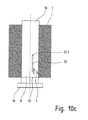
- FIG. 10 a to FIG. 10 c are partial sectional top view of a filtering device in the venting and operating positions.
- FIGS. 1-10 c of the drawings The preferred embodiments of the present invention will now be described with reference to FIGS. 1-10 c of the drawings. Identical elements in the various figures are designated with the same reference numerals.
- FIG. 1 shows a filtering device 100 that features a housing 1 with two screen carrier plunger boreholes 4 .
- the screen carrier plunger boreholes 4 are connected to inlet and outlet openings 3 , 2 via channels 5 , 6 .
- the screen carrier plunger 10 In its inner receiving chamber 14 , the screen carrier plunger 10 includes a filter cartridge 30 . Towards the outside, the receiving chamber 14 is closed through a cover 16 located at the face side. In the rear area, the screen carrier plunger 10 exhibits an outer, smooth jacket area to enable closing of the channels 5 , 6 that conduct the melt.
- FIG. 2 shows a semi-section of the screen carrier plunger 10 removed from the housing 1 such that the filter cartridge 30 contained in the receiving chamber 14 is visible.
- the replaceable filter cartridge 30 essentially consists of a central distribution element 20 and filter elements 25 placed therein.
- the inflow opening 12 can be recognized in the central distribution element 20 , which is connected to an outlet opening 23 via a first melt channel 22 such that a direct path is established for the flow of the melt through the central distribution element 20 and into the receiving chamber 14 .
- FIG. 3 shows the filter cartridge 30 removed from the screen carrier plunger 10 , said filter cartridge consisting in this shown first embodiment of the central, disc-shaped central distribution element 20 and several candle filters 25 screwed into them on the face side.
- the candle filters 25 extend on both sides of the central distribution element 20 .
- the central distribution element 20 also separates the receiving chamber 14 in the screen carrier plunger 10 into two separate chambers.
- a lay-on edge 29 of the central distribution element rests on a respective shoulder at the inner jacket of the receiving chamber 14 and in this manner enables the tight separation of the receiving chamber into one chamber located before and another one located after the central distribution element 20 .
- it defines the axial position of the filter cartridge 30 .
- a protrusion 28 engages in a compatible recess inside the receiving chamber 14 such that the filter cartridge 30 is secured and prevented from rotating, and that it is ensured that the openings 11 , 12 (cf. FIG. 4 ) are located in the screen carrier plunger 10 in line with mouths of the melt channels in the central distribution element 20 .
- Distribution tubes 27 that extend from the central distribution element 20 into the receiving chamber affect a uniform melt flow in the depth of the receiving chamber. Radial outlet openings 27 . 1 are provided for this purpose.
- the distribution tube 27 pointing in the direction of the cover 16 facilitates removing of the filter cartridge 30 from the receiving chamber 14 .
- pressure is applied from the cover 16 to the central distribution element 20 via the rod 27 , and said central distribution element 20 is pressed onto the seal seat with its edge 29 .
- the distribution tube 27 is arranged centrally within the candle filters 25 , which are grouped around said tube in a reference circle.
- the outlet opening 23 is arranged in the center of the central distribution element 20 followed by the distribution tube 27 .
- outlet opening 24 one of the locations designated as outlet opening 24 is left free for a candle filter 25 .
- FIG. 4 shows a section through the screen carrier plunger 10 and the central distribution element 20 .
- Melt that is fed through the channel 3 in the housing 1 enters a first melt channel 22 through a first outlet opening 12 in the screen carrier plunger 10 and from there into the receiving opening 14 via the openings 23 .
- the melt enters through the porous filter material of the candle filters 25 , which, for example, consists of a metal mesh, into the candle filters 25 , which are located upstream of the outlet openings 24 in the central distribution element 20 .
- the melt flows into the second melt channel 21 —exhibiting a clasp shape in a cross-sectional view—that acts as a collector and re-combines the partial melt streams from the various openings 24 .
- discharge occurs via a second outlet opening 11 out of the screen carrier plunger 10 into the channel 6 in the housing 1 and finally at the discharge opening 2 into a subsequent process.
- FIGS. 5 to 7 and 8 to 9 show additional embodiments of a filtering device 100 ′ or 100 ′′, respectively, which differ from the filtering device 100 described above only by the design of the inner filter cartridge.
- FIGS. 5 , 6 and 7 show a screen carrier plunger 210 with a filter cartridge 230 , which consists of a disc-shaped central distribution element 220 with a distribution tube 227 in the center and candle filters 225 placed radially onto said distribution tube.
- a flow path is formed in the central distribution element 220 between an inlet opening 212 and a melt channel 222 and ends at an outlet opening 223 .
- the melt enters through the chamber, which is separated from the receiving chamber 214 through the central distribution element 220 , and from there flows through the filter material of the candle filters 225 via the tube 227 back into the central distribution element 220 , from where it is discharged through an internal melt channel.
- the candle filters 225 are significantly smaller than the candle filters 25 of the first exemplary embodiment of a filter cartridge 30 according to FIGS. 1 to 4 , which extend in the longitudinal direction from the central distribution element 20 .
- the candle filters 225 are placed radially onto the central distribution tube 227 , acting as a melt collector or melt distributor depending on the direction of flow; said central distribution tube 227 also facilitates the removal of the filter cartridge 230 from the screen carrier plunger 10 after removal of the cover 227 .
- FIG. 6 shows the screen carrier plunger 210 with the inserted filter cartridge 230 .
- a large filtering surface is provided by arranging numerous radially extending candle filters 225 , even more so in several rows distributed around the circumference of the tube 227 . It is doubled by the fact that such an arrangement of candle filters 225 extends on both sides of the central distribution element 220 .
- the melt channel 222 extends in the form of an arch across a portion of the circumference of the central distribution element 220 and then transitions into several internal melt channels, each of them emptying into an outlet opening 23 .
- FIGS. 8 and 9 show a third embodiment of a filtering device 100 ′′.
- the housing 1 with the screen carrier plunger boreholes 4 is again not altered from the embodiments described above.
- FIG. 9 Different is a screen carrier plunger 310 or a filter cartridge 330 contained therein, a perspective view of which is pictured in FIG. 9 .
- the melt entering at an inlet opening 322 is split into several partial streams, which empty into the receiving chamber 314 at an outlet opening 323 .
- a uniform flow from all sides is achieved by arranging several outlet openings 323 around a central tube 327 with a filter element 325 .
- the tube 327 extends to a cover 316 .
- the filter element 325 consists of several ring-shaped filter discs 325 . 1 , 325 . 2 . . . . At least the filter discs 325 . 1 , . . . , 325 . 10 on the ends connect tightly to the tube 327 with an inner edge such that melt that flows through the receiving chamber 314 is forced to pass through the filter material before being discharged into the central distribution element 320 through the openings 327 . 1 in the tube 327 .
- FIGS. 10 a to 10 c are used to describe venting and pre-flooding of the chambers in the screen carrier plunger 10 after the end of cleaning.
- FIG. 10 a shows the operational position.
- the screen carrier plunger 10 is fully inside the housing.
- the cover 16 may be resting on the front of the housing, for example, in order to achieve a defined position.
- a venting hole 32 Placed in the front area of the screen carrier plunger 10 , i.e., facing the cover 16 , is a venting hole 32 that is connected to the front chamber of the receiving chamber 14 .
- a venting hole 32 In order to vent and pre-flood the front portion of the receiving chamber 14 in the screen carrier plunger 10 , it is moved into a first venting position according to FIG. 10 c , i.e., sufficiently moved out of the housing such that the venting hole 32 is positioned free in front of an edge 8 of the housing. Air and melt can escape to the outside via this hole.
- a venting grove 31 is provided that, starting from a venting hole 31 . 1 , extends in the axial direction on the outer jacket surface to near the venting hole 32 . Due to the closeness of the angled end of the venting groove 31 to the venting hole 32 , the screen carrier plunger only needs to be moved slightly axially from the position according to FIG. 10 a or the position according to FIG. 10 c in order to reach a second venting position according to FIG. 10 b , where the venting groove 31 reaches a mouth of a venting hole 7 placed in the housing 1 .
- a melt discharge from the receiving chamber 14 with a significantly reduced volume flow is possible via the venting hole 32 , or via the venting hole 31 . 1 , the venting groove 31 and the venting hole 7 , respectively.
- venting and pre-flooding is finished and the screen carrier plunger 10 can be returned to the operating position according to FIG. 10 a.
Landscapes
- Engineering & Computer Science (AREA)
- Mechanical Engineering (AREA)
- Extrusion Moulding Of Plastics Or The Like (AREA)
- Filtration Of Liquid (AREA)
Abstract
Description
Claims (15)
Applications Claiming Priority (6)
| Application Number | Priority Date | Filing Date | Title |
|---|---|---|---|
| DE1020090026487 | 2009-04-24 | ||
| DE102009002648 | 2009-04-24 | ||
| DE102009002648 | 2009-04-24 | ||
| DE102009032652A DE102009032652B4 (en) | 2009-04-24 | 2009-07-09 | Filter device for plastic melts |
| DE102009032652 | 2009-07-09 | ||
| DE1020090326529 | 2009-07-09 |
Publications (2)
| Publication Number | Publication Date |
|---|---|
| US20100270229A1 US20100270229A1 (en) | 2010-10-28 |
| US8622221B2 true US8622221B2 (en) | 2014-01-07 |
Family
ID=42342791
Family Applications (1)
| Application Number | Title | Priority Date | Filing Date |
|---|---|---|---|
| US12/762,454 Expired - Fee Related US8622221B2 (en) | 2009-04-24 | 2010-04-19 | Device for filtering polymer melts |
Country Status (4)
| Country | Link |
|---|---|
| US (1) | US8622221B2 (en) |
| EP (1) | EP2246174B1 (en) |
| JP (1) | JP2010253473A (en) |
| CN (1) | CN101870163A (en) |
Cited By (3)
| Publication number | Priority date | Publication date | Assignee | Title |
|---|---|---|---|---|
| US10814254B2 (en) | 2016-10-31 | 2020-10-27 | Westlake Longview Corporation | Candle filter support and plate assembly for polymer melts |
| US20210162324A1 (en) * | 2016-10-17 | 2021-06-03 | Next Generation Analytics Gmbh | Filter system for viscous or highly viscous liquids, in particular plastic melts and method for filtering viscous or highly viscous liquids |
| US20220355531A1 (en) * | 2018-05-07 | 2022-11-10 | PSI-Polymer Systems, Inc. | Filtration apparatuses and screen changer devices for polymer processing and related methods |
Families Citing this family (8)
| Publication number | Priority date | Publication date | Assignee | Title |
|---|---|---|---|---|
| JP6141768B2 (en) * | 2010-12-16 | 2017-06-07 | アミアド ウォーター システムズ リミテッドAmiad Water Systems Ltd. | Filtration system and components thereof |
| DE102012100641A1 (en) * | 2011-07-29 | 2013-01-31 | Kreyenborg Verwaltungen Und Beteiligungen Gmbh & Co. Kg | Filter apparatus for large surface filtration of e.g. polyamide, has filter insert pushed into opening by displacement of support element, and closure element inserted into housing bore or at opening of bore when lowering support element |
| JP6006653B2 (en) * | 2013-02-04 | 2016-10-12 | 出光興産株式会社 | Polycarbonate resin extrusion granulator and polycarbonate resin extrusion granulation method |
| CN103802297B (en) * | 2014-03-08 | 2018-07-27 | 湖南博盛工业有限公司 | Die head of plastic extruding machine |
| CN105563793B (en) * | 2016-02-27 | 2018-10-26 | 浙江乐能科技有限公司 | One kind is rotatably without fluctuation net-changing device |
| DE202016105013U1 (en) * | 2016-09-09 | 2016-09-23 | Nordson Corporation | Filter candle for separating impurities from a plastic melt |
| DE102021128194A1 (en) * | 2021-10-28 | 2023-05-04 | Maag Germany Gmbh | Method for operating a filter device and filter device |
| CN117225059B (en) * | 2023-11-16 | 2024-01-19 | 闻喜县唯源调味食品有限公司 | Suspended impurity and sediment comprehensive filtering system |
Citations (2)
| Publication number | Priority date | Publication date | Assignee | Title |
|---|---|---|---|---|
| DE4420119C1 (en) | 1994-05-03 | 1995-06-29 | Kreyenborg Verwaltungen | Continuous filter for thermoplastic polymer |
| US5578207A (en) * | 1994-05-03 | 1996-11-26 | Firma Kreyenborg Verwaltungen Und Beteiligungen Kg | Filter device for extruders having a screen plunger with longitudinally arranged candle filters |
Family Cites Families (5)
| Publication number | Priority date | Publication date | Assignee | Title |
|---|---|---|---|---|
| US5200077A (en) * | 1991-04-08 | 1993-04-06 | Memtec America Corporation | Backflushable rotary melt polymer filter apparatus |
| US5462653A (en) * | 1994-02-15 | 1995-10-31 | Hills, Inc. | Apparatus for continuous polymer filtration |
| DE19636067A1 (en) * | 1995-09-18 | 1997-03-20 | Barmag Barmer Maschf | Filtering of plastic melt and filtering equipment for reducing flow variation |
| JP3641095B2 (en) * | 1997-03-05 | 2005-04-20 | 株式会社神戸製鋼所 | Screen changer for resin molding machine |
| WO2002006028A2 (en) * | 2000-07-18 | 2002-01-24 | Hills, Inc. | Filtration system utilizing a single valve to direct fluid streams between filter assemblies and corresponding methods |
-
2010
- 2010-04-19 US US12/762,454 patent/US8622221B2/en not_active Expired - Fee Related
- 2010-04-22 EP EP10160806.5A patent/EP2246174B1/en not_active Not-in-force
- 2010-04-23 CN CN201010166174A patent/CN101870163A/en active Pending
- 2010-04-26 JP JP2010101135A patent/JP2010253473A/en active Pending
Patent Citations (2)
| Publication number | Priority date | Publication date | Assignee | Title |
|---|---|---|---|---|
| DE4420119C1 (en) | 1994-05-03 | 1995-06-29 | Kreyenborg Verwaltungen | Continuous filter for thermoplastic polymer |
| US5578207A (en) * | 1994-05-03 | 1996-11-26 | Firma Kreyenborg Verwaltungen Und Beteiligungen Kg | Filter device for extruders having a screen plunger with longitudinally arranged candle filters |
Cited By (6)
| Publication number | Priority date | Publication date | Assignee | Title |
|---|---|---|---|---|
| US20210162324A1 (en) * | 2016-10-17 | 2021-06-03 | Next Generation Analytics Gmbh | Filter system for viscous or highly viscous liquids, in particular plastic melts and method for filtering viscous or highly viscous liquids |
| US10814254B2 (en) | 2016-10-31 | 2020-10-27 | Westlake Longview Corporation | Candle filter support and plate assembly for polymer melts |
| US11691094B2 (en) | 2016-10-31 | 2023-07-04 | Westlake Longview Corporation | Candle filter support and plate assembly for polymer melts |
| US12239925B2 (en) | 2016-10-31 | 2025-03-04 | Westlake Longview Corporation | Candle filter support and plate assembly for polymer melts |
| US20220355531A1 (en) * | 2018-05-07 | 2022-11-10 | PSI-Polymer Systems, Inc. | Filtration apparatuses and screen changer devices for polymer processing and related methods |
| US12214536B2 (en) * | 2018-05-07 | 2025-02-04 | PSI-Polymer Systems, Inc. | Filtration apparatuses and screen changer devices for polymer processing and related methods |
Also Published As
| Publication number | Publication date |
|---|---|
| JP2010253473A (en) | 2010-11-11 |
| US20100270229A1 (en) | 2010-10-28 |
| EP2246174B1 (en) | 2013-06-05 |
| CN101870163A (en) | 2010-10-27 |
| EP2246174A1 (en) | 2010-11-03 |
Similar Documents
| Publication | Publication Date | Title |
|---|---|---|
| US8622221B2 (en) | Device for filtering polymer melts | |
| US4379051A (en) | Filtering apparatus | |
| US4891133A (en) | Chromatography apparatus | |
| US6443312B1 (en) | Self-cleaning filter | |
| CN105268230B (en) | Filter element and the method for filtering fluid | |
| US8313645B2 (en) | Filter device | |
| HU182167B (en) | Cleaning apparatus with back flushing device for dust filters | |
| KR102187611B1 (en) | Filtration unit with automatic backwash means | |
| EP1888200A1 (en) | Filter cartridge and method of construction thereof | |
| CN106948983A (en) | Combination type filter element | |
| JPS63185618A (en) | Device for separating solid of fine particle from pressed fluid | |
| HRP20151246T1 (en) | Capsule including actuation element, method and device for processing said capsule | |
| RU2009127388A (en) | DISK FILTER SECTOR AND DISK FILTER | |
| CN103402599A (en) | Filtering device | |
| JPH03208619A (en) | Screen bag replacement device equipped with cylindrical screen bag and operation of said device | |
| EP3434349B1 (en) | Fluid degassing systems | |
| JP2015517906A5 (en) | ||
| CN106455609A (en) | Method of and press for separating cocoa mass into cocoa butter and cocoa cake | |
| CN112870795A (en) | A new type of renewable filter element | |
| CN116982844B (en) | Material receiving mechanism, extraction device and coffee machine | |
| JP4255070B2 (en) | Water purification cartridge, method for producing the same, and water purifier provided with the same | |
| CN219308395U (en) | High-efficiency membrane separation device | |
| CN214913725U (en) | Device for trapping particles in fluid | |
| CN104906853B (en) | Multi-channel filter element | |
| CN109849299B (en) | Built-in split-flow filter block |
Legal Events
| Date | Code | Title | Description |
|---|---|---|---|
| AS | Assignment |
Owner name: KREYENBORG BETEILIGUNGEN UND VERWALTUNGEN GMBH & C Free format text: ASSIGNMENT OF ASSIGNORS INTEREST;ASSIGNORS:HARTMANN, FRANK;ANDRESS, MICHAEL;REEL/FRAME:024250/0828 Effective date: 20100412 |
|
| AS | Assignment |
Owner name: KREYENBORG GMBH, GERMANY Free format text: ASSIGNMENT OF ASSIGNORS INTEREST;ASSIGNOR:KREYENBORG VERWALTUNGEN UND BETEILIGUNGEN GMBH & CO. KG;REEL/FRAME:027783/0079 Effective date: 20120224 |
|
| FEPP | Fee payment procedure |
Free format text: PAYOR NUMBER ASSIGNED (ORIGINAL EVENT CODE: ASPN); ENTITY STATUS OF PATENT OWNER: LARGE ENTITY |
|
| AS | Assignment |
Owner name: NORDSON HOLDINGS S.A.R.L. & CO. KG, GERMANY Free format text: ASSIGNMENT OF ASSIGNORS INTEREST;ASSIGNOR:NORDSON PPS GMBH;REEL/FRAME:035181/0310 Effective date: 20150316 Owner name: NORDSON KREYENBORG GMBH, GERMANY Free format text: CHANGE OF NAME;ASSIGNOR:KREYENBORG GMBH;REEL/FRAME:035212/0226 Effective date: 20131018 Owner name: NORDON PPS GMBH, GERMANY Free format text: CHANGE OF NAME;ASSIGNOR:NORDSON KREYENBORG GMBH;REEL/FRAME:035212/0264 Effective date: 20140825 |
|
| AS | Assignment |
Owner name: NORDSON PPS GMBH, GERMANY Free format text: CORRECTIVE ASSIGNMENT TO CORRECT THE ASSIGNEE NAME PREVIOUSLY RECORDED AT REEL: 035212 FRAME: 0264. ASSIGNOR(S) HEREBY CONFIRMS THE CHANGE OF NAME;ASSIGNOR:NORDSON KREYENBORG GMBH;REEL/FRAME:035248/0709 Effective date: 20140825 |
|
| AS | Assignment |
Owner name: KREYENBORG VERWALTUNGEN UND BETEILIGUNGEN GMBH & C Free format text: CORRECTIVE ASSIGNMENT TO CORRECT THE NAME OF ASSIGNEE TO KREYENBORG VERWALTUNGEN UND BETEILIGUNGEN GMBH & CO. KG PREVIOUSLY RECORDED ON REEL 024250 FRAME 0828. ASSIGNOR(S) HEREBY CONFIRMS THE ASSIGNMENT TO KREYENBORG VERWALTUNGEN UND BETEILIGUNGEN GMBH & CO. KG;ASSIGNORS:HARTMANN, FRANK;ANDRESS, MICHAEL;REEL/FRAME:035382/0099 Effective date: 20100412 |
|
| FEPP | Fee payment procedure |
Free format text: MAINTENANCE FEE REMINDER MAILED (ORIGINAL EVENT CODE: REM.) |
|
| LAPS | Lapse for failure to pay maintenance fees |
Free format text: PATENT EXPIRED FOR FAILURE TO PAY MAINTENANCE FEES (ORIGINAL EVENT CODE: EXP.) |
|
| STCH | Information on status: patent discontinuation |
Free format text: PATENT EXPIRED DUE TO NONPAYMENT OF MAINTENANCE FEES UNDER 37 CFR 1.362 |
|
| FP | Lapsed due to failure to pay maintenance fee |
Effective date: 20180107 |