US8621793B2 - Glazing system - Google Patents
Glazing system Download PDFInfo
- Publication number
- US8621793B2 US8621793B2 US12/261,891 US26189108A US8621793B2 US 8621793 B2 US8621793 B2 US 8621793B2 US 26189108 A US26189108 A US 26189108A US 8621793 B2 US8621793 B2 US 8621793B2
- Authority
- US
- United States
- Prior art keywords
- leg
- vertical
- profile
- glass panel
- face
- Prior art date
- Legal status (The legal status is an assumption and is not a legal conclusion. Google has not performed a legal analysis and makes no representation as to the accuracy of the status listed.)
- Expired - Fee Related, expires
Links
Images


Classifications
-
- E—FIXED CONSTRUCTIONS
- E06—DOORS, WINDOWS, SHUTTERS, OR ROLLER BLINDS IN GENERAL; LADDERS
- E06B—FIXED OR MOVABLE CLOSURES FOR OPENINGS IN BUILDINGS, VEHICLES, FENCES OR LIKE ENCLOSURES IN GENERAL, e.g. DOORS, WINDOWS, BLINDS, GATES
- E06B3/00—Window sashes, door leaves, or like elements for closing wall or like openings; Layout of fixed or moving closures, e.g. windows in wall or like openings; Features of rigidly-mounted outer frames relating to the mounting of wing frames
- E06B3/54—Fixing of glass panes or like plates
- E06B3/58—Fixing of glass panes or like plates by means of borders, cleats, or the like
- E06B3/5807—Fixing of glass panes or like plates by means of borders, cleats, or the like not adjustable
- E06B3/5821—Fixing of glass panes or like plates by means of borders, cleats, or the like not adjustable hooked on or in the frame member, fixed by clips or otherwise elastically fixed
-
- E—FIXED CONSTRUCTIONS
- E06—DOORS, WINDOWS, SHUTTERS, OR ROLLER BLINDS IN GENERAL; LADDERS
- E06B—FIXED OR MOVABLE CLOSURES FOR OPENINGS IN BUILDINGS, VEHICLES, FENCES OR LIKE ENCLOSURES IN GENERAL, e.g. DOORS, WINDOWS, BLINDS, GATES
- E06B1/00—Border constructions of openings in walls, floors, or ceilings; Frames to be rigidly mounted in such openings
- E06B1/04—Frames for doors, windows, or the like to be fixed in openings
- E06B1/36—Frames uniquely adapted for windows
- E06B1/40—Frames with parts removable to admit the glass
-
- E—FIXED CONSTRUCTIONS
- E06—DOORS, WINDOWS, SHUTTERS, OR ROLLER BLINDS IN GENERAL; LADDERS
- E06B—FIXED OR MOVABLE CLOSURES FOR OPENINGS IN BUILDINGS, VEHICLES, FENCES OR LIKE ENCLOSURES IN GENERAL, e.g. DOORS, WINDOWS, BLINDS, GATES
- E06B3/00—Window sashes, door leaves, or like elements for closing wall or like openings; Layout of fixed or moving closures, e.g. windows in wall or like openings; Features of rigidly-mounted outer frames relating to the mounting of wing frames
- E06B3/54—Fixing of glass panes or like plates
- E06B3/549—Fixing of glass panes or like plates by clamping the pane between two subframes
-
- E—FIXED CONSTRUCTIONS
- E06—DOORS, WINDOWS, SHUTTERS, OR ROLLER BLINDS IN GENERAL; LADDERS
- E06B—FIXED OR MOVABLE CLOSURES FOR OPENINGS IN BUILDINGS, VEHICLES, FENCES OR LIKE ENCLOSURES IN GENERAL, e.g. DOORS, WINDOWS, BLINDS, GATES
- E06B3/00—Window sashes, door leaves, or like elements for closing wall or like openings; Layout of fixed or moving closures, e.g. windows in wall or like openings; Features of rigidly-mounted outer frames relating to the mounting of wing frames
- E06B3/54—Fixing of glass panes or like plates
- E06B3/58—Fixing of glass panes or like plates by means of borders, cleats, or the like
- E06B3/62—Fixing of glass panes or like plates by means of borders, cleats, or the like of rubber-like elastic cleats
Definitions
- the current invention relates to a unique and compact self-lock glazing system composed of two aluminum extrusion profiles—a male profile and a female profile—designed in such a way to self-lock glass panels using beadings.
- the mechanism functions when a glass panel is positioned on setting blocks over the flat surface of the upper leg of the said female profile—with spacers between the vertical leg of the said female profile and the said glass panel (as illustrated in FIGS. 3 , 4 , 5 , 6 , 7 , 8 ) and the said male profile with the locking tip facing upward on its horizontal leg inserted into the gap between the upper leg and the lower leg of the said female profile against the female locking tip above.
- both male and female profiles are then engaged by tilting the vertical leg of the said male profile outward about its built-in fulcrum, and inserting wedges into the space so created between the said glass panel and the vertical leg of the male profile, for keeping the said glass panel locked in position.
- the mechanism further tightens grip on the edges of the said glass panel when the said spacers and wedges are replaced by rubber beadings of appropriate resilience (which is mandatory for glazing to avoid touching metal, to allow expansion and to absorb impacts).
- Aluminum glazing profiles generally available in the market are intended for standard window glazing only. These profiles are used by many people for bigger partition walls with thicker glazing, compromising safety, quality and aesthetic appeal as no other options are available for glazing big partition walls with thicker glass panels than window pane glasses. For maximum visibility of the showrooms, designers insist on frameless glazing with thin frames around the glass panel. Technicians use U channels, in which glass panels are allowed to stand free but these tend to move horizontally due to loose fixing with silicone at the ends.
- FIG. 1 is a female profile
- FIG. 1A is a female profile with reference characters
- FIG. 2 is a male profile
- FIG. 2A is a male profile with reference characters
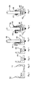
- FIG. 3 is a structural fixing of the female profile using a screw
- FIG. 4 is glass packing on the female profile (minimum 2 per glass panel);
- FIG. 5 is a glass panel (suitable to the frame size) placed over the female profile
- FIG. 6 is the horizontal leg of the male profile introduced through the gap between the upper leg and the lower leg of the female profile and the vertical leg of the male profile is tilted outward on its built-in fulcrum to engage the lock, then wedges are introduced to keep the lock engaged so that glass panel is locked in position;
- FIG. 6A is a perspective view of the self-lock glazing system showing the spacers
- FIG. 6B is a perspective view of the self-lock glazing system showing the wedges
- FIG. 7 is a view of grooved rubber beadings which are introduced in between the gaps of profiles from both sides of the glass panel;
- FIG. 7A is a perspective view of the self-lock glazing system with glass panel in position and the rubber beadings are introduced;
- FIG. 8 is a side view of the mechanism of the glazing system.
- FIG. 9 are details of the locking tips of FIG. 8 .
- the self-lock glazing system consists of two extruded aluminum profiles, a male profile 11 , FIG. 2A and a female profile 12 , FIG. 1A as described in the succeeding paragraphs, designed in such a way to create a secure space for keeping glass panels safely and tightly in position.
- the important aspect of the invention is that when a glass panel 99 , FIG. 7 is placed on the upper leg 70 of the female profile 12 and the male profile 11 is inserted and rubber beadings 97 , 98 are forced in (by hand) between the said glass panel 99 and the profiles 12 , 11 respectively creates outward forces F, FIG. 8 on the vertical tips of the said profiles (forcing them apart).
- the self-lock glazing system comprising:
- a female profile 12 FIG. 1A
- the female profile 12 is a right angled profile having a lower leg 69 as base, an upper leg 70 and an upward vertical leg 68 .
- the upper leg 70 is the horizontal cantilever extension from the lower half portion of the vertical leg 68 .
- the vertical leg 68 originates from the horizontal lower leg 69 at the base and has a vertical face 35 which ends at about three-fourth the height of the vertical leg 68 to join an inclined surface 34 which terminates at the horizontal tip 33 with adjoining vertical face 67 .
- the vertical face 67 acts as the link for transfer of forces between the glass panel 99 , FIG. 5 and the female profile 12 and also helps to retain the rubber beading.
- the vertical face 67 is followed by a horizontal face 66 below that ends to a sloping face 65 which leads to the inside wall 64 of the vertical leg 68 that extends down to form a groove 60 .
- the said groove 60 comprises an upper projection 63 , an upper recess 62 , followed by the vertical wall 61 which is parallel to the exterior wall 35 , a lower recess 59 and a bottom projection 58 .
- the bottom projection 58 is followed by another vertical face 57 that curves down to join the upper face 56 of the upper leg 70 .
- the upper leg 70 which is the horizontal cantilever extension from the lower half portion of the vertical leg 68 , has an upper flat surface formed by 56 and 54 and a groove 55 in between, and this leg 70 terminates approximately at two-thirds of the length of the lower leg 69 at tip 53 and its bottom has a downwardly sloping protrusion 52 with a female locking tip 71 with a mating face 51 followed by an upper horizontal surface 50 that curves down to the vertical wall 49 to form the locking chamber facing downward to the gap formed by the remaining portion of the inside wall 49 and the adjacent upper surface 48 up to 42 of the lower leg 69 ; this gap provides access to the said locking chamber.
- the said vertical faces 67 , 64 , 57 and 49 are all in a same straight line and defines the inside wall of the said female profile 12 .
- the recess formed by the sloped face 65 is for accommodating the allowances provided in the grooved rubber beadings.
- the top surface of the lower leg 69 is flat in general, and this top surface starts with a horizontal surface 48 adjacent to the inner vertical wall 49 and this horizontal surface 48 defines the general level of the top surface.
- the horizontal surface 42 at the other end plays a vital role in the system since it acts as the base for acting the built-in fulcrum 18 in the said male profile 11 .
- the upper surfaces 48 and 42 of the lower leg 69 have two lower horizontal faces 46 and 44 in between with a ‘v’ shaped groove 45 at its centre.
- the recessed surface 46 is connected to the surface 48 with an inclined surface 47 .
- the horizontal recessed surface 44 is connected with the surface 42 by an inclined surface 43 .
- the ‘v’-shaped groove 45 at the centre acts as a guidance for drilling holes for countersunk screws for fastening the female profile 12 to the structure.
- the ‘v’-shaped grooves 45 and 55 are required to ensure precision and accuracy of the installation of the glazing system and also to make drilling easier and to the point.
- a vertical face 41 goes down to the bottom surface of the horizontal leg 69 and this vertical surface 41 comes in the same line with the outer surface 15 of the said male profile 11 when the system is engaged.
- the bottom surface of the lower leg of the said female profile 12 has two symmetrical projections 36 and 40 at the ends with recess 38 at centre for proper seating.
- the recess 38 is connected to projection 36 and 40 with inclined surfaces 37 and 39 respectively.
- the said male profile 11 is an acute angled profile consisting of a horizontal leg 72 with a locking tip 73 at one end and vertical leg 74 at the other end.
- the horizontal leg 72 is the base with a lower surface 19 starting from the lower face 20 of the locking tip 73 , and ends with the built-in fulcrum 18 with an adjoining recess formed by vertical face 17 and a horizontal face 16 .
- the vertical leg 74 starts from the said recess with a surface 15 inclined forward and ends at another inclined face 14 which is further inclined inward to join the horizontal tip 13 .
- the locking tip 73 comprising an upward sloping surface 20 turns to form another upward sloping surface 21 , and an adjoining dropping down face 22 combines to form a unique shape to the locking tip 73 .
- the upper surface 23 of the horizontal leg 72 curves upward to join the inner vertical wall 24 which extends up to a groove 75 .
- the said groove comprising a lower projection 25 , an upper projection 29 , a lower recess 26 , an upper recess 28 with a vertical wall 27 that is parallel to the exterior wall 15 , a top projection 29 , joins the interior wall which slopes upward forming an inclined surface 30 which terminates at the horizontal surface 31 .
- the horizontal surface 31 ends to a vertical face 32 that joins the horizontal tip 13 .
- the horizontal tip 13 together with a vertical surface 32 and a bottom surface 31 helps to retain the rubber beadings.
- the mechanism functions when a glass panel 99 is positioned on packing 96 over the upper leg 70 of the said female profile with spacers 94 between the vertical leg 68 of the said female profile 12 and the said glass panel 99 , and then inserting the horizontal leg 72 of the said male profile 11 with its locking tip 73 facing upward into the gap between the lower leg 69 and upper legs 70 of the said female profile, then engaging the locking tips of both male and female profiles by tilting the said male profile 11 on its built-in fulcrum 18 by pulling the vertical leg 74 outward and introducing the wedges 95 into the space so created between the said glass panel 99 and the said vertical tip 32 of the said male profile 11 to keep the locks engaged and thus the said glass panel 99 locked in the system; the mechanism further tightens its grip on the edges of the locked glass panel 99 when the spacers 94 and wedges 95 are replaced by rubber beadings 97 and 98 of appropriate resilience which enables the said glass panel 99 to remain in an equilibrium throughout the life of the beading.
- the vertical plane passing through the centre of the glass panel 99 will intersect both the male profile 11 and female profile 12 , and also intersect the gap of the female profile 12 and the leg 72 of the male profile 11 . Then the horizontal tip 33 of the vertical leg 68 of the said female profile 12 and the horizontal tip 13 of the vertical leg 74 of the said male profile 11 are located at the same height when the glass panel 99 is positioned and the lock is engaged by tilting the said male profile 11 on its built-in fulcrum 18 by pulling the vertical leg 74 outward and introducing the wedges 95 into the space so created between the said glass panel 99 and the said vertical tip 32 of the said male profile 11 to keep the locks engaged and thus the said glass panel 99 locked in the system.
- the locking system functions due to the combination of a pair of hooking tips and the fulcrum built in the legs of the male and female profiles mating in the locking chamber while retaining the pivotal mating profile (male) firmly in position and the glass panel which is under the grip of the said vertical tips are eventually remain locked.
- the pre-determined variables are the sizing of the glass panel and that of the rubber beading. In this arrangement any external forces applied due to conditions like wind or vibrations caused by physical movements—whose action may act to dislodge the glass from its set position—only acts to further tighten the fastening mechanism of the system to arrest the glass panel in position.
Landscapes
- Engineering & Computer Science (AREA)
- Civil Engineering (AREA)
- Structural Engineering (AREA)
- Securing Of Glass Panes Or The Like (AREA)
- Glass Compositions (AREA)
- Liquid Crystal (AREA)
- Seal Device For Vehicle (AREA)
- Joining Of Glass To Other Materials (AREA)
- Mutual Connection Of Rods And Tubes (AREA)
- Wing Frames And Configurations (AREA)
Abstract
Description
| TABLE | ||
| PATENT NO. | TITLE | ISSUE DATE |
| 3,774,363 | Glazing Window or Windscreen Openings, Particularly | Nov. 27, 1973 |
| in Vehicle Bodies | ||
| 3,881,290 | Glazed Impervious Sheet Assembly and Method of | May 06, 1975 |
| Glazing | ||
| 4,689,933 | Thermally Insulated Window Sash Construction for a | Sep. 01, 1987 |
| Casement Window | ||
| DE2614803 | GLASFALZLEISTE | Oct. 27, 1977 |
| JP10184208 | Fitting to Which Glass and the Like can be Easily | Jul. 14, 1998 |
| Attached/Detached | ||
| JP11256942 | Glazing Gasket | Sep. 21, 1999 |
| UK2237600 | Preventing Removal of Glazing Bead | May 08, 1991 |
Claims (10)
Priority Applications (5)
| Application Number | Priority Date | Filing Date | Title |
|---|---|---|---|
| US12/261,891 US8621793B2 (en) | 2003-07-30 | 2008-10-30 | Glazing system |
| US14/148,188 US20140115982A1 (en) | 2003-07-30 | 2014-01-06 | Glazing system |
| US14/327,961 US9683402B2 (en) | 2004-07-15 | 2014-07-10 | Glazing system with thermal break |
| US14/491,229 US9797185B2 (en) | 2004-07-15 | 2014-09-19 | Self-locking handrail system |
| US14/613,766 US9540861B2 (en) | 2004-07-15 | 2015-02-04 | Multi tensioned composite profile |
Applications Claiming Priority (5)
| Application Number | Priority Date | Filing Date | Title |
|---|---|---|---|
| AE242/2003 | 2003-07-30 | ||
| AE24203 | 2003-07-30 | ||
| US10/566,536 US20060185273A1 (en) | 2003-07-30 | 2004-07-15 | Glazing system |
| PCT/IB2004/002298 WO2005010310A1 (en) | 2003-07-30 | 2004-07-15 | Glazing system |
| US12/261,891 US8621793B2 (en) | 2003-07-30 | 2008-10-30 | Glazing system |
Related Parent Applications (5)
| Application Number | Title | Priority Date | Filing Date |
|---|---|---|---|
| PCT/IB2004/002298 Continuation WO2005010310A1 (en) | 2003-07-30 | 2004-07-15 | Glazing system |
| PCT/IB2004/002298 Continuation-In-Part WO2005010310A1 (en) | 2003-07-30 | 2004-07-15 | Glazing system |
| US10/566,536 Continuation US20060185273A1 (en) | 2003-07-30 | 2004-07-15 | Glazing system |
| US10/566,536 Continuation-In-Part US20060185273A1 (en) | 2003-07-30 | 2004-07-15 | Glazing system |
| US11/566,536 Continuation-In-Part US8789856B2 (en) | 2006-12-04 | 2006-12-04 | Apparatus and method for holding a cover in a closed orientation |
Related Child Applications (1)
| Application Number | Title | Priority Date | Filing Date |
|---|---|---|---|
| US14/148,188 Continuation US20140115982A1 (en) | 2003-07-30 | 2014-01-06 | Glazing system |
Publications (2)
| Publication Number | Publication Date |
|---|---|
| US20090113826A1 US20090113826A1 (en) | 2009-05-07 |
| US8621793B2 true US8621793B2 (en) | 2014-01-07 |
Family
ID=34084999
Family Applications (3)
| Application Number | Title | Priority Date | Filing Date |
|---|---|---|---|
| US10/566,536 Abandoned US20060185273A1 (en) | 2003-07-30 | 2004-07-15 | Glazing system |
| US12/261,891 Expired - Fee Related US8621793B2 (en) | 2003-07-30 | 2008-10-30 | Glazing system |
| US14/148,188 Abandoned US20140115982A1 (en) | 2003-07-30 | 2014-01-06 | Glazing system |
Family Applications Before (1)
| Application Number | Title | Priority Date | Filing Date |
|---|---|---|---|
| US10/566,536 Abandoned US20060185273A1 (en) | 2003-07-30 | 2004-07-15 | Glazing system |
Family Applications After (1)
| Application Number | Title | Priority Date | Filing Date |
|---|---|---|---|
| US14/148,188 Abandoned US20140115982A1 (en) | 2003-07-30 | 2014-01-06 | Glazing system |
Country Status (18)
| Country | Link |
|---|---|
| US (3) | US20060185273A1 (en) |
| EP (1) | EP1651838B1 (en) |
| JP (1) | JP4648314B2 (en) |
| CN (1) | CN1829849B (en) |
| AT (1) | ATE506517T1 (en) |
| AU (1) | AU2004259362B2 (en) |
| BR (1) | BRPI0412533A (en) |
| CA (1) | CA2534089C (en) |
| CY (1) | CY1111820T1 (en) |
| DE (1) | DE602004032348D1 (en) |
| DK (1) | DK1651838T3 (en) |
| ES (1) | ES2365336T3 (en) |
| PL (1) | PL1651838T3 (en) |
| PT (1) | PT1651838E (en) |
| RU (1) | RU2006103235A (en) |
| SI (1) | SI1651838T1 (en) |
| WO (1) | WO2005010310A1 (en) |
| ZA (1) | ZA200600807B (en) |
Cited By (12)
| Publication number | Priority date | Publication date | Assignee | Title |
|---|---|---|---|---|
| US20140363601A1 (en) * | 2012-01-06 | 2014-12-11 | Saint-Gobain Glass France | Glazing unit equipped with peripheral sealing means and its manufacturing process |
| US9151056B2 (en) * | 2008-04-17 | 2015-10-06 | Konvin Associates, L.P. | Dual glazing panel system |
| US9540861B2 (en) | 2004-07-15 | 2017-01-10 | City Glass & Glazing (P) Ltd. | Multi tensioned composite profile |
| US9683402B2 (en) | 2004-07-15 | 2017-06-20 | City Glass & Glazing (P) Ltd. | Glazing system with thermal break |
| US20170198733A1 (en) * | 2016-01-08 | 2017-07-13 | The Boeing Company | Mounting clip and related methods |
| US9903309B2 (en) | 2013-03-14 | 2018-02-27 | Mahle International Gmbh | Welded piston assembly |
| US20190032393A1 (en) * | 2016-02-11 | 2019-01-31 | Kill Industries Ltd. | Glazing profiles with seamless appearance and method of use |
| US20190136606A1 (en) * | 2016-05-02 | 2019-05-09 | Wlodzimierz Grobelny | Window installation apparatus |
| US10415302B2 (en) | 2018-01-08 | 2019-09-17 | Pgt Innovations, Inc. | Window setting block |
| US10458130B2 (en) | 2018-02-01 | 2019-10-29 | Oldcastle Buildingenvelope, Inc. | Demountable wall system and method |
| US11643866B1 (en) * | 2020-12-29 | 2023-05-09 | Andersen Corporation | Retention clip assemblies, retention systems and methods |
| US20230151678A1 (en) * | 2021-11-12 | 2023-05-18 | Riot Glass LLC | Security panel mounting system |
Families Citing this family (23)
| Publication number | Priority date | Publication date | Assignee | Title |
|---|---|---|---|---|
| DE602004032348D1 (en) | 2003-07-30 | 2011-06-01 | Century Glass Llc | GLAZING SYSTEM |
| DE102005054721A1 (en) * | 2005-11-17 | 2007-05-24 | Richard Fritz Gmbh + Co. Kg | disc unit |
| US8056289B1 (en) * | 2008-04-17 | 2011-11-15 | Konvin Associates Ltd. | Dual glazing panel system |
| JP5190643B2 (en) * | 2008-05-28 | 2013-04-24 | コマニー株式会社 | Glass panel mounting structure |
| US8042316B2 (en) * | 2009-01-15 | 2011-10-25 | Lg Chem, Ltd. | Fireproof door |
| US9528266B2 (en) | 2009-04-17 | 2016-12-27 | Konvin Associates, L.P. | Dual glazing panel system |
| DE202010016189U1 (en) * | 2010-12-06 | 2011-02-17 | Bangratz, René, Dipl.-Ing. | glazing |
| WO2012107259A1 (en) * | 2011-02-09 | 2012-08-16 | Assa Abloy Entrance Systems Ab | Blast protection door |
| WO2013048354A1 (en) | 2011-09-26 | 2013-04-04 | Bts Alümi̇nyum Metal Pvc Aksesuar Sanayi̇ Ve Ti̇caret Li̇mi̇ted Şi̇rketi̇ | Glass support mechanism |
| CN103206149A (en) * | 2012-01-12 | 2013-07-17 | 昶鑫企业有限公司 | sliding door leaf |
| US8955270B2 (en) | 2012-05-16 | 2015-02-17 | Olmos Scofield, Llc | Window assemblies including bronze elements |
| US8683775B1 (en) * | 2012-09-07 | 2014-04-01 | Guardian Industries Corp. | Spacer system for installing vacuum insulated glass (VIG) window unit in window frame designed to accommodate thicker IG window unit |
| US9315986B2 (en) * | 2013-02-20 | 2016-04-19 | Freeman Capital Company | Panel support |
| US9074413B1 (en) * | 2014-07-10 | 2015-07-07 | C.R. Laurence Co., Inc. | Rail, stile, mullion, door and wall jamb assemblies for framing glass doors and wall partitions |
| AU2016203546B2 (en) * | 2015-05-29 | 2021-07-15 | Azuma Design Pty Limited | A frame to receive a mesh panel |
| CN105105532B (en) * | 2015-06-17 | 2017-09-19 | 厦门金牌厨柜股份有限公司 | Kitchen cabinet with functions of child lock |
| CN105064870B (en) * | 2015-08-17 | 2017-03-01 | 王兴民 | A kind of holding Combined-type window with card cloth mechanism |
| AU2016100296B4 (en) * | 2016-03-18 | 2017-02-23 | Anhui Maygood Rv Accessories Co., Ltd. | Window mounting system and method |
| ES2592809A1 (en) * | 2016-07-21 | 2016-12-01 | Oscar Torrabias Cantal | Structural element for fixing glass partitions (Machine-translation by Google Translate, not legally binding) |
| GB2555473A (en) * | 2016-10-31 | 2018-05-02 | Zucker John | Frame assembly for sheet material |
| CN109515619A (en) * | 2018-11-01 | 2019-03-26 | 江西朝阳机械有限公司 | A kind of cabin for boat door and window that anticollision performance is strong |
| CN112177456B (en) * | 2020-10-07 | 2024-08-30 | 桂林优利特医疗电子有限公司 | A locking handle door buckle |
| CN113338767B (en) * | 2021-06-16 | 2023-08-25 | 浙江东方大港大河工程塑料有限公司 | PVC profile convenient for fixing glass |
Citations (25)
| Publication number | Priority date | Publication date | Assignee | Title |
|---|---|---|---|---|
| US2304423A (en) * | 1940-02-26 | 1942-12-08 | American Tubular Elevator Comp | Metal window sash |
| US3455080A (en) * | 1964-09-25 | 1969-07-15 | Goodrich Co B F | Plastic extrusions,methods of using the same,and structures formed therewith |
| US3774363A (en) * | 1971-05-10 | 1973-11-27 | Creators Ltd | Glazing window or windscreen openings, particularly in vehicle bodies |
| US3881290A (en) * | 1974-04-15 | 1975-05-06 | Gen Electric | Glazed impervious sheet assembly and method of glazing |
| DE2614803A1 (en) | 1976-04-06 | 1977-10-27 | Syco Prod Entwicklungs Gmbh | Window glazing rebate batten - has U:bent ended spring guide sliding in groove with sawtoothed serration locking on frame teeth |
| US4524978A (en) * | 1983-08-31 | 1985-06-25 | Ampat/Midwest Corp. | Simulated structural gasket |
| US4612743A (en) * | 1984-05-24 | 1986-09-23 | Saelzer Heinrich | Frame construction and profile sections forming same |
| US4689933A (en) * | 1984-07-20 | 1987-09-01 | Winchester Industries, Inc. | Thermally insulated window sash construction for a casement window |
| GB2237600A (en) | 1989-10-30 | 1991-05-08 | Fios Window Group Ltd | Preventing removal of glazing bead |
| US5692349A (en) * | 1995-12-01 | 1997-12-02 | Concept Guillemet Inc. | Molded window frame free of fasteners |
| US5713159A (en) * | 1994-12-14 | 1998-02-03 | Dominion Plastics Inc. | Multi part plastic lineal |
| US5768837A (en) * | 1994-02-21 | 1998-06-23 | Sjoeholm; Jarmo | Profile structure for glazing |
| JPH10184208A (en) | 1996-12-19 | 1998-07-14 | Nanbu Kasei Kk | Fitting to which glass and the like can be easily attached/ detached |
| JPH11256942A (en) | 1998-03-16 | 1999-09-21 | Sankyo Alum Ind Co Ltd | Glazing gasket |
| US20020011040A1 (en) * | 2000-07-31 | 2002-01-31 | Toyoda Gosei Co., Ltd. | Window molding assembly |
| US20030070371A1 (en) * | 2001-10-11 | 2003-04-17 | Kobrehel Michael D. | Glazing assembly for window assembly |
| US20030159374A1 (en) * | 2000-02-19 | 2003-08-28 | Burgess Alan David | Methods of making windows and windows made thereby |
| US20040231255A1 (en) * | 2003-05-19 | 2004-11-25 | Silver Line Building Products Corp. | Method of glazing insulated sash frame |
| US6848225B2 (en) * | 2002-06-12 | 2005-02-01 | Normand Lapierre | Condensation evacuating window sill |
| WO2005010310A1 (en) | 2003-07-30 | 2005-02-03 | Century Glass L.L.C. | Glazing system |
| US20050055906A1 (en) * | 2003-08-18 | 2005-03-17 | Ken Barnard | Garage door window frame and method of installation |
| US20050246980A1 (en) * | 2004-05-05 | 2005-11-10 | Gonzalo Montero | Window system |
| US7040062B2 (en) * | 2001-06-07 | 2006-05-09 | Arpal Aluminum Ltd. | Dismantable protective window |
| US20060143996A1 (en) * | 2004-12-30 | 2006-07-06 | Jorge Alvarado | Universal fenestration cap system and method |
| US7621082B2 (en) * | 2004-03-03 | 2009-11-24 | Deceuninck North America, Llc | Window assembly having an outer sash frame supporting a removable inner sub-sash frame bonded to insulated glass panels |
Family Cites Families (4)
| Publication number | Priority date | Publication date | Assignee | Title |
|---|---|---|---|---|
| US3155205A (en) * | 1962-04-09 | 1964-11-03 | E K Geyser Company | Metal window sash |
| JPH034717Y2 (en) * | 1985-05-31 | 1991-02-06 | ||
| US6003277A (en) * | 1997-04-15 | 1999-12-21 | Newell Industrial Corporation | Co-extruded integrally reinforced cellular PVC window sash |
| US6318037B1 (en) * | 1998-08-21 | 2001-11-20 | Thermoform A/S | Window frame |
-
2004
- 2004-07-15 DE DE602004032348T patent/DE602004032348D1/en not_active Expired - Lifetime
- 2004-07-15 JP JP2006521680A patent/JP4648314B2/en not_active Expired - Lifetime
- 2004-07-15 CN CN200480021835XA patent/CN1829849B/en not_active Expired - Lifetime
- 2004-07-15 AT AT04743959T patent/ATE506517T1/en active
- 2004-07-15 DK DK04743959.1T patent/DK1651838T3/en active
- 2004-07-15 SI SI200431711T patent/SI1651838T1/en unknown
- 2004-07-15 BR BRPI0412533-9A patent/BRPI0412533A/en not_active IP Right Cessation
- 2004-07-15 US US10/566,536 patent/US20060185273A1/en not_active Abandoned
- 2004-07-15 WO PCT/IB2004/002298 patent/WO2005010310A1/en not_active Ceased
- 2004-07-15 EP EP04743959A patent/EP1651838B1/en not_active Expired - Lifetime
- 2004-07-15 AU AU2004259362A patent/AU2004259362B2/en not_active Expired
- 2004-07-15 ZA ZA200600807A patent/ZA200600807B/en unknown
- 2004-07-15 RU RU2006103235/03A patent/RU2006103235A/en unknown
- 2004-07-15 PL PL04743959T patent/PL1651838T3/en unknown
- 2004-07-15 CA CA2534089A patent/CA2534089C/en not_active Expired - Lifetime
- 2004-07-15 ES ES04743959T patent/ES2365336T3/en not_active Expired - Lifetime
- 2004-07-15 PT PT04743959T patent/PT1651838E/en unknown
-
2008
- 2008-10-30 US US12/261,891 patent/US8621793B2/en not_active Expired - Fee Related
-
2011
- 2011-07-20 CY CY20111100720T patent/CY1111820T1/en unknown
-
2014
- 2014-01-06 US US14/148,188 patent/US20140115982A1/en not_active Abandoned
Patent Citations (25)
| Publication number | Priority date | Publication date | Assignee | Title |
|---|---|---|---|---|
| US2304423A (en) * | 1940-02-26 | 1942-12-08 | American Tubular Elevator Comp | Metal window sash |
| US3455080A (en) * | 1964-09-25 | 1969-07-15 | Goodrich Co B F | Plastic extrusions,methods of using the same,and structures formed therewith |
| US3774363A (en) * | 1971-05-10 | 1973-11-27 | Creators Ltd | Glazing window or windscreen openings, particularly in vehicle bodies |
| US3881290A (en) * | 1974-04-15 | 1975-05-06 | Gen Electric | Glazed impervious sheet assembly and method of glazing |
| DE2614803A1 (en) | 1976-04-06 | 1977-10-27 | Syco Prod Entwicklungs Gmbh | Window glazing rebate batten - has U:bent ended spring guide sliding in groove with sawtoothed serration locking on frame teeth |
| US4524978A (en) * | 1983-08-31 | 1985-06-25 | Ampat/Midwest Corp. | Simulated structural gasket |
| US4612743A (en) * | 1984-05-24 | 1986-09-23 | Saelzer Heinrich | Frame construction and profile sections forming same |
| US4689933A (en) * | 1984-07-20 | 1987-09-01 | Winchester Industries, Inc. | Thermally insulated window sash construction for a casement window |
| GB2237600A (en) | 1989-10-30 | 1991-05-08 | Fios Window Group Ltd | Preventing removal of glazing bead |
| US5768837A (en) * | 1994-02-21 | 1998-06-23 | Sjoeholm; Jarmo | Profile structure for glazing |
| US5713159A (en) * | 1994-12-14 | 1998-02-03 | Dominion Plastics Inc. | Multi part plastic lineal |
| US5692349A (en) * | 1995-12-01 | 1997-12-02 | Concept Guillemet Inc. | Molded window frame free of fasteners |
| JPH10184208A (en) | 1996-12-19 | 1998-07-14 | Nanbu Kasei Kk | Fitting to which glass and the like can be easily attached/ detached |
| JPH11256942A (en) | 1998-03-16 | 1999-09-21 | Sankyo Alum Ind Co Ltd | Glazing gasket |
| US20030159374A1 (en) * | 2000-02-19 | 2003-08-28 | Burgess Alan David | Methods of making windows and windows made thereby |
| US20020011040A1 (en) * | 2000-07-31 | 2002-01-31 | Toyoda Gosei Co., Ltd. | Window molding assembly |
| US7040062B2 (en) * | 2001-06-07 | 2006-05-09 | Arpal Aluminum Ltd. | Dismantable protective window |
| US20030070371A1 (en) * | 2001-10-11 | 2003-04-17 | Kobrehel Michael D. | Glazing assembly for window assembly |
| US6848225B2 (en) * | 2002-06-12 | 2005-02-01 | Normand Lapierre | Condensation evacuating window sill |
| US20040231255A1 (en) * | 2003-05-19 | 2004-11-25 | Silver Line Building Products Corp. | Method of glazing insulated sash frame |
| WO2005010310A1 (en) | 2003-07-30 | 2005-02-03 | Century Glass L.L.C. | Glazing system |
| US20050055906A1 (en) * | 2003-08-18 | 2005-03-17 | Ken Barnard | Garage door window frame and method of installation |
| US7621082B2 (en) * | 2004-03-03 | 2009-11-24 | Deceuninck North America, Llc | Window assembly having an outer sash frame supporting a removable inner sub-sash frame bonded to insulated glass panels |
| US20050246980A1 (en) * | 2004-05-05 | 2005-11-10 | Gonzalo Montero | Window system |
| US20060143996A1 (en) * | 2004-12-30 | 2006-07-06 | Jorge Alvarado | Universal fenestration cap system and method |
Cited By (21)
| Publication number | Priority date | Publication date | Assignee | Title |
|---|---|---|---|---|
| US9540861B2 (en) | 2004-07-15 | 2017-01-10 | City Glass & Glazing (P) Ltd. | Multi tensioned composite profile |
| US9683402B2 (en) | 2004-07-15 | 2017-06-20 | City Glass & Glazing (P) Ltd. | Glazing system with thermal break |
| US9797185B2 (en) | 2004-07-15 | 2017-10-24 | City Glass & Glazing (P) Ltd. | Self-locking handrail system |
| US9151056B2 (en) * | 2008-04-17 | 2015-10-06 | Konvin Associates, L.P. | Dual glazing panel system |
| US9695627B2 (en) * | 2012-01-06 | 2017-07-04 | Saint-Gobain Glass France | Glazing unit equipped with peripheral sealing means and its manufacturing process |
| US20140363601A1 (en) * | 2012-01-06 | 2014-12-11 | Saint-Gobain Glass France | Glazing unit equipped with peripheral sealing means and its manufacturing process |
| US9903309B2 (en) | 2013-03-14 | 2018-02-27 | Mahle International Gmbh | Welded piston assembly |
| US20170198733A1 (en) * | 2016-01-08 | 2017-07-13 | The Boeing Company | Mounting clip and related methods |
| US10273991B2 (en) * | 2016-01-08 | 2019-04-30 | The Boeing Company | Mounting clip and related methods |
| US10577855B2 (en) * | 2016-02-11 | 2020-03-03 | Klil Industries Ltd | Glazing profiles with seamless appearance and method of use |
| US20190032393A1 (en) * | 2016-02-11 | 2019-01-31 | Kill Industries Ltd. | Glazing profiles with seamless appearance and method of use |
| US20190136606A1 (en) * | 2016-05-02 | 2019-05-09 | Wlodzimierz Grobelny | Window installation apparatus |
| US10941607B2 (en) * | 2016-05-02 | 2021-03-09 | Wlodzimierz Grobelny | Window installation apparatus |
| US10415302B2 (en) | 2018-01-08 | 2019-09-17 | Pgt Innovations, Inc. | Window setting block |
| US10458130B2 (en) | 2018-02-01 | 2019-10-29 | Oldcastle Buildingenvelope, Inc. | Demountable wall system and method |
| US10669712B2 (en) | 2018-02-01 | 2020-06-02 | Oldcastle Buildingenvelope, Inc. | Demountable wall system and method |
| US11028579B2 (en) | 2018-02-01 | 2021-06-08 | Oldcastle Buildingenvelope, Inc. | Demountable wall system with removable cover |
| US11643866B1 (en) * | 2020-12-29 | 2023-05-09 | Andersen Corporation | Retention clip assemblies, retention systems and methods |
| US11982121B1 (en) | 2020-12-29 | 2024-05-14 | Andersen Corporation | Retention clip assemblies, retention systems and methods |
| US20230151678A1 (en) * | 2021-11-12 | 2023-05-18 | Riot Glass LLC | Security panel mounting system |
| US12467312B2 (en) * | 2021-11-12 | 2025-11-11 | Riot Glass LLC | Security panel mounting system |
Also Published As
| Publication number | Publication date |
|---|---|
| HK1091883A1 (en) | 2007-01-26 |
| PL1651838T3 (en) | 2011-11-30 |
| CY1111820T1 (en) | 2015-10-07 |
| US20140115982A1 (en) | 2014-05-01 |
| ZA200600807B (en) | 2007-05-30 |
| BRPI0412533A (en) | 2006-09-19 |
| CA2534089A1 (en) | 2005-02-03 |
| ATE506517T1 (en) | 2011-05-15 |
| SI1651838T1 (en) | 2011-08-31 |
| DK1651838T3 (en) | 2011-08-01 |
| ES2365336T3 (en) | 2011-09-29 |
| RU2006103235A (en) | 2006-07-10 |
| DE602004032348D1 (en) | 2011-06-01 |
| AU2004259362A1 (en) | 2005-02-03 |
| CN1829849A (en) | 2006-09-06 |
| WO2005010310B1 (en) | 2005-05-06 |
| US20090113826A1 (en) | 2009-05-07 |
| WO2005010310A1 (en) | 2005-02-03 |
| AU2004259362B2 (en) | 2010-06-24 |
| US20060185273A1 (en) | 2006-08-24 |
| JP4648314B2 (en) | 2011-03-09 |
| PT1651838E (en) | 2011-07-15 |
| CA2534089C (en) | 2012-01-03 |
| CN1829849B (en) | 2011-06-15 |
| JP2007500294A (en) | 2007-01-11 |
| EP1651838B1 (en) | 2011-04-20 |
| EP1651838A1 (en) | 2006-05-03 |
Similar Documents
| Publication | Publication Date | Title |
|---|---|---|
| US8621793B2 (en) | Glazing system | |
| US9683402B2 (en) | Glazing system with thermal break | |
| US11136802B2 (en) | Semi-invisible combination for sliding doors which allows the unhindered passage | |
| US20060016137A1 (en) | System for joining mullions to transoms by frontal link | |
| DE69000741D1 (en) | PROFILE ELEMENT FOR DOOR LEAFS. | |
| EP1201868B1 (en) | Spring clip for fastening a glass pane | |
| US3284976A (en) | Door construction | |
| US4432163A (en) | Adjustable mounting system for patio doors and the like | |
| GB2086458A (en) | Double glazing arrangement | |
| GB2159202A (en) | Prefabricated facade | |
| GR1010437B (en) | COMPONENT FOR HOLDING, CLAMPING AND ADJUSTING THE ROOF GLASS PANELS WITHIN A RETAINING PROFILE | |
| JP7061957B2 (en) | Joinery | |
| JP7713351B2 (en) | Fittings | |
| KR102867589B1 (en) | Multi-compressed structure insulation unsecured windows | |
| GB2264742A (en) | Improvements relating to the manufacture and glazing of windows and doors | |
| US2981385A (en) | Insulated metal-framed window sash | |
| IE20010656A1 (en) | Curtain walling | |
| JP2024137105A (en) | Fittings | |
| JP6812211B2 (en) | Ridge mounting structure and mounting method | |
| JP2023082333A (en) | Fittings | |
| JP2021161605A (en) | Fitting | |
| JP2001132344A (en) | Fitting structure of muntin in opening of partition | |
| GB2394982A (en) | Frame parts connected by flanges and grooves | |
| JPH05179864A (en) | Sash frame | |
| GB2416799A (en) | Glazing assembly |
Legal Events
| Date | Code | Title | Description |
|---|---|---|---|
| AS | Assignment |
Owner name: CENTURY GLASS LLC, UNITED ARAB EMIRATES Free format text: ASSIGNMENT OF ASSIGNORS INTEREST;ASSIGNOR:LATHIEF, ARAKKAL A. ABDUL;REEL/FRAME:029761/0880 Effective date: 20130124 |
|
| STCF | Information on status: patent grant |
Free format text: PATENTED CASE |
|
| AS | Assignment |
Owner name: CITY GLASS & GLAZING (P) LTD., INDIA Free format text: ASSIGNMENT OF ASSIGNORS INTEREST;ASSIGNOR:CENTURY GLASS LLC;REEL/FRAME:038639/0506 Effective date: 20131029 |
|
| FEPP | Fee payment procedure |
Free format text: MAINTENANCE FEE REMINDER MAILED (ORIGINAL EVENT CODE: REM.) |
|
| FEPP | Fee payment procedure |
Free format text: SURCHARGE FOR LATE PAYMENT, SMALL ENTITY (ORIGINAL EVENT CODE: M2554) |
|
| MAFP | Maintenance fee payment |
Free format text: PAYMENT OF MAINTENANCE FEE, 4TH YR, SMALL ENTITY (ORIGINAL EVENT CODE: M2551) Year of fee payment: 4 |
|
| FEPP | Fee payment procedure |
Free format text: 7.5 YR SURCHARGE - LATE PMT W/IN 6 MO, SMALL ENTITY (ORIGINAL EVENT CODE: M2555); ENTITY STATUS OF PATENT OWNER: SMALL ENTITY |
|
| MAFP | Maintenance fee payment |
Free format text: PAYMENT OF MAINTENANCE FEE, 8TH YR, SMALL ENTITY (ORIGINAL EVENT CODE: M2552); ENTITY STATUS OF PATENT OWNER: SMALL ENTITY Year of fee payment: 8 |
|
| FEPP | Fee payment procedure |
Free format text: MAINTENANCE FEE REMINDER MAILED (ORIGINAL EVENT CODE: REM.); ENTITY STATUS OF PATENT OWNER: SMALL ENTITY |
|
| LAPS | Lapse for failure to pay maintenance fees |
Free format text: PATENT EXPIRED FOR FAILURE TO PAY MAINTENANCE FEES (ORIGINAL EVENT CODE: EXP.); ENTITY STATUS OF PATENT OWNER: SMALL ENTITY |
|
| STCH | Information on status: patent discontinuation |
Free format text: PATENT EXPIRED DUE TO NONPAYMENT OF MAINTENANCE FEES UNDER 37 CFR 1.362 |