JP5190643B2 - Glass panel mounting structure - Google Patents
Glass panel mounting structure Download PDFInfo
- Publication number
- JP5190643B2 JP5190643B2 JP2008139453A JP2008139453A JP5190643B2 JP 5190643 B2 JP5190643 B2 JP 5190643B2 JP 2008139453 A JP2008139453 A JP 2008139453A JP 2008139453 A JP2008139453 A JP 2008139453A JP 5190643 B2 JP5190643 B2 JP 5190643B2
- Authority
- JP
- Japan
- Prior art keywords
- glass
- frame
- vertical
- fitted
- glass panel
- Prior art date
- Legal status (The legal status is an assumption and is not a legal conclusion. Google has not performed a legal analysis and makes no representation as to the accuracy of the status listed.)
- Active
Links
- 239000011521 glass Substances 0.000 title claims description 220
- 238000005192 partition Methods 0.000 claims description 26
- 239000000463 material Substances 0.000 claims description 20
- 239000011324 bead Substances 0.000 claims description 13
- 238000003780 insertion Methods 0.000 claims description 13
- 230000037431 insertion Effects 0.000 claims description 13
- 239000002184 metal Substances 0.000 claims description 5
- 239000013013 elastic material Substances 0.000 description 2
- 230000001771 impaired effect Effects 0.000 description 2
- 238000000638 solvent extraction Methods 0.000 description 2
- 238000009432 framing Methods 0.000 description 1
- 238000009434 installation Methods 0.000 description 1
Images


Description
本発明はガラスパネルの取付け構造に関するものである。 The present invention relates to a glass panel mounting structure.
間仕切りパネル装置にも色々な形態があり、金属製パネルを用いた構造に限ることなく、ガラスパネルを使用して構成した間仕切りパネル構造も色々知られている。図7、図8は従来のガラス間仕切りパネル装置を示す具体例であり、縦断面と横断面を表している。同図に示すように、ガラス(イ)、(イ)が両面側に嵌っていて、ガラス枠体との間に大きな段差を与えることなくほぼ面一な面を構成している。垂直に起立したスタッド(ロ)、(ロ)間にはガラス枠体が取付けられ、このガラス枠体の両面側に設けているガラス溝(ハ)、(ハ)にガラス(イ)が嵌っている。 There are various types of partition panel devices, and not only a structure using a metal panel, but also a partition panel structure configured using a glass panel is known. FIG. 7 and FIG. 8 are specific examples showing a conventional glass partition panel device, showing a longitudinal section and a transverse section. As shown in the figure, the glasses (a) and (a) are fitted on both sides, and form a substantially flush surface without giving a large step between the glass frame. A glass frame is attached between the vertically standing studs (b) and (b), and the glass (b) is fitted into the glass grooves (c) and (c) provided on both sides of the glass frame. Yes.
ガラス枠体は上桟(ニ)、下桟(ホ)、及び両縦桟(ヘ)、(ヘ)にて枠組され、そして上桟(ニ)と下桟(ホ)の間に2本の中桟(ト)、(ト)を取付けている。中桟(ト)は縦桟側からネジ止めされているが、このように枠組されたガラス枠体はガラス(イ)を嵌めることなく据付られ、該ガラス枠体が取付けられた状態で、最後にガラス(イ)をガラス溝(ハ)に嵌めることが出来る。ここで、枠組されたガラス枠体のガラス溝(ハ)にガラス(イ)を嵌める為に、縦桟(ヘ)、(ヘ)は補助部材(チ)を設けていて、これを取外すことで表面側を開口することが出来る構造としている。 The glass frame is framed by an upper beam (d), a lower beam (e), and both vertical beams (f) and (f), and two frames are placed between the upper beam (d) and the lower beam (e). Middle rail (G) and (G) are installed. The middle beam (g) is screwed from the vertical beam side, but the glass frame framed in this way is installed without fitting the glass (A), and the glass frame is attached in the final state. The glass (I) can be fitted into the glass groove (C). Here, in order to fit the glass (b) into the glass groove (c) of the framed glass frame, the vertical beam (f) and (f) are provided with auxiliary members (chi), and by removing this The surface side can be opened.
そしてガラス枠体はガラス溝(ハ)にゴム等の弾性体(リ)とガスケット(ヌ)を介してガラス(イ)を取付ける構造と成っている為に、ガラス枠体を枠組みし、これを据付した後で該ガラス(イ)をガラス溝(ハ)に嵌めることが出来る。すなわち、ガラス溝(ハ)の内側に弾性体(リ)を設けてガラス(イ)を嵌め、該ガラス(イ)が外れないようにガスケット(ヌ)を取付けている。又、下桟(ホ)のガラス溝(ハ)及び中桟(ト)のガラス溝(ハ)にはガラス(イ)が載る弾性体(リ)を設けている。 And because the glass frame has a structure in which the glass (b) is attached to the glass groove (c) via an elastic body (re) such as rubber and a gasket (nu), the glass frame is framed and this After installation, the glass (I) can be fitted into the glass groove (C). That is, an elastic body (re) is provided inside the glass groove (c) to fit the glass (b), and the gasket (n) is attached so that the glass (b) is not removed. In addition, the glass groove (c) of the lower beam (e) and the glass groove (c) of the middle beam (g) are provided with an elastic body (re) on which the glass (a) is placed.
ところで、床面には床レール(ル)が敷設・固定され、この床レール(ル)に配置されているアジャスター装置(オ)に載って巾木(ワ)が所定の高さに支えられている。巾木(ワ)は門形断面をした長尺材であって、床レール(ル)及びアジャスター装置(オ)を被覆している。そして、該巾木(ワ)の上に前記ガラス枠体が載置され、ガラス枠体の上端は天井レール(カ)と連結している。天井レール(カ)は天井に取着された門形断面の長尺材であり、この天井レール(カ)はガラス枠体の上桟(ニ)の開口に嵌って連結している。 By the way, a floor rail (le) is laid and fixed on the floor, and the baseboard (wa) is supported at a predetermined height on the adjuster device (e) arranged on the floor rail (le). Yes. The baseboard (wa) is a long material having a gate-shaped cross section, and covers the floor rail (le) and the adjuster device (e). And the said glass frame is mounted on this baseboard (wa), and the upper end of the glass frame is connected with the ceiling rail (f). The ceiling rail (f) is a long material with a gate-shaped cross section attached to the ceiling, and the ceiling rail (f) is fitted and connected to the opening of the upper frame (d) of the glass frame.
このように、ガラス(イ)、(イ)・・をガラス枠体の両側に取付けることでほぼ面一になるが、大きな地震が発生した際にガラス枠体が変形し、ガラス(イ)、(イ)・・が破損しないようにガラス溝(ハ)、(ハ)・・には適度なクリアランス(ヨ)、(ヨ)・・を設けている。そのことも一因して、従来のガラス枠体では見付け寸法Aが大きくなり、ガラスパネルの外観が損なわれる。又、ガラス枠体をスタッド(ロ)に固定する為にビス(タ)、(タ)・・を使用している為に、このビス頭が露出しないように目地材(レ)、(レ)・・を嵌めている。従って、目地幅はある程度の寸法が必要であり、従来では5mm〜12mmの幅寸法と成っている。 In this way, the glass (I), (I) ... are almost flush with each other by attaching them to both sides of the glass frame, but when a large earthquake occurs, the glass frame deforms, and the glass (I), (B) Glass grooves (c) and (c) are provided with appropriate clearances (yo) and (yo) to prevent damage. Partly because of this, in the conventional glass frame, the finding dimension A becomes large, and the appearance of the glass panel is impaired. Also, since screws (ta), (ta) ... are used to fix the glass frame to the stud (b), joint materials (le), (le) are used so that this screw head is not exposed.・ ・ Fitting. Therefore, the joint width needs to have a certain size, and conventionally has a width of 5 mm to 12 mm.
特開2004−232311号に係る「二重ガラス間仕切り装置」は、前記図
図7、図8に示すものであり、ガラス枠体の両面側にガラスを嵌めた二重ガラス間仕切りである。しかし、上記のごとき問題も残されている。
The “double glass partition device” according to Japanese Patent Application Laid-Open No. 2004-232311 is shown in FIGS. 7 and 8 and is a double glass partition in which glass is fitted on both sides of a glass frame. However, the above problems still remain.
実開平5−73118号に係る「ガラス間仕切り構造」は、枠体にガラスを嵌込んだガラスパネルであって、一般パネルとの取替え自在で、該パネル面とガラス面との間に大きな段差を生じることのない2重ガラス間仕切り構造である。
すなわち、 両縦桟、上・下桟、必要に応じて中桟を用いて構成した枠体にガラスを嵌込んでガラスパネルとし、下桟にはパネル受けにより支持される支持片を有し、縦桟には目地材と係合してスタッドに固定するための係止片を持ち、該ガラスパネルを、スタッドを間にしてその両側に取着して構成している。
“Glass partition structure” according to Japanese Utility Model Laid-Open No. 5-73118 is a glass panel in which glass is fitted in a frame, and can be replaced with a general panel. This is a double glass partition structure that does not occur.
That is, a glass panel is formed by inserting glass into a frame constructed using both vertical bars, upper and lower bars, and if necessary, a middle bar, and the lower bar has a support piece supported by a panel receiver, The vertical rail has a locking piece for engaging with the joint material and fixing it to the stud, and the glass panel is attached to both sides of the stud with the stud in between.
このガラス間仕切り構造の場合も、枠体では見付け寸法が大きくなり、ガラスパネルの外観が損なわれる。又、枠体をスタッドに固定する為にビスを使用している為に、このビス頭が露出しないように目地材が用いられ、この点もガラスパネルの外観上好ましくない。
このように、従来のガラス間仕切り装置には上記のごとき問題がある。本発明が解決しようとする課題はこれら問題点であり、ガラス間仕切り装置の外観を向上し、スタッドにネジ止めすることなく連結されるガラス間仕切り装置を構成するガラスパネルの取付け構造を提供する。
Thus, the conventional glass partition device has the above-mentioned problems. The problems to be solved by the present invention are these problems, and provide a glass panel mounting structure that improves the appearance of the glass partition device and constitutes the glass partition device connected to the stud without screwing.
本発明に係るガラスパネルはガラス枠にガラスを嵌めたものであり、ここでガラス枠は両縦枠と上枠及び下枠をL形金具を介してネジ止めにより枠組みした構造としている。縦枠は1本の第1枠材と2本の第2枠材とで構成され、第2枠材は第1枠材の両面側に取付けられ、しかも着脱可能な取付け構造としている。そして、この縦枠は外側にスタッドが嵌合する凹部を有し、この凹部を挟んだ両面側にガラス溝を設けている。 The glass panel according to the present invention has a glass frame fitted with glass, and the glass frame has a structure in which both vertical frames, an upper frame, and a lower frame are framed by screws via L-shaped metal fittings. The vertical frame is composed of one first frame member and two second frame members, and the second frame member is attached to both sides of the first frame member and has a detachable attachment structure. And this vertical frame has the recessed part which a stud fits in the outer side, and has provided the glass groove | channel on the both surfaces side which pinched | interposed this recessed part.
ガラス溝は第2枠材を取外すことで開口出来るように成っていて、ガラスは該第2枠材を取外してガラス溝を開口した状態で嵌められる。ガラス枠の下ガラス溝にはガラスを支える為の弾性材を配置し、又左右両側のガラス溝及び上下側のガラス溝には嵌ったガラスがガタ付かないようにガラスビードを取付けている。 The glass groove can be opened by removing the second frame member, and the glass is fitted in a state where the second frame member is removed and the glass groove is opened. An elastic material for supporting the glass is disposed in the lower glass groove of the glass frame, and glass beads are attached so that the glass fitted in the left and right glass grooves and the upper and lower glass grooves does not rattle.
一方、上枠の上側及び下枠の下側にも凹部が設けられ、最下端のガラスパネルの下枠の凹部には門形ガイドが下枠に沿って取付けられ、床レールが外側に嵌っている。そしてスタッドはアジャスターにて適度な高さに支持され、該スタッドにガラスパネルの縦枠がネジ止めされる。同じく、最上端のガラスパネルの上枠の凹部には門形ガイドが上枠に沿って取付けられ、天井レールは門形ガイドの外側に嵌っている。ところで、上記第2枠材は概略L形断面の長尺材であって、概略コ形断面の第1枠材の両端横片には外方向へ延びる2本のアームを有し、この2本のアーム間に形成している空間(挿入溝)に第2枠材の挿入片が挿入されると共に係止して取付けられる。 On the other hand, recesses are also provided on the upper side of the upper frame and on the lower side of the lower frame. A gate-shaped guide is attached along the lower frame to the recess of the lower frame of the lowermost glass panel, and the floor rail is fitted outside. Yes. The stud is supported at an appropriate height by an adjuster, and the vertical frame of the glass panel is screwed to the stud. Similarly, a gate-shaped guide is attached along the upper frame in the recess of the upper frame of the uppermost glass panel, and the ceiling rail is fitted to the outside of the gate-shaped guide. By the way, the second frame material is a long material having a substantially L-shaped cross section, and has two arms extending outwardly on both side lateral pieces of the first frame material having a substantially U-shaped cross section. The insertion piece of the second frame member is inserted into the space (insertion groove) formed between the arms and locked and attached.
ところで、ガラス溝は第2枠材の横片とスタッドの表面に沿って延びる第1枠材の横片との間に形成され、このガラス溝にガラスビードを介してガラスの側端部が嵌入する。そして、ガラス側端と上記アームとの間に適度なクリアランスを残してガラスはガラス溝に嵌っている。スタッドは縦枠の凹部に嵌合してネジ止めにて連結しているが、同時にスタッドと縦枠との間にはマグネットが介在して両者は互いに隙間なく連結している。 By the way, the glass groove is formed between the horizontal piece of the second frame member and the horizontal piece of the first frame member extending along the surface of the stud, and the side end portion of the glass is inserted into the glass groove through the glass bead. To do. The glass fits into the glass groove leaving an appropriate clearance between the glass side end and the arm. The stud is fitted into the recess of the vertical frame and connected by screws, but at the same time, a magnet is interposed between the stud and the vertical frame so that they are connected to each other without any gap.
本発明のガラスパネルはガラス枠の内周に形成したガラス溝にガラスが嵌って構成しているが、ガラス溝底との間には適度なクリアランスを確保しながら見付け寸法は小さくしている。従って、ガラスの透明感や解放感を損なうことなく、該ガラスパネルを取付けて構成されるガラス間仕切り装置の外観意匠は向上する。ガラス枠を構成する縦枠は第1縦材と第2縦材の組合せた構造とし、上記ガラス溝はスタッドを抱え込む第1枠材の横片と第2枠材の横片間に形成され、このガラス溝にガラス側端が嵌ることが出来る為に、上記見付け寸法は小さくなる。 The glass panel of the present invention is configured such that glass is fitted in a glass groove formed on the inner periphery of a glass frame, but the finding dimension is made small while ensuring an appropriate clearance between the glass groove bottom. Therefore, the appearance design of the glass partition device constructed by attaching the glass panel can be improved without impairing the transparency and release feeling of the glass. The vertical frame constituting the glass frame has a structure in which the first vertical member and the second vertical member are combined, and the glass groove is formed between the horizontal piece of the first frame member holding the stud and the horizontal piece of the second frame member, Since the glass side end can be fitted into the glass groove, the above-mentioned finding dimension is reduced.
この第2縦材はその挿入片が第1縦材に形成した挿入溝に嵌って係止されるが、ガラス溝に嵌っている外側ガラスビードを外さない限り第2縦材が外れることはなく、ガラスがガラス溝から外れて落下することはない。そして、縦枠に設けた凹部にスタッドが嵌って該スタッドを抱き込むようにネジ止めにて連結し、しかも、スタッドとマグネットを介して連結される為に隙間の発生はない。従って、従来のようなパネル間に目地空間を形成してスタッドにネジ止めする構造ではない為に、ネジ頭を被覆する為の目地材を目地空間に嵌める必要はなく、その為に目地の幅寸法は小さくなり、ガラス間仕切り装置の外観は向上する。 The second vertical member is inserted and locked in the insertion groove formed in the first vertical member, but the second vertical member does not come off unless the outer glass bead fitted in the glass groove is removed. The glass does not fall off the glass groove. And since a stud fits in the recessed part provided in the vertical frame and it connects by screwing so that this stud may be embraced, and it is connected via a stud and a magnet, there is no gap. Therefore, since the joint space is not formed between the panels and screwed to the stud as in the conventional case, it is not necessary to fit the joint material for covering the screw head in the joint space. The dimensions are reduced and the appearance of the glass partition device is improved.
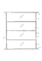
図1はガラス間仕切り装置の正面図であり、4枚のガラスパネル1a,1b,1c,1dを段積みした構造とし、各ガラスパネル1a,1b・・は横長を成して床面2から天井3まで延びている。そして、段積みされたガラスパネル1a,1b・・の両側にはスタッド4,4が起立し、該スタッド4,4を介して隣にも同じく段積みしてガラスパネル1a,1b・・が据付けられる。
FIG. 1 is a front view of a glass partitioning device, in which four glass panels 1a, 1b, 1c, 1d are stacked, and each glass panel 1a, 1b,. It extends to 3. Then,
図2は図1における2段目のガラスパネル1を構成するガラス枠5を示している実施例であり、該ガラス枠5は両縦枠6,6、上枠7、及び下枠8がL形金具9,9・・にて枠組みして構成している。このガラス枠5には2枚のガラスが表側と裏側に嵌められてガラスパネル1となるが、段積みして取付けられたガラス枠5にガラスを嵌めることが出来るように縦枠6,6は1本の第1縦材と2本の第2縦材の3ピース構造と成っている。そして、該第2縦材は取外してガラスを嵌め、嵌めたガラスが外れないように第2縦材を第1縦材に取付けている。
FIG. 2 is an embodiment showing a glass frame 5 constituting the second-stage glass panel 1 in FIG. 1, wherein the glass frame 5 has both
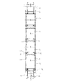
図3はガラスパネル1a,1b・・を4段積み構造とした縦断面図を示している。同図に示しているように、ガラス枠5にはその両面にガラス10,10が嵌められ、その為に、該ガラス枠5の両面側にはガラス溝11,11・・を形成している。そして、下枠8に設けているガラス溝11,11の底には弾性材12,12を取付け、この弾性材12,12にガラス10,10が載っている。
FIG. 3 shows a longitudinal sectional view in which the glass panels 1a, 1b,. As shown in the figure, the glass frame 5 is fitted with
ところで、最下端に位置するガラスパネル1aの下側凹部には下枠8aに沿って門形ガイド13が取付けられ、床に敷設されている床レール15の内側に嵌ってガイドし、該床レール15と下枠8aとの隙間を防止している。そして、ガラスパネル1aは垂直に起立するスタッド4にネジ止めされて取着される。ここで、該スタッド4はアジャスター14にて適度な高さに支持されている。スタッド4への取付けは、ガラスパネル1aのガラス枠5をL形金具9にて枠組みする為のネジが兼用される。勿論、独立して枠組みしたガラスパネル1aをスタッド4に固定することも可能である。そして、ガラスパネル1aの上にはガラスパネル1bが載り、その上にはガラスパネル1cが積み上げられ、さらにその上にはガラスパネル1dが載っている。
By the way, a gate-shaped
これら各ガラスパネル1b,1c,1dも、その縦枠6がスタッド4にネジ止めして取着されている。ガラスパネル1dの上枠7dには凹部が形成され、該凹部には門形ガイドが上枠7dに沿って取着され、そして天井に敷設した天井レール16が嵌合して位置決めされている。この門形ガイドは天井レールが内側へ撓み変形した際の上枠7dとの隙間を防止することが出来る。このように、下段のガラスパネル1aと上段のガラスパネル1dでは、その下枠8aと上枠7dは他のガラスパネル1b,1cの上・下枠とは断面形状が違っている。
Each of these glass panels 1b, 1c, and 1d is also attached with its
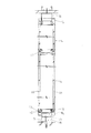
図4は4段積み構造としたガラス間仕切り装置の縦断面図であり、下段と上段にガラスパネル1a,1dを取付けている。その他にはボードに表面材19を貼着したパネル17b,17cが配置されている。ガラスパネル1aの上には中間目地材18が取着され、この中間目地材18にパネル17bの表面材19の先端を係止して連結している。同じく、パネル17bの上には中間目地材18を介してパネル17cが積み上げられ、さらにパネル17cの上にはガラスパネル1dが載置されている。
FIG. 4 is a vertical cross-sectional view of a glass partition device having a four-tier structure, in which glass panels 1a and 1d are attached to the lower and upper stages. In addition,
図5は2枚のガラスパネル1a,1bを段積みしたガラス間仕切り装置の縦断面を表している。この間仕切り装置の下段のガラスパネル1aの高さは大きく、上段のガラスパネル1bの高さは低く成っている。前記図3、図4に示したガラス間仕切り装置の縦断面の場合と同じように、下段のガラスパネル1aの下枠8aに形成した凹部には該下枠8aに沿って門形ガイド13が取付けられ、床面に敷設した床レール15が該門形ガイド13の外側に嵌っている。
FIG. 5 shows a longitudinal section of a glass partition device in which two glass panels 1a and 1b are stacked. The height of the lower glass panel 1a of the partition device is large, and the height of the upper glass panel 1b is low. As in the case of the longitudinal section of the glass partition device shown in FIGS. 3 and 4, the
そして、上段のガラスパネル1bの上枠7bの凹部にも門形ガイドが取付けられ、該門形ガイドの外側には天井レール16が嵌っている。一方、図3、図5に示すガラス間仕切り装置は複数枚のガラスパネル1a,1b・・を段積みして構成した場合であるが、複数のガラスパネル1a,1b・・を段積みすることなく、ガラスパネル1の高さを天井レール16まで届く大きさとし、中間に中桟を縦枠に取付けた構造とすることも可能である。この場合には、中桟の上側と下側にガラス溝を設ける。
A portal guide is also attached to the recess of the upper frame 7b of the upper glass panel 1b, and a
図6はガラスパネル1のスタッドとの連結構造を示す横断面の一部で、ガラス10が嵌るガラス溝を表している。同図の4はスタッドを表し、縦枠6の外側には凹部20が設けられ(図2参照)、この凹部20にスタッド4が嵌合する。すなわち、縦枠6はスタッド4を抱くように配置されると共にネジ止めされ、そしてマグネット21を介して連結されている。
FIG. 6 is a part of a cross section showing a connection structure with the stud of the glass panel 1 and shows a glass groove into which the
ところで、縦枠6は1本の第1縦材22と2本の第2縦材23、23の組合せ構造とし、第2縦材23,23は第1縦材22の両面側に着脱可能に取付けられている。第1縦材22は概略コ形断面の長尺材で、スタッド4の表面に沿って延びる横片24を有し、該横片24には2本のアーム25,26を外方向へ延ばしている。第2縦材23は概略L形断面の長尺材で、横片27と挿入片28を有し、挿入片28は両アーム25、26の間に形成される挿入溝29に嵌っている。
By the way, the
挿入片28は突部30を有し、この突部30はアーム26の先端に形成している掛止部31に係止し、その結果、第2縦材23は外れないようになる。すなわち、ガラス溝11に嵌ったガラス10は内側ガラスビード32と外側ガラスビード33とで挟まれて、第2縦材23の横片27の先端を外方向へ押出す力が作用し、その為に、突部30は掛止部31から離脱することはない。
The
ところで、ガラス10をガラス溝11に嵌める場合には、第2縦材23を取外してガラス溝11を開口した状態で嵌めることが出来る。この場合、ガラス溝11の内側には内側ガラスビード32が取付けられており、ガラス10を嵌めて第2縦材23を取付けた後で外側ガラスビード33をガラス10と横片27との間に嵌め込む。従って、第2縦材23の横片27の先端は外側ガラスビード33が取付けられることで、外方向へ押圧させる力が作用し、その結果、挿入片28の先端はアーム25を押圧し、突部30は掛止部31に係止する。
By the way, when the
ここで、ガラス溝11に嵌ったガラス10の側端はアーム25との間に適度な大きさのクリアランス34を残している。同じく、下枠8のガラス溝11の底に配置した弾性材12に載ったガラス10はその上端は上枠7のガラス溝11に嵌っているが、このガラス溝底との間には十分なクリアランスを有している。
Here, the side edge of the
従って、大きな地震が発生してガラス枠5が変形しても、ガラス溝11に残されているクリアランス34,34・・によってガラス10が割れることはない。一方、スタンド4を間にして連結している縦枠6,6間の目地空間は非常に小さくなり、約2mm程度としている。本発明ではガラス枠5を正面側にてスタッド4にネジ止めする連結構造でない為に、すなわちネジ止めするに必要な目地空間を必要としない為に、十分に小さくすることが出来る。
Therefore, even if a large earthquake occurs and the glass frame 5 is deformed, the
ガラス溝11は縦枠6だけでなく上枠7及び下枠8にも形成され、ガラス上端部及びガラス下端部は上枠7及び下枠8のガラス溝11,11に嵌っている。ただし、上枠7及び下枠8のガラス溝11は縦枠のガラス溝11のように開口することはないが、内側ガラスビード32と外側ガラスビード33に挟まれた状態で嵌合している。
The glass groove 11 is formed not only in the
1 ガラスパネル
2 床面
3 天井
4 スタッド
5 ガラス枠
6 縦枠
7 上枠
8 下枠
9 L形金具
10 ガラス
11 ガラス溝
12 弾性材
13 門形ガイド
14 アジャスター
15 床レール
16 天井レール
17 パネル
18 中間目地材
19 表面材
20 凹部
21 マグネット
22 第1縦材
23 第2縦材
24 横片
25 アーム
26 アーム
27 横片
28 挿入片
29 挿入溝
30 突部
31 掛止部
32 内側ガラスビード
33 外側ガラスビード
34 クリアランス
1
10 Glass
11 Glass groove
12 Elastic material
13 Portal guide
14 Adjuster
15 floor rail
16 Ceiling rail
17 Panel
18 Intermediate joint material
19 Surface material
20 recess
21 Magnet
22 First lumber
23 Second lumber
24 horizontal pieces
25 arms
26 Arm
27 Horizontal pieces
28 Insertion piece
29 Insertion groove
30 protrusions
31 Hook
32 inner glass beads
33 Outer glass bead
34 Clearance
Claims (2)
Priority Applications (2)
| Application Number | Priority Date | Filing Date | Title |
|---|---|---|---|
| JP2008139453A JP5190643B2 (en) | 2008-05-28 | 2008-05-28 | Glass panel mounting structure |
| CN 200910004865 CN101592014B (en) | 2008-05-28 | 2009-01-21 | Glass panel and installation structure for the same |
Applications Claiming Priority (1)
| Application Number | Priority Date | Filing Date | Title |
|---|---|---|---|
| JP2008139453A JP5190643B2 (en) | 2008-05-28 | 2008-05-28 | Glass panel mounting structure |
Publications (2)
| Publication Number | Publication Date |
|---|---|
| JP2009287244A JP2009287244A (en) | 2009-12-10 |
| JP5190643B2 true JP5190643B2 (en) | 2013-04-24 |
Family
ID=41406873
Family Applications (1)
| Application Number | Title | Priority Date | Filing Date |
|---|---|---|---|
| JP2008139453A Active JP5190643B2 (en) | 2008-05-28 | 2008-05-28 | Glass panel mounting structure |
Country Status (2)
| Country | Link |
|---|---|
| JP (1) | JP5190643B2 (en) |
| CN (1) | CN101592014B (en) |
Families Citing this family (1)
| Publication number | Priority date | Publication date | Assignee | Title |
|---|---|---|---|---|
| CN104454834A (en) * | 2014-10-18 | 2015-03-25 | 中山市创科科研技术服务有限公司 | Hollow glass and aluminum frame connecting piece |
Family Cites Families (11)
| Publication number | Priority date | Publication date | Assignee | Title |
|---|---|---|---|---|
| JPS5893174U (en) * | 1981-12-17 | 1983-06-24 | フクビ化学工業株式会社 | Synthetic resin double glazed window frame |
| JP2548673B2 (en) * | 1993-06-03 | 1996-10-30 | トステム株式会社 | Condensate drainage parts for door installation |
| JPH0729111U (en) * | 1993-11-02 | 1995-06-02 | 株式会社桐井製作所 | Spacer for steel wall foundation structure of building |
| JPH09264056A (en) * | 1996-03-29 | 1997-10-07 | Comany Kk | Simple partition and structure between wall surfaces |
| JP3660959B2 (en) * | 2000-06-20 | 2005-06-15 | コクヨ株式会社 | Movable partition wall |
| JP4646453B2 (en) * | 2001-07-16 | 2011-03-09 | コクヨ株式会社 | Partition |
| JP2003105896A (en) * | 2001-09-28 | 2003-04-09 | Comany Inc | Partition apparatus |
| JP2004232311A (en) * | 2003-01-30 | 2004-08-19 | Comany Inc | Double glazing partition device |
| SI1651838T1 (en) * | 2003-07-30 | 2011-08-31 | Century Glass L L C | Glazing system |
| CA2482201C (en) * | 2003-09-23 | 2012-05-29 | Aurele Robin | Apparatus and process for frame manufacture |
| JP4154530B2 (en) * | 2004-09-13 | 2008-09-24 | コクヨ株式会社 | Partition and panel element mounting structure |
-
2008
- 2008-05-28 JP JP2008139453A patent/JP5190643B2/en active Active
-
2009
- 2009-01-21 CN CN 200910004865 patent/CN101592014B/en active Active
Also Published As
| Publication number | Publication date |
|---|---|
| CN101592014A (en) | 2009-12-02 |
| CN101592014B (en) | 2013-02-06 |
| JP2009287244A (en) | 2009-12-10 |
Similar Documents
| Publication | Publication Date | Title |
|---|---|---|
| KR101816686B1 (en) | Bracket unit for installation of external panels for construction and building exterior panel assemblies using the same | |
| US10024093B2 (en) | Shower door guide assembly | |
| KR101950250B1 (en) | Frame assembly bracket | |
| KR101296988B1 (en) | System to join screen partition frame of desk | |
| KR101907132B1 (en) | window frame assembly for curtain wall system | |
| JP5190643B2 (en) | Glass panel mounting structure | |
| JP5176207B2 (en) | Glass mounting structure for glass panels | |
| KR20180071861A (en) | Connecting Structure of Vertical Frame of Door and Glass Member | |
| KR20140047285A (en) | Side sill molding for vehicle | |
| JP2008168975A (en) | Elevator cage mirror device | |
| KR200451348Y1 (en) | Panel fixing structure | |
| KR102098932B1 (en) | Horizontal joiner and Vertical Joiner for chassis combination, and chassis combination structure using the same | |
| JP6411861B2 (en) | Vertical support structure and vertical | |
| WO2017109934A1 (en) | Furniture with top plate | |
| JP2007146505A (en) | Panel of low partition or the like | |
| JP4552195B2 (en) | Corner joint member and corner joint structure of glass partition device | |
| JP4803654B2 (en) | Desk with desktop panel and reinforcing member for desktop panel | |
| JP4171458B2 (en) | Glass partition device | |
| JP6392609B2 (en) | curtain wall | |
| JP2006263380A (en) | Method to install bathroom vanity to wall | |
| JP5061586B2 (en) | Glass panel equipment | |
| JP3514232B2 (en) | Partition panel system | |
| JP5312082B2 (en) | Glass railing and glass railing construction method | |
| KR20180016808A (en) | An apparatus for door frame | |
| JP4365187B2 (en) | Panel support frame |
Legal Events
| Date | Code | Title | Description |
|---|---|---|---|
| A621 | Written request for application examination |
Free format text: JAPANESE INTERMEDIATE CODE: A621 Effective date: 20110511 |
|
| A977 | Report on retrieval |
Free format text: JAPANESE INTERMEDIATE CODE: A971007 Effective date: 20120808 |
|
| A131 | Notification of reasons for refusal |
Free format text: JAPANESE INTERMEDIATE CODE: A131 Effective date: 20120911 |
|
| A521 | Request for written amendment filed |
Free format text: JAPANESE INTERMEDIATE CODE: A523 Effective date: 20120928 |
|
| A521 | Request for written amendment filed |
Free format text: JAPANESE INTERMEDIATE CODE: A523 Effective date: 20121026 |
|
| TRDD | Decision of grant or rejection written | ||
| A01 | Written decision to grant a patent or to grant a registration (utility model) |
Free format text: JAPANESE INTERMEDIATE CODE: A01 Effective date: 20121211 |
|
| A61 | First payment of annual fees (during grant procedure) |
Free format text: JAPANESE INTERMEDIATE CODE: A61 Effective date: 20130115 |
|
| R150 | Certificate of patent or registration of utility model |
Ref document number: 5190643 Country of ref document: JP Free format text: JAPANESE INTERMEDIATE CODE: R150 Free format text: JAPANESE INTERMEDIATE CODE: R150 |
|
| FPAY | Renewal fee payment (event date is renewal date of database) |
Free format text: PAYMENT UNTIL: 20160208 Year of fee payment: 3 |
|
| R250 | Receipt of annual fees |
Free format text: JAPANESE INTERMEDIATE CODE: R250 |
|
| R250 | Receipt of annual fees |
Free format text: JAPANESE INTERMEDIATE CODE: R250 |
|
| R250 | Receipt of annual fees |
Free format text: JAPANESE INTERMEDIATE CODE: R250 |
|
| R250 | Receipt of annual fees |
Free format text: JAPANESE INTERMEDIATE CODE: R250 |
|
| R250 | Receipt of annual fees |
Free format text: JAPANESE INTERMEDIATE CODE: R250 |
|
| R250 | Receipt of annual fees |
Free format text: JAPANESE INTERMEDIATE CODE: R250 |
|
| R250 | Receipt of annual fees |
Free format text: JAPANESE INTERMEDIATE CODE: R250 |
|
| R250 | Receipt of annual fees |
Free format text: JAPANESE INTERMEDIATE CODE: R250 |
|
| R250 | Receipt of annual fees |
Free format text: JAPANESE INTERMEDIATE CODE: R250 |