US8565895B2 - Implantable electrode lead and hydrogel sensor - Google Patents
Implantable electrode lead and hydrogel sensor Download PDFInfo
- Publication number
- US8565895B2 US8565895B2 US13/191,347 US201113191347A US8565895B2 US 8565895 B2 US8565895 B2 US 8565895B2 US 201113191347 A US201113191347 A US 201113191347A US 8565895 B2 US8565895 B2 US 8565895B2
- Authority
- US
- United States
- Prior art keywords
- hydrogel
- electrode lead
- electrode
- water
- implantable
- Prior art date
- Legal status (The legal status is an assumption and is not a legal conclusion. Google has not performed a legal analysis and makes no representation as to the accuracy of the status listed.)
- Expired - Fee Related, expires
Links
- 239000000017 hydrogel Substances 0.000 title claims abstract description 189
- 239000002775 capsule Substances 0.000 claims abstract description 107
- 230000008961 swelling Effects 0.000 claims abstract description 16
- 230000001419 dependent effect Effects 0.000 claims abstract description 12
- XLYOFNOQVPJJNP-UHFFFAOYSA-N water Substances O XLYOFNOQVPJJNP-UHFFFAOYSA-N 0.000 claims description 38
- 238000000034 method Methods 0.000 abstract description 11
- 230000008859 change Effects 0.000 description 8
- 238000011156 evaluation Methods 0.000 description 7
- -1 metacrylamide Chemical compound 0.000 description 7
- 210000001519 tissue Anatomy 0.000 description 6
- 238000003325 tomography Methods 0.000 description 6
- 230000000747 cardiac effect Effects 0.000 description 5
- 238000010438 heat treatment Methods 0.000 description 5
- 230000008901 benefit Effects 0.000 description 4
- 230000007423 decrease Effects 0.000 description 4
- 230000035939 shock Effects 0.000 description 4
- 230000000638 stimulation Effects 0.000 description 4
- 239000000126 substance Substances 0.000 description 4
- 210000001124 body fluid Anatomy 0.000 description 3
- 230000007831 electrophysiology Effects 0.000 description 3
- 238000002001 electrophysiology Methods 0.000 description 3
- 230000005284 excitation Effects 0.000 description 3
- 238000004519 manufacturing process Methods 0.000 description 3
- 210000004165 myocardium Anatomy 0.000 description 3
- 229920003213 poly(N-isopropyl acrylamide) Polymers 0.000 description 3
- VRBFTYUMFJWSJY-UHFFFAOYSA-N 28804-46-8 Chemical compound ClC1CC(C=C2)=CC=C2C(Cl)CC2=CC=C1C=C2 VRBFTYUMFJWSJY-UHFFFAOYSA-N 0.000 description 2
- 229920001244 Poly(D,L-lactide) Polymers 0.000 description 2
- 230000008878 coupling Effects 0.000 description 2
- 238000010168 coupling process Methods 0.000 description 2
- 238000005859 coupling reaction Methods 0.000 description 2
- 229920001477 hydrophilic polymer Polymers 0.000 description 2
- 230000001771 impaired effect Effects 0.000 description 2
- 238000005259 measurement Methods 0.000 description 2
- 238000012986 modification Methods 0.000 description 2
- 230000004048 modification Effects 0.000 description 2
- 229920001432 poly(L-lactide) Polymers 0.000 description 2
- 229920001606 poly(lactic acid-co-glycolic acid) Polymers 0.000 description 2
- 229920000052 poly(p-xylylene) Polymers 0.000 description 2
- 229920000070 poly-3-hydroxybutyrate Polymers 0.000 description 2
- 229920002791 poly-4-hydroxybutyrate Polymers 0.000 description 2
- 229920000728 polyester Polymers 0.000 description 2
- JKNCOURZONDCGV-UHFFFAOYSA-N 2-(dimethylamino)ethyl 2-methylprop-2-enoate Chemical compound CN(C)CCOC(=O)C(C)=C JKNCOURZONDCGV-UHFFFAOYSA-N 0.000 description 1
- HRPVXLWXLXDGHG-UHFFFAOYSA-N Acrylamide Chemical compound NC(=O)C=C HRPVXLWXLXDGHG-UHFFFAOYSA-N 0.000 description 1
- 208000033988 Device pacing issue Diseases 0.000 description 1
- 241001082241 Lythrum hyssopifolia Species 0.000 description 1
- 238000005481 NMR spectroscopy Methods 0.000 description 1
- 238000010521 absorption reaction Methods 0.000 description 1
- 238000004873 anchoring Methods 0.000 description 1
- 230000000712 assembly Effects 0.000 description 1
- 238000000429 assembly Methods 0.000 description 1
- 210000004556 brain Anatomy 0.000 description 1
- 239000004020 conductor Substances 0.000 description 1
- 229920001577 copolymer Polymers 0.000 description 1
- 230000006378 damage Effects 0.000 description 1
- 230000007547 defect Effects 0.000 description 1
- 230000000694 effects Effects 0.000 description 1
- 210000005003 heart tissue Anatomy 0.000 description 1
- 238000003384 imaging method Methods 0.000 description 1
- 230000006698 induction Effects 0.000 description 1
- 239000000463 material Substances 0.000 description 1
- 238000000691 measurement method Methods 0.000 description 1
- 230000007383 nerve stimulation Effects 0.000 description 1
- 210000000653 nervous system Anatomy 0.000 description 1
- 230000003287 optical effect Effects 0.000 description 1
- 238000002559 palpation Methods 0.000 description 1
- 230000010399 physical interaction Effects 0.000 description 1
- 229920000642 polymer Polymers 0.000 description 1
- 230000009467 reduction Effects 0.000 description 1
- 238000009877 rendering Methods 0.000 description 1
- 239000012858 resilient material Substances 0.000 description 1
- 210000005245 right atrium Anatomy 0.000 description 1
- 210000005241 right ventricle Anatomy 0.000 description 1
- 239000000523 sample Substances 0.000 description 1
- 230000000451 tissue damage Effects 0.000 description 1
- 231100000827 tissue damage Toxicity 0.000 description 1
- 238000012546 transfer Methods 0.000 description 1
- 208000003663 ventricular fibrillation Diseases 0.000 description 1
Images


Classifications
-
- A—HUMAN NECESSITIES
- A61—MEDICAL OR VETERINARY SCIENCE; HYGIENE
- A61N—ELECTROTHERAPY; MAGNETOTHERAPY; RADIATION THERAPY; ULTRASOUND THERAPY
- A61N1/00—Electrotherapy; Circuits therefor
- A61N1/02—Details
- A61N1/04—Electrodes
- A61N1/05—Electrodes for implantation or insertion into the body, e.g. heart electrode
-
- A—HUMAN NECESSITIES
- A61—MEDICAL OR VETERINARY SCIENCE; HYGIENE
- A61N—ELECTROTHERAPY; MAGNETOTHERAPY; RADIATION THERAPY; ULTRASOUND THERAPY
- A61N1/00—Electrotherapy; Circuits therefor
- A61N1/02—Details
- A61N1/04—Electrodes
- A61N1/0404—Electrodes for external use
- A61N1/0472—Structure-related aspects
- A61N1/0492—Patch electrodes
- A61N1/0496—Patch electrodes characterised by using specific chemical compositions, e.g. hydrogel compositions, adhesives
-
- A—HUMAN NECESSITIES
- A61—MEDICAL OR VETERINARY SCIENCE; HYGIENE
- A61N—ELECTROTHERAPY; MAGNETOTHERAPY; RADIATION THERAPY; ULTRASOUND THERAPY
- A61N1/00—Electrotherapy; Circuits therefor
- A61N1/02—Details
- A61N1/08—Arrangements or circuits for monitoring, protecting, controlling or indicating
- A61N1/086—Magnetic resonance imaging [MRI] compatible leads
-
- A—HUMAN NECESSITIES
- A61—MEDICAL OR VETERINARY SCIENCE; HYGIENE
- A61N—ELECTROTHERAPY; MAGNETOTHERAPY; RADIATION THERAPY; ULTRASOUND THERAPY
- A61N1/00—Electrotherapy; Circuits therefor
- A61N1/18—Applying electric currents by contact electrodes
- A61N1/32—Applying electric currents by contact electrodes alternating or intermittent currents
- A61N1/36—Applying electric currents by contact electrodes alternating or intermittent currents for stimulation
- A61N1/362—Heart stimulators
- A61N1/37—Monitoring; Protecting
- A61N1/3718—Monitoring of or protection against external electromagnetic fields or currents
Definitions
- One or more embodiments of the invention are based in the field of medical engineering and relates to an implantable electrode lead, and an electrode lead assembly.
- One or more embodiments of the invention furthermore relates to an implantable hydrogel sensor and its use.
- at least one embodiment of the invention relates to a method to determine the temperature of the electrode of an electrode lead, and a method for operating a nuclear magnetic resonance tomograph, and its use.
- Electrodes that are present in a patient's body can cause problems during an examination using a nuclear resonance tomograph.
- atomic nuclei are forced by strong magnetostatic fields to precess about the field direction, and they undergo resonant excitation by high frequency electromagnetic alternating fields. When the alternating fields are shut off, the atomic nuclei return to their original direction; the relaxation times are characteristic for various types of tissue, thereby making exact imaging possible.
- the object of the at least one embodiment of the invention is to provide an implantable electrode lead for the medical application, using which an examination based on nuclear resonance tomography can be performed in a safe, reliable manner.
- an electrode lead of this type should be easy to use and cost effective to manufacture in high-volume production.
- an implantable electrode lead for medical applications.
- implantable refers to a permanent or brief, temporary stay in a patient's body e.g. only for the duration of an examination.
- the electrode lead can be present in a variety of embodiments e.g. it can be a stimulation electrode, in particular for nerve stimulation, a cardiac pacemaker electrode, an ICD electrode, an electrophysiology catheter, or an electrode for measuring brain potentials or the like. The list is not conclusive, as one skilled in the art will appreciate.
- the electrode lead includes a distal section having at least one electrically conductive surface region for receiving electrical signals or for emitting electrical pulses i.e. to transmit electrical energy between the electrode lead and its surroundings.
- the electrically conductive surface region will be referred to as the “electrode”.
- the at least one electrode of the electrode lead is connected to an electrical lead which can be electrically connected, at a proximal end of the electrode lead, to an electrical device e.g. a cardiac pacemaker.
- the surface of the electrode lead is typically electrically insulated, with the exception of the at least one electrode.
- the electrode lead is characterized mainly in that the electrode lead includes at least one hydrogel capsule that is thermally coupled to the electrode, wherein the hydrogel capsule has a wall that is water-permeable at least in sections, the wall forming a cavity containing a hydrogel having a temperature-dependent swelling capacity.
- the wall of the hydrogel capsule is designed such that it can adapt to the volume of the hydrogel, the volume being dependent on the water content. This means that the hydrogel capsule increases in size when the volume of the hydrogel increases, and shrinks when the volume of the hydrogel decreases, without appreciably impairing the change in volume of the hydrogel.
- the wall of the hydrogel capsule is composed e.g.
- each electrode may be thermally coupled to a separate hydrogel capsule.
- only the distal base of the hydrogel capsule is water-permeable.
- the electrode lead or the guide wire itself that is inserted therein contains a water reservoir ( 720 ) that is connected via a diaphragm ( 730 ) or duct to the hydrogel capsule ( 710 ) and so the water-permeable wall is formed, while the rest of the hydrogel capsule is water-impermeable.
- the water content can therefore move between the hydrogel capsule and the water reservoir ( 740 ), and the ratio of the water content can be evaluated accordingly using MRT image evaluation.
- This method offers the advantage that it can also be used in a component, such as the guide wire, that is insulated against the bodily fluid, and that no calibration or only very simple calibration is required to evaluate the ratio of the water content.
- hydrogel in this case it is a substance that can absorb water but itself is insoluble in water.
- hydrophilic polymers typically hydrophilic polymers, the chains of which are connected to a three-dimensional network by covalent bonds, ionic bonds, and/or physical interactions. Due to the hydrophilic components, hydrogels are capable of reversibly binding water molecules. In the present invention, only those hydrogels are used that have a temperature-dependent swelling capacity. This means that the water content and, therefore, the volume of the hydrogel changes as the temperature of the hydrogel changes.
- the electrode lead according to at least one embodiment of the invention advantageously makes it possible to easily and safely determine the temperature of the thermally coupled electrode by measuring an outer dimension or the volume of the hydrogel capsule.
- a particular advantage of the embodiment results from the fact that the hydrogel is easily recognized in a nuclear resonance tomographic image due to the very high water content, thereby making it possible to easily evaluate the outer dimension of the hydrogel capsule in the nuclear resonance tomographic image.
- the wall thickness of the capsule is typically negligibly small compared to the expansion of the hydrogel. It is therefore possible to continually monitor the temperature of the thermally coupled electrode of the electrode lead during a nuclear resonance tomographic examination in particular.
- the hydrogel contained in the hydrogel capsule is therefore used as a sensor to detect the temperature of the electrode in the electrode lead.
- the hydrogel capsule containing the hydrogel is disposed in the vicinity of the electrode or abuts it, to achieve good thermal coupling between the electrode and the hydrogel.
- the hydrogel capsule preferably has physical contact with the electrode, to ensure efficient heat transfer via thermal conduction.
- the electrode may be implemented as a point or tip electrode disposed on a distal end of the electrode lead since, in this case, it is particularly important to monitor the electrode temperature due to the small electrode surface and the associated high risk of tissue damage occurring.
- the swelling capacity of the hydrogel is dependent on its temperature.
- the swelling capacity of the hydrogel diminishes as the temperature of the hydrogel increases, and so the water content and, therefore, the volume of the hydrogel shrinks when the temperature of the electrode increases.
- the swelling capacity of the hydrogel increases as the temperature of the hydrogel decreases, and so the water content and, therefore, the volume of the hydrogel increases when the temperature of the electrode decreases.
- the hydrogel may be selected such that the swelling capacity of the hydrogel decreases by at least 30% when the temperature of the hydrogel increases by 10° C., thereby making it possible to reliably and safely detect changes in the temperature of the electrode, which occur frequently in practice.
- the hydrogel can be selected such that the temperature changes of the thermally coupled electrode, which typically occur depending on the particular application, are associated with a large change in volume of the hydrogel or the hydrogel capsule.
- the hydrogel may be a polymer that is composed of or based on one or more substances selected from the group comprising acrylamide, metacrylamide, dimethylaminoethyl methacrylate, and a derivative of these substances.
- the hydrogel can be preferable for the hydrogel to be composed of or based on poly(N-isopropylacrylamide) and/or poly-N-isopropylacrylamide-co-allylamine.
- the hydrogel is poly(N-isopropylacrylamide) or PNIPAM with poly-p-dioxanon as the hard segment.
- the wall of the hydrogel capsule containing the hydrogel may be composed of a polyester, in particular of one or more substances selected from the group composed of poly-L-lactide (PLLA), poly-DL-lactide (PDLLA), poly(lactide-co-glycolide) (PLGA), poly-3-hydroxybutyrate (P3HB), poly-4-hydroxybutyrate (P4HB), and derivatives and copolymers thereof.
- the wall of the hydrogel capsule may be composed of Parylene, in particular Parylene C or other derivatives, particularly Parylene having small pinholes.
- the hydrogel capsule is fully accommodated in the electrode lead, wherein the wall of the hydrogel capsule forms a surface region of the electrode lead, and therefore the handling of the electrode lead is not impaired by the hydrogel capsule.
- the hydrogel capsule, and the hydrogel contained therein is provided with a passage for accommodating a guide means for the electrode lead, and therefore the handling of the electrode lead is not impaired by the hydrogel capsule, and the electrode lead can be installed in the conventional manner.
- At least one embodiment of the invention furthermore relates to an electrode lead assembly for a medical application, which includes an implantable electrode lead having a distal section with at least one electrode for transmitting electrical energy between the electrode lead and its surroundings, and a guide means, which can be inserted into the electrode lead, for guiding the electrode lead.
- the electrode lead is characterized mainly by the fact that the guide means includes at least one hydrogel capsule which is disposed such that it is thermally coupled to the electrode in a position that is suitable for guiding the electrode lead.
- the hydrogel capsule is provided with a water-permeable wall that forms a cavity in which a hydrogel having a temperature-dependent swelling capacity is contained, the wall being designed such that it can adapt to the volume of the hydrogel. Reference is made to the descriptions presented above with regard for the hydrogel and the hydrogel capsule, to avoid unnecessary repetition.
- the hydrogel capsule is connected to a water reservoir via a water-permeable wall such as a diaphragm, or a duct or an opening.
- a water-permeable wall such as a diaphragm, or a duct or an opening.
- the walls that are not adjacent to the water reservoir can be water-permeable or water-impermeable. Due to the water reservoir, the measurement method using the hydrogel capsule becomes independent of contact with bodily fluid.
- At least one embodiment of the invention furthermore relates to an implantable hydrogel sensor which includes a hydrogel capsule having a water-permeable wall that forms a cavity containing a hydrogel having a temperature-dependent swelling capacity.
- the wall is designed such that it can adapt to the volume of the hydrogel. Reference is made to the descriptions presented above with regard for the hydrogel and its wall, to avoid unnecessary repetition.
- An outer dimension of the hydrogel sensor therefore changes due to the absorption or release of water depending on the ambient temperature of the hydrogel sensor.
- the hydrogel that is used can be selected specifically depending on the changes in ambient temperature that typically occur for the particular application, and therefore the temperature changes are associated with a large change in volume of the hydrogel sensor.
- the size of the hydrogel capsule can be determined easily by evaluating a nuclear resonance tomographic image.
- At least one embodiment of the invention furthermore relates to the use of an implantable hydrogel sensor, according to the invention, for determining the ambient temperature of the implanted hydrogel sensor.
- a method for determining the ambient temperature of an implantable hydrogel sensor follows. According to the method, a hydrogel sensor is provided, an outer dimension of the hydrogel capsule is measured, and the temperature of the surroundings of the hydrogel capsule is ascertained on the basis of the outer dimension of the hydrogel capsule.
- At least one embodiment of the invention furthermore relates to a method for determining the temperature of an electrode of an implantable electrode lead.
- an electrode lead is provided, an outer dimension of the at least one hydrogel capsule is measured, and the temperature of the thermally coupled electrode is ascertained on the basis of the outer dimension of the hydrogel capsule.
- a change in the temperature of the electrode can be determined on the basis of a change in the outer dimension of the hydrogel capsule.
- the outer dimension of the hydrogel capsule may be determined via evaluation of a nuclear resonance tomographic image.
- At least one embodiment of the invention furthermore relates to a method for positioning an electrode lead, in the case of which an electrode lead assembly is provided, and the guide means are moved into a position that is suitable for guiding the electrode lead, and in which the hydrogel capsule is thermally coupled to the electrode.
- an outer dimension of the hydrogel capsule is measured while the electrode lead is being guided by the guide means, and the temperature of the thermally coupled electrode is ascertained on the basis of the outer dimension of the hydrogel capsule.
- the outer dimension of the hydrogel capsule may be determined via evaluation of a nuclear resonance tomographic image.
- At least one embodiment of the invention furthermore relates to a method for operating a nuclear resonance tomograph, in the case of which an implantable electrode lead according to the invention is provided, an external dimension of the hydrogel capsule is measured, and the temperature of the thermally coupled electrode is ascertained on the basis of the outer dimension of the hydrogel capsule.
- the outer dimension of the hydrogel capsule may be determined via evaluation of a nuclear resonance tomographic image. On the basis of the temperature of the electrode, one or more of the following steps are carried out next:
- At least one embodiment of the invention furthermore relates to the use of a nuclear resonance tomograph to determine an outer dimension of a hydrogel capsule that is thermally coupled to an electrode of an implantable electrode lead according to the invention.
- FIG. 1 a schematic depiction to illustrate an embodiment of the electrode lead according to at least one embodiment of the invention.
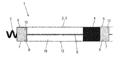
- FIG. 2 an enlarged view of the distal section of the electrode lead depicted in FIG. 1 .
- FIG. 3A-3B schematic depictions to illustrate an embodiment of the electrode lead assembly according to at least one embodiment of the invention.
- FIG. 4 a schematic depiction to illustrate an embodiment of the hydrogel sensor according to at least one embodiment of the invention.
- FIG. 5 a schematic depiction to illustrate a conventional, permanently implanted electrode lead.
- FIG. 6 a schematic depiction of a hydrogel capsule in combination with a water reservoir and a water-permeable connection/wall between the water reservoir and the hydrogel capsule.
- FIG. 5 shall be considered first; it shows a schematic depiction of an electrode lead 101 that is permanently implanted in a heart 105 and is well-known in the prior art.
- Electrode lead 101 is designed e.g. as a shock electrode lead in this case. It has a distal section 103 and a proximal end 102 which is connected to an implanted ICD 104 (implantable cardioverter/defibrillator). This is a device that can generate shock pulses e.g. to terminate a life-threatening ventricular fibrillation.
- Electrode lead 101 extends through right atrium 106 and is positioned via its distal section 103 inside right ventricle 107 .
- Distal section 103 is provided with a shock electrode 108 designed in the form of a helical wire, and which is in contact with the wall of ventricle 107 .
- the oblong helical shape of shock electrode 108 serves to enlarge the effective electrode surface.
- Distal section 103 furthermore includes a ring electrode 109 and a conical point electrode 110 , which can be used for purposes of palpation and/or stimulation (antibradycardia stimulation).
- a surface 111 of electrode lead 101 is electrically insulated except for electrodes 108 - 110 which are electrically conductive surface regions for transmitting electrical energy.
- electrode lead 1 is designed as an implantable pacemaker electrode lead, as an example. It can be implanted in a patient's body in a manner analogous to that illustrated in FIG. 5 , although a cardiac pacemaker (not depicted) instead of an ICD 104 will be connected to electrode lead 1 .
- FIG. 1 shows a distal section 2 of electrode lead 1 .
- electrode lead 1 has a tubular, flexible line body 5 that forms a line body cavity 19 .
- Line body 5 is provided with a point electrode 3 , which is designed in this case e.g. in the form of a screw-in electrode to be screwed into the cardiac tissue, and a proximally offset ring electrode 4 .
- Point electrode 3 and ring electrode 4 are connected to an electrical lead 6 (metallic core of the conductor) disposed inside line body cavity 19 ; electrical lead 6 can be connected at the proximal end of electrode lead 1 to the cardiac pacemaker.
- Point electrode 3 can be rotated by rotating electrical lead 6 in order to permanently anchor electrode lead 1 in the cardiac muscle tissue.
- the anchoring of an electrode lead using a screw-in electrode is known per se to a person skilled in the art e.g. from the aforementioned publication DE 20 2006 020 517 U1, and so it need not be discussed further here.
- Electrode lead 1 furthermore includes two hydrogel capsules 7 , one of which is thermally coupled to point electrode 3 , and the other of which is thermally coupled to ring electrode 4 .
- Hydrogel capsules 7 are directly adjacent to electrodes 3 , 4 , with which they are thermally coupled, and are in physical contact with each of them.
- Hydrogel capsules 7 are each accommodated in line body cavity 19 in entirety. Electrical lead 6 is fed through both hydrogel capsules 7 .
- Each hydrogel capsule 7 includes a wall 9 composed of an elastically resilient material; wall 9 forms a capsule cavity 8 which contains a hydrogel 10 .
- Hydrogel 10 is composed of a three-dimensional, hydrophilic polymer which, in the present embodiment, is e.g. poly(N-isopropylacrylamide) with poly-p-dioxanon as the hard segment.
- the swelling capacity of hydrogel 10 depends on temperature; the swelling capacity diminishes as the temperature increases.
- the swelling capacity of hydrogel 10 diminishes by at least 30% when temperature increases by 10° C.
- Walls 9 of hydrogel capsules 7 are so resilient that they can adapt to the volume of hydrogel 10 contained therein, the volume being dependent on the water content.
- walls 9 are made of a polyester having a suitable wall thickness; in the present embodiment, they can be composed of Parylene C having a large number of pinholes 11 .
- Pinholes 11 retain hydrogel 10 but allow water to pass through, thereby enabling the water content of hydrogel 10 to change depending on its temperature.
- Hydrogel capsules 7 each include a passage 12 to accommodate a guide wire (not depicted) for electrode lead 1 .
- Point electrode and ring electrode 3 , 4 are electrically conductive regions of an otherwise electrically insulated surface 13 of line body 5 , via which electrical energy can be transmitted from and to the surroundings. Walls 9 of hydrogel capsules 7 each form a part of surface 13 , thereby enabling water to freely enter and exit hydrogel 10 . Electrodes 3 , 4 are separated by a distance that is preferably in the range of 2 to 20 mm. Instead of a screw-in electrode, a point electrode 3 having a different shape could be used just as easily, e.g. a point electrode having a conical shape, as shown in FIG. 5 .
- the temperatures in point electrode 3 and/or ring electrode 4 can be monitored continually in electrode lead 1 .
- an outer dimension or size of the two hydrogel capsules such as a dimension in this case that is perpendicular to the extension direction of electrode lead 1 , via an evaluation of the nuclear resonance tomographic images.
- the temperature of point electrode and ring electrode 3 , 4 can be ascertained using a simple calibration measurement, in which a correlation between the size and temperature of hydrogel capsules 7 , 8 is determined.
- FIGS. 3A and 3B show an embodiment of electrode lead assembly according to the invention, which is labeled as a whole with reference numeral 14 .
- Electrode lead assembly 14 includes a conventional electrode lead which does not include hydrogel capsules and is labeled as a whole with reference numeral 1 ′.
- Electrode lead assembly 14 also includes a guide wire 15 for positioning electrode lead 1 ′.
- Electrode lead 1 ′ includes a tubular, flexible, electrically insulated line body 5 which is provided with a point electrode 3 , which is designed as a round cap, and a proximally offset ring electrode 4 , each of which are electrically conductive surface regions of line body 4 . Electrodes 3 , 4 are electrically connected to an electrical lead 6 disposed inside line body cavity 19 .
- Point electrode 3 is composed of a projecting cap section 16 and a plug-in section 17 integrally formed thereon, plug-in section 17 being inserted into the distal end of line body 5 and fixedly connected thereto. Plug-in section 17 forms an electrode cavity 18 that is open on one side.
- Guide wire 15 includes a hydrogel capsule 7 on its distal end, hydrogel capsule 7 being fixedly connected to guide wire 15 . Reference is made to the embodiments described above with regard for wall 9 and hydrogel 10 contained in hydrogel capsule 7 .
- hydrogel capsule 7 When guide wire 15 is inserted into line body cavity 19 and is brought into the working position in order to position electrode lead 1 ′, hydrogel capsule 7 enters electrode cavity 18 and is thermally coupled to point electrode 3 via physical contact (see FIG. 3A ). The temperature of point electrode 3 can therefore be monitored continually via a change in an outer dimension of hydrogel capsule 7 while electrode lead 1 ′ is being positioned. Guide wire 15 can then be removed, and hydrogel capsule 7 is drawn out of electrode cavity 18 (see FIG. 3B ). In a particularly advantageous manner, a conventional electrode lead 1 ′ can be used in this embodiment of the invention.
- FIG. 4 shows an embodiment of the implantable hydrogel sensor according to the invention, which is labeled as a whole with reference numeral 20 .
- hydrogel sensor 20 includes a hydrogel capsule 7 having a resilient wall 9 which forms a capsule cavity 8 containing a hydrogel 10 .
- Wall 9 is provided with a large number of pinholes 11 to allow water to pass from/to hydrogel 10 .
- Hydrogel sensor 22 can be implanted in order to detect the temperature of its surroundings via a measurement of an outer dimension or size of hydrogel capsule 7 . This takes place preferably via the evaluation of a nuclear resonance tomographic image.
- the temperature of implanted hydrogel sensor 20 increases by 4K, thereby resulting in a reduction in the volume of hydrogel capsule 7 due to water loss, which is clearly visible in the nuclear resonance tomographic image.
- FIG. 6 shows a hydrogel capsule in combination with a water reservoir.
- the electrode lead or the guide wire itself that is inserted therein contains a water reservoir 720 that is connected via a diaphragm 730 or duct to hydrogel capsule 710 , and so the water-permeable wall is formed, while the rest of the hydrogel capsule is water-impermeable.
- the water content can therefore move between the hydrogel capsule and water reservoir 740 , and the ratio of the water content can be evaluated accordingly using MRT image evaluation.
- This method offers the advantage that it can also be used in a component, such as the guide wire, that is insulated against the bodily fluid, and that no calibration or only very simple calibration is required to evaluate the ratio of the water content.
- At least one embodiment of the invention makes it possible, via the thermal coupling of electrodes to hydrogel capsules, to easily and reliably determine the temperature of the electrodes during a nuclear resonance tomographic examination, thereby making it possible to take nuclear resonance tomographic images even of patients who have an implanted electrode probe.
- Electrode leads and electrode lead assemblies according to the invention are characterized by a particularly simple use in practice and can be manufactured easily and cost effectively in high-volume production.
- At least one embodiment of the invention makes it possible to automatically control a nuclear resonance tomograph, wherein the intensity, for instance, of the electromagnetic alternating fields used for resonance excitation is reduced on the basis of the temperature of one or more electrodes of an implanted electrode lead, if the temperature of the electrode exceeds a predeterminable first threshold value.
- the electromagnetic alternating fields can be shut off entirely if the temperature of an electrode exceeds a predeterminable second temperature threshold value.
- the first and the second temperature threshold value can be the same or different.
- the temperature of one or more electrodes can be displayed in a graphical display device.
- An optical and/or acoustic warning signal can also be output as soon as the temperature of an electrode reaches a temperature threshold value of this type. It would also be feasible to specifically apply an electrical pulse to an electrode in order to ablate surrounding bodily tissue.
- the temperature of the electrode can be easily monitored and controlled via the thermally coupled hydrogel capsule.
Landscapes
- Health & Medical Sciences (AREA)
- Life Sciences & Earth Sciences (AREA)
- Public Health (AREA)
- Veterinary Medicine (AREA)
- Engineering & Computer Science (AREA)
- Biomedical Technology (AREA)
- Nuclear Medicine, Radiotherapy & Molecular Imaging (AREA)
- General Health & Medical Sciences (AREA)
- Animal Behavior & Ethology (AREA)
- Radiology & Medical Imaging (AREA)
- General Chemical & Material Sciences (AREA)
- Chemical & Material Sciences (AREA)
- Chemical Kinetics & Catalysis (AREA)
- Cardiology (AREA)
- Heart & Thoracic Surgery (AREA)
- Electrotherapy Devices (AREA)
Priority Applications (1)
| Application Number | Priority Date | Filing Date | Title |
|---|---|---|---|
| US13/191,347 US8565895B2 (en) | 2010-09-23 | 2011-07-26 | Implantable electrode lead and hydrogel sensor |
Applications Claiming Priority (2)
| Application Number | Priority Date | Filing Date | Title |
|---|---|---|---|
| US38556510P | 2010-09-23 | 2010-09-23 | |
| US13/191,347 US8565895B2 (en) | 2010-09-23 | 2011-07-26 | Implantable electrode lead and hydrogel sensor |
Publications (2)
| Publication Number | Publication Date |
|---|---|
| US20120078330A1 US20120078330A1 (en) | 2012-03-29 |
| US8565895B2 true US8565895B2 (en) | 2013-10-22 |
Family
ID=44534049
Family Applications (1)
| Application Number | Title | Priority Date | Filing Date |
|---|---|---|---|
| US13/191,347 Expired - Fee Related US8565895B2 (en) | 2010-09-23 | 2011-07-26 | Implantable electrode lead and hydrogel sensor |
Country Status (2)
| Country | Link |
|---|---|
| US (1) | US8565895B2 (de) |
| EP (1) | EP2436422A1 (de) |
Families Citing this family (5)
| Publication number | Priority date | Publication date | Assignee | Title |
|---|---|---|---|---|
| EP2545958B1 (de) * | 2011-07-12 | 2014-05-14 | Sorin CRM SAS | Sonde für implantierbare Herzprothese, die Schutzmittel gegen die Wärmeeffekte von Magnetresonanz-Feldern umfasst |
| WO2014081808A1 (en) * | 2012-11-20 | 2014-05-30 | Arizona Board Of Regents, A Body Corporate Of The State Of Arizona, Acting For And On Behalf Of Arizon State University | Responsive dynamic three-dimensional tactile display using hydrogel |
| CN108697887B (zh) * | 2016-02-26 | 2022-10-25 | 神经毫微股份公司 | 在软组织中提供植入点位的方法 |
| CN114007686A (zh) | 2019-01-04 | 2022-02-01 | 神经毫微股份公司 | 包括一个微电极或一组微电极的用于植入神经组织的探针 |
| WO2021086784A1 (en) * | 2019-10-28 | 2021-05-06 | Boston Scientific Neuromodulation Corporation | Systems and methods for measuring temperature on or near an implantable medical device |
Citations (8)
| Publication number | Priority date | Publication date | Assignee | Title |
|---|---|---|---|---|
| EP0306442A2 (de) | 1987-09-03 | 1989-03-08 | BIOTRONIK Mess- und Therapiegeräte GmbH & Co Ingenieurbüro Berlin | Implantierbare Elektrode zur Herzstimulation |
| US5869078A (en) * | 1996-04-25 | 1999-02-09 | Medtronic Inc. | Implantable variable permeability drug infusion techniques |
| DE19800697A1 (de) | 1998-01-10 | 1999-07-15 | Biotronik Mess & Therapieg | Einzel-Elektrodensonde, insbesondere für implantierbare Defibrillatoren |
| WO2004062714A1 (de) | 2003-01-13 | 2004-07-29 | Disetronic Licensing Ag | Automatische, von hydrogelen getriebene fördereinrichtung mit einstellbarer abgabecharakteristik zum fördern eines mediums, insbesondere insulin |
| DE102004061732A1 (de) | 2004-12-17 | 2006-07-06 | Technische Universität Dresden | Steuerbare Einrichtung aus mehreren Einzelspeicherzellen auf Hydrogelbasis |
| DE102005039040A1 (de) | 2005-08-18 | 2007-02-22 | Biotronik Crm Patent Ag | Implantierbare Elektrodenvorrichtung |
| DE202006020517U1 (de) | 2005-09-07 | 2008-10-09 | Biotronik Crm Patent Ag | Einschraubelektrodensonde zur kardiologischen Anwendung |
| EP2158840A2 (de) | 2008-08-27 | 2010-03-03 | BIOTRONIK CRM Patent AG | Implantierbarer Biosensor und Sensoranordnung |
-
2011
- 2011-07-26 US US13/191,347 patent/US8565895B2/en not_active Expired - Fee Related
- 2011-08-29 EP EP11179128A patent/EP2436422A1/de not_active Withdrawn
Patent Citations (8)
| Publication number | Priority date | Publication date | Assignee | Title |
|---|---|---|---|---|
| EP0306442A2 (de) | 1987-09-03 | 1989-03-08 | BIOTRONIK Mess- und Therapiegeräte GmbH & Co Ingenieurbüro Berlin | Implantierbare Elektrode zur Herzstimulation |
| US5869078A (en) * | 1996-04-25 | 1999-02-09 | Medtronic Inc. | Implantable variable permeability drug infusion techniques |
| DE19800697A1 (de) | 1998-01-10 | 1999-07-15 | Biotronik Mess & Therapieg | Einzel-Elektrodensonde, insbesondere für implantierbare Defibrillatoren |
| WO2004062714A1 (de) | 2003-01-13 | 2004-07-29 | Disetronic Licensing Ag | Automatische, von hydrogelen getriebene fördereinrichtung mit einstellbarer abgabecharakteristik zum fördern eines mediums, insbesondere insulin |
| DE102004061732A1 (de) | 2004-12-17 | 2006-07-06 | Technische Universität Dresden | Steuerbare Einrichtung aus mehreren Einzelspeicherzellen auf Hydrogelbasis |
| DE102005039040A1 (de) | 2005-08-18 | 2007-02-22 | Biotronik Crm Patent Ag | Implantierbare Elektrodenvorrichtung |
| DE202006020517U1 (de) | 2005-09-07 | 2008-10-09 | Biotronik Crm Patent Ag | Einschraubelektrodensonde zur kardiologischen Anwendung |
| EP2158840A2 (de) | 2008-08-27 | 2010-03-03 | BIOTRONIK CRM Patent AG | Implantierbarer Biosensor und Sensoranordnung |
Non-Patent Citations (1)
| Title |
|---|
| European Search Report dated Feb. 21, 2012, 8 pages. |
Also Published As
| Publication number | Publication date |
|---|---|
| EP2436422A1 (de) | 2012-04-04 |
| US20120078330A1 (en) | 2012-03-29 |
Similar Documents
| Publication | Publication Date | Title |
|---|---|---|
| JP5927176B2 (ja) | 神経組織と相互作用するためのデバイス、ならびにそれを作製および使用する方法 | |
| Kugel et al. | Hazardous situation in the MR bore: induction in ECG leads causes fire | |
| US8175679B2 (en) | Catheter electrode that can simultaneously emit electrical energy and facilitate visualization by magnetic resonance imaging | |
| ES2925367T3 (es) | Dispositivo de estimulación implantable activo para la estimulación de un nervio vago a demanda | |
| CN101511265B (zh) | 导管和医疗组件 | |
| CA2892996C (en) | Extracorporeal unit for inspecting the insulation of an electrical wire of an implanted medical device | |
| Stecco et al. | Patient safety issues in magnetic resonance imaging: state of the art | |
| JP4932914B2 (ja) | 誘導電流の測定システムおよび方法 | |
| US20120078330A1 (en) | Implantable electrode lead and hydrogel sensor | |
| CN104083823B (zh) | 一种mri兼容的植入式电极 | |
| JPH07265441A (ja) | 電極装置 | |
| JP2013505793A (ja) | Mriと併用可能なリードレス心臓ペースメーカー | |
| US20140249612A1 (en) | Mri compatible leads for a deep brain stimulation system | |
| Shellock et al. | Cardiac pacemakers and implantable cardioverter defibrillators: in vitro magnetic resonance imaging evaluation at 1.5-tesla | |
| Graesslin et al. | Detection of RF unsafe devices using a parallel transmission MR system | |
| Malik et al. | Injectable sensors based on passive rectification of volume-conducted currents | |
| Quirouet et al. | Sacral neuromodulation device heating during lumbar and pelvic magnetic resonance imaging—a phantom study | |
| Greatbatch et al. | Magnetic resonance safety testing of a newly‐developed fiber‐optic cardiac pacing lead | |
| US20110208075A1 (en) | System and Method for Guide Wire Detection | |
| CA2655515A1 (en) | Temperature sensing within a patient during mr imaging | |
| US8374705B2 (en) | Implantable medical lead with housing integrity indicator | |
| Bandorski et al. | Do endoscopy capsules interfere with implantable cardioverter-defibrillators? | |
| Carias et al. | The evaluation of steerable ultrasonic catheters for minimally invasive MRI‐guided cardiac ablation | |
| US20100217115A1 (en) | Temperature sensing within a patient during mr imaging | |
| Paralikar et al. | Feasibility and safety of longitudinal magnetic resonance imaging in a rodent model with intracortical microwire implants |
Legal Events
| Date | Code | Title | Description |
|---|---|---|---|
| AS | Assignment |
Owner name: BIOTRONIK SE & CO. KG, GERMANY Free format text: ASSIGNMENT OF ASSIGNORS INTEREST;ASSIGNOR:DOERR, THOMAS;REEL/FRAME:026652/0805 Effective date: 20110725 |
|
| STCF | Information on status: patent grant |
Free format text: PATENTED CASE |
|
| FPAY | Fee payment |
Year of fee payment: 4 |
|
| FEPP | Fee payment procedure |
Free format text: MAINTENANCE FEE REMINDER MAILED (ORIGINAL EVENT CODE: REM.); ENTITY STATUS OF PATENT OWNER: LARGE ENTITY |
|
| LAPS | Lapse for failure to pay maintenance fees |
Free format text: PATENT EXPIRED FOR FAILURE TO PAY MAINTENANCE FEES (ORIGINAL EVENT CODE: EXP.); ENTITY STATUS OF PATENT OWNER: LARGE ENTITY |
|
| STCH | Information on status: patent discontinuation |
Free format text: PATENT EXPIRED DUE TO NONPAYMENT OF MAINTENANCE FEES UNDER 37 CFR 1.362 |
|
| FP | Lapsed due to failure to pay maintenance fee |
Effective date: 20211022 |