US856492A - Railway-truck. - Google Patents
Railway-truck. Download PDFInfo
- Publication number
- US856492A US856492A US36085907A US1907360859A US856492A US 856492 A US856492 A US 856492A US 36085907 A US36085907 A US 36085907A US 1907360859 A US1907360859 A US 1907360859A US 856492 A US856492 A US 856492A
- Authority
- US
- United States
- Prior art keywords
- box
- truck
- journal
- railway
- side frame
- Prior art date
- Legal status (The legal status is an assumption and is not a legal conclusion. Google has not performed a legal analysis and makes no representation as to the accuracy of the status listed.)
- Expired - Lifetime
Links
Images
Classifications
-
- B—PERFORMING OPERATIONS; TRANSPORTING
- B61—RAILWAYS
- B61F—RAIL VEHICLE SUSPENSIONS, e.g. UNDERFRAMES, BOGIES OR ARRANGEMENTS OF WHEEL AXLES; RAIL VEHICLES FOR USE ON TRACKS OF DIFFERENT WIDTH; PREVENTING DERAILING OF RAIL VEHICLES; WHEEL GUARDS, OBSTRUCTION REMOVERS OR THE LIKE FOR RAIL VEHICLES
- B61F5/00—Constructional details of bogies; Connections between bogies and vehicle underframes; Arrangements or devices for adjusting or allowing self-adjustment of wheel axles or bogies when rounding curves
- B61F5/26—Mounting or securing axle-boxes in vehicle or bogie underframes
- B61F5/30—Axle-boxes mounted for movement under spring control in vehicle or bogie underframes
- B61F5/32—Guides, e.g. plates, for axle-boxes
Definitions
- This invention relates to certain new and useful improvements in railway trucks, the.
- e object of my invention is to simplify ,the construction of trucks so that the main parts, such as the bolster and axles with the wheels, can be qjliickly and easily taken out and replaced wit out taking down the whole truck as is necessary in the usual construction.
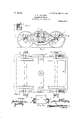
- Figure 1 represents a side view of a railway truck exemplifying my improve ments: Fig. 1-A,a detail of the key block and its su port.
- Fig. 2A a plan view of the truck.
- 2A an enlar ed detail showing the top of one end of a holster, the adjacent columns in section, and the key blocks in place.
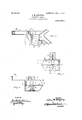
- Fig. 3 -a rear view of my journal box; and )art of side frame.
- Fig. 4 -an end view ol the upper ortion of the journal box cast with the side iiamc the lower ortion dashed to show its relation; and lg.
- a rcmov- I able key to form the connection with each, preferably by means of an opposing groove Ain the columns matching the column guides B on the truck bolster C, Fig. .Z-A; in the recess formed by those matching groov s, 1 place a loose rectangular block 1) that acts as a key.
- It is substantially as deep as the column guides on the bolster, which are about 5 inches, and is supported by a lip E that preferably forms part of the s rin ca l or other detachable piece.
- the lzey dfloc i may be simply supported on said lip E or may have arecess c, Fig.
- journal box of approved constuction, but divided so it will open and allow the axle to ass out on the wheels.
- This division is refiirably at the upper outer corner and at t e lower'inner corner ofthe door, formin two portions F and G res ectively,t ie one integral with the end 0% the side frame, and the other matching it and secured by pivot ins H and I, or otherwise, passing 1: iroug matchingflugs J J' and K K, as shown.
- the pins are rovided withcotters for ready removal. he stops L L on the inside of'the box for the journal brass to butt against, are thus p I the upper ortion of the box and the other- L on the ower ortion G. 'llVhen it is desired to open thehox, one pm I is withdrawn and the other pin H serves as a hinge on rection of the arrow, Fig. 1, acting to open the boxat the lines of division and thus to free the journal therein with its brass and wedge. It is only necessary to support the i end of the truck in order to run out the axle l and wheels.
- an end bar M preferably cast integrally with, or otherwise connecting the lower portions G of the journal boxes on the same axlev at each cud j and serving to connect the side frame.
- this bar M maybe fastened to extensions and side frame, and is smaller than the 0p-.
- box ortions G G are then separate and prefpivot pm I, and swlng downward as indicated by the arrow in Fig. 3.
- Butthis e'nd bar maybe dispensed with and other cross connections used, such as the "spring plank T, in the usual manner.
- the annular groove for the ;'dust guard is entirely closed at the top sides and bottom when the box is shut Flg. This is a better construction than the slot 1n the top of the box as in the ordinary form as the guard is protected around its whole edge from the entrance of dust, etc.
- the I- beamsection of the side frame is shown and the ln s J K 'are' preferably in line with the the upper portion F of the box.
- journal boxes are opened and thus set free the journals with their respecti've brass and wedge.
- a railway truck comprising side frames andjournal boxes,the latter being divided “and ,cast partly withsaid frames and part separately,and means to secure said divided boxes in matching position to said frames.
- Arailway truck comprising side frames and journal boxes,the latter being divided and the upper portion of eachbox being cast with said frame, and pivot fastenings to secure said divided boxes together, and allow about one pivot,-substantially as and for the.
- a railway truck comprising side frames I and journal boxes,the latter being divided diagonally and provided with hinge lugs,-
- a railway truck comprising side frames and journal boxes,the latter being divided and part of each tion in the plane bolts through said lugs securing said boxes in their matching position, and providing a hinge effect for opening the same.
- a railway truck comprising side frames having divided journal boxes,one portion F of each box comprising the top and part of the side with the brass stop Lbeing cast integral Wlth the frame, and the other portion.
- G comprising the brass stop L with side and bottom of the box being cast separately, and intermatching lugs JJ and KK, and pivot pins therefor, substantially as shown and'described.
- box being-integral withsai'd frame,intermatching lugs on each box porof the side frame, and pivot.
Description
PATENTED JUNE 11, 1907.
J. M. ROHLFING. RAILWAY TRUCK.
APPLICATION FILED MAR. a, 1907.
2 SHEETS-SHEET 1.
& iv? a h M mu m H N a nr k8 f w A 2 m r N0. 856,492. PATENTEDJUNB 11, 1907.
J. M. ROHLPING.
RAILWAY TRUCK.
APPLIOATIOK FILED MAR. e, 1907.
2 sums-sum z.
Afro/MEN JOHN MICHAEL nonnrme, on ST. LOUIS, MISSOURI.
RAILWAY-TRUCK- Specification of Letters Patent.
Patented June 11, 1907.
Application filed March 6, 1907. Serial No. 360.859.
To all whom it may concern:
Be it known that 1, JOHN MICHAEL Rom.- FING, a citizen of the United States, residing at St. Louis, in the State of Missouri, have invented certain new and useful Im rove ments in Railway-Trucks, of which t e following isa specification.
This invention relates to certain new and useful improvements in railway trucks, the.
eculiarities of which will be hereinafter described and claimed:
e object of my invention is to simplify ,the construction of trucks so that the main parts, such as the bolster and axles with the wheels, can be qjliickly and easily taken out and replaced wit out taking down the whole truck as is necessary in the usual construction.
To this end my improvements have reference to a divided journal box adapted to swing open to let out the wheels and axle; have reference to a combination of side frame and divided journal boxes, and to points of detail hereinafter claimed.
In the accompanyingdrawings on which like reference letters indicate corresponding parts. Figure 1,-represents a side view of a railway truck exemplifying my improve ments: Fig. 1-A,a detail of the key block and its su port. Fig. 2,a plan view of the truck. 2A,an enlar ed detail showing the top of one end of a holster, the adjacent columns in section, and the key blocks in place. Fig. 3,-a rear view of my journal box; and )art of side frame. Fig. 4,-an end view ol the upper ortion of the journal box cast with the side iiamc the lower ortion dashed to show its relation; and lg.
5,-a corresponding view of the matching lower portion of the journal box.
In the ordinary diamond frame. truck, when removing an axle and wheels, the bolts through the journal box and arch bars or the side frame, must be taken out before the axle.
can be run out of the frame: I show columns that are wider apart the.
the bolster at the guide lugs, and a rcmov- I able key to form the connection with each, preferably by means of an opposing groove Ain the columns matching the column guides B on the truck bolster C, Fig. .Z-A; in the recess formed by those matching groov s, 1 place a loose rectangular block 1) that acts as a key. It is substantially as deep as the column guides on the bolster, which are about 5 inches, and is supported by a lip E that preferably forms part of the s rin ca l or other detachable piece. The lzey dfloc i may be simply supported on said lip E or may have arecess c, Fig. 1-A, into which slide up and down with the bolster under the weight of the car, and thus prevent its jamming in the column groove, A. The key thus takes up the lateral thrust of the car on the bolster, and transmits it to the columns posin grooves by the amount of the required end lay, which-is usually one-quarter of an inch It is evident that the groove columns may be integral with the side frame or otherwise. It is not necessary, therefore, to provide a wider opening below the col- ;umns, but 0111 necessary to remove the block in the co umn grooves in order to remove the truck bolster. By taking out the support E the block readily slips down. I am aware this construction of key block and spring cap is old. At the ends of the side frame I rovide a journal box of approved constuction, but divided so it will open and allow the axle to ass out on the wheels. This division is refiirably at the upper outer corner and at t e lower'inner corner ofthe door, formin two portions F and G res ectively,t ie one integral with the end 0% the side frame, and the other matching it and secured by pivot ins H and I, or otherwise, passing 1: iroug matchingflugs J J' and K K, as shown.
The pins are rovided withcotters for ready removal. he stops L L on the inside of'the box for the journal brass to butt against, are thus p I the upper ortion of the box and the other- L on the ower ortion G. 'llVhen it is desired to open thehox, one pm I is withdrawn and the other pin H serves as a hinge on rection of the arrow, Fig. 1, acting to open the boxat the lines of division and thus to free the journal therein with its brass and wedge. It is only necessary to support the i end of the truck in order to run out the axle l and wheels.
I have shown in Figs. 1 and 2, an end bar M, preferably cast integrally with, or otherwise connecting the lower portions G of the journal boxes on the same axlev at each cud j and serving to connect the side frame. Instead of being integral with'the box portions l (l G, this bar M maybe fastened to extensions and side frame, and is smaller than the 0p-.
referahly located one on' the lip E enters, thereby causing the key to which to rotate the lower portion in the di- I 130 out when the erab y hinge on the m of the side frame as shown in Fig. 3. The
box ortions G G are then separate and prefpivot pm I, and swlng downward as indicated by the arrow in Fig. 3.
Butthis e'nd bar maybe dispensed with and other cross connections used, such as the "spring plank T, in the usual manner. In my construction, the annular groove for the ;'dust guard is entirely closed at the top sides and bottom when the box is shut Flg. This is a better construction than the slot 1n the top of the box as in the ordinary form as the guard is protected around its whole edge from the entrance of dust, etc. The I- beamsection of the side frame is shown and the ln s J K 'are' preferably in line with the the upper portion F of the box.
centra web. The stop P for the wedge used above the usual'journal brass is also cast on Thus the preferred construction provides -one brass stop L on the side frame and the matching where desirable, substantially as shown.
' merely dotted, at the left of Figs. 1 and 2, for
stop L on thehing'ed portion G of the box.
At the parting lines the lips Q and R, Figs. 3
and 5, assist in closing the joints. Stiffen-.
ing webs are provided for the lugs and box The end bar M and box portion G are shown.
the ,sake ofclearness and to indicate how readily the pair of Wheels and axle can be run I journal boxes are opened and thus set free the journals with their respecti've brass and wedge.
Having thus fully described my invention, whatl claim as new and desire to secure by Letters Patent, is: i
1. A railway truck comprising side frames andjournal boxes,the latter being divided "and ,cast partly withsaid frames and part separately,and means to secure said divided boxes in matching position to said frames.
2. Arailway truck comprising side frames and journal boxes,the latter being divided and the upper portion of eachbox being cast with said frame, and pivot fastenings to secure said divided boxes together, and allow about one pivot,-substantially as and for the.
cast
xes,-the latter being dividedeach 4. A railway truck comprising side frames I and journal boxes,the latter being divided diagonally and provided with hinge lugs,-
and pivotpins connecting said lugs in matching position, but allowing of opening said boxes, substantially as described.
5. A railway truck comprising side frames and journal boxes,the latter being divided and part of each tion in the plane bolts through said lugs securing said boxes in their matching position, and providing a hinge effect for opening the same.
6. A railway truck comprising side frames having divided journal boxes,one portion F of each box comprising the top and part of the side with the brass stop Lbeing cast integral Wlth the frame, and the other portion.
G comprising the brass stop L with side and bottom of the box being cast separately, and intermatching lugs JJ and KK, and pivot pins therefor, substantially as shown and'described.
" In testimony whereof I have afiixed my signature in presence of "twoWitnesses.
JOHN MICHAEL ROHLFING.
Witnesses:
E. P. WHELAN, WALTER N. DAVIS.
box being-integral withsai'd frame,intermatching lugs on each box porof the side frame, and pivot.
Priority Applications (1)
| Application Number | Priority Date | Filing Date | Title |
|---|---|---|---|
| US36085907A US856492A (en) | 1907-03-06 | 1907-03-06 | Railway-truck. |
Applications Claiming Priority (1)
| Application Number | Priority Date | Filing Date | Title |
|---|---|---|---|
| US36085907A US856492A (en) | 1907-03-06 | 1907-03-06 | Railway-truck. |
Publications (1)
| Publication Number | Publication Date |
|---|---|
| US856492A true US856492A (en) | 1907-06-11 |
Family
ID=2924947
Family Applications (1)
| Application Number | Title | Priority Date | Filing Date |
|---|---|---|---|
| US36085907A Expired - Lifetime US856492A (en) | 1907-03-06 | 1907-03-06 | Railway-truck. |
Country Status (1)
| Country | Link |
|---|---|
| US (1) | US856492A (en) |
-
1907
- 1907-03-06 US US36085907A patent/US856492A/en not_active Expired - Lifetime
Similar Documents
| Publication | Publication Date | Title |
|---|---|---|
| US895157A (en) | Car-truck. | |
| US1410516A (en) | Cab truck | |
| US856492A (en) | Railway-truck. | |
| US740617A (en) | Car-truck. | |
| US966376A (en) | Bolster-guide for truck-frames. | |
| US280087A (en) | schmelter | |
| US584489A (en) | Car-truck | |
| US969933A (en) | Journal-box. | |
| US670034A (en) | Dust-guard for journal-boxes. | |
| US991697A (en) | Car-truck. | |
| US944587A (en) | Car-truck. | |
| US943853A (en) | Car-truck. | |
| US1048874A (en) | Side-frame construction. | |
| US777726A (en) | Car-truck. | |
| US1084278A (en) | Car-truck side frame. | |
| US1068668A (en) | Truck side frame. | |
| US1336436A (en) | Railway-car | |
| US1007686A (en) | Car-truck. | |
| US1735239A (en) | Freight-car truck or tender truck | |
| US1131884A (en) | Car-truck. | |
| US809613A (en) | Railway-car. | |
| US598417A (en) | Thomas m | |
| US580534A (en) | richards | |
| US965600A (en) | Railway-car truck. | |
| US861766A (en) | Car-truck. |