US856434A - Shingling-gage for hatchets. - Google Patents
Shingling-gage for hatchets. Download PDFInfo
- Publication number
- US856434A US856434A US34417806A US1906344178A US856434A US 856434 A US856434 A US 856434A US 34417806 A US34417806 A US 34417806A US 1906344178 A US1906344178 A US 1906344178A US 856434 A US856434 A US 856434A
- Authority
- US
- United States
- Prior art keywords
- hatchet
- plate
- gage
- blade
- shingling
- Prior art date
- Legal status (The legal status is an assumption and is not a legal conclusion. Google has not performed a legal analysis and makes no representation as to the accuracy of the status listed.)
- Expired - Lifetime
Links
- 238000010276 construction Methods 0.000 description 2
- 229910011620 Lix My Inorganic materials 0.000 description 1
- 238000004519 manufacturing process Methods 0.000 description 1
- 230000001105 regulatory effect Effects 0.000 description 1
Images
Classifications
-
- B—PERFORMING OPERATIONS; TRANSPORTING
- B26—HAND CUTTING TOOLS; CUTTING; SEVERING
- B26B—HAND-HELD CUTTING TOOLS NOT OTHERWISE PROVIDED FOR
- B26B23/00—Axes; Hatchets
Definitions
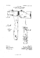
- Figure 1 is a side elevation of a shingling hatchet with theimprovement applied.
- Fig. 2 is a view of the eccentric ratchet wheel employed on the improved device.
- Fig. 3 is an end view of the device.
- 1 designates the handle provided with the usual blade 2 and driving head 3.
- gage plate 4 is a gage plate provided with gaging shoulders 5 and a bifurcated end 6 curving over the outer edge-of the blade 2.
- the plate 4 are a series of orifices 4, and 10 is a pin extending through the head of said hatchet and through 'one of said orifices 4, said pin 10 being slotted and having a key 16 in said slot for the purpose of regulating the position of the said pin and to keep it from turning by engaging with a groove in the hatchet.
- Encircling said pin 10 loosely is a ratchet wheel 11 provided with a rigid eccentric shoulder 12 extending into said orifice 4.
- Said ratchet wheel 11 engages with pins 13 which form a part of the plate 4, all for the purpose as will appear.
- Said ratchet wheel 11 is held on said pin 10 by means of a washer 14 and pin 15 extending through said pin 10.
- the plate 4 is arranged so that the distance between the end of the head 3 and the shoulders 5 will equal the length that is desired to have the shingles exposed.
- the nut 9 is then tightened and the shoulder 12- inserted in the orifice 4 and the washer 14 and the pin 15 inserted in position. This holds the plate 4 stationary in the desired position.
- the eccentric shoulder 1.2 thus causing the position of the plate 4 to be changed su'l'l'iciently to make up the loss oi distance occasioned by the wearing away of the head of said hatchet.
- the lugs 13 engaging the ratchet wheel 11 hold it in the desired position.
- a hatchet having an aperture through its body portion, of a gage plate bearing upon the outer end. of the hatchet body and provided with a plurality of spaced apertures near one end, and with a recess at the other end for bearing over they blade of the hatchet and with lateral shoulders adjacent to the recessed end, a clip device operating to adjustably connect the plate to the hatchet blade, a bolt operating through the aperture in the hatchet body and adapted to be consecutively engaged by the apertures in the blade, and means for adjustably securing said blade to said bolt.
- a gage plate bearing upon the outer end of the hatchet body and provided with a plurality of spaced apertures near one end and with a stop pin adjacent to each aperture and with a recess at the other end for hearing over the blade of the hatchet and with lateral shoulders adjacent to the recessed end, a clip device operating to adjustably connect the plate to the hatchet blade, a bolt operating through the aperture in the hatchet body and adapted to be consecutively engaged by the apertures in the blade, said bolt having a cam for operating in one of said gage plate apertures, and with a serrated disk adapted to be engaged by said stop pins, whereby the gage plate may be adjustably disposed longitudinally of the hatchet ocy.
- an attachment for shingling hatchets consisting of a gage plate adapted to bear upon the outer end of a hatchet body with. a recess at one end for hearing over the blade of the hatchet and with lateral shoulders adjacent to the recessed end and with a plurality of apertures near the other end, stop pins spaced from said apertures, an eccentric plate adapted to be rotatively disposed in one of said apertures and with a serrated. disk concentric with said eccentric plate and adapted to be engaged with said stop pins.
Landscapes
- Life Sciences & Earth Sciences (AREA)
- Forests & Forestry (AREA)
- Engineering & Computer Science (AREA)
- Mechanical Engineering (AREA)
- Details Of Spanners, Wrenches, And Screw Drivers And Accessories (AREA)
Description
No. 856,434. PATBNTED JUNE 11, 1907.
' O. VOLLMER. SHINGLING GAGBFOR HATGHETS.
APPLICATION FILED NOV.19, 1906.
CHARLES voLIiMER, or DUNriieAN, CALIFORNIA.
SHINGLlNG-GAGE FOR HATCHETS.
Specification of Letters Patent.
Patented June 11, 1907.
Application filed November 19,1906. Serial No. 344,178.
To a whom it may concern.-
Be it known that I, CHARLEs VOLLMER, a
citizen of the United States, and a resident in attachments for shingling hatchets for the purpose of gaging the length of the shingles to be exposed to the weather, my object being to produce a gage which may be accurately and effectively used for the purpose for which it is designed; also one which may be quickly and easily adjusted to accurately denote the length desired. These objects I obtain by means of a gage blade adjustably arranged on the top of the shingling hatchet, and by such other and further construction as will appear by a perusal of the following specifications and claims.
In the drawings similar characters 01" reference indicate corresponding parts in the several views.
Figure 1 is a side elevation of a shingling hatchet with theimprovement applied. Fig. 2 is a view of the eccentric ratchet wheel employed on the improved device. Fig. 3 is an end view of the device.
1 designates the handle provided with the usual blade 2 and driving head 3.
4 is a gage plate provided with gaging shoulders 5 and a bifurcated end 6 curving over the outer edge-of the blade 2.
7 is a rod provided on its lower end with a hook 8 gripping the inner edge of the blade 2,
the up er end of said rod being threaded and extent ing through the plate 4 and having a nut 9 mounted on said threaded portion. the plate 4 are a series of orifices 4, and 10 is a pin extending through the head of said hatchet and through 'one of said orifices 4, said pin 10 being slotted and having a key 16 in said slot for the purpose of regulating the position of the said pin and to keep it from turning by engaging with a groove in the hatchet. Encircling said pin 10 loosely is a ratchet wheel 11 provided with a rigid eccentric shoulder 12 extending into said orifice 4. Said ratchet wheel 11 engages with pins 13 which form a part of the plate 4, all for the purpose as will appear. Said ratchet wheel 11 is held on said pin 10 by means of a washer 14 and pin 15 extending through said pin 10.
In using the device the plate 4 is arranged so that the distance between the end of the head 3 and the shoulders 5 will equal the length that is desired to have the shingles exposed. The nut 9 is then tightened and the shoulder 12- inserted in the orifice 4 and the washer 14 and the pin 15 inserted in position. This holds the plate 4 stationary in the desired position. As the end of the head 3 wears down the ratchet wheel 11 may be rotated, the eccentric shoulder 1.2 thus causing the position of the plate 4 to be changed su'l'l'iciently to make up the loss oi distance occasioned by the wearing away of the head of said hatchet. The lugs 13 engaging the ratchet wheel 11 hold it in the desired position. By providing a plurality of apertures 4, and the stop lugs 13, dif'l'erent lengths of shingles may be gaged as will be obvious. Thus it will be seen that I have provided a shingle gage 'l'or shingle hatchcts which may be easily adjusted to meet all contingencies; also one which, though simple in construction, is very el'l'ective for the purpose for which it is designed.
.I/Vhile the above is a detailed description 01'" the present andpre'l erred embodiment of my invention, yet in practice many small changes in said details may be resorted to without departing from the spirit of my invention.
Having thus described my invention what I claim as new and useful and desire to secure by Letters Patent is 1. The combination with a hatchet having an aperture through its head portion, of a gage device comprising a plate bearing upon the outer end of the hatchet body and. with a recess at one end bearing over the hatchet blade and with lateral shoulders extending beyond the recessed end ofthe same, a clamping device operating to hold the plate upon the blade portion of the hatchet, a bolt operating through the aperture in the hatchet body, and with an eccentric thereon operating in a cavity in the blade, a serrated disk carried by said eccentric and adapted to engage a pin extending from said plate, whereby the plate may be adjusted longitudinally of the hatchet body.
ICC
2. The combination with a hatchet having an aperture through its body portion, of a gage plate bearing upon the outer end. of the hatchet body and provided with a plurality of spaced apertures near one end, and with a recess at the other end for bearing over they blade of the hatchet and with lateral shoulders adjacent to the recessed end, a clip device operating to adjustably connect the plate to the hatchet blade, a bolt operating through the aperture in the hatchet body and adapted to be consecutively engaged by the apertures in the blade, and means for adjustably securing said blade to said bolt.
The combination with a hatchet having an aperture through its body portion, of a gage plate bearing upon the outer end of the hatchet body and provided with a plurality of spaced apertures near one end and with a stop pin adjacent to each aperture and with a recess at the other end for hearing over the blade of the hatchet and with lateral shoulders adjacent to the recessed end, a clip device operating to adjustably connect the plate to the hatchet blade, a bolt operating through the aperture in the hatchet body and adapted to be consecutively engaged by the apertures in the blade, said bolt having a cam for operating in one of said gage plate apertures, and with a serrated disk adapted to be engaged by said stop pins, whereby the gage plate may be adjustably disposed longitudinally of the hatchet ocy.
4. As a new article of manufacture, an attachment for shingling hatchets consisting of a gage plate adapted to bear upon the outer end of a hatchet body with. a recess at one end for hearing over the blade of the hatchet and with lateral shoulders adjacent to the recessed end and with a plurality of apertures near the other end, stop pins spaced from said apertures, an eccentric plate adapted to be rotatively disposed in one of said apertures and with a serrated. disk concentric with said eccentric plate and adapted to be engaged with said stop pins.
In testimony whereof I al'liX my signature in presence of two witnesses.
CHARLES VOLLMER.
Witnesses:
H. H. GABLE, JOE KERR.
Priority Applications (1)
| Application Number | Priority Date | Filing Date | Title |
|---|---|---|---|
| US34417806A US856434A (en) | 1906-11-19 | 1906-11-19 | Shingling-gage for hatchets. |
Applications Claiming Priority (1)
| Application Number | Priority Date | Filing Date | Title |
|---|---|---|---|
| US34417806A US856434A (en) | 1906-11-19 | 1906-11-19 | Shingling-gage for hatchets. |
Publications (1)
| Publication Number | Publication Date |
|---|---|
| US856434A true US856434A (en) | 1907-06-11 |
Family
ID=2924889
Family Applications (1)
| Application Number | Title | Priority Date | Filing Date |
|---|---|---|---|
| US34417806A Expired - Lifetime US856434A (en) | 1906-11-19 | 1906-11-19 | Shingling-gage for hatchets. |
Country Status (1)
| Country | Link |
|---|---|
| US (1) | US856434A (en) |
-
1906
- 1906-11-19 US US34417806A patent/US856434A/en not_active Expired - Lifetime
Similar Documents
| Publication | Publication Date | Title |
|---|---|---|
| US856434A (en) | Shingling-gage for hatchets. | |
| US643539A (en) | Shears. | |
| US1387316A (en) | Combination-tool | |
| US464075A (en) | Combined scissors | |
| US1294553A (en) | Saw-handle. | |
| US1603223A (en) | Gripper bar for printing presses | |
| US324803A (en) | Island | |
| US946163A (en) | Saw-handle. | |
| US951324A (en) | Tool-head clamp. | |
| US191463A (en) | Improvement in awl-handles | |
| US1727158A (en) | Undercutter | |
| US936152A (en) | Shingling-gage. | |
| US522688A (en) | Sh ing ling-hatchet | |
| US287027A (en) | Heney iwan and louis iwls | |
| US1266081A (en) | Bolt-fastener or lock. | |
| US497517A (en) | Lathe-dog | |
| US539474A (en) | William l | |
| US1760648A (en) | Scraper-blade attachment for brooms | |
| US547540A (en) | Try and bevel square | |
| US628483A (en) | Shears. | |
| US1198089A (en) | Ax. | |
| US1051190A (en) | Woodworking-tool. | |
| US853198A (en) | Shingling-gage attachment for hatchets. | |
| US589626A (en) | Scissors-sharpener | |
| US213257A (en) | Improvement in spoke-shaves |