US856427A - Flexible metallic hose. - Google Patents
Flexible metallic hose. Download PDFInfo
- Publication number
- US856427A US856427A US34308806A US1906343088A US856427A US 856427 A US856427 A US 856427A US 34308806 A US34308806 A US 34308806A US 1906343088 A US1906343088 A US 1906343088A US 856427 A US856427 A US 856427A
- Authority
- US
- United States
- Prior art keywords
- members
- lever
- bolt
- flexible metallic
- metallic hose
- Prior art date
- Legal status (The legal status is an assumption and is not a legal conclusion. Google has not performed a legal analysis and makes no representation as to the accuracy of the status listed.)
- Expired - Lifetime
Links
Images
Classifications
-
- F—MECHANICAL ENGINEERING; LIGHTING; HEATING; WEAPONS; BLASTING
- F16—ENGINEERING ELEMENTS AND UNITS; GENERAL MEASURES FOR PRODUCING AND MAINTAINING EFFECTIVE FUNCTIONING OF MACHINES OR INSTALLATIONS; THERMAL INSULATION IN GENERAL
- F16L—PIPES; JOINTS OR FITTINGS FOR PIPES; SUPPORTS FOR PIPES, CABLES OR PROTECTIVE TUBING; MEANS FOR THERMAL INSULATION IN GENERAL
- F16L37/00—Couplings of the quick-acting type
- F16L37/24—Couplings of the quick-acting type in which the connection is made by inserting one member axially into the other and rotating it to a limited extent, e.g. with bayonet action
- F16L37/256—Couplings of the quick-acting type in which the connection is made by inserting one member axially into the other and rotating it to a limited extent, e.g. with bayonet action the coupling not being coaxial with the pipe
Definitions
- SHEETS-SHEET 1 affozum a No. 856.427. PATENTED JUNE. 11, 1907.
- This invention relates to a flexible metallic hose.
- the object of the invent ion is to produce a llexibhmetallic hose for air. steam, or other purposts to be used instead of rubber hose, bet-ween ears and other places where flexibility and hnlestruetibility are necessary.
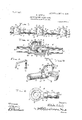
- Figure 1 ol the accompanying drawings represents a side elevntiotroi a portion of a hose constructed in accordance with this invention
- Fig. 2 represents a longitudinal section through one of the links or sections
- Fig. 3 represents a perspective view of the screw bolt and operating lever connected. therewith
- Fig. 4 represents a perspective view of the member having a bolt carrying bracket mounted thereon with the lever in slightly open position
- Fig. represents a top plan view oi the other link m mber
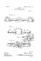
- Fig. 6 represents a sideelevntion oi a slightly modified form of the invention
- Fig. 7 rep resents a side elevation of another modification
- Fig. 8 represents a longitudinal section of the modification shown in Fig. 7
- Fig. 9 represents a longitudinal section oi another modification of the invention.
- a flexible metallic hose or pipe is formed of a plurality of connected members 10 and 20.
- the member 10 consists of a bowl-shaped or hollow hemispherical portion 11 having an annular upwardly pro ecting flange or nb 12 spaced from the inner edge of the opening therein to provide a gasket seat 13.
- This portion 11 has a socket 14 in its outer face in the crest thereof to receive a clamping screw bolt hereinafter described.
- a tubularportion or pipe 15 extends from one sideof the hollow portion 11 anti is offset at 16 and extended laterally at 17'; with said lateral extenion 17 screw-threaded exteriorly for connection to-a similar section or link by acoupsl'eeve 50.
- a reinforcing shoulder 16 is formed on the pipe 15
- a gasket 18 of rubher, lead, or other suitable material is disposed in the seat 13 and projects'slightly beyondthe flange 12.
- the link member 20 comprises a hollow hemispherical portion 21 of the same general construction as the part 11 of the member 10 except that its flat face has a depression 22 surrounding the edge of its opening to form aseat for the flange and gasket of the member 10.
- a pipe 23 leads from one side of this rounded member 10 and is offset and enlarged to form a lateral extension 24 which is also exteriorly screw-threaded for connection with the adjacent hose section.
- a reinforcing shoulder 21 is formed at the onset portion of the pipe. 31.
- a standard 25 is mounted on. the member 20 preferably on the shoulder 24 thereof and provided with a lateral arm 26 having a recess 27 in itsouter lace and a transverse screw-threaded opening 28 in its free end.
- a spring '29 is attached to said. arm, preferably at its junction with the standard, and a ring 30 is slidabiy disposed on said standard for a purpose soon to be described.
- a screw-threaded bolt 31 extends through the opening 28 in the end of the arm 26 and has a rounded head 32 on one end and a lever 3 is pivoted to the other end thereof, the head 32 being adapted to turn in the socket 14 of the member 10 to lock the members 10 and 20 mo'vably together, a ball and socket j oint'being formed thereby.
- This lever 33 is preferably bifurcated at the end which is connected to the bolt 31 and is adapted to swing from the top of said screw-bolt.
- the free end of this lever 33 is preferably bent to fit the angle at the junction of the arm and standard and has a notch 34 with which the ring 30 is engaged and in conjunction with the spring 29 holds said lever in closed position.
- the round-part 11 o the member 10 is placed over the part 21' of the member 20 with the gasket 18 arranged between them.
- the lever 33 is then swung over with its bent end extended in position to serve as a handle for turning the bolt.
- the lever is turned untilthe head 32 of the bolt 31 fits in the socket 14 and secures the members together.
- the lever 33 is then swung over into the. recess or groove 27 with the wall face'of its bent end bearing on the spring 29, the ring; is slid over said end into the notch 34 and the parts are plurality comiecteo. sccti sect on com;
- a piurality section co ble met-ailic h composed of a one mema gasket lisioces of said I members, a screW-bolt,engaging onepi said members, a lever pivotally connected with said screw-bolt, and a link for engaging saidlever to lock said members together.
- a flexible metallic hose composed of a plurality of connected sections or links, each section comprising two members, one member having an annular recess therein and the other member having an annular project on to fit in said recess, a-gaskct disposed between the meeting faces of said members, a
- a flexible metallic hose composed of a plurality of connected sections or links, each section comprising two members, one memberhaving an annular recess thereinand the other member having an annular projection to fit in said recess,a gasket disposed.
- a bracket disposed on one 01' said members and extending over the other member, a screwbolt mounted in said bracket and engaging one of said members, a lever pivoted to said screw-bolt, sald bracket having a recess to receive said lever, and a link carried by said bracket adapted to engage said lever.
- a flexible metallic nose composed of a plurality of connected sections or links, each section comprising two members, one member havingan annular recess therein and the other member having an annular pro ection to fit in said recess,a gasket disposed be' tween the meeting faces of said members, a bracket disposed on one of said members and extending over the other member, a screwi H i'g .m;,, c 7. bolt mounted in said bracket and engaging one of said members, lever pivoted to said screw bolt, said bracket having a recess to receive said lever, a spring in said recess, and a link on said bracket to engage said lever.
Description
PATENTED JUNE 11 I NoQ856A2'7.
W. SOHULZ. FLEXIBLE METALLIC HOSE.
APPLICATION FILED NOV. 12, 1906.
2 SHEETS-SHEET 1 affozum a No. 856.427. PATENTED JUNE. 11, 1907.
W. SOHULZ.
FLEXIBLE METALLIC HOSE.
APPLICATION FILED NOV. 12, 1906.
'2 SHEBTS-SHEET 2 WW I moses \YILIHCLM sonunz, or HOUSTON, TEXAS.
FLEXIBLE METALLIC HOSE.
Specification of Letters Patent.
Patented June 11,1907.
Application tiled November 12,1906. Serial No- 343,088.
To rt/l whom it mu, cmmcrn.
Be it known that I, WILIIELM SonULz, a
citizen of the United States, residing at Houston, in the county of llarris and State of Texas, have invented certain new and useful Improvements in a Flexible Metallic Hose; and I do declare the following to be a full, clear, and exact deseription of the invention, such as will enable others skilled in the art to which it appertains to make and use the same.
This invention relates to a flexible metallic hose.
The object of the invent ion is to produce a llexibhmetallic hose for air. steam, or other purposts to be used instead of rubber hose, bet-ween ears and other places where flexibility and hnlestruetibility are necessary.
Figure 1 ol the accompanying drawings represents a side elevntiotroi a portion of a hose constructed in accordance with this invention; Fig. 2 represents a longitudinal section through one of the links or sections; Fig. 3 represents a perspective view of the screw bolt and operating lever connected. therewith; Fig. 4 represents a perspective view of the member having a bolt carrying bracket mounted thereon with the lever in slightly open position; Fig. represents a top plan view oi the other link m mber: Fig. 6 represents a sideelevntion oi a slightly modified form of the invention; Fig. 7 rep resents a side elevation of another modification; Fig. 8 represents a longitudinal section of the modification shown in Fig. 7 and Fig. 9 represents a longitudinal section oi another modification of the invention.
In the embodiment shown in Figs. 1 to 5, a flexible metallic hose or pipe is formed of a plurality of connected members 10 and 20. The member 10 consists of a bowl-shaped or hollow hemispherical portion 11 having an annular upwardly pro ecting flange or nb 12 spaced from the inner edge of the opening therein to provide a gasket seat 13. This portion 11 has a socket 14 in its outer face in the crest thereof to receive a clamping screw bolt hereinafter described. A tubularportion or pipe 15 extends from one sideof the hollow portion 11 anti is offset at 16 and extended laterally at 17'; with said lateral extenion 17 screw-threaded exteriorly for connection to-a similar section or link by acoupsl'eeve 50. A reinforcing shoulder 16 is formed on the pipe 15 A gasket 18 of rubher, lead, or other suitable material is disposed in the seat 13 and projects'slightly beyondthe flange 12.
- The link member 20 comprises a hollow hemispherical portion 21 of the same general construction as the part 11 of the member 10 except that its flat face has a depression 22 surrounding the edge of its opening to form aseat for the flange and gasket of the member 10. A pipe 23 leads from one side of this rounded member 10 and is offset and enlarged to form a lateral extension 24 which is also exteriorly screw-threaded for connection with the adjacent hose section. A reinforcing shoulder 21 is formed at the onset portion of the pipe. 31. A standard 25 is mounted on. the member 20 preferably on the shoulder 24 thereof and provided with a lateral arm 26 having a recess 27 in itsouter lace and a transverse screw-threaded opening 28 in its free end. A spring '29 is attached to said. arm, preferably at its junction with the standard, and a ring 30 is slidabiy disposed on said standard for a purpose soon to be described.
A screw-threaded bolt 31 extends through the opening 28 in the end of the arm 26 and has a rounded head 32 on one end and a lever 3 is pivoted to the other end thereof, the head 32 being adapted to turn in the socket 14 of the member 10 to lock the members 10 and 20 mo'vably together, a ball and socket j oint'being formed thereby. This lever 33 is preferably bifurcated at the end which is connected to the bolt 31 and is adapted to swing from the top of said screw-bolt. The free end of this lever 33 is preferably bent to fit the angle at the junction of the arm and standard and has a notch 34 with which the ring 30 is engaged and in conjunction with the spring 29 holds said lever in closed position.
To assemble the )arts of this hose section, the round-part 11 o the member 10 is placed over the part 21' of the member 20 with the gasket 18 arranged between them. The lever 33 is then swung over with its bent end extended in position to serve as a handle for turning the bolt. The lever is turned untilthe head 32 of the bolt 31 fits in the socket 14 and secures the members together. The lever 33 is then swung over into the. recess or groove 27 with the wall face'of its bent end bearing on the spring 29, the ring; is slid over said end into the notch 34 and the parts are plurality comiecteo. sccti sect on com;
in the form s a heL-"nlspl o osite ends, being disposed portion th in the iii members 10 r 7 sad 8, the are similar to thend 2% except the brackets formed on he standard and are disperised with, a connecting scre z bolt 31 is extended ti i lar to th Lat two brackets l hose scr .v-bcitii are shown, one on II J ,m'l 1i} em; 26 I claim as mv iiiventiciiz- 1. A; flexible metal s v irks, each one mem- U two In Jeers, v m M H L be; having an annular recess in the other member hav S, it
3. A flexible metallic hose composed of a plurality of connected sections or links, each section comprising two members, one member having an annular recess therein and the other member having an annular project on to fit in said recess, a-gaskct disposed between the meeting faces of said members, a
-,-bracket disposed on one of said members and extending over the other member, a screwbolt. mounted in said bracket and engaging one or said members, a lever-pivoted to said screw bolt, and a link carried by said bracket and adapted to engage said, lever to lock the members together.
4. A flexible metallic hose composed of a plurality of connected sections or links, each section comprising two members, one memberhaving an annular recess thereinand the other member having an annular projection to fit in said recess,a gasket disposed. be-
tween the meeting faces of said members, a bracket disposed on one 01' said members and extending over the other member, a screwbolt mounted in said bracket and engaging one of said members, a lever pivoted to said screw-bolt, sald bracket having a recess to receive said lever, and a link carried by said bracket adapted to engage said lever.
5. A flexible metallic nose composed of a plurality of connected sections or links, each section comprising two members, one member havingan annular recess therein and the other member having an annular pro ection to fit in said recess,a gasket disposed be' tween the meeting faces of said members, a bracket disposed on one of said members and extending over the other member, a screwi H i'g .m;,, c 7. bolt mounted in said bracket and engaging one of said members, lever pivoted to said screw bolt, said bracket having a recess to receive said lever, a spring in said recess, and a link on said bracket to engage said lever.
In tcstimon T whereof I have hereunto set my hand in presence oi two subscribing wit- QESSGS. i
WiLHELl/i SCl-IULZ. Witnesses:
A. Hv Kirss'rss, WM. Kmas'rss.
Priority Applications (1)
| Application Number | Priority Date | Filing Date | Title |
|---|---|---|---|
| US34308806A US856427A (en) | 1906-11-12 | 1906-11-12 | Flexible metallic hose. |
Applications Claiming Priority (1)
| Application Number | Priority Date | Filing Date | Title |
|---|---|---|---|
| US34308806A US856427A (en) | 1906-11-12 | 1906-11-12 | Flexible metallic hose. |
Publications (1)
| Publication Number | Publication Date |
|---|---|
| US856427A true US856427A (en) | 1907-06-11 |
Family
ID=2924882
Family Applications (1)
| Application Number | Title | Priority Date | Filing Date |
|---|---|---|---|
| US34308806A Expired - Lifetime US856427A (en) | 1906-11-12 | 1906-11-12 | Flexible metallic hose. |
Country Status (1)
| Country | Link |
|---|---|
| US (1) | US856427A (en) |
Cited By (4)
| Publication number | Priority date | Publication date | Assignee | Title |
|---|---|---|---|---|
| US2845091A (en) * | 1954-01-18 | 1958-07-29 | Maryland Engineering Company | Tank cleaning apparatus |
| KR100766811B1 (en) * | 2006-12-26 | 2007-10-17 | 동방중전기(주) | The soundproof wall for prefabricated panel |
| US20090242671A1 (en) * | 2008-03-25 | 2009-10-01 | Erickson Perry D | Articulating faucet and joint therefor |
| US9568132B2 (en) | 2012-07-13 | 2017-02-14 | Kohler Co. | Clutched joint for articulating faucet |
-
1906
- 1906-11-12 US US34308806A patent/US856427A/en not_active Expired - Lifetime
Cited By (6)
| Publication number | Priority date | Publication date | Assignee | Title |
|---|---|---|---|---|
| US2845091A (en) * | 1954-01-18 | 1958-07-29 | Maryland Engineering Company | Tank cleaning apparatus |
| KR100766811B1 (en) * | 2006-12-26 | 2007-10-17 | 동방중전기(주) | The soundproof wall for prefabricated panel |
| US20090242671A1 (en) * | 2008-03-25 | 2009-10-01 | Erickson Perry D | Articulating faucet and joint therefor |
| US8070076B2 (en) | 2008-03-25 | 2011-12-06 | Kohler Co. | Articulating faucet and joint therefor |
| US9568132B2 (en) | 2012-07-13 | 2017-02-14 | Kohler Co. | Clutched joint for articulating faucet |
| US10495243B2 (en) | 2012-07-13 | 2019-12-03 | Kohler Co. | Clutched joint for articulating faucet |
Similar Documents
| Publication | Publication Date | Title |
|---|---|---|
| US489107A (en) | Carl august guido storz | |
| US856427A (en) | Flexible metallic hose. | |
| US545066A (en) | Hose-coupling | |
| US817785A (en) | Joint for artificial limbs. | |
| US955979A (en) | Hot-water-radiator valve. | |
| US505703A (en) | Packing-gasket | |
| US1220270A (en) | Flexible pipe-joint. | |
| US762777A (en) | Hose or pipe coupling. | |
| US931810A (en) | Automatic sash and transom center. | |
| US383360A (en) | Hose-coupling | |
| US656667A (en) | Flexible metal pipe-coupling. | |
| US794979A (en) | Swivel-hook. | |
| US961552A (en) | Lock for swing-joints. | |
| US227943A (en) | Peters | |
| US1519095A (en) | Quick-acting pump coupling | |
| US409512A (en) | Hose-coupling | |
| US925880A (en) | Gate-valve. | |
| US724324A (en) | Hose-coupling. | |
| US999564A (en) | Flexible pipe. | |
| US910687A (en) | Flexible pipe-joint. | |
| US954348A (en) | Hose-coupling. | |
| US613600A (en) | Joseph plant | |
| US870763A (en) | Hose-band. | |
| US1100416A (en) | Ball-joint. | |
| US842555A (en) | Miter-clamp. |