US856422A - Gear-case. - Google Patents
Gear-case. Download PDFInfo
- Publication number
- US856422A US856422A US26349505A US1905263495A US856422A US 856422 A US856422 A US 856422A US 26349505 A US26349505 A US 26349505A US 1905263495 A US1905263495 A US 1905263495A US 856422 A US856422 A US 856422A
- Authority
- US
- United States
- Prior art keywords
- plates
- gear
- thin
- riveted
- edges
- Prior art date
- Legal status (The legal status is an assumption and is not a legal conclusion. Google has not performed a legal analysis and makes no representation as to the accuracy of the status listed.)
- Expired - Lifetime
Links
Images
Classifications
-
- F—MECHANICAL ENGINEERING; LIGHTING; HEATING; WEAPONS; BLASTING
- F16—ENGINEERING ELEMENTS AND UNITS; GENERAL MEASURES FOR PRODUCING AND MAINTAINING EFFECTIVE FUNCTIONING OF MACHINES OR INSTALLATIONS; THERMAL INSULATION IN GENERAL
- F16P—SAFETY DEVICES IN GENERAL; SAFETY DEVICES FOR PRESSES
- F16P1/00—Safety devices independent of the control and operation of any machine
- F16P1/02—Fixed screens or hoods
-
- Y—GENERAL TAGGING OF NEW TECHNOLOGICAL DEVELOPMENTS; GENERAL TAGGING OF CROSS-SECTIONAL TECHNOLOGIES SPANNING OVER SEVERAL SECTIONS OF THE IPC; TECHNICAL SUBJECTS COVERED BY FORMER USPC CROSS-REFERENCE ART COLLECTIONS [XRACs] AND DIGESTS
- Y10—TECHNICAL SUBJECTS COVERED BY FORMER USPC
- Y10T—TECHNICAL SUBJECTS COVERED BY FORMER US CLASSIFICATION
- Y10T74/00—Machine element or mechanism
- Y10T74/21—Elements
- Y10T74/219—Guards
- Y10T74/2191—Guards for rotary member
Definitions
- the drawings My invention relates to fear eases enibut as the armature sljud't does not' ⁇ pri'ijeet ployed lor iuelosinej and protecting the Agear through this side of the gear ease, the blanks 1o' ⁇ Wheels and pinions used for tmnsniittinf;l are provided with only 'the soun-eu'eular repower at reduced speeds from railwa)Y motor eesses i2 and '13 for the truek axle (i.
- ⁇ the vehicles blank 3 is provided with upwardly projecting in eonneetion with which thei ⁇ are used.
- the blank ll is similarly provided with pensive in eonstruetion, light in weight and lips 18 and 10 adjacent toits ends and lips 7o durable in serviee. 2() and 2l. adjacent to its reeess l.
- the llecetofore it ⁇ has been the usual praetiee to blank 2 is provided with a transverse out 22 Construct railwa motor gear eases ol ⁇ inallethat extends inward for a considerable dis- 2o able iron castings thougrh ii has been also tancel from its lower edge adjaeent to one proposed to minul'aotiue them oi pressed end and a similar eut 23 adjacent lo its other 75 steek The malleable iron castings whieh end.
- the blank 1l is similari)v provided havefbeen usuali)V employed have been ot' unwith ents 24 and 25 adjacent 'to its respective desirable weight: and liable to breakage in ends.
- Fig. 1 is an end elevation 27 are bent over the edges ol' the plates 2 85 ol a portion of the gear ease slmwn .
- Fig. 1. and 3 as indicated at 30 and 31 and are Fig. 3 is a side elevation ol one ol' the upper riveted thereto.
- the adjaeent edges of the blanks used in making ⁇ the rear ease. li'ipzfi plates 2S and are bent or iolded over tl'e 35 is a side elevation oi the other upper blank.
- :'i is a side elevation ot' the lower blank as indicated at 32 and 33% and are riviped 9o l'o.- the saine side as the upper blank shown thereto
- the plates 26 and 27 and 28 and in File; 4, and Fig'. t3 is. a side elevation of the 29 are also securely riveted to the eorrelower blank lor the same side as the. blank spending' plates 2 and 3 and it) and l1 alongA 4o slio. ⁇ 'n'i11lt ⁇ i ⁇ .. 5. their respective upper and lower edges, at
- the gear 'ase 1 which is eonstrueted in aetheir ends and around the openiings l'ornied 95 eor'dunee with my invention is or ma),-Y he of by 'the recesses 4l and 5, 7 and f and l2 the usual l'orm or contour but it. is built up of and 13. a piuralitr ol' ⁇ nieta-l plates whieh will be now rllhe.
- lips l() and 17 and 2U and l are bent .i described in detail without the intention outward slifhtlir so as to no'eeialong side I i h however, oi li-.nitingtheinvention to deriees the eorreslnnnling plates 2 and 1t).
- the ioo or parts ol the oXaet loi-in or dinunsions portions 34, 35, liti and 37, formed respecshownin the drawings.
- eoniparativelythick sheet metal i,u'el'erabl v i5, i8 and 1t
- these plates are similarly bent-over at m5 steel; these plates, the blanks l'or which are right angles to they side l'aees ol' the plates, shown, respectively, in Figs, 253 and t3, are sovlI 'l ⁇ o the bent-over ptnftions 2H und 3o and also l orally provided with. approxinuitely sentito thel adjacent, unbent portions is riveted a channel piece 38.
- a similar channel ⁇ gear case comprises an upper sheet metal strip 42 which may he terne plate or other thin materialand a lower strip 43 of like or similar material.
- the meeting edges of the strip 42 and the plates 26 and 28 are folded together as indicated at 44 and 45 and the meeting edges of the strip 43 and plates 27 and 29 are similarly folded together as indicated at 46 and 47 and these joints are preferably soldered in order to malte them oil tight.
- the respective ends ol the strip 43 are folded around the ends of the bracing structure as indicated at 48' amt-49 and the edg'es of the upper strip ⁇ 42 are folded so as to rest upon the corresponding portion of the strip 43 as indicated at 50 and 51.
- the upper side of the. gear case may he provided ⁇ with a hinged door 52 in order that a suitable lu ⁇ bricant may be applied to the gears Without disinenibering the casing.
- a gear case for railway motors comprising a body portion, made up of thin metal plates, having their meeting edges :folded together and side plates of heavier metal riveted to the thin side plates.
- a gear case for electric railway motors comprising side and edge plates of thin sheet metal, suitably fastened together at their edges and re-inforcing side metal riveted to the thin side plates.
- gear case for electric railwa f motors comprising side and edge plates of thin sheet metal, fastened together at theirnin'eeting plates of thickeredges and side plates of heavier metal riveted to the thin side plates and having bent-.over end sections and re-inforcing hars or plates therefor.
- a gear casing for electric railway motors comprising thin sheet metal sides and edge plates, having their meetingedgesfolded together and side plates of heavier metal riveted to the thin side plates and having reinforcing plates riveted to their ends.
- a gear casing comprising side plates and top, bottom and end metal and side plates of relatively thick material riveted to the thin side plates.
- a gear casing comprising four plane side plates and two curved plates l'or the top, bottom and ends, all voll thin sheet metal, and four re-inlorcing side plates of relatively thick material that are riveted tothe thin side plates.
- a gear casing composed ol: thin/'metal ripheral plates of sheet metal. and relatively thick and rigid re-inforcing plates that eX- tend along the adjacent edges of each pair of side plates and lool-.h edges of which are rivetedV thereto. f
- a gear casini! comprising edge plates of thin sheet meta and four side plates of thin sheet metal provided with a corresponding number ofrelatively narrovv re-intoreing plates of thick, rigid material that are riveted to thc respective thin plates adjacent to their contiguous edges. 4
- a gear casing comprising side and pe-v ICO
Description
PATBNTED JUNE ll, 190?.
J. REICH. GEAR CASE. mlmomrom FILED mums, 1905.
x4 El.
.PPLIOATIGN FILED .TURB 2, 1906.
W. J. REICH. GEAR CASE.
PATENTED JUNE ll. -B?
/VllllilAM J. llfllUll, (.)Ii Vi'llilil NSB UNG, PENNSYLVANA, ASSl'GNtlR TO WlCS'l 1N GHOiSlC lliiifltrl iii() (n MANUFACTURING COB'IPANY, A (IOR POR-ATON l Al? l N trl Y l NAN 1A.
GEAHrCASE.
No. 855,422. Specification of Letters Patent. Patented June 11, 1907.
Application Eind June 2.1905. Serial No. 263,495.
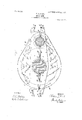
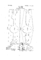
1 0 mi] Hilton 1"/1 nii/lf manera: eireular recesses Lland 5 to iit over the truck 5 Be it known that l, Ynaaiu el. linien, a axle t3 and with smaller :niproxiinately semicitizen ol' the lfnited States, and a resit'lent eireular recesses 7 and o' to tit over 4the armaot' Wilkinsburg, in the eount ol' Allegheny tute shaft 9. The opiioaite side of the gear 5 and State oi 1"enns \l\'ania, have invented a case. is provided with two similar plates it) new and usel'ul .lnipi'o\.'enieiit in (tear-Cases, and ll the blanks lor whit'h are shown, reol" whieh the i'oilowinif is a speeil'ieation. speetivelv, in Figs. -ll and 5 ol`v the drawings My invention relates to fear eases enibut as the armature sljud't does not'` pri'ijeet ployed lor iuelosinej and protecting the Agear through this side of the gear ease, the blanks 1o' `Wheels and pinions used for tmnsniittinf;l are provided with only 'the soun-eu'eular repower at reduced speeds from railwa)Y motor eesses i2 and '13 for the truek axle (i. The armatures to the trueknxles o|` the vehicles blank 3 is provided with upwardly projecting in eonneetion with which thei` are used. lips l-l and l5 at its respeetive ends and with The ohjeet ol my -invention istoprovide a similar lips 16 and .i7 adjaeeul to the recess i5 geaiease whirh shail be simple and inex- 5. The blank ll is similarly provided with pensive in eonstruetion, light in weight and lips 18 and 10 adjacent toits ends and lips 7o durable in serviee. 2() and 2l. adjacent to its reeess l. The llecetofore it` has been the usual praetiee to blank 2 is provided with a transverse out 22 Construct railwa motor gear eases ol` inallethat extends inward for a considerable dis- 2o able iron castings thougrh ii has been also tancel from its lower edge adjaeent to one proposed to minul'aotiue them oi pressed end and a similar eut 23 adjacent lo its other 75 steek The malleable iron castings whieh end. The blank 1l is similari)v provided havefbeen usuali)V employed have been ot' unwith ents 24 and 25 adjacent 'to its respective desirable weight: and liable to breakage in ends. 2 5 serviee, and pressed steel gear eases have.L The body portion of the gear ease oom been diilicnlt audexpensive to manuhieture. prises two plates 2G and 27 oi thin sheet So In the aeeou'nnniying` drawings, Figure l Ametal such, for example, as terne plate at the is a View in side elevation of a gear viase conside provitled with plates 2 and and with struc-,ted vin aeeordauee with in v invention, similar plates 28 and 29 at the opposite side. 3 the. arnar-ure shal't and the trunk axley being The adjaeent edges of the thin plates 26 and shown in section. liig. 2 is an end elevation 27 are bent over the edges ol' the plates 2 85 ol a portion of the gear ease slmwn .in Fig. 1. and 3 as indicated at 30 and 31 and are Fig. 3 is a side elevation ol one ol' the upper riveted thereto. The adjaeent edges of the blanks used in making` the rear ease. li'ipzfi plates 2S and are bent or iolded over tl'e 35 is a side elevation oi the other upper blank. corresponding edges of the plaies 10 and I1 Fie; :'i is a side elevation ot' the lower blank as indicated at 32 and 33% and are riviped 9o l'o.- the saine side as the upper blank shown thereto The plates 26 and 27 and 28 and in File; 4, and Fig'. t3 is. a side elevation of the 29 are also securely riveted to the eorrelower blank lor the same side as the. blank spending' plates 2 and 3 and it) and l1 alongA 4o slio.\'n'i11lt`i}.. 5. their respective upper and lower edges, at
The gear 'ase 1 which is eonstrueted in aetheir ends and around the openiings l'ornied 95 eor'dunee with my invention is or ma),-Y he of by 'the recesses 4l and 5, 7 and f and l2 the usual l'orm or contour but it. is built up of and 13. a piuralitr ol'` nieta-l plates whieh will be now rllhe. lips l() and 17 and 2U and l are bent .i described in detail without the intention outward slifhtlir so as to no'eeialong side I i h however, oi li-.nitingtheinvention to deriees the eorreslnnnling plates 2 and 1t). The ioo or parts ol the oXaet loi-in or dinunsions portions 34, 35, liti and 37, formed respecshownin the drawings. l tively, by the outs 22, 23, 24 and 25, are At the side next the motor armature the bent-over substantially at right angles to 5C ease is provided with two plates 2 and 2) ol l the side fat-es ot' the plates, and the lips i4.
eoniparativelythick sheet metal, i,u'el'erabl v i5, i8 and 1t) are similarly bent-over at m5 steel; these plates, the blanks l'or which are right angles to they side l'aees ol' the plates, shown, respectively, in Figs, 253 and t3, are sovlI 'l`o the bent-over ptnftions 2H und 3o and also l orally provided with. approxinuitely sentito thel adjacent, unbent portions is riveted a channel piece 38. To the bent-over lips 14 and 1S and to the adjacent unbent portions Yat the same end is riveted a similar channel `gear case comprises an upper sheet metal strip 42 which may he terne plate or other thin materialand a lower strip 43 of like or similar material. The meeting edges of the strip 42 and the plates 26 and 28 are folded together as indicated at 44 and 45 and the meeting edges of the strip 43 and plates 27 and 29 are similarly folded together as indicated at 46 and 47 and these joints are preferably soldered in order to malte them oil tight. The respective ends ol the strip 43 are folded around the ends of the bracing structure as indicated at 48' amt-49 and the edg'es of the upper strip`42 are folded so as to rest upon the corresponding portion of the strip 43 as indicated at 50 and 51. The upper side of the. gear case may he provided `with a hinged door 52 in order that a suitable lu` bricant may be applied to the gears Without disinenibering the casing.
It will he understood from the foregoing description that the principal portions of the gear cases are of exceptionallythin, light weight metal and that the side plates of heavy metal that are riveted to the thin plates, are of suflicient rigidity to provide suitable supporting connections at the ends and to also preserve the form of the gear case under such strains as it may meet in service.
The form of the device and its structural details may, of course, he varied Within considerable limits without departing from my invention.
I claim as my invention.
1. A gear case for railway motors comprising a body portion, made up of thin metal plates, having their meeting edges :folded together and side plates of heavier metal riveted to the thin side plates.
2. A gear case for electric railway motors comprising side and edge plates of thin sheet metal, suitably fastened together at their edges and re-inforcing side metal riveted to the thin side plates.
3. gear case for electric railwa f motors comprising side and edge plates of thin sheet metal, fastened together at theirnin'eeting plates of thickeredges and side plates of heavier metal riveted to the thin side plates and having bent-.over end sections and re-inforcing hars or plates therefor.
4. A gear casing for electric railway motors comprising thin sheet metal sides and edge plates, having their meetingedgesfolded together and side plates of heavier metal riveted to the thin side plates and having reinforcing plates riveted to their ends.
A gear casing comprising side plates and top, bottom and end metal and side plates of relatively thick material riveted to the thin side plates. Y
6. A gear casing comprising four plane side plates and two curved plates l'or the top, bottom and ends, all voll thin sheet metal, and four re-inlorcing side plates of relatively thick material that are riveted tothe thin side plates. l A,
7. A gear casing composed ol: thin/'metal ripheral plates of sheet metal. and relatively thick and rigid re-inforcing plates that eX- tend along the adjacent edges of each pair of side plates and lool-.h edges of which are rivetedV thereto. f
1l. A gear casini! comprising edge plates of thin sheet meta and four side plates of thin sheet metal provided with a corresponding number ofrelatively narrovv re-intoreing plates of thick, rigid material that are riveted to thc respective thin plates adjacent to their contiguous edges. 4
in' testimony whereof, have. hereunto suhscrihed my name this `27th day of May, 1905 WILLIAM J. REICH.
Vlfitnesses:
BIRNEY lliNEs,
J (l. Mensa.
plates of thin, sheet plates the meeting edges 'ofwliich are folded 10. A gear casing comprising side and pe-v ICO
Priority Applications (1)
| Application Number | Priority Date | Filing Date | Title |
|---|---|---|---|
| US26349505A US856422A (en) | 1905-06-02 | 1905-06-02 | Gear-case. |
Applications Claiming Priority (1)
| Application Number | Priority Date | Filing Date | Title |
|---|---|---|---|
| US26349505A US856422A (en) | 1905-06-02 | 1905-06-02 | Gear-case. |
Publications (1)
| Publication Number | Publication Date |
|---|---|
| US856422A true US856422A (en) | 1907-06-11 |
Family
ID=2924877
Family Applications (1)
| Application Number | Title | Priority Date | Filing Date |
|---|---|---|---|
| US26349505A Expired - Lifetime US856422A (en) | 1905-06-02 | 1905-06-02 | Gear-case. |
Country Status (1)
| Country | Link |
|---|---|
| US (1) | US856422A (en) |
-
1905
- 1905-06-02 US US26349505A patent/US856422A/en not_active Expired - Lifetime
Similar Documents
| Publication | Publication Date | Title |
|---|---|---|
| US5027A (en) | Box fob jotjbnals | |
| US856422A (en) | Gear-case. | |
| US1180A (en) | Springs for railroad-cars | |
| US700172A (en) | Car-truck. | |
| US1278969A (en) | Journal-box. | |
| US1220018A (en) | Coal-car. | |
| US1120639A (en) | Car-truck. | |
| US684626A (en) | Truck-bolster for railway-cars. | |
| US1063867A (en) | Forged car-truck side frame. | |
| US869651A (en) | Bolster. | |
| GB191515182A (en) | Improvements in or relating to Bearing Spring Arrangements for Railway Vehicles. | |
| US1222931A (en) | Car-truck. | |
| US1300302A (en) | Dynamo-electric machine. | |
| US987014A (en) | Car-truck side frame. | |
| US408033A (en) | Kenzie hughes | |
| US793516A (en) | Car-truck bolster. | |
| GB191500320A (en) | Improvements in or relating to Side Carriers or Side Carriages for Cycles, Motor Cycles and the like. | |
| GB126636A (en) | Improvements in or relating to Journal Boxes for Railway Carriages and the like. | |
| US850902A (en) | Car-bolster. | |
| US1668178A (en) | Motor vehicle | |
| US753289A (en) | Car-bolster | |
| US1536136A (en) | Railroad car | |
| US906362A (en) | Tram-car or other like vehicle. | |
| USD44157S (en) | Worth | |
| US1290214A (en) | Rocker side bearing. |