US8558939B2 - Image pickup lens and image pickup apparatus - Google Patents
Image pickup lens and image pickup apparatus Download PDFInfo
- Publication number
- US8558939B2 US8558939B2 US13/501,678 US201013501678A US8558939B2 US 8558939 B2 US8558939 B2 US 8558939B2 US 201013501678 A US201013501678 A US 201013501678A US 8558939 B2 US8558939 B2 US 8558939B2
- Authority
- US
- United States
- Prior art keywords
- lens
- image pickup
- image
- surface facing
- object side
- Prior art date
- Legal status (The legal status is an assumption and is not a legal conclusion. Google has not performed a legal analysis and makes no representation as to the accuracy of the status listed.)
- Active
Links
Images
Classifications
-
- G—PHYSICS
- G02—OPTICS
- G02B—OPTICAL ELEMENTS, SYSTEMS OR APPARATUS
- G02B13/00—Optical objectives specially designed for the purposes specified below
- G02B13/001—Miniaturised objectives for electronic devices, e.g. portable telephones, webcams, PDAs, small digital cameras
- G02B13/0015—Miniaturised objectives for electronic devices, e.g. portable telephones, webcams, PDAs, small digital cameras characterised by the lens design
- G02B13/002—Miniaturised objectives for electronic devices, e.g. portable telephones, webcams, PDAs, small digital cameras characterised by the lens design having at least one aspherical surface
- G02B13/0035—Miniaturised objectives for electronic devices, e.g. portable telephones, webcams, PDAs, small digital cameras characterised by the lens design having at least one aspherical surface having three lenses
Definitions
- the present invention relates to an image pickup lens suitable for an image pickup apparatus employing a solid-state image pickup element such as a CCD (Charge Coupled Devices) type image sensor and a CMOS (Complementary Metal-Oxide Semiconductor) type image sensor, and to an image pickup apparatus.
- a solid-state image pickup element such as a CCD (Charge Coupled Devices) type image sensor and a CMOS (Complementary Metal-Oxide Semiconductor) type image sensor
- compact and thin image pickup apparatuses each employing a solid-state image pickup element such as a CCD type image sensor and a CMOS type image sensor have come to be mounted on mobile terminals being compact and thin electronic devices such as a cell phone and PDA (Personal Digital Assistant), and further on note PCs, which allows mutual transmission not only of sound information but also of image information to a remote location.
- Such the image pickup apparatuses are strongly demanded to be downsized and to handle high quality images realizing image quality expected by users.
- a solid-state image pickup element and an image pickup lens are main components constructing an image pickup apparatus.
- a solid-state image pickup element many apparatuses use a device such as a CCD type image sensor and a CMOS type image sensor, In recent years, downsizing of pixel pitch of a solid-state image pickup element has been advanced, and high resolution and high performance are being achieved by using the increased number of pixels. On the other hand, downsizing of a solid-state image pickup element is being achieved by keeping the number of pixels.
- Patent Literature 1 an image pickup lens which has a three-lens structure and includes a first lens and second lens both having positive power, has been proposed as disclosed in Patent Literature 1. Further, an image pickup lens wherein a second lens is negative has been proposed as shown in Patent literatures 2 to 4.
- Patent Literature 1 JP-A No. 2005-17884
- Patent Literature 2 JP-A No. 2007-156277
- Patent Literature 3 JP-B No. 4256442
- Patent Literature 4 JP-A No. 2005-308800
- the present invention has been achieved in view of such the problems and is aimed to provide an image pickup lens which has a three-lens structure, and an image pickup apparatus using the image pickup lens.
- the image pickup lens various aberrations are corrected satisfactorily, while a smaller size than the conventional image pickup lenses is achieved.
- the present invention is aimed to achieve downsizing at the level satisfying the following expression (I). TL/2Y′ ⁇ 0.9 (I)
- TL is a distance on the optical axis from the lens surface arranged at the closest position to the object side in the total system of the image pickup lens to the focal point at the image side
- 2 Y′ is a diagonal length of an image pickup plane of a solid-state image pickup element (a diagonal length of a rectangular effective pixel area of the solid-state image pickup element). Satisfying the range allows to downsize the whole image pickup apparatus and reduce the outer diameter of the lens as a synergy effect. Thereby, the image pickup apparatus can be reduced in size and weight as a whole.
- “focal point at the image side” means an image point formed when a parallel ray which is parallel with the optical axis enters a lens.
- an a parallel flat plate such as an optical low-pass filter, an infrared cut-off filter, a band-pass filter and a sealing glass of a solid-state image pickup element package, at a position between the lens surface arranged at the closest position to the image side in the image pickup lens and the focal point at the image side, the value of TL is calculated on the assumption that a space of the parallel flat plate is regarded as an air-equivalent distance.
- An image pickup lens described as an aspect of the present invention is an image pickup lens characterized by comprising, in order from an object side thereof, an aperture stop, a first lens, a second lens and a third lens, wherein the first lens is a positive lens and is a meniscus lens having a convex surface facing the object side and a concave surface facing an image side, the second lens is a lens including a concave surface facing the object side, the third lens is a negative lens, and the image pickup lens satisfies the following conditional expressions. 0.10 ⁇ D4/f ⁇ 0.25 (1) 0.00 ⁇
- D 4 is a distance (mm) of an air gap on an optical axis between the second lens and the third lens
- f is a focal length (mm) of a total system of the image pickup lens
- f 2 is a focal length (mm) of the second lens
- r 3 is a curvature radius (mm) of the surface facing the object side of the second lens.
- a basic construction of the present invention for obtaining a compact image pickup lens with excellently corrected aberrations is composed of, in order from the object side, an aperture stop, a first lens having a positive refractive power and having a meniscus shape including a convex surface facing the object side and a concave surface facing the image side, a second lens including a concave surface facing the object side, and a third lens having negative refractive power.
- This lens construction is advantageous in downsizing the total length of the image pickup lens because the first surface is convex toward the object side and the second surface is concave toward the image side in the first lens.
- the third lens being a negative lens makes the Petzval sum small, and enables to obtain an image pickup lens in which an excellent image-forming property is kept up to the periphery.
- an aperture stop By arranging an aperture stop at a position closer to the object side than the object-side surface of the first lens, the position of the exit pupil can be located farther than an image pickup plane. Therefore, the total length can be reduced, while telecentric property (hereinafter, is referred as “telecentricity”) is kept to be excellent
- the lens constriction relating to the present invention is made up of a thin positive lens which is composed of the first lens and the second lens, and a thin negative lens which is composed of the third lens.
- the total length of the lens is provided by the following expression, where fl 2 is a focal length of the first compound lens, d is a distance between the two compound lenses, fB is a distance (back focal length) from the second compound lens to the image plane.
- the expression (7) shows that the total length can be more reduced as the distanced between the compound lens composed of the first lens and the second lens, and the third lens is greater.
- the expression (7) shows that the total length can be more reduced as the composite focal length fl 2 of the first lens and second lens is smaller.
- Conditional expression (1) is a conditional expression for shortening the total length of the image pickup lens.
- distance D 4 is preferably set to be broad.
- the value of D 4 /f of Conditional expression (1) exceeds the upper limit, a bundle of axial rays entering the third lens becomes excessively thin and longitudinal chromatic aberration is hardly corrected in an excellent condition. Further, the height of off-axis rays entering the third lens becomes high and it makes the diameter of the third lens large, which is disadvantageous in making the lens compact
- the value of D 4 /f of Conditional expression (1) is lower than the lower limit, the total lens length is hardly reduced effectively. Therefore, it is preferable that Conditional expression (1) is satisfied. Further, the range of the following expression (1′) is more preferable. 0.10 ⁇ D4/f ⁇ 0.20 (1′) (Effects of Conditional Expression (2))
- Conditional expression (2) is a conditional expression for shortening the total length of the image pickup lens.
- the composite focal length fl 2 of the first lens and the second lens is required to be reduced.
- it can be considered to strengthen the power of the first lens firstly.
- an increase of the power of the first lens enlarges spherical aberration and coma to be generated at an off-axis area, and they are not corrected sufficiently with the succeeding lens.
- the second lens with weaker power makes composite focal length fl 2 smaller and makes the total length shorter.
- the power of the second lens is positive, the second lens with greater power is advantageous in decreasing the total length, but excessively strong power of the second lens makes longitudinal chromatic aberration insufficiently corrected and further makes Petzval sum great so that curvature of field cannot be corrected.
- the power of the second lens is weaker whether the power is positive or negative, for reducing the total length with correcting the longitudinal aberration and curvature of field. Therefore, it is preferable that Conditional expression (2) is satisfied. Further, the range of the following expression (2′) is more preferable. 0.00 ⁇
- Conditional expression (3) is a conditional expression for correcting coma excellently at the intermediate image height with reducing the total length of the image pickup lens.
- curvature radius of a convex surface is positive and the curvature radius of a concave surface is negative.
- An image pickup lens as another aspect of the present invention is that the above image pickup lens is characterized in that at least a surface facing the image side of the third lens is an aspheric surface, and the aspheric surface includes at least one aspheric-surface inflection point.
- an inflection point means a point on an aspheric surface such that a tangential plane at a peak of the aspheric surface becomes perpendicular to the optical axis on a curve of the sectional shape of the lens within the effective radius.
- An image pickup lens as another aspect of the present invention is that the above image pickup lens is characterized in that the third lens is a negative meniscus lens in which a convex surface faces the object side in a paraxial region thereof.
- the position of the principal point of the third lens being a negative lens is located closer to the image side, which enlarges distanced of the compound lens of the first lens and the second lens, and the third lens in the above expression (7), and enables to reduce the total lens length L.
- An image pickup lens as another aspect of the present invention is that the above image pickup lens is characterized by satisfying the following expression (4). ⁇ 1.00 ⁇ f3/f ⁇ 0.00 (4)
- f 3 is a focal length (mm) of the third lens.
- Conditional expression (4) is a conditional expression for correcting various aberrations excellently with reducing the total length of the image pickup lens.
- the third lens as a negative lens having stronger power can keep longitudinal chromatic aberration and curvature of field smaller.
- the third lens having weaker power can keep telecentricity more excellently. Therefore, it is important to adjust the balance of them.
- the value of f 3 /f becomes lower than the lower limit of Conditional expression (4), it is advantageous in aberration correction but the total length becomes excessively long, which is disadvantageous in downsizing.
- the value of f 3 /f exceeds the upper limit of Conditional expression (4), aberration correction becomes insufficient. Therefore, it is preferable that the conditional expression (4) is satisfied.
- An image pickup lens as another aspect of the present invention is that the above image pickup lens is characterized by satisfying the following expression (5). ⁇ 1.90 ⁇ f/r4 ⁇ 0.40 (5)
- r 4 is a curvature radius (mm) of a surface facing the image side of the second lens.
- Conditional expression (5) is a conditional expression for correcting various aberrations excellently with reducing the total length of the image pickup lens.
- a lens in which Petzval sum and chromatic aberrations are corrected can be obtained, while the total length is kept to be small, by setting the value of r 4 to satisfy Conditional expression (5).
- the value of r 4 is positive, the negative power of the second lens becomes greater as the value of r 4 becomes smaller, which makes correction of various aberrations easy.
- the value exceeds the upper limit of Conditional expression (5) the total length becomes excessively large.
- An image pickup lens as another aspect of the present invention is that the above image pickup lens is characterized in that the second lens satisfies the following expression (6). 1.55 ⁇ n2 (6)
- n2 is a refractive index of the second lens.
- Conditional expression (6) is a conditional expression for correcting coma excellently with reducing the total length of the image pickup lens.
- An image pickup lens as another aspect of the present invention is that the above image pickup lens is characterized in that each of the first lens, the second lens and the third lens is formed of a heat-resistant material.
- each of the first lens, the second lens and the third lens can be used for a so-called reflow processing that electric parts and lens modules are mounted on a substrate at the same time in a high-temperature reflow furnace. Therefore, a large number of image pickup apparatuses can be produced at low cost
- the heat-resistant material is preferably a heat-resistant glass.
- An image pickup apparatus as another aspect of the present invention is characterized by comprising any one of the above image pickup lenses and a solid-state image pickup element.
- a three-element image pickup lens which is smaller than the conventional image pickup lenses and exhibits excellently corrected various aberrations, and an image pickup apparatus equipped with the image pickup lens.
- FIG. 1 shows a perspective view illustrating an image pickup apparatus 50 relating to the present embodiment.
- FIG. 2 shows a sectional view illustrating the structure of FIG. 1 which is cut along arrowed lines II-II, and is viewed in the direction of the arrows.
- FIGS. 3 a and 3 b shows a condition that image pickup apparatus 50 is mounted on cell phone 100 as a mobile terminal.
- FIG. 4 shows a control block diagram of cell phone 100 .
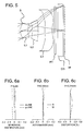
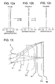
- FIG. 5 shows a sectional view of the image pickup lens of Example 1.
- FIGS. 6 a , 6 b , and 6 c show aberration diagrams of spherical aberration, astigmatism, and distortion of the image pickup lens of Example 1.
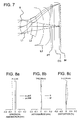
- FIG. 7 shows a sectional view of the image pickup lens of Example 2.
- FIG. 8 a , 8 b , and 8 c show aberration diagrams of spherical aberration, astigmatism, and distortion of the image pickup lens of Example 2.
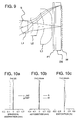
- FIG. 9 shows a sectional view of the image pickup lens of Example 3.
- FIGS. 10 a , 10 b , and 10 c show aberration diagrams of spherical aberration, astigmatism, and distortion of the image pickup lens of Example 3.
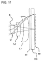
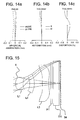
- FIG. 11 shows a sectional view of the image pickup lens of Example 4.
- FIGS. 12 a , 12 b , and 12 c show aberration diagrams of spherical aberration, astigmatism, and distortion of the image pickup lens of Example 4.
- FIG. 13 shows a sectional view of the image pickup lens of Example 5.
- FIGS. 14 a , 14 b , and 14 c show aberration diagrams of spherical aberration, astigmatism, and distortion of the image pickup lens of Example 5.
- FIG. 15 shows a sectional view of the image pickup lens of Example 6.
- FIGS. 16 a , 16 b , and 16 c show aberration diagrams of spherical aberration, astigmatism, and distortion of the image pickup lens of Example 6.
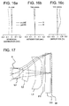
- FIG. 17 shows a sectional view of the image pickup lens of Example 7.
- FIGS. 18 a , 18 b , and 18 c show aberration diagrams of spherical aberration, astigmatism, and distortion of the image pickup lens of Example 7.
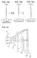
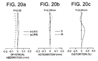
- FIG. 19 shows a sectional view of the image pickup lens of Example 8.
- FIGS. 20 a , 20 b , and 20 c show aberration diagrams of spherical aberration, astigmatism, and distortion of the image pickup lens of Example 8.
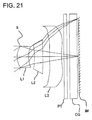
- FIG. 21 shows a sectional view of the image pickup lens of Example 9.
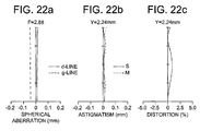
- FIGS. 22 a , 22 b , and 22 c show aberration diagrams of spherical aberration, astigmatism, and distortion of the image pickup lens of Example 9.
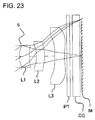
- FIG. 23 shows a sectional view of the image pickup lens of Example 10.
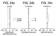
- FIGS. 24 a , 24 b , and 24 c show aberration diagrams of spherical aberration, astigmatism, and distortion of the image pickup lens of Example 10.
- FIG. 1 is a perspective view of image pickup apparatus 50 relating to the present embodiment.
- FIG. 2 is a sectional view illustrating the structure of FIG. 1 which is cut along arrowed lines II-II and is viewed in the arrowed direction.
- image pickup apparatus 50 includes CMOS type image sensor 51 as a solid-state image pickup element having photoelectric conversion section 51 a ; image pickup lens 10 for forming a subject image onto photoelectric conversion section 51 a of the image sensor 51 ; substrate 52 supporting image sensor 51 and including an external connecting terminal (which is unillustrated) for transmitting and receiving electric signal of the image sensor 51 . They are integrally formed in one body.
- the above image sensor 51 includes photoelectric conversion section 51 a representing a light-receiving section, on the central portion of a surface on the light-receiving side of the image sensor 51 , and is connected to a signal processing circuit which is not illustrated, wherein on the photoelectric conversion section 51 a , pixels (photoelectric conversion elements) are arranged on a two-dimensional basis.
- the signal processing circuit is composed of a drive circuit section that obtains signal electric charges by driving respective pixels in succession, A/D converting section that converts each signal electric charge into digital signal and of a signal processing section that forms an output of image signal by using the digital signal.
- the image pickup element 51 converts the signal charges from the photoelectric conversion section 51 a into image signal such as digital YUV signal, and outputs it to a predetermined circuit on substrate 52 through wires (which are not illustrated).
- Reference sign Y represents luminance signal
- the solid-state image pickup element is not limited to the above-described CMOS type image sensor, but another element such as a CCD can be employed.
- Substrate 52 supporting image sensor 51 is connected to image sensor 51 with wires which are not illustrated so as to enable communication between them.
- Substrate 52 is connected with an external circuit (for example, a control circuit provided by the higher level of apparatus of a mobile terminal on which the image pickup apparatus is mounted) through an unillustrated external connecting terminal, which enables to receive voltage and clock signal for driving image sensor 51 from the external circuit and to output the digital YUV signal to the external circuit.
- an external circuit for example, a control circuit provided by the higher level of apparatus of a mobile terminal on which the image pickup apparatus is mounted
- image sensor 51 is covered and sealed with cover glass CG which is attached to lower lens frame 20 in a rectangular tube (or a cylindrical) shape. Further, above cover glass CG, plate PT such as an infrared cut-off filter is fixed to lower lens frame 20 .
- the lower end of lower lens frame 20 holding the edges of glass cover CG and plate PT is fixed to the upper surface of substrate 52 with surrounding image sensor 51 .
- the upper end of lower lens frame 20 is connected with the lower and of upper lens frame 21 with being fitted into the upper lens frame.
- Upper lens frame 21 is hollow and includes flange section 21 a extending inside in the direction perpendicular to the optical axis, on its upper end.
- Image pickup lens 10 is arranged inside the flange section with being fitted to the flange section.
- Image pickup lens 10 is composed of, in order from the object side (upward in FIG. 2 ), aperture stop formed by an opening of flange section 21 a , first lens L 1 having positive refractive power and having a meniscus shape with a convex surface facing the object side and a concave surface facing the image side, second lens L 2 including a concave surface facing the object side, and third lens L 3 having negative refractive power.
- Each of lenses L 1 to L 3 is preferably formed of a heat-resistant material, for example a glass material.
- the top surface of flange section L 1 a of first lens L 1 comes in contact with the bottom surface of flange section 21 a of upper lens frame 21 .
- the top surface of flange section L 2 a of second lens L 2 comes in contact with the bottom surface of flange section L 1 a of first lens L 1 directly with supporting light-shielding member SH in a ring plate shape between the surfaces.
- the bottom surface of flange section L 2 a of second lens L 2 comes in contact with the top surface of fixing member SP which is attached to upper lens frame 20 , has a ring plate shape and doubles as a spacer.
- the top surface of flange section L 3 a , of third lens L 3 comes in contact with the bottom surface of the fixing member SP.
- the following expressions (1) to (3) hold, where D 4 is a distance (mm) of an air gap on an optical axis between second lens L 2 and third lens L 3 , f is a focal length (mm) of the total system of the image pickup lens, f 2 is a focal length (mm) of second lens L 2 , and r 3 is a curvature radius (mm) of the surface facing the object side of the second lens. 0.10 ⁇ D4/f ⁇ 0.25 (1) 0.00 ⁇
- lower lens frame 20 to which plate PT has been joined is joined and bonded to substrate 52 so as to cover CMOS type image sensor 51 which has been arranged on substrate 52 , and upper lens frame 21 in which first lens L 1 , light-shielding member SH, second lens L 2 , fixing member SP, third lens L 3 are inserted in this order is bonded to lower lens frame 20 .
- the assembling embodiment is not limited to the above.
- the resulting body may be bonded to substrate 52 so as to cover CMOS type image sensor 51 which has been arranged on substrate 52 .
- FIGS. 3 a and 3 b are diagram showing a condition that image pickup apparatus 50 is mounted on cell phone 100 as a mobile terminal.
- FIG. 4 is a control block diagram of cell phone 100 .
- image pickup apparatus 50 as shown in FIGS. 3 a and 3 b , for example, the object-side end surface of the image pickup lens is arranged on the rear surface (where it is assumed that the side of liquid crystal display section is the front) of cell phone 100 , so as to be located at a position corresponding to an area below the liquid crystal display section.
- the arrangement of image pickup apparatus 50 is not limited to that.
- the external connecting terminal (which is unillustrated) of image pickup apparatus 50 is connected with control section 101 of cell phone 100 to output image signals such as luminance signal and color difference signal to control section 101 .
- cell phone 100 is provided with: control section (CPU) 101 which centrally controls respective sections and executes programs corresponding to various processing, input section 60 for indicating and inputting information such as number; display section 70 for displaying predetermined data and picked-up images; radio communication section 80 for realizing various kinds of information communication to an external server; storage section (ROM) 91 which stores system programs of the cell phone 100 , various processing programs, and necessary data such as terminal ID; and temporary storage section (RAM) 92 which temporarily stores various processing programs and data to be processed by control section 101 , processed data, and image data from the image pickup apparatus 50 and is used as a working area.
- control section (CPU) 101 which centrally controls respective sections and executes programs corresponding to various processing
- input section 60 for indicating and inputting information such as number
- display section 70 for displaying predetermined data and picked-up images
- radio communication section 80 for realizing various kinds of information communication to an external server
- storage section (ROM) 91 which stores system programs of the cell phone 100 , various processing programs, and necessary data such
- Image signal inputted from image pickup apparatus 50 is stored in nonvolatile storage section (flash memory) 93 , is displayed on display section 70 , or is transmitted to the outside as image information through radio communication section 80 , by the control section 101 of cell phone 100 .
- cell phone 100 includes a microphone and speaker for inputting and outputting voices, which are not illustrated.
- image signal of a still image or movie is captured in image sensor 51 .
- the photographer pushes button BT in input section 60 shown in FIG. 3 a at the desired timing of shooting, the shutter is released, which results in capturing image signal in image pickup apparatus 50 .
- the image signal inputted in image pickup apparatus 50 is transmitted to the control section in the above-described cell phone 100 , to be stored in nonvolatile storage section 93 , be displayed in display section 70 or be transmitted outside as image information through radio communication section 80 .
- Nd Refractive index of a lens material for d-line
- EXTP Position of the exit pupil under the condition that the rearmost surface of the image pickup optical system is assumed to be the basis
- a surface represented by a surface number followed by an asterisk “*” is a surface having an aspheric shape.
- the shape of the aspheric surface is expressed by the following Math. 1, where the peak of the surface is defined as the origin, X-axis extends along the optical axis direction, and h represents the height in a direction perpendicular to the optical axis.
- the power of 10 for example, 2.5 ⁇ 10 ⁇ 02
- E for example, 2.5E-02
- a blank in numerical data in Tables represents zero.
- a i is i-th-order aspheric surface coefficient
- R is a curvature radius
- K is a conic constant
- FIG. 5 shows a sectional view of the image pickup lens of Example 1.
- S represents an aperture stop
- L 1 represents the first lens having positive refractive power and having a meniscus shape with a convex surface facing the object side and a concave surface facing the image side
- L 2 represents the second lens having negative refractive power and having a meniscus shape with a concave surface facing the object side and a convex surface facing the image side
- L 3 represents the third lens having negative refractive power, having a meniscus shape with a convex surface facing the object side, and including an inflection point on each of the object-side surface and the image-side surface
- PT represents a parallel flat plate which is assumed to be a component such as an optical low-pass filter and IR cut-off filter
- CG represents a parallel flat plate which is assumed to be a component such as a seal glass of a solid-state image pickup element
- IM represents a solid-state image pickup element.
- FIGS. 6 a , 6 b , and 6 c show aberration diagrams of spherical aberration, astigmatism, and distortion of the image pickup lens of Example 1.
- a dashed line and a solid line represent the amounts of spherical aberration for g-line and d-line, respectively.
- the solid line represents a sagittal plane and the dashed line represents a meridional plane.
- FIG. 7 shows a sectional view of the image pickup lens of Example 2.
- S represents an aperture stop
- L 1 represents the first lens having positive refractive power and having a meniscus shape with a convex surface facing the object side and a concave surface facing the image side
- L 2 represents the second lens having positive refractive power and having a meniscus shape with a concave surface facing the object side and a convex surface facing the image side
- L 3 represents the third lens having negative refractive power, having a meniscus shape with a convex surface facing the object side, and including an inflection point on each of the object-side surface and the image-side surface
- PT represents a parallel flat plate which is assumed to be a component such as an optical low-pass filter and IR cut-off filter
- CG represents a parallel flat plate which is assumed to be a component such as a seal glass of a solid-state image pickup element
- IM represents a solid-state image pickup element.
- FIGS. 8 a , 8 b , and 8 c show aberration diagrams of spherical aberration, astigmatism, and distortion of the image pickup lens of Example 2.
- a dashed line and a solid line represent the amounts of spherical aberration for g-line and d-line, respectively.
- the solid line represents a sagittal plane and the dashed line represents a meridional plane.
- FIG. 9 shows a sectional view of the image pickup lens of Example 3.
- S represents an aperture stop
- L 1 represents the first lens having positive refractive power and having a meniscus shape with a convex surface facing the object side and a concave surface facing the image side
- L 2 represents the second lens having negative refractive power and having a meniscus shape with a concave surface facing the object side and a convex surface king the image side
- L 3 represents the third lens having negative refractive power, including concave surfaces facing the object side and the image side, and including an inflection point on the image-side surface
- PT represents a parallel flat plate which is assumed to be a component such as an optical low-pass filter and IR cut-off filter
- CG represents a parallel flat plate which is assumed to be a component such as a seal glass of a solid-state image pickup element
- IM represents a solid-state image pickup element.
- FIGS. 10 a , 10 b , and 10 c show aberration diagrams of spherical aberration, astigmatism, and distortion of the image pickup lens of Example 3.
- a dashed line and a solid line represent the amounts of spherical aberration for g-line and d-line, respectively.
- the solid line represents a sagittal plane and the dashed line represents a meridional plane.
- FIG. 11 shows a sectional view of the image pickup lens of Example 4.
- S represents an aperture stop
- L 1 represents the first lens having positive refractive power and having a meniscus shape with a convex surface facing the object side and a concave surface facing the image side
- L 2 represents the second lens having negative refractive power and having a meniscus shape with a concave surface facing the object side and a convex surface facing the image side
- L 3 represents the third lens having negative refractive power, having a meniscus shape with a convex surface facing the object side, and including an inflection point on each of the object-side surface and the image-side surface
- PT represents a parallel flat plate which is assumed to be a component such as an optical low-pass filter and IR cut-off filter
- CG represents a parallel flat plate which is assumed to be a component such as a seal glass of a solid-state image pickup element
- IM represents a solid-state image pickup element.
- FIGS. 12 a , 12 b , and 12 c show aberration diagrams of spherical aberration, astigmatism, and distortion of the image pickup lens of Example 4.
- a dashed line and a solid line represent the amounts of spherical aberration for g-line and d-line, respectively.
- the solid line represents a sagittal plane and the dashed line represents a meridional plane.
- FIG. 13 shows a sectional view of the image pickup lens of Example 5.
- S represents an aperture stop
- L 1 represents the first lens having positive refractive power and having a meniscus shape with a convex surface facing the object side and a concave surface facing the image side
- L 2 represents the second lens having negative refractive power and having a meniscus shape with a concave surface facing the object side and a convex surface facing the image side
- L 3 represents the third lens having negative refractive power, having a meniscus shape with a convex surface facing the object side, and including an inflection point on each of the object-side surface and the image-side surface
- PT represents a parallel flat plate which is assumed to be a component such as an optical low-pass filter and a cut-off filter
- CG represents a parallel flat plate which is assumed to be a component such as a seal glass of a solid-state image pickup element
- IM represents a solid-state image pickup element.
- FIGS. 14 a , 14 b , and 14 c show aberration diagrams of spherical aberration, astigmatism, and distortion of the image pickup lens of Example 5.
- a dashed line and a solid line represent the amounts of spherical aberration for g-line and d-line, respectively.
- the solid line represents a sagittal plane and the dashed line represents a meridional plane.
- FIG. 15 shows a sectional view of the image pickup lens of Example 6.
- S represents an aperture stop
- L 1 represents the first lens having positive refractive power and having a meniscus shape with a convex surface facing the object side and a concave surface facing the image side
- L 2 represents the second lens having positive refractive power and having a meniscus shape with a concave surface facing the object side and a convex surface facing the image side
- L 3 represents the third lens having negative refractive power, having a meniscus shape with a convex surface facing the object side, and including an inflection point on each of the object-side surface and the image-side surface
- PT represents a parallel flat plate which is assumed to be a component such as an optical low-pass filter and IR cut-off filter
- CG represents a parallel flat plate which is assumed to be a component such as a seal glass of a solid-state image pickup element
- IM represents a solid-state image pickup element.
- FIGS. 16 a , 16 b , and 16 c show aberration diagrams of spherical aberration, astigmatism, and distortion of the image pickup lens of Example 6.
- a dashed line and a solid line represent the amounts of spherical aberration for g-line and d-line, respectively.
- the solid line represents a sagittal plane and the dashed line represents a meridional plane.
- FIG. 17 shows a sectional view of the image pickup lens of Example 7.
- S represents an aperture stop
- L 1 represents the first lens having positive refractive power and having a meniscus shape with a convex surface facing the object side and a concave surface facing the image side
- L 2 represents the second lens having positive refractive power and having a meniscus shape with a concave surface facing the object side and a convex surface facing the image side
- L 3 represents the third lens having negative refractive power, having a meniscus shape with a convex surface facing the object side, and including an inflection point on each of the object-side surface and the image-side surface
- PT represents a parallel flat plate which is assumed to be a component such as an optical low-pass filter and IR cut-off filter
- CG represents a parallel flat plate which is assumed to be a component such as a seal glass of a solid-state image pickup element
- IM represents a solid-state image pickup element.
- FIGS. 18 a , 18 b , and 18 c show aberration diagrams of spherical aberration, astigmatism, and distortion of the image pickup lens of Example 7.
- a dashed line and a solid line represent the amounts of spherical aberration for g-line and d-line, respectively.
- the solid line represents a sagittal plane and the dashed line represents a meridional plane.
- Table 8 shows lens data of Example 8.
- FIG. 19 shows a sectional view of the image pickup lens of Example 8.
- S represents an aperture stop
- L 1 represents the first lens having positive refractive power and having a meniscus shape with a convex surface facing the object side and a concave surface facing the image side
- L 2 represents the second lens having negative refractive power and including a concave surface facing the object side and a concave surface facing the image side
- L 3 represents the third lens having negative refractive power, having a meniscus shape with a convex surface facing the object side, and including an inflection point on each of the object-side surface and the image-side surface
- PT represents a parallel flat plate which is assumed to be a component such as an optical low-pass filter and IR cut-off filter
- CG represents a parallel flat plate which is assumed to be a component such as a seal glass of a solid-state image pickup element
- IM represents a solid-state image pickup element.
- FIGS. 20 a , 20 b , and 20 c show aberration diagrams of spherical aberration, astigmatism, and distortion of the image pickup lens of Example 8.
- a dashed line and a solid line represent the amounts of spherical aberration for g-line and d-line, respectively.
- the solid line represents a sagittal plane and the dashed line represents a meridional plane.
- FIG. 21 shows a sectional view of the image pickup lens of Example 9.
- S represents an aperture stop
- L 1 represents the first lens having positive refractive power and having a meniscus shape with a convex surface facing the object side and a concave surface facing the image side
- L 2 represents the second lens having negative refractive power and including a concave surface facing the object side and a concave surface facing the image side
- L 3 represents the third lens having negative refractive power, having a meniscus shape with a convex surface facing the object side, and including inflection points on the object-side surface and the image-side surface
- PT represents a parallel flat plate which is assumed to be a component such as an optical low-pass filter and IR cut-off filter
- CG represents a parallel fiat plate which is assumed to be a component such as a seal glass of a solid-state image pickup element
- IM represents a solid-state image pickup element.
- FIGS. 22 a , 22 b , and 22 c show aberration diagrams of spherical aberration, astigmatism, and distortion of the image pickup lens of Example 9.
- a dashed line and a solid line represent the amounts of spherical aberration for g-line and d-line, respectively.
- the solid line represents a sagittal plane and the dashed line represents a meridional plane.
- FIG. 23 shows a sectional view of the image pickup lens of Example 10.
- S represents an aperture stop
- L 1 represents the first lens having positive refractive power and having a meniscus shape with a convex surface facing the object side and a concave surface facing the image side
- L 2 represents the second lens having positive refractive power and having a meniscus shape with a concave surface facing the object side and a convex surface facing the image side
- L 3 represents the third lens having negative refractive power, including concave surfaces facing the object side and the image side and including inflection points on the image-side surface
- PT represents a parallel flat plate which is assumed to be a component such as an optical low-pass filter and IR cut-off filter
- CG represents a parallel flat plate which is assumed to be a component such as a seal glass of a solid-state image pickup element
- IM represents a solid-state image pickup element.
- FIGS. 24 a , 24 b , and 24 c show aberration diagrams of spherical aberration, astigmatism, and distortion of the image pickup lens of Example 10.
- a dashed line and a solid line represent the amounts of spherical aberration for g-line and d-line, respectively.
- the solid line represents a sagittal plane and the dashed line represents a meridional plane.
- Example 10 (1) D4/f 0.17 0.16 0.15 0.12 0.15 0.19 0.19 0.12 0.12 0.18 (2)
- each of the above examples is not designed such that an incident angle of a principal ray of the light flux that enters the image pickup plane of the solid-state image pickup element is always sufficiently small at a peripheral portion of the image pickup plane.
- a pitch of the arrangement of the color filter and the onchip-microlens-array is designed to be slightly smaller compared with a pixel pitch of the image pickup plane of the image pickup element, a light flux of oblique incidence can be guided to an light-receiving section of each pixel efficiently, because the color filter and the onchip-microlens-array are shifted greater toward an optical axis of an image pickup lens at the position which is closer to a peripheral portion of the image pickup plane. Owing to this, shading generated on solid-state image pickup element can be controlled to be small.
- the present examples provide design examples in which the above design requirement is lighten but further downsizing is aimed.
Landscapes
- Physics & Mathematics (AREA)
- General Physics & Mathematics (AREA)
- Optics & Photonics (AREA)
- Lenses (AREA)
Applications Claiming Priority (3)
| Application Number | Priority Date | Filing Date | Title |
|---|---|---|---|
| JP2009-239640 | 2009-10-16 | ||
| JP2009239640 | 2009-10-16 | ||
| PCT/JP2010/067533 WO2011046053A1 (ja) | 2009-10-16 | 2010-10-06 | 撮像レンズ及び撮像装置 |
Publications (2)
| Publication Number | Publication Date |
|---|---|
| US20120206639A1 US20120206639A1 (en) | 2012-08-16 |
| US8558939B2 true US8558939B2 (en) | 2013-10-15 |
Family
ID=43876104
Family Applications (1)
| Application Number | Title | Priority Date | Filing Date |
|---|---|---|---|
| US13/501,678 Active US8558939B2 (en) | 2009-10-16 | 2010-10-06 | Image pickup lens and image pickup apparatus |
Country Status (3)
| Country | Link |
|---|---|
| US (1) | US8558939B2 (ja) |
| JP (1) | JP5585586B2 (ja) |
| WO (1) | WO2011046053A1 (ja) |
Cited By (6)
| Publication number | Priority date | Publication date | Assignee | Title |
|---|---|---|---|---|
| US20140063623A1 (en) * | 2012-08-28 | 2014-03-06 | Kantatsu Co., Ltd. | Ultracompact image pickup lens |
| US20150077618A1 (en) * | 2013-09-18 | 2015-03-19 | Kabushiki Kaisha Toshiba | Imaging lens and solid state imaging device |
| US20180348488A1 (en) * | 2015-11-12 | 2018-12-06 | Konica Minolta, Inc. | Lens unit, imaging apparatus, and mobile device |
| US20210103124A1 (en) * | 2019-10-03 | 2021-04-08 | Largan Precision Co., Ltd. | Imaging optical system, imaging apparatus and electronic device |
| US20210208368A1 (en) * | 2019-05-27 | 2021-07-08 | Zhejiang Sunny Optics Co., Ltd. | Optical imaging lens assembly |
| US20210318525A1 (en) * | 2019-10-29 | 2021-10-14 | Jiangxi Lianchuang Electronic Co., Ltd. | Infrared optical imaging lens, camera module and driving monitor system |
Families Citing this family (8)
| Publication number | Priority date | Publication date | Assignee | Title |
|---|---|---|---|---|
| US8542310B2 (en) * | 2008-07-04 | 2013-09-24 | Konica Minolta Opto, Inc. | Imaging lens, manufacturing method and imaging unit therefor |
| US8292524B1 (en) * | 2011-08-05 | 2012-10-23 | Hon Hai Precision Industry Co., Ltd. | Lens module and camera module having same |
| TWI449946B (zh) * | 2011-12-19 | 2014-08-21 | Largan Precision Co Ltd | 成像鏡頭組 |
| CN102928959A (zh) * | 2012-10-20 | 2013-02-13 | 中山联合光电科技有限公司 | 一种高像素,体积小的光学系统 |
| WO2014165615A1 (en) * | 2013-04-03 | 2014-10-09 | Molex Incorporated | Expanded beam lens assembly |
| US11579410B2 (en) * | 2017-04-18 | 2023-02-14 | Zhejiang Sunny Optical Co., Ltd. | Camera lens assembly |
| JP7446994B2 (ja) * | 2018-06-08 | 2024-03-11 | ソニーセミコンダクタソリューションズ株式会社 | 撮像装置 |
| CN112236703B (zh) * | 2018-06-08 | 2024-01-16 | 索尼半导体解决方案公司 | 摄像装置 |
Citations (10)
| Publication number | Priority date | Publication date | Assignee | Title |
|---|---|---|---|---|
| KR20050017884A (ko) | 2003-08-11 | 2005-02-23 | 현대자동차주식회사 | V형 엔진의 체인 구동 시스템 |
| JP2005308800A (ja) | 2004-04-16 | 2005-11-04 | Seiko Precision Inc | 撮像レンズおよびこれを備えた撮像モジュール |
| JP2007156277A (ja) | 2005-12-07 | 2007-06-21 | Kyocera Corp | 撮像レンズ、光学モジュール、および携帯端末 |
| JP2008065305A (ja) | 2006-09-07 | 2008-03-21 | Largan Precision Co Ltd | 撮影用光学レンズ組 |
| JP2008070425A (ja) | 2006-09-12 | 2008-03-27 | Kyocera Corp | 撮像レンズ、光学モジュール、および携帯端末 |
| US20080170302A1 (en) * | 2006-04-14 | 2008-07-17 | Hye Jung Jeong | Lens Module and Camera Module |
| US20080291551A1 (en) * | 2007-03-30 | 2008-11-27 | Kenichi Sato | Imaging lens |
| JP2009092803A (ja) | 2007-10-05 | 2009-04-30 | Komatsulite Mfg Co Ltd | 撮像レンズ |
| US7830622B2 (en) * | 2006-03-28 | 2010-11-09 | Fujinon Corporation | Imaging lens |
| US20100328518A1 (en) * | 2008-09-03 | 2010-12-30 | Panasonic Corporation | Imaging lens and imaging device using the lens |
Family Cites Families (1)
| Publication number | Priority date | Publication date | Assignee | Title |
|---|---|---|---|---|
| JP5366314B2 (ja) * | 2009-06-29 | 2013-12-11 | 株式会社オプトロジック | 撮像レンズ |
-
2010
- 2010-10-06 US US13/501,678 patent/US8558939B2/en active Active
- 2010-10-06 WO PCT/JP2010/067533 patent/WO2011046053A1/ja active Application Filing
- 2010-10-06 JP JP2011536109A patent/JP5585586B2/ja active Active
Patent Citations (10)
| Publication number | Priority date | Publication date | Assignee | Title |
|---|---|---|---|---|
| KR20050017884A (ko) | 2003-08-11 | 2005-02-23 | 현대자동차주식회사 | V형 엔진의 체인 구동 시스템 |
| JP2005308800A (ja) | 2004-04-16 | 2005-11-04 | Seiko Precision Inc | 撮像レンズおよびこれを備えた撮像モジュール |
| JP2007156277A (ja) | 2005-12-07 | 2007-06-21 | Kyocera Corp | 撮像レンズ、光学モジュール、および携帯端末 |
| US7830622B2 (en) * | 2006-03-28 | 2010-11-09 | Fujinon Corporation | Imaging lens |
| US20080170302A1 (en) * | 2006-04-14 | 2008-07-17 | Hye Jung Jeong | Lens Module and Camera Module |
| JP2008065305A (ja) | 2006-09-07 | 2008-03-21 | Largan Precision Co Ltd | 撮影用光学レンズ組 |
| JP2008070425A (ja) | 2006-09-12 | 2008-03-27 | Kyocera Corp | 撮像レンズ、光学モジュール、および携帯端末 |
| US20080291551A1 (en) * | 2007-03-30 | 2008-11-27 | Kenichi Sato | Imaging lens |
| JP2009092803A (ja) | 2007-10-05 | 2009-04-30 | Komatsulite Mfg Co Ltd | 撮像レンズ |
| US20100328518A1 (en) * | 2008-09-03 | 2010-12-30 | Panasonic Corporation | Imaging lens and imaging device using the lens |
Cited By (11)
| Publication number | Priority date | Publication date | Assignee | Title |
|---|---|---|---|---|
| US20140063623A1 (en) * | 2012-08-28 | 2014-03-06 | Kantatsu Co., Ltd. | Ultracompact image pickup lens |
| US8902513B2 (en) * | 2012-08-28 | 2014-12-02 | Kantatsu Co., Ltd. | Ultracompact image pickup lens |
| US20150077618A1 (en) * | 2013-09-18 | 2015-03-19 | Kabushiki Kaisha Toshiba | Imaging lens and solid state imaging device |
| US9257470B2 (en) * | 2013-09-18 | 2016-02-09 | Kabushiki Kaisha Toshiba | Imaging lens and solid state imaging device |
| US20180348488A1 (en) * | 2015-11-12 | 2018-12-06 | Konica Minolta, Inc. | Lens unit, imaging apparatus, and mobile device |
| US11209631B2 (en) * | 2015-11-12 | 2021-12-28 | Konica Minolta, Inc. | Lens unit, imaging apparatus, and mobile device |
| US20210208368A1 (en) * | 2019-05-27 | 2021-07-08 | Zhejiang Sunny Optics Co., Ltd. | Optical imaging lens assembly |
| US11899168B2 (en) * | 2019-05-27 | 2024-02-13 | Zhejiang Sunny Optics Co., Ltd. | Optical imaging lens assembly |
| US20210103124A1 (en) * | 2019-10-03 | 2021-04-08 | Largan Precision Co., Ltd. | Imaging optical system, imaging apparatus and electronic device |
| US11480757B2 (en) * | 2019-10-03 | 2022-10-25 | Largan Precision Co., Ltd. | Imaging optical system, imaging apparatus and electronic device |
| US20210318525A1 (en) * | 2019-10-29 | 2021-10-14 | Jiangxi Lianchuang Electronic Co., Ltd. | Infrared optical imaging lens, camera module and driving monitor system |
Also Published As
| Publication number | Publication date |
|---|---|
| WO2011046053A1 (ja) | 2011-04-21 |
| JP5585586B2 (ja) | 2014-09-10 |
| US20120206639A1 (en) | 2012-08-16 |
| JPWO2011046053A1 (ja) | 2013-03-07 |
Similar Documents
| Publication | Publication Date | Title |
|---|---|---|
| US8558939B2 (en) | Image pickup lens and image pickup apparatus | |
| US8619175B2 (en) | Imaging lens, imaging device and portable terminal | |
| US8149523B2 (en) | Image pickup lens, image pickup apparatus and mobile terminal | |
| US9310582B2 (en) | Image pick-up lens, image pick-up device, portable terminal and digital instrument | |
| JP5440032B2 (ja) | 撮像レンズ及び小型撮像装置 | |
| US9013809B2 (en) | Image capturing lens and image capturing apparatus provided with the image capturing lens | |
| JP6300183B2 (ja) | 撮像レンズ、撮像装置及び携帯端末 | |
| JP6175903B2 (ja) | 撮像レンズ、撮像装置及び携帯端末 | |
| JP5839038B2 (ja) | 撮像レンズ及び撮像装置 | |
| JP6425028B2 (ja) | 撮像レンズ、レンズユニット、撮像装置、デジタルスチルカメラ及び携帯端末 | |
| WO2013137312A1 (ja) | 撮像レンズ、撮像装置、及び携帯端末 | |
| JP2014115431A (ja) | 撮像レンズ、撮像装置、及び携帯端末 | |
| JP2011095301A (ja) | 撮像レンズ、撮像装置及び携帯端末 | |
| JPWO2015005417A1 (ja) | 撮像レンズ、撮像装置及び携帯端末 | |
| US20110025903A1 (en) | Image Pickup Lens, Image Pickup Apparatus and Mobile Terminal | |
| WO2012114970A1 (ja) | 撮像レンズ、撮像装置及び携帯端末 | |
| JP2012230233A (ja) | 撮像レンズ、撮像装置及び携帯端末 | |
| WO2014034432A1 (ja) | 撮像レンズ、撮像装置及び携帯端末 | |
| WO2011132378A1 (ja) | 撮像レンズ、撮像装置及び携帯端末 |
Legal Events
| Date | Code | Title | Description |
|---|---|---|---|
| AS | Assignment |
Owner name: KONICA MINOLTA ADVANCED LAYERS, INC., JAPAN Free format text: ASSIGNMENT OF ASSIGNORS INTEREST;ASSIGNORS:MATSUI, KAZUKI;FUKUTA, YASUNARI;REEL/FRAME:028037/0691 Effective date: 20120402 |
|
| STCF | Information on status: patent grant |
Free format text: PATENTED CASE |
|
| FPAY | Fee payment |
Year of fee payment: 4 |
|
| MAFP | Maintenance fee payment |
Free format text: PAYMENT OF MAINTENANCE FEE, 8TH YEAR, LARGE ENTITY (ORIGINAL EVENT CODE: M1552); ENTITY STATUS OF PATENT OWNER: LARGE ENTITY Year of fee payment: 8 |