US8540474B2 - Power lift and transfer system and method - Google Patents
Power lift and transfer system and method Download PDFInfo
- Publication number
- US8540474B2 US8540474B2 US12/461,029 US46102909A US8540474B2 US 8540474 B2 US8540474 B2 US 8540474B2 US 46102909 A US46102909 A US 46102909A US 8540474 B2 US8540474 B2 US 8540474B2
- Authority
- US
- United States
- Prior art keywords
- extension shaft
- vehicle
- assembly
- support member
- shaped opening
- Prior art date
- Legal status (The legal status is an assumption and is not a legal conclusion. Google has not performed a legal analysis and makes no representation as to the accuracy of the status listed.)
- Active, expires
Links
Images


Classifications
-
- A—HUMAN NECESSITIES
- A61—MEDICAL OR VETERINARY SCIENCE; HYGIENE
- A61G—TRANSPORT, PERSONAL CONVEYANCES, OR ACCOMMODATION SPECIALLY ADAPTED FOR PATIENTS OR DISABLED PERSONS; OPERATING TABLES OR CHAIRS; CHAIRS FOR DENTISTRY; FUNERAL DEVICES
- A61G3/00—Ambulance aspects of vehicles; Vehicles with special provisions for transporting patients or disabled persons, or their personal conveyances, e.g. for facilitating access of, or for loading, wheelchairs
- A61G3/02—Loading or unloading personal conveyances; Facilitating access of patients or disabled persons to, or exit from, vehicles
- A61G3/06—Transfer using ramps, lifts or the like
- A61G3/062—Transfer using ramps, lifts or the like using lifts connected to the vehicle
-
- A—HUMAN NECESSITIES
- A61—MEDICAL OR VETERINARY SCIENCE; HYGIENE
- A61G—TRANSPORT, PERSONAL CONVEYANCES, OR ACCOMMODATION SPECIALLY ADAPTED FOR PATIENTS OR DISABLED PERSONS; OPERATING TABLES OR CHAIRS; CHAIRS FOR DENTISTRY; FUNERAL DEVICES
- A61G3/00—Ambulance aspects of vehicles; Vehicles with special provisions for transporting patients or disabled persons, or their personal conveyances, e.g. for facilitating access of, or for loading, wheelchairs
- A61G3/08—Accommodating or securing wheelchairs or stretchers
- A61G3/0808—Accommodating or securing wheelchairs
-
- A—HUMAN NECESSITIES
- A61—MEDICAL OR VETERINARY SCIENCE; HYGIENE
- A61G—TRANSPORT, PERSONAL CONVEYANCES, OR ACCOMMODATION SPECIALLY ADAPTED FOR PATIENTS OR DISABLED PERSONS; OPERATING TABLES OR CHAIRS; CHAIRS FOR DENTISTRY; FUNERAL DEVICES
- A61G7/00—Beds specially adapted for nursing; Devices for lifting patients or disabled persons
- A61G7/10—Devices for lifting patients or disabled persons, e.g. special adaptations of hoists thereto
- A61G7/1001—Devices for lifting patients or disabled persons, e.g. special adaptations of hoists thereto specially adapted for specific applications
-
- A—HUMAN NECESSITIES
- A61—MEDICAL OR VETERINARY SCIENCE; HYGIENE
- A61G—TRANSPORT, PERSONAL CONVEYANCES, OR ACCOMMODATION SPECIALLY ADAPTED FOR PATIENTS OR DISABLED PERSONS; OPERATING TABLES OR CHAIRS; CHAIRS FOR DENTISTRY; FUNERAL DEVICES
- A61G7/00—Beds specially adapted for nursing; Devices for lifting patients or disabled persons
- A61G7/10—Devices for lifting patients or disabled persons, e.g. special adaptations of hoists thereto
- A61G7/1025—Lateral movement of patients, e.g. horizontal transfer
- A61G7/1034—Rollers, rails or other means
-
- A—HUMAN NECESSITIES
- A61—MEDICAL OR VETERINARY SCIENCE; HYGIENE
- A61G—TRANSPORT, PERSONAL CONVEYANCES, OR ACCOMMODATION SPECIALLY ADAPTED FOR PATIENTS OR DISABLED PERSONS; OPERATING TABLES OR CHAIRS; CHAIRS FOR DENTISTRY; FUNERAL DEVICES
- A61G7/00—Beds specially adapted for nursing; Devices for lifting patients or disabled persons
- A61G7/10—Devices for lifting patients or disabled persons, e.g. special adaptations of hoists thereto
- A61G7/1049—Attachment, suspending or supporting means for patients
- A61G7/1059—Seats
-
- B—PERFORMING OPERATIONS; TRANSPORTING
- B60—VEHICLES IN GENERAL
- B60R—VEHICLES, VEHICLE FITTINGS, OR VEHICLE PARTS, NOT OTHERWISE PROVIDED FOR
- B60R5/00—Compartments within vehicle body primarily intended or sufficiently spacious for trunks, suit-cases, or the like
- B60R5/04—Compartments within vehicle body primarily intended or sufficiently spacious for trunks, suit-cases, or the like arranged at rear of vehicle
-
- B—PERFORMING OPERATIONS; TRANSPORTING
- B60—VEHICLES IN GENERAL
- B60R—VEHICLES, VEHICLE FITTINGS, OR VEHICLE PARTS, NOT OTHERWISE PROVIDED FOR
- B60R9/00—Supplementary fittings on vehicle exterior for carrying loads, e.g. luggage, sports gear or the like
- B60R9/06—Supplementary fittings on vehicle exterior for carrying loads, e.g. luggage, sports gear or the like at vehicle front or rear
-
- A—HUMAN NECESSITIES
- A61—MEDICAL OR VETERINARY SCIENCE; HYGIENE
- A61G—TRANSPORT, PERSONAL CONVEYANCES, OR ACCOMMODATION SPECIALLY ADAPTED FOR PATIENTS OR DISABLED PERSONS; OPERATING TABLES OR CHAIRS; CHAIRS FOR DENTISTRY; FUNERAL DEVICES
- A61G7/00—Beds specially adapted for nursing; Devices for lifting patients or disabled persons
- A61G7/10—Devices for lifting patients or disabled persons, e.g. special adaptations of hoists thereto
- A61G7/1013—Lifting of patients by
- A61G7/1015—Cables, chains or cords
-
- A—HUMAN NECESSITIES
- A61—MEDICAL OR VETERINARY SCIENCE; HYGIENE
- A61G—TRANSPORT, PERSONAL CONVEYANCES, OR ACCOMMODATION SPECIALLY ADAPTED FOR PATIENTS OR DISABLED PERSONS; OPERATING TABLES OR CHAIRS; CHAIRS FOR DENTISTRY; FUNERAL DEVICES
- A61G7/00—Beds specially adapted for nursing; Devices for lifting patients or disabled persons
- A61G7/10—Devices for lifting patients or disabled persons, e.g. special adaptations of hoists thereto
- A61G7/104—Devices carried or supported by
- A61G7/1046—Mobile bases, e.g. having wheels
Definitions
- the present disclosure relates generally to systems and methods for lifting and transferring wheeled mobility devices for persons with disabilities and persons with disabilities into and out of vehicles and, more particularly, to a power lift and transfer system and method for assisting persons in lifting and transferring a wheeled mobility device when entering and exiting a vehicle, as well as a conveyor and support system for facilitating persons with disabilities into and out of a vehicle.
- Some lifts do exist which allow both for stowage of a wheelchair on a rooftop and delivery of same to a driver's or passenger's door.
- rooftop devices often compromise appearance, fuel economy, handling, and stability of the vehicle.
- transfer devices exist which allow a user to access a vehicle seat directly from outside of a vehicle through a variety of means, including pivoting vehicle seats which tilt and/or exit the vehicle to facilitate transfers, devices which provide an elevator platform adjacent to a vehicle seat or which create a removable or non-removable bridge from a mobility device to the vehicle seat. Again, however, such devices typically do not address the special circumstances created by vehicles with significant space constraints.
- the power lift and transfer system and method may be realized as a power lift and transfer system.
- the power lift and transfer system may move, stow, and carry a mobility device for a user with a disability, and then assist the person with the disability to transfer in and out of a vehicle.
- the power lift and transfer system may further transport the wheeled or other mobility device from a position in a rear or on top of the vehicle to passenger or driver areas of the vehicle, and then assist the user by means of a conveyor belt to transfer laterally into the automobile seat.
- the transfer conveyor belt system operates in a unique manner.
- the transfer conveyor belt system may comprise one or two motors and/or springs to activate either a conveyor belt configured in a loop or a belt attached to two motorized or spring-operated spindles, one on each end, and may be activated in both in and out directions.
- the transfer conveyor belt system may also comprise an additional bridge component which may comprise an additional conveyor configured similarly to the seat cushion conveyor system, but which has an added advantage of providing a powered conveyor motion in a space between the user's mobility device and the seat of the vehicle.
- the wheelchair stowage portion of the system may be configured in at least a suspended version and a fixed attachment version.
- the suspended version may use a flexible strap, belt, net, or chain to support the mobility device, while the fixed attachment version may provide a positive interlocking connection to the mobility device while it is being stowed and transported.
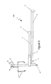
- FIG. 1 is a side view of a power lift and transfer system in accordance with an embodiment of the present disclosure in a bumper-mounted version with a wheelchair on the ground, fully deployed and adjacent to a door of a vehicle utilizing a suspended strap docking device as detailed in FIG. 5 .
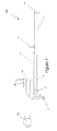
- FIG. 2 is a side view of a power lift and transfer system in accordance with an embodiment of the present disclosure in a bumper-mounted version with a wheelchair on the ground, fully deployed and adjacent to a door of a vehicle utilizing a latch and bolt docking device as detailed in FIG. 6 .
- FIG. 3 is a side view of a power lift and transfer system in accordance with an embodiment of the present disclosure in a bumper-mounted version with a wheelchair lifted and in a fully rearward position and with a canopy open.
- FIG. 4 is a side view of a power lift and transfer system in accordance with an embodiment of the present disclosure in a bumper-mounted version with a wheelchair lifted and in a fully rearward position and with a canopy closed.
- FIG. 5 is a detail view of a suspended strap style docking device referred to in FIG. 1 in accordance with an embodiment of the present disclosure.
- FIG. 6 is a detail view of a latch and bolt style docking device referred to in FIG. 2 in accordance with an embodiment of the present disclosure.
- FIG. 7 is a detail view of a blade style docking device in accordance with an embodiment of the present disclosure.
- FIG. 8 is a rear view of a power lift and transfer system in accordance with an embodiment of the present disclosure in a bumper-mounted version with a wheelchair in a fully stowed position.
- FIG. 9 is a rear view of a power lift and transfer system in accordance with an embodiment of the present disclosure in a hatch/trunk storage version with a wheelchair in a fully stowed position.
- FIG. 10 is a side view of a power lift and transfer system in accordance with an embodiment of the present disclosure in a hatch/trunk storage version with a wheelchair on the ground, fully deployed and adjacent to a door of a vehicle using a latch and bolt style docking device as detailed in FIG. 5 .
- FIG. 11 is a rear view of a power lift and transfer system in accordance with an embodiment of the present disclosure depicting a conveyor and support system to facilitate transfers of a user into a vehicle.
- FIG. 1 there is shown a power lift and transfer system 100 in accordance with an embodiment of the present disclosure in a bumper-mounted version with a wheelchair on the ground, fully deployed and adjacent to a door of a vehicle utilizing a suspended strap docking device as detailed in FIG. 5 .
- the system 100 includes a wheelchair 2 to be attached to a suspended strap docking device 3 .
- Docking device 3 comprises a strap which is spooled into a reel 4 which is attached to a shaft of a motor 5 , the housing of which is firmly attached to a vertical support 6 .
- the system 100 is a bumper-mounted version with a wheelchair on the ground, fully deployed and adjacent to a door of a vehicle utilizing a latch and bolt docking device as detailed in FIG. 6 .
- these figures are also representative of the operation and motion of the system 100 in the suspended strap ( FIG. 5 ) and blade ( FIG. 7 ) configurations.
- an electrical controller 26 which can control motors through encoders located within the motors or by means of limit switches located at various points during a stowage and deployment process.
- suspended strap docking device 3 may be raised or lowered, thus raising or lowering wheelchair 2 , which may be attached to suspended strap docking device 3 via hooks or other means of temporary connection in suspended strap docking device 3 .
- extension shaft 10 may be retracted into an extension shaft sleeve 11 driven by motor 12 , and an extension shaft 14 may be driven into an extension shaft sleeve 15 by a motor 16 .
- Smooth motion across the ground and proper weight support of system 100 may be provided by a wheel 13 as the wheelchair moves rearward.
- a pivoting motion about an axle 20 is induced, causing extension shafts 10 and 14 and extension shaft sleeves 15 and 11 to arrive at a substantially horizontal position.
- an actuator 28 propels a canopy 23 to a closed position and rotation of a horizontal support member 22 commences rotation about an axle 24 towards a rear of the vehicle powered by a motor 28 until it reaches a position approximately parallel with a rear face of the vehicle and perpendicular to a longitudinal axis of the vehicle as pictured in FIG. 8 .
- System 100 is at that point in a fully stowed position.
- the latch and bolt style docking device is shown in which the wheelchair 2 is fitted with a bolt plate 7 , the bolts of which are designed to be moved rearward into a “v” opening of a receiver 8 and latched to the receiver 8 by means of a pivoting motion of a latch 9 .
- the blade style docking device is shown in which the wheelchair 2 is fitted with a receiver plate 7 a which has a slot into which a blade 8 a fits as a receiver plate 7 moves rearward to induce a latching action.
- the blade 8 a incorporates a protrusion which when receiver plate 7 a moves rearward induces a pivoting motion of a latch 9 a and a positive latching connection between a slot in the latch 9 a and the protrusion.
- a “v” leading edge of the blade 8 a facilitates the user making a connection between the blade 8 a and the receiver plate 7 a.
- the system 100 is represented in an interior-mounted configuration which is similar to the hitch-mounted versions reflected in FIGS. 1-4 , with the exception that a mounting support 29 is located inside a cargo area or trunk of the vehicle.
- a horizontal support bar 18 when a horizontal support bar 18 reaches a fully stowed position, which may be substantially perpendicular to the longitudinal axis of the vehicle or, if space in an interior of the vehicle permits, may travel beyond that position to a position more parallel to a longitudinal axis of the vehicle.
- the wheelchair and system are fully inside the vehicle when in a fully stowed position.
- a conveyor and support system 200 in accordance with an embodiment of the present disclosure.
- the user may first deploy a transfer support 50 from a substantially vertical axis by pivoting the transfer support 50 about an axis of an axle 51 to a substantially horizontal position suitable for a level transfer from a wheelchair.
- the user may activate motor pairs 53 and 56 which in turn may cause a top surface of conveyor belts 54 and 55 to create an inward motion.
- the user may then transfer to a top of a conveyor belt 54 and be transported over the transfer support 50 and a seat of the vehicle 57 toward an interior of the vehicle.
- the user may stop the motors when in an appropriate position.
- system 200 may operate in a similar manner to that described above for the system 200 on the left side of FIG. 11 with the exception that conveyor belts 58 and 59 may be constructed in a continuous loop fashion and surround the seat 57 and the transfer support 50 in order to reduce a number of motors 56 as well as a complexity and cost of production of the system 200 .
Landscapes
- Health & Medical Sciences (AREA)
- Public Health (AREA)
- Life Sciences & Earth Sciences (AREA)
- Animal Behavior & Ethology (AREA)
- General Health & Medical Sciences (AREA)
- Veterinary Medicine (AREA)
- Nursing (AREA)
- Engineering & Computer Science (AREA)
- Mechanical Engineering (AREA)
- Handcart (AREA)
- Power-Operated Mechanisms For Wings (AREA)
- Vehicle Step Arrangements And Article Storage (AREA)
- Fittings On The Vehicle Exterior For Carrying Loads, And Devices For Holding Or Mounting Articles (AREA)
Abstract
Description
Claims (19)
Priority Applications (2)
| Application Number | Priority Date | Filing Date | Title |
|---|---|---|---|
| US12/461,029 US8540474B2 (en) | 2008-07-29 | 2009-07-29 | Power lift and transfer system and method |
| US13/998,002 US9526663B2 (en) | 2008-07-29 | 2013-09-23 | Power lift and transfer system and method |
Applications Claiming Priority (2)
| Application Number | Priority Date | Filing Date | Title |
|---|---|---|---|
| US12992208P | 2008-07-29 | 2008-07-29 | |
| US12/461,029 US8540474B2 (en) | 2008-07-29 | 2009-07-29 | Power lift and transfer system and method |
Related Child Applications (1)
| Application Number | Title | Priority Date | Filing Date |
|---|---|---|---|
| US13/998,002 Continuation US9526663B2 (en) | 2008-07-29 | 2013-09-23 | Power lift and transfer system and method |
Publications (2)
| Publication Number | Publication Date |
|---|---|
| US20100040452A1 US20100040452A1 (en) | 2010-02-18 |
| US8540474B2 true US8540474B2 (en) | 2013-09-24 |
Family
ID=41681371
Family Applications (2)
| Application Number | Title | Priority Date | Filing Date |
|---|---|---|---|
| US12/461,029 Active 2030-04-20 US8540474B2 (en) | 2008-07-29 | 2009-07-29 | Power lift and transfer system and method |
| US13/998,002 Active 2029-10-29 US9526663B2 (en) | 2008-07-29 | 2013-09-23 | Power lift and transfer system and method |
Family Applications After (1)
| Application Number | Title | Priority Date | Filing Date |
|---|---|---|---|
| US13/998,002 Active 2029-10-29 US9526663B2 (en) | 2008-07-29 | 2013-09-23 | Power lift and transfer system and method |
Country Status (1)
| Country | Link |
|---|---|
| US (2) | US8540474B2 (en) |
Cited By (5)
| Publication number | Priority date | Publication date | Assignee | Title |
|---|---|---|---|---|
| US20150044006A1 (en) * | 2012-03-19 | 2015-02-12 | Ricon Corp. | Installation method and arrangement for a wheelchair lift arrangment |
| US20150061316A1 (en) * | 2013-09-04 | 2015-03-05 | Tyrone Soklaski | Scooter lift canopy |
| CN105416192A (en) * | 2014-09-15 | 2016-03-23 | 福特全球技术公司 | Electrical bicycle modular powertrain |
| US20180085265A1 (en) * | 2016-09-23 | 2018-03-29 | Tim Arndorfer | Invalid lift device |
| US9937088B2 (en) * | 2015-04-30 | 2018-04-10 | Store-Easy, LLC | Automotive wheelchair storage device |
Families Citing this family (8)
| Publication number | Priority date | Publication date | Assignee | Title |
|---|---|---|---|---|
| US8540474B2 (en) | 2008-07-29 | 2013-09-24 | Thomas F. Egan | Power lift and transfer system and method |
| US9393885B2 (en) | 2010-08-05 | 2016-07-19 | Thomas F. Egan | Compact multi-motion lifting and transferring apparatus and method of operating same |
| US10028869B2 (en) | 2010-08-05 | 2018-07-24 | Thomas F. Egan | Power lift system and method |
| US10232792B2 (en) | 2011-02-03 | 2019-03-19 | Thomas F. Egan | Lifting and transferring apparatus and method |
| US9217535B1 (en) | 2013-02-21 | 2015-12-22 | Thomas F. Egan | Portable lifting and transferring techniques |
| DE102013014865A1 (en) * | 2013-09-05 | 2015-03-05 | Man Truck & Bus Ag | Vehicle case and associated method |
| US10052244B2 (en) * | 2015-12-31 | 2018-08-21 | Access-Able Designs, Inc. | Vehicle mounted extender apparatus |
| DE102017220196A1 (en) | 2017-11-14 | 2019-05-16 | Ford Global Technologies, Llc | Loading device, motor vehicle and mobility system |
Citations (101)
| Publication number | Priority date | Publication date | Assignee | Title |
|---|---|---|---|---|
| US360578A (en) | 1887-04-05 | Apparatus for handling grain in bags | ||
| US2792951A (en) | 1953-11-30 | 1957-05-21 | Charles E White | Invalid lift for automobiles |
| US3516559A (en) | 1968-02-15 | 1970-06-23 | Eldon G Walter | Wheelchair handling apparatus |
| US3710962A (en) | 1971-02-11 | 1973-01-16 | J Fowler | Lift device |
| US3715039A (en) * | 1969-12-16 | 1973-02-06 | Orenstein & Koppel Ag | Telescopic boom |
| US3896946A (en) | 1972-10-02 | 1975-07-29 | Robert W Forsyth | Transportation apparatus |
| US4015725A (en) | 1975-08-28 | 1977-04-05 | Marion County Muscular Dystrophy Foundation | Pivotable and extendable apparatus for lifting a person to and from a vehicle |
| US4075719A (en) | 1976-09-01 | 1978-02-28 | Sullivan Lawrence J | Chair lift apparatus |
| US4096955A (en) | 1976-09-10 | 1978-06-27 | Nolan Dake | Lifting mechanism |
| US4140230A (en) | 1977-05-12 | 1979-02-20 | Pearson Marvin R | Powered loading platform |
| US4169338A (en) * | 1976-09-03 | 1979-10-02 | A/S Normar | Telescopic boom |
| US4170368A (en) | 1976-11-22 | 1979-10-09 | Southward Engineering Co. Limited | Transportation of disabled or invalided persons |
| US4226567A (en) | 1978-06-09 | 1980-10-07 | D. W. Zimmerman Mfg., Inc. | Apparatus for handling bobbins |
| US4270630A (en) | 1977-11-28 | 1981-06-02 | Collins Industries, Inc. | Automatic lift assembly |
| US4298128A (en) * | 1980-02-19 | 1981-11-03 | Harnischfeger Corporation | Movable support for rotatable extend/retract screw in telescopic crane boom |
| US4306634A (en) | 1979-08-08 | 1981-12-22 | Sangster George G | Lift assembly |
| US4365924A (en) | 1980-08-01 | 1982-12-28 | Maurice C. Brigman | Disabled person transfer device |
| DE3123546A1 (en) | 1981-06-13 | 1983-01-27 | Emil Dautel GmbH u. Co KG, 7105 Leingarten | Wheelchair and goods lift for loading and unloading a vehicle |
| US4398858A (en) | 1980-10-31 | 1983-08-16 | Amigo Sales, Inc. | Apparatus for loading and unloading a secondary vehicle into and from an automobile |
| US4406574A (en) * | 1978-07-28 | 1983-09-27 | Riley Sidney L | Vehicle assist for disabled |
| US4420286A (en) | 1981-03-27 | 1983-12-13 | Wide One Corporation | Invalid lift apparatus |
| US4438640A (en) | 1980-12-04 | 1984-03-27 | Willis Robert E | Portable door brace |
| US4475861A (en) | 1982-11-15 | 1984-10-09 | Medansky Roland S | Automobile occupant hoist |
| US4483653A (en) | 1981-12-09 | 1984-11-20 | Brian Waite | Wheelchairs |
| US4545085A (en) | 1983-04-20 | 1985-10-08 | Landstingens Inkopscentral Lic | Wheeled structure for supporting a patient in a sitting position |
| US4551060A (en) | 1981-11-13 | 1985-11-05 | Societe Anonyme Des Usines Chausson | Device for raising various loads, particularly trolleys for handicapped persons, on vehicles |
| US4569094A (en) | 1983-10-24 | 1986-02-11 | Hart Lawrence D | Self-powered lift |
| US4573854A (en) | 1983-12-23 | 1986-03-04 | Mcfarland Robert E | Apparatus for loading a wheelchair or similar object |
| US4605132A (en) * | 1983-05-04 | 1986-08-12 | Seumeren Adelbert M D G Van | Lifting tool |
| US4616972A (en) | 1983-12-23 | 1986-10-14 | Mcfarland Robert E | Apparatus for loading a wheelchair or similar object |
| US4644595A (en) | 1985-10-29 | 1987-02-24 | Daniel R A | Portable motorized bed lift apparatus |
| US4659276A (en) * | 1984-09-17 | 1987-04-21 | Billett Trevor G | Load-handling apparatus for a vehicle |
| US4661035A (en) | 1982-08-25 | 1987-04-28 | Rolf Ahlbergs Mekaniska Verkstad Ab | Collapsible wheel-chair and apparatus for lifting the wheel-chair into and out from an automobile |
| US4664584A (en) | 1985-03-21 | 1987-05-12 | The Braun Corporation | Rotary wheelchair lift |
| US4671729A (en) | 1985-08-01 | 1987-06-09 | Mcfarland Robert E | Wheelchair loading apparatus |
| US4685860A (en) | 1983-12-23 | 1987-08-11 | Mcfarland Robert E | Apparatus for loading a wheelchair or similar object |
| US4786072A (en) | 1987-06-15 | 1988-11-22 | K G Engineering, Inc. | Collapsible wheelchair and lift assembly |
| US4797042A (en) | 1985-08-01 | 1989-01-10 | Mcfarland Robert E | Wheelchair loading apparatus |
| US4801237A (en) | 1985-09-03 | 1989-01-31 | Nissan Motor Co., Ltd. | Transportation device for commercial and industrial use |
| US4808056A (en) | 1987-08-18 | 1989-02-28 | Shinnosuke Oshima | Elevator device transportable in a motor vehicle |
| US4809998A (en) | 1987-06-15 | 1989-03-07 | K G Engineering, Inc. | Collapsible wheelchair and lift assembly |
| SU1484678A1 (en) | 1987-09-24 | 1989-06-07 | Volzh Ob Proizv | Manipulator |
| US4955779A (en) | 1986-10-28 | 1990-09-11 | Jaromir Vaclav Drazil | Connector |
| US4974766A (en) * | 1988-12-21 | 1990-12-04 | Sportstore Systems, Inc. | Vehicle roof top carrier and method of using same |
| US5022106A (en) | 1988-10-08 | 1991-06-11 | Arjo Mecanaids Limited | Invalid hoists |
| US5035467A (en) | 1988-09-15 | 1991-07-30 | Pin Dot Products | Seating system |
| US5040832A (en) | 1990-03-07 | 1991-08-20 | Enhancement Unlimited, Inc. | Automobile seat for disabled persons |
| US5102195A (en) | 1988-09-15 | 1992-04-07 | Pin Dot Products | Seating system |
| US5154563A (en) | 1990-07-12 | 1992-10-13 | Phillips J Rodney | Wheel chair carrier |
| US5160236A (en) | 1991-07-31 | 1992-11-03 | Redding Edward M | Retractable van side door ramp |
| US5180275A (en) | 1991-05-28 | 1993-01-19 | The Braun Corporation | Rotary bus lift with power stowable platform |
| US5193633A (en) | 1991-06-07 | 1993-03-16 | Wright State University | Motorized transfer and transport system for the disabled |
| US5201377A (en) | 1990-02-23 | 1993-04-13 | Love Lift, L.P. | Wheelchair with sidewardly swingable seat |
| US5205697A (en) | 1991-04-19 | 1993-04-27 | Wollard Airport Equipment Company | Mobile passenger access lift |
| US5261779A (en) | 1992-01-24 | 1993-11-16 | The Braun Corporation | Dual hydraulic, parallelogram arm wheelchair lift |
| US5308214A (en) | 1993-03-08 | 1994-05-03 | Chrysler Corporation | Wheelchair lift apparatus |
| US5333333A (en) | 1993-01-06 | 1994-08-02 | Mah Gordon B J | Transportation, sanitation and therapy system for handicapped people |
| US5348172A (en) | 1993-03-02 | 1994-09-20 | Wilson Frederick F K | Industrial carrying machine |
| US5375913A (en) | 1993-03-19 | 1994-12-27 | Blanchard; James E. | Lift device for wheelchairs |
| US5431526A (en) | 1992-07-06 | 1995-07-11 | Peterson; Edward A. | Lifting system for transporting vehicle |
| US5456335A (en) | 1994-08-18 | 1995-10-10 | Kinsey; James E. | Patient lifting device |
| US5456568A (en) | 1993-12-27 | 1995-10-10 | Kirby; Jeffrey R. | Arm mechanism |
| US5459891A (en) | 1993-08-24 | 1995-10-24 | Reeve; Richard J. | Invalid lift and transport apparatus |
| US5467813A (en) | 1991-03-27 | 1995-11-21 | Vermaat Technics B.V. | Robot with suction cup attachment to steam generator partition |
| US5502851A (en) | 1994-05-26 | 1996-04-02 | Costello; Martin D. | Assisted lifting, stand and walking device |
| US5520403A (en) * | 1995-03-28 | 1996-05-28 | Bergstrom; Michele R. | Wheelchair with translating seat and patient lift |
| US5540539A (en) | 1995-01-09 | 1996-07-30 | Wolfman; Paul R. | Transfer apparatus for moving a person from a wheelchair into an automobile |
| US5542811A (en) | 1995-01-04 | 1996-08-06 | Vartanian; Roger | Wheelchair lift with laterally displaceable support post for vertical and rotational displacement |
| US5560054A (en) | 1994-08-16 | 1996-10-01 | William H. Simon | Storable patient lift and transfer apparatus |
| US5617963A (en) | 1995-06-14 | 1997-04-08 | Unique Concepts Inc. | Apparatus for mounting an appliance at an opening |
| US5639105A (en) | 1995-05-30 | 1997-06-17 | Michael W. Summo | Occupant propelled apparatus for therapy, exercise and mobility-particularly for children |
| US5649329A (en) | 1994-12-06 | 1997-07-22 | Horcher Gmbh | Device for lifting and/or transporting of a person, in particular a patient lifter |
| US5746563A (en) | 1992-04-02 | 1998-05-05 | Steckler; Dov | Car and a device for inserting and taking out a wheel chair from a luggage compartment |
| GB2322352A (en) * | 1997-02-19 | 1998-08-26 | David Leslie Walker | Wheelchair stowage apparatus |
| US5827036A (en) * | 1996-03-28 | 1998-10-27 | Tip Top Mobility, Inc. | Wheelchair lift |
| US5845348A (en) | 1994-05-10 | 1998-12-08 | Arjo Limited | Invalid hoist |
| US5857832A (en) | 1997-09-24 | 1999-01-12 | Bloorview Macmillan Centre | Restraint seat and hoist |
| JPH11253492A (en) | 1998-03-10 | 1999-09-21 | Toyota Max:Kk | Wheelchair seat transfer device |
| US5987664A (en) | 1997-08-08 | 1999-11-23 | Arjo Limited | Invalid hoists |
| US6026523A (en) | 1998-10-14 | 2000-02-22 | Simon; William H. | Storable patient lift and transfer apparatus |
| US6039402A (en) * | 1999-02-12 | 2000-03-21 | Tachi-S Co., Ltd. | Seat provided with a seat climbing/descending aid structure for easy climbing onto and descending from the seat, and a seat climbing/descending aid designed for that purpose |
| US6042330A (en) | 1996-08-29 | 2000-03-28 | Egan; Thomas F. | Electrically actuated lifting and transferring apparatus |
| US6223364B1 (en) | 1998-07-09 | 2001-05-01 | Thomas F. Egan | Multi-motion lifting and transferring apparatus and method |
| US6260218B1 (en) | 1998-11-04 | 2001-07-17 | Mechatec Co., Ltd. | Traveling lift |
| US6283528B1 (en) | 1999-07-21 | 2001-09-04 | Steven J. Townsend | Folding motor vehicle entry seat for persons who use wheelchairs and others who have physical limitations |
| US6289534B1 (en) | 1998-07-31 | 2001-09-18 | Hill-Rom Services, Inc. | Patient lift |
| JP2001315565A (en) | 2000-03-01 | 2001-11-13 | Tadanori Matsuda | Vehicular lift |
| US6367103B1 (en) | 1999-10-19 | 2002-04-09 | Arjo Limited | Invalid hoists |
| US6595738B2 (en) | 1999-09-30 | 2003-07-22 | Waltco Truck Equipment | Side door lift gate |
| US6612802B2 (en) | 2000-08-04 | 2003-09-02 | Thomas F. Egan | Electrically-actuated transfer seat |
| US6682291B2 (en) * | 2000-11-10 | 2004-01-27 | Webasto Vehicle Systems International Gmbh | Transport device for loading and unloading a trunk space |
| US6739642B1 (en) | 2002-01-29 | 2004-05-25 | Thomas F. Egan | Electrically actuated lifting and transferring apparatus |
| JP2004195062A (en) | 2002-12-20 | 2004-07-15 | Jinya Matsuda | Loading/unloading device in vehicle |
| US6823541B2 (en) | 2000-08-04 | 2004-11-30 | Thomas F. Egan | Portable support apparatus and method |
| US20060045686A1 (en) * | 2004-07-14 | 2006-03-02 | Krichevsky Alexander | Mechanism for insertion of a wheelchair into a car |
| US20060182569A1 (en) * | 2002-10-04 | 2006-08-17 | Andersson Charlotte S | Device at a box for a car |
| US7207765B1 (en) | 2003-08-29 | 2007-04-24 | Egan Thomas F | Electrically-actuated transfer seat |
| US7284944B1 (en) | 2003-11-24 | 2007-10-23 | Schlangen Phillip E | Lift and transport apparatus |
| US7383107B2 (en) | 2002-07-02 | 2008-06-03 | The United States Of America As Represented By The Department Of Veterans Affairs | Computer-controlled power wheelchair navigation system |
| US7404505B2 (en) * | 2004-08-06 | 2008-07-29 | William P. Walther | Driver accessible wheelchair carrier |
| US7543876B1 (en) | 2004-05-11 | 2009-06-09 | Egan Thomas F | Electrically actuated lifting and transferring apparatus |
Family Cites Families (47)
| Publication number | Priority date | Publication date | Assignee | Title |
|---|---|---|---|---|
| US1465168A (en) * | 1921-12-03 | 1923-08-14 | Morris Fred Monroe | Hitch |
| US2636744A (en) * | 1949-06-04 | 1953-04-28 | Leonard E Trees | Tractor hitch |
| US2864431A (en) | 1956-04-20 | 1958-12-16 | Howard L Eaton | Swing-out elevating seat for automobiles |
| US3147994A (en) | 1961-04-18 | 1964-09-08 | Gen Motors Corp | Swing-out vehicle seat |
| US3891237A (en) * | 1974-03-29 | 1975-06-24 | Bill Allen | Trailer hitch |
| DE2712705C3 (en) * | 1977-03-23 | 1980-01-03 | Ingenieurgesellschaft Kuhbier Kg, 4044 Kaarst | Transport, transfer and storage system for means of payment, valuables or other valuable or dangerous substances |
| US4133437A (en) | 1977-09-09 | 1979-01-09 | Helper Industries, Inc. | Wheel chair lift apparatus |
| US4225149A (en) * | 1979-03-28 | 1980-09-30 | Koopman Robert J | Remotely operable trailer hitch |
| DE3164267D1 (en) * | 1980-03-19 | 1984-07-26 | Gowrings Ltd | A motor vehicle having a vehicle entry system for invalids |
| US4458870A (en) | 1981-04-17 | 1984-07-10 | Duncan Leroy R | Adjustable support attachment for wheelchairs |
| US4479753A (en) | 1982-05-19 | 1984-10-30 | Transportation Design & Technology, Inc. | Wheelchair lift for passenger vehicles |
| US4463965A (en) * | 1982-09-29 | 1984-08-07 | Lawson Floyd A | Trailer mounted boat retainer device |
| US4566842A (en) * | 1984-04-30 | 1986-01-28 | Autodynamics Corporation Of America | Wheelchair dockage and storage system |
| US4793626A (en) * | 1987-04-17 | 1988-12-27 | Gefroh John A | Trailer hitch |
| FR2620492B1 (en) * | 1987-09-11 | 1990-01-12 | Aerospatiale | SYSTEM FOR COUPLING TWO BODIES FOR EXAMPLE A TROLLEY AND A MACHINING STATION |
| US4844497A (en) * | 1988-06-06 | 1989-07-04 | Bill Allen | Self-coupling trailer hitch |
| US5149246A (en) | 1990-05-17 | 1992-09-22 | Stewart & Stevenson Power, Inc. | Wheelchair lift apparatus for commercial vehicles |
| CA2077879C (en) * | 1992-08-11 | 1997-07-01 | David G. Ullman | Securement system for a rollable mobility aid |
| US5630638A (en) | 1994-10-19 | 1997-05-20 | Wako Kogyo Kabushiki Kaisha | Seat lift mechanism for an automotive vehicle |
| US5628595A (en) * | 1995-03-22 | 1997-05-13 | Associated Partnership Ltd. Inc. | Wheelchair lock-down device |
| US6086085A (en) * | 1998-01-15 | 2000-07-11 | Larsson; Walter | Combination of a car-seat and a wheel chair |
| US6238169B1 (en) | 1998-05-01 | 2001-05-29 | The Braun Corporation | Dual function inboard barrier/bridgeplate assembly for wheelchair lifts |
| US6416272B1 (en) * | 1998-10-09 | 2002-07-09 | Toyota Shatai Kabushiki Kaisha | Wheelchair with retractable wheels for conversion to vehicle passenger seat |
| US6296221B1 (en) | 1998-11-05 | 2001-10-02 | Jacques Nadeau | Universal seat suspension system |
| US6086312A (en) | 1999-03-17 | 2000-07-11 | Ziaylek; Michael P. | Tank handling apparatus |
| CA2279170A1 (en) * | 1999-07-30 | 2001-01-30 | Donald A. Logan | Wheelchair system |
| US6390554B1 (en) | 1999-11-23 | 2002-05-21 | 1239907 Ontario Limited | Weight positioning reclining seat kit for wheelchairs |
| US6526677B1 (en) * | 2000-10-06 | 2003-03-04 | Douglas Dynamics, L.L.C. | Snowplow mounting assembly |
| US6692215B1 (en) | 2001-03-26 | 2004-02-17 | Cook Technologies, Inc. | Lift and carrier assembly for a personal-transport vehicle |
| US7374390B2 (en) * | 2001-05-25 | 2008-05-20 | Integrated Vision, Inc. | Lift mechanism for a seating device |
| AUPR798001A0 (en) * | 2001-09-27 | 2001-10-25 | Baribunma Holdings Pty Limited | Adjustable wheelchair |
| US6612615B1 (en) | 2001-09-28 | 2003-09-02 | Eldad Dimand | Trailer hitch cart attachment mechanism |
| US6729829B2 (en) * | 2001-12-07 | 2004-05-04 | Sherrod Vans Of Jacksonville, Inc. | Wheelchair vehicle access system |
| JP2003285673A (en) | 2002-03-29 | 2003-10-07 | Honda Motor Co Ltd | Rear seat attitude change device for vehicles |
| CN100377916C (en) | 2002-08-12 | 2008-04-02 | 丰田车体株式会社 | Vehicle seat moving device |
| JP4152716B2 (en) * | 2002-10-15 | 2008-09-17 | スガツネ工業株式会社 | Stay |
| US6928766B1 (en) * | 2002-10-23 | 2005-08-16 | Pipe Welders, Inc. | Automatic outrigger lock |
| WO2004106126A2 (en) * | 2003-05-27 | 2004-12-09 | Cook Technologies, Inc. | Device for securing a personal-transport vehicle to a mounting surface |
| US7011330B2 (en) * | 2003-07-03 | 2006-03-14 | Toyota Motor Manufacturing North America, Inc. | Automatic hitch assembly |
| GB2408928B (en) | 2003-12-10 | 2006-05-17 | Lear Corp | Vehicle seat track with hydraulic actuator |
| US7621365B2 (en) | 2004-02-26 | 2009-11-24 | Egan Thomas F | Technique for controlling vehicle functions |
| US7862287B2 (en) | 2004-04-13 | 2011-01-04 | Egan Thomas F | Multi-motion lifting and transferring apparatus and method |
| US20060087166A1 (en) | 2004-10-22 | 2006-04-27 | Sunrise Medical Hhg Inc. | Power lift and tilt modules |
| US7717663B1 (en) | 2005-04-28 | 2010-05-18 | Creative Controls, Inc. | Lift mechanism for utility vehicles |
| US8132997B2 (en) | 2007-02-14 | 2012-03-13 | Razor Products, Inc. | Lift apparatus mountable on a vehicle |
| US8540474B2 (en) | 2008-07-29 | 2013-09-24 | Thomas F. Egan | Power lift and transfer system and method |
| US9393885B2 (en) | 2010-08-05 | 2016-07-19 | Thomas F. Egan | Compact multi-motion lifting and transferring apparatus and method of operating same |
-
2009
- 2009-07-29 US US12/461,029 patent/US8540474B2/en active Active
-
2013
- 2013-09-23 US US13/998,002 patent/US9526663B2/en active Active
Patent Citations (105)
| Publication number | Priority date | Publication date | Assignee | Title |
|---|---|---|---|---|
| US360578A (en) | 1887-04-05 | Apparatus for handling grain in bags | ||
| US2792951A (en) | 1953-11-30 | 1957-05-21 | Charles E White | Invalid lift for automobiles |
| US3516559A (en) | 1968-02-15 | 1970-06-23 | Eldon G Walter | Wheelchair handling apparatus |
| US3715039A (en) * | 1969-12-16 | 1973-02-06 | Orenstein & Koppel Ag | Telescopic boom |
| US3710962A (en) | 1971-02-11 | 1973-01-16 | J Fowler | Lift device |
| US3896946A (en) | 1972-10-02 | 1975-07-29 | Robert W Forsyth | Transportation apparatus |
| US4015725A (en) | 1975-08-28 | 1977-04-05 | Marion County Muscular Dystrophy Foundation | Pivotable and extendable apparatus for lifting a person to and from a vehicle |
| US4075719A (en) | 1976-09-01 | 1978-02-28 | Sullivan Lawrence J | Chair lift apparatus |
| US4169338A (en) * | 1976-09-03 | 1979-10-02 | A/S Normar | Telescopic boom |
| US4096955A (en) | 1976-09-10 | 1978-06-27 | Nolan Dake | Lifting mechanism |
| US4142641A (en) | 1976-09-10 | 1979-03-06 | Nolan Dake | Transfer mechanism |
| US4170368A (en) | 1976-11-22 | 1979-10-09 | Southward Engineering Co. Limited | Transportation of disabled or invalided persons |
| US4140230A (en) | 1977-05-12 | 1979-02-20 | Pearson Marvin R | Powered loading platform |
| US4270630A (en) | 1977-11-28 | 1981-06-02 | Collins Industries, Inc. | Automatic lift assembly |
| US4226567A (en) | 1978-06-09 | 1980-10-07 | D. W. Zimmerman Mfg., Inc. | Apparatus for handling bobbins |
| US4406574A (en) * | 1978-07-28 | 1983-09-27 | Riley Sidney L | Vehicle assist for disabled |
| US4306634A (en) | 1979-08-08 | 1981-12-22 | Sangster George G | Lift assembly |
| US4298128A (en) * | 1980-02-19 | 1981-11-03 | Harnischfeger Corporation | Movable support for rotatable extend/retract screw in telescopic crane boom |
| US4365924A (en) | 1980-08-01 | 1982-12-28 | Maurice C. Brigman | Disabled person transfer device |
| US4398858A (en) | 1980-10-31 | 1983-08-16 | Amigo Sales, Inc. | Apparatus for loading and unloading a secondary vehicle into and from an automobile |
| US4438640A (en) | 1980-12-04 | 1984-03-27 | Willis Robert E | Portable door brace |
| US4420286A (en) | 1981-03-27 | 1983-12-13 | Wide One Corporation | Invalid lift apparatus |
| DE3123546A1 (en) | 1981-06-13 | 1983-01-27 | Emil Dautel GmbH u. Co KG, 7105 Leingarten | Wheelchair and goods lift for loading and unloading a vehicle |
| US4551060A (en) | 1981-11-13 | 1985-11-05 | Societe Anonyme Des Usines Chausson | Device for raising various loads, particularly trolleys for handicapped persons, on vehicles |
| US4483653A (en) | 1981-12-09 | 1984-11-20 | Brian Waite | Wheelchairs |
| US4661035A (en) | 1982-08-25 | 1987-04-28 | Rolf Ahlbergs Mekaniska Verkstad Ab | Collapsible wheel-chair and apparatus for lifting the wheel-chair into and out from an automobile |
| US4475861A (en) | 1982-11-15 | 1984-10-09 | Medansky Roland S | Automobile occupant hoist |
| US4545085A (en) | 1983-04-20 | 1985-10-08 | Landstingens Inkopscentral Lic | Wheeled structure for supporting a patient in a sitting position |
| US4605132A (en) * | 1983-05-04 | 1986-08-12 | Seumeren Adelbert M D G Van | Lifting tool |
| US4569094A (en) | 1983-10-24 | 1986-02-11 | Hart Lawrence D | Self-powered lift |
| US4616972A (en) | 1983-12-23 | 1986-10-14 | Mcfarland Robert E | Apparatus for loading a wheelchair or similar object |
| US4573854A (en) | 1983-12-23 | 1986-03-04 | Mcfarland Robert E | Apparatus for loading a wheelchair or similar object |
| US4685860A (en) | 1983-12-23 | 1987-08-11 | Mcfarland Robert E | Apparatus for loading a wheelchair or similar object |
| US4659276A (en) * | 1984-09-17 | 1987-04-21 | Billett Trevor G | Load-handling apparatus for a vehicle |
| US4664584A (en) | 1985-03-21 | 1987-05-12 | The Braun Corporation | Rotary wheelchair lift |
| US4797042A (en) | 1985-08-01 | 1989-01-10 | Mcfarland Robert E | Wheelchair loading apparatus |
| US4671729A (en) | 1985-08-01 | 1987-06-09 | Mcfarland Robert E | Wheelchair loading apparatus |
| US4801237A (en) | 1985-09-03 | 1989-01-31 | Nissan Motor Co., Ltd. | Transportation device for commercial and industrial use |
| US4644595A (en) | 1985-10-29 | 1987-02-24 | Daniel R A | Portable motorized bed lift apparatus |
| US4955779A (en) | 1986-10-28 | 1990-09-11 | Jaromir Vaclav Drazil | Connector |
| US4786072A (en) | 1987-06-15 | 1988-11-22 | K G Engineering, Inc. | Collapsible wheelchair and lift assembly |
| US4809998A (en) | 1987-06-15 | 1989-03-07 | K G Engineering, Inc. | Collapsible wheelchair and lift assembly |
| US4808056A (en) | 1987-08-18 | 1989-02-28 | Shinnosuke Oshima | Elevator device transportable in a motor vehicle |
| SU1484678A1 (en) | 1987-09-24 | 1989-06-07 | Volzh Ob Proizv | Manipulator |
| US5035467A (en) | 1988-09-15 | 1991-07-30 | Pin Dot Products | Seating system |
| US5102195A (en) | 1988-09-15 | 1992-04-07 | Pin Dot Products | Seating system |
| US5022106A (en) | 1988-10-08 | 1991-06-11 | Arjo Mecanaids Limited | Invalid hoists |
| US4974766A (en) * | 1988-12-21 | 1990-12-04 | Sportstore Systems, Inc. | Vehicle roof top carrier and method of using same |
| US5201377A (en) | 1990-02-23 | 1993-04-13 | Love Lift, L.P. | Wheelchair with sidewardly swingable seat |
| US5040832A (en) | 1990-03-07 | 1991-08-20 | Enhancement Unlimited, Inc. | Automobile seat for disabled persons |
| US5154563A (en) | 1990-07-12 | 1992-10-13 | Phillips J Rodney | Wheel chair carrier |
| US5467813A (en) | 1991-03-27 | 1995-11-21 | Vermaat Technics B.V. | Robot with suction cup attachment to steam generator partition |
| US5205697A (en) | 1991-04-19 | 1993-04-27 | Wollard Airport Equipment Company | Mobile passenger access lift |
| US5180275A (en) | 1991-05-28 | 1993-01-19 | The Braun Corporation | Rotary bus lift with power stowable platform |
| US5193633A (en) | 1991-06-07 | 1993-03-16 | Wright State University | Motorized transfer and transport system for the disabled |
| US5160236A (en) | 1991-07-31 | 1992-11-03 | Redding Edward M | Retractable van side door ramp |
| US5261779A (en) | 1992-01-24 | 1993-11-16 | The Braun Corporation | Dual hydraulic, parallelogram arm wheelchair lift |
| US5746563A (en) | 1992-04-02 | 1998-05-05 | Steckler; Dov | Car and a device for inserting and taking out a wheel chair from a luggage compartment |
| US5431526A (en) | 1992-07-06 | 1995-07-11 | Peterson; Edward A. | Lifting system for transporting vehicle |
| US5333333A (en) | 1993-01-06 | 1994-08-02 | Mah Gordon B J | Transportation, sanitation and therapy system for handicapped people |
| US5348172A (en) | 1993-03-02 | 1994-09-20 | Wilson Frederick F K | Industrial carrying machine |
| US5308214A (en) | 1993-03-08 | 1994-05-03 | Chrysler Corporation | Wheelchair lift apparatus |
| US5375913A (en) | 1993-03-19 | 1994-12-27 | Blanchard; James E. | Lift device for wheelchairs |
| US5459891A (en) | 1993-08-24 | 1995-10-24 | Reeve; Richard J. | Invalid lift and transport apparatus |
| US5456568A (en) | 1993-12-27 | 1995-10-10 | Kirby; Jeffrey R. | Arm mechanism |
| US5845348A (en) | 1994-05-10 | 1998-12-08 | Arjo Limited | Invalid hoist |
| US5502851A (en) | 1994-05-26 | 1996-04-02 | Costello; Martin D. | Assisted lifting, stand and walking device |
| US5682630A (en) | 1994-08-16 | 1997-11-04 | Simon; William H. | Storable patient lift and transfer apparatus |
| US5560054A (en) | 1994-08-16 | 1996-10-01 | William H. Simon | Storable patient lift and transfer apparatus |
| US5456335A (en) | 1994-08-18 | 1995-10-10 | Kinsey; James E. | Patient lifting device |
| US5649329A (en) | 1994-12-06 | 1997-07-22 | Horcher Gmbh | Device for lifting and/or transporting of a person, in particular a patient lifter |
| US5542811A (en) | 1995-01-04 | 1996-08-06 | Vartanian; Roger | Wheelchair lift with laterally displaceable support post for vertical and rotational displacement |
| US5540539A (en) | 1995-01-09 | 1996-07-30 | Wolfman; Paul R. | Transfer apparatus for moving a person from a wheelchair into an automobile |
| US5520403A (en) * | 1995-03-28 | 1996-05-28 | Bergstrom; Michele R. | Wheelchair with translating seat and patient lift |
| US5639105A (en) | 1995-05-30 | 1997-06-17 | Michael W. Summo | Occupant propelled apparatus for therapy, exercise and mobility-particularly for children |
| US5617963A (en) | 1995-06-14 | 1997-04-08 | Unique Concepts Inc. | Apparatus for mounting an appliance at an opening |
| US5827036A (en) * | 1996-03-28 | 1998-10-27 | Tip Top Mobility, Inc. | Wheelchair lift |
| US6042330A (en) | 1996-08-29 | 2000-03-28 | Egan; Thomas F. | Electrically actuated lifting and transferring apparatus |
| GB2322352A (en) * | 1997-02-19 | 1998-08-26 | David Leslie Walker | Wheelchair stowage apparatus |
| US5987664A (en) | 1997-08-08 | 1999-11-23 | Arjo Limited | Invalid hoists |
| US5857832A (en) | 1997-09-24 | 1999-01-12 | Bloorview Macmillan Centre | Restraint seat and hoist |
| JPH11253492A (en) | 1998-03-10 | 1999-09-21 | Toyota Max:Kk | Wheelchair seat transfer device |
| US6223364B1 (en) | 1998-07-09 | 2001-05-01 | Thomas F. Egan | Multi-motion lifting and transferring apparatus and method |
| US6289534B1 (en) | 1998-07-31 | 2001-09-18 | Hill-Rom Services, Inc. | Patient lift |
| US6026523A (en) | 1998-10-14 | 2000-02-22 | Simon; William H. | Storable patient lift and transfer apparatus |
| US6260218B1 (en) | 1998-11-04 | 2001-07-17 | Mechatec Co., Ltd. | Traveling lift |
| US6039402A (en) * | 1999-02-12 | 2000-03-21 | Tachi-S Co., Ltd. | Seat provided with a seat climbing/descending aid structure for easy climbing onto and descending from the seat, and a seat climbing/descending aid designed for that purpose |
| US6283528B1 (en) | 1999-07-21 | 2001-09-04 | Steven J. Townsend | Folding motor vehicle entry seat for persons who use wheelchairs and others who have physical limitations |
| US6595738B2 (en) | 1999-09-30 | 2003-07-22 | Waltco Truck Equipment | Side door lift gate |
| US6367103B1 (en) | 1999-10-19 | 2002-04-09 | Arjo Limited | Invalid hoists |
| JP2001315565A (en) | 2000-03-01 | 2001-11-13 | Tadanori Matsuda | Vehicular lift |
| US6823541B2 (en) | 2000-08-04 | 2004-11-30 | Thomas F. Egan | Portable support apparatus and method |
| US6612802B2 (en) | 2000-08-04 | 2003-09-02 | Thomas F. Egan | Electrically-actuated transfer seat |
| US7651313B1 (en) | 2000-08-04 | 2010-01-26 | Egan Thomas F | Electrically-actuated transfer seat |
| US6682291B2 (en) * | 2000-11-10 | 2004-01-27 | Webasto Vehicle Systems International Gmbh | Transport device for loading and unloading a trunk space |
| US6739642B1 (en) | 2002-01-29 | 2004-05-25 | Thomas F. Egan | Electrically actuated lifting and transferring apparatus |
| US7383107B2 (en) | 2002-07-02 | 2008-06-03 | The United States Of America As Represented By The Department Of Veterans Affairs | Computer-controlled power wheelchair navigation system |
| US20060182569A1 (en) * | 2002-10-04 | 2006-08-17 | Andersson Charlotte S | Device at a box for a car |
| JP2004195062A (en) | 2002-12-20 | 2004-07-15 | Jinya Matsuda | Loading/unloading device in vehicle |
| US7207765B1 (en) | 2003-08-29 | 2007-04-24 | Egan Thomas F | Electrically-actuated transfer seat |
| US7284944B1 (en) | 2003-11-24 | 2007-10-23 | Schlangen Phillip E | Lift and transport apparatus |
| US7543876B1 (en) | 2004-05-11 | 2009-06-09 | Egan Thomas F | Electrically actuated lifting and transferring apparatus |
| US20060045686A1 (en) * | 2004-07-14 | 2006-03-02 | Krichevsky Alexander | Mechanism for insertion of a wheelchair into a car |
| US7402019B2 (en) * | 2004-07-14 | 2008-07-22 | Krichevsky Alexander | Mechanism for insertion of a wheelchair into a car |
| US7404505B2 (en) * | 2004-08-06 | 2008-07-29 | William P. Walther | Driver accessible wheelchair carrier |
Cited By (7)
| Publication number | Priority date | Publication date | Assignee | Title |
|---|---|---|---|---|
| US20150044006A1 (en) * | 2012-03-19 | 2015-02-12 | Ricon Corp. | Installation method and arrangement for a wheelchair lift arrangment |
| US9943454B2 (en) * | 2012-03-19 | 2018-04-17 | Ricon Corp. | Installation method and arrangement for a wheelchair lift arrangement |
| US20150061316A1 (en) * | 2013-09-04 | 2015-03-05 | Tyrone Soklaski | Scooter lift canopy |
| US9403473B2 (en) * | 2013-09-04 | 2016-08-02 | Tyrone Soklaski | Scooter lift canopy |
| CN105416192A (en) * | 2014-09-15 | 2016-03-23 | 福特全球技术公司 | Electrical bicycle modular powertrain |
| US9937088B2 (en) * | 2015-04-30 | 2018-04-10 | Store-Easy, LLC | Automotive wheelchair storage device |
| US20180085265A1 (en) * | 2016-09-23 | 2018-03-29 | Tim Arndorfer | Invalid lift device |
Also Published As
| Publication number | Publication date |
|---|---|
| US9526663B2 (en) | 2016-12-27 |
| US20100040452A1 (en) | 2010-02-18 |
| US20150086311A1 (en) | 2015-03-26 |
| US20160184149A9 (en) | 2016-06-30 |
Similar Documents
| Publication | Publication Date | Title |
|---|---|---|
| US8540474B2 (en) | Power lift and transfer system and method | |
| US6729829B2 (en) | Wheelchair vehicle access system | |
| US6616396B2 (en) | Power ramp for personal mobility vehicles and method of use | |
| EP1813455A2 (en) | Vehicle with an entrance aid | |
| US7296960B2 (en) | Coupling system for attachment of a seat to allow securing and/or lifting thereof | |
| US9393885B2 (en) | Compact multi-motion lifting and transferring apparatus and method of operating same | |
| US12414883B2 (en) | Manually foldable wheelchair ramp | |
| AU753286B2 (en) | Automobile ingress/egress system | |
| US20120013102A1 (en) | Sliding Seat for Wheelchair Occupant to Enter and Exit Motor Vehicles | |
| GB2116940A (en) | Collapsible ramp | |
| JP2022532571A (en) | Methods and equipment to releasably secure the robot to the delivery vehicle | |
| US7374390B2 (en) | Lift mechanism for a seating device | |
| WO2009140714A9 (en) | Vehicle mounted, wheelchair boarding apparatus | |
| US10028869B2 (en) | Power lift system and method | |
| US4541511A (en) | Wheelchair elevator and docking system | |
| US11358509B2 (en) | Automated cargo vehicle ramp deployment system and associated methods | |
| CN109774611A (en) | Lifting devices for wheelchairs, and motor vehicles | |
| JPH0134176B2 (en) | ||
| US20080025829A1 (en) | Highway Vehicle for Handicapped Drivers in Mobility | |
| RU217545U1 (en) | Car for people with disabilities and people with limited mobility | |
| WO2024243588A1 (en) | Articulating seating system with integrated lifting device | |
| EP2083783A2 (en) | Wheel chair and transport system for the same | |
| CZ34657U1 (en) | Integrated airborne module for cars to transport disabled people | |
| KR20240131707A (en) | Disabled vehicles with wheelchair boarding plates | |
| AU2006235966A1 (en) | Personnel hoist |
Legal Events
| Date | Code | Title | Description |
|---|---|---|---|
| STCF | Information on status: patent grant |
Free format text: PATENTED CASE |
|
| FPAY | Fee payment |
Year of fee payment: 4 |
|
| FEPP | Fee payment procedure |
Free format text: MAINTENANCE FEE REMINDER MAILED (ORIGINAL EVENT CODE: REM.); ENTITY STATUS OF PATENT OWNER: SMALL ENTITY |
|
| FEPP | Fee payment procedure |
Free format text: 7.5 YR SURCHARGE - LATE PMT W/IN 6 MO, SMALL ENTITY (ORIGINAL EVENT CODE: M2555); ENTITY STATUS OF PATENT OWNER: SMALL ENTITY |
|
| MAFP | Maintenance fee payment |
Free format text: PAYMENT OF MAINTENANCE FEE, 8TH YR, SMALL ENTITY (ORIGINAL EVENT CODE: M2552); ENTITY STATUS OF PATENT OWNER: SMALL ENTITY Year of fee payment: 8 |
|
| MAFP | Maintenance fee payment |
Free format text: PAYMENT OF MAINTENANCE FEE, 12TH YR, SMALL ENTITY (ORIGINAL EVENT CODE: M2553); ENTITY STATUS OF PATENT OWNER: SMALL ENTITY Year of fee payment: 12 |