US8527174B2 - Brake controlling apparatus - Google Patents
Brake controlling apparatus Download PDFInfo
- Publication number
- US8527174B2 US8527174B2 US13/124,804 US200813124804A US8527174B2 US 8527174 B2 US8527174 B2 US 8527174B2 US 200813124804 A US200813124804 A US 200813124804A US 8527174 B2 US8527174 B2 US 8527174B2
- Authority
- US
- United States
- Prior art keywords
- brake
- brake liquid
- pressure
- booster valve
- liquid pressure
- Prior art date
- Legal status (The legal status is an assumption and is not a legal conclusion. Google has not performed a legal analysis and makes no representation as to the accuracy of the status listed.)
- Active, expires
Links
Images


Classifications
-
- B—PERFORMING OPERATIONS; TRANSPORTING
- B60—VEHICLES IN GENERAL
- B60T—VEHICLE BRAKE CONTROL SYSTEMS OR PARTS THEREOF; BRAKE CONTROL SYSTEMS OR PARTS THEREOF, IN GENERAL; ARRANGEMENT OF BRAKING ELEMENTS ON VEHICLES IN GENERAL; PORTABLE DEVICES FOR PREVENTING UNWANTED MOVEMENT OF VEHICLES; VEHICLE MODIFICATIONS TO FACILITATE COOLING OF BRAKES
- B60T8/00—Arrangements for adjusting wheel-braking force to meet varying vehicular or ground-surface conditions, e.g. limiting or varying distribution of braking force
- B60T8/32—Arrangements for adjusting wheel-braking force to meet varying vehicular or ground-surface conditions, e.g. limiting or varying distribution of braking force responsive to a speed condition, e.g. acceleration or deceleration
- B60T8/34—Arrangements for adjusting wheel-braking force to meet varying vehicular or ground-surface conditions, e.g. limiting or varying distribution of braking force responsive to a speed condition, e.g. acceleration or deceleration having a fluid pressure regulator responsive to a speed condition
- B60T8/40—Arrangements for adjusting wheel-braking force to meet varying vehicular or ground-surface conditions, e.g. limiting or varying distribution of braking force responsive to a speed condition, e.g. acceleration or deceleration having a fluid pressure regulator responsive to a speed condition comprising an additional fluid circuit including fluid pressurising means for modifying the pressure of the braking fluid, e.g. including wheel driven pumps for detecting a speed condition, or pumps which are controlled by means independent of the braking system
- B60T8/404—Control of the pump unit
-
- B—PERFORMING OPERATIONS; TRANSPORTING
- B60—VEHICLES IN GENERAL
- B60T—VEHICLE BRAKE CONTROL SYSTEMS OR PARTS THEREOF; BRAKE CONTROL SYSTEMS OR PARTS THEREOF, IN GENERAL; ARRANGEMENT OF BRAKING ELEMENTS ON VEHICLES IN GENERAL; PORTABLE DEVICES FOR PREVENTING UNWANTED MOVEMENT OF VEHICLES; VEHICLE MODIFICATIONS TO FACILITATE COOLING OF BRAKES
- B60T8/00—Arrangements for adjusting wheel-braking force to meet varying vehicular or ground-surface conditions, e.g. limiting or varying distribution of braking force
- B60T8/17—Using electrical or electronic regulation means to control braking
- B60T8/1755—Brake regulation specially adapted to control the stability of the vehicle, e.g. taking into account yaw rate or transverse acceleration in a curve
-
- B—PERFORMING OPERATIONS; TRANSPORTING
- B60—VEHICLES IN GENERAL
- B60T—VEHICLE BRAKE CONTROL SYSTEMS OR PARTS THEREOF; BRAKE CONTROL SYSTEMS OR PARTS THEREOF, IN GENERAL; ARRANGEMENT OF BRAKING ELEMENTS ON VEHICLES IN GENERAL; PORTABLE DEVICES FOR PREVENTING UNWANTED MOVEMENT OF VEHICLES; VEHICLE MODIFICATIONS TO FACILITATE COOLING OF BRAKES
- B60T8/00—Arrangements for adjusting wheel-braking force to meet varying vehicular or ground-surface conditions, e.g. limiting or varying distribution of braking force
- B60T8/32—Arrangements for adjusting wheel-braking force to meet varying vehicular or ground-surface conditions, e.g. limiting or varying distribution of braking force responsive to a speed condition, e.g. acceleration or deceleration
- B60T8/34—Arrangements for adjusting wheel-braking force to meet varying vehicular or ground-surface conditions, e.g. limiting or varying distribution of braking force responsive to a speed condition, e.g. acceleration or deceleration having a fluid pressure regulator responsive to a speed condition
- B60T8/36—Arrangements for adjusting wheel-braking force to meet varying vehicular or ground-surface conditions, e.g. limiting or varying distribution of braking force responsive to a speed condition, e.g. acceleration or deceleration having a fluid pressure regulator responsive to a speed condition including a pilot valve responding to an electromagnetic force
-
- B—PERFORMING OPERATIONS; TRANSPORTING
- B60—VEHICLES IN GENERAL
- B60T—VEHICLE BRAKE CONTROL SYSTEMS OR PARTS THEREOF; BRAKE CONTROL SYSTEMS OR PARTS THEREOF, IN GENERAL; ARRANGEMENT OF BRAKING ELEMENTS ON VEHICLES IN GENERAL; PORTABLE DEVICES FOR PREVENTING UNWANTED MOVEMENT OF VEHICLES; VEHICLE MODIFICATIONS TO FACILITATE COOLING OF BRAKES
- B60T8/00—Arrangements for adjusting wheel-braking force to meet varying vehicular or ground-surface conditions, e.g. limiting or varying distribution of braking force
- B60T8/32—Arrangements for adjusting wheel-braking force to meet varying vehicular or ground-surface conditions, e.g. limiting or varying distribution of braking force responsive to a speed condition, e.g. acceleration or deceleration
- B60T8/34—Arrangements for adjusting wheel-braking force to meet varying vehicular or ground-surface conditions, e.g. limiting or varying distribution of braking force responsive to a speed condition, e.g. acceleration or deceleration having a fluid pressure regulator responsive to a speed condition
- B60T8/40—Arrangements for adjusting wheel-braking force to meet varying vehicular or ground-surface conditions, e.g. limiting or varying distribution of braking force responsive to a speed condition, e.g. acceleration or deceleration having a fluid pressure regulator responsive to a speed condition comprising an additional fluid circuit including fluid pressurising means for modifying the pressure of the braking fluid, e.g. including wheel driven pumps for detecting a speed condition, or pumps which are controlled by means independent of the braking system
- B60T8/4031—Pump units characterised by their construction or mounting
-
- B—PERFORMING OPERATIONS; TRANSPORTING
- B60—VEHICLES IN GENERAL
- B60T—VEHICLE BRAKE CONTROL SYSTEMS OR PARTS THEREOF; BRAKE CONTROL SYSTEMS OR PARTS THEREOF, IN GENERAL; ARRANGEMENT OF BRAKING ELEMENTS ON VEHICLES IN GENERAL; PORTABLE DEVICES FOR PREVENTING UNWANTED MOVEMENT OF VEHICLES; VEHICLE MODIFICATIONS TO FACILITATE COOLING OF BRAKES
- B60T8/00—Arrangements for adjusting wheel-braking force to meet varying vehicular or ground-surface conditions, e.g. limiting or varying distribution of braking force
- B60T8/32—Arrangements for adjusting wheel-braking force to meet varying vehicular or ground-surface conditions, e.g. limiting or varying distribution of braking force responsive to a speed condition, e.g. acceleration or deceleration
- B60T8/34—Arrangements for adjusting wheel-braking force to meet varying vehicular or ground-surface conditions, e.g. limiting or varying distribution of braking force responsive to a speed condition, e.g. acceleration or deceleration having a fluid pressure regulator responsive to a speed condition
- B60T8/48—Arrangements for adjusting wheel-braking force to meet varying vehicular or ground-surface conditions, e.g. limiting or varying distribution of braking force responsive to a speed condition, e.g. acceleration or deceleration having a fluid pressure regulator responsive to a speed condition connecting the brake actuator to an alternative or additional source of fluid pressure, e.g. traction control systems
- B60T8/4809—Traction control, stability control, using both the wheel brakes and other automatic braking systems
- B60T8/4827—Traction control, stability control, using both the wheel brakes and other automatic braking systems in hydraulic brake systems
- B60T8/4863—Traction control, stability control, using both the wheel brakes and other automatic braking systems in hydraulic brake systems closed systems
- B60T8/4872—Traction control, stability control, using both the wheel brakes and other automatic braking systems in hydraulic brake systems closed systems pump-back systems
-
- B—PERFORMING OPERATIONS; TRANSPORTING
- B60—VEHICLES IN GENERAL
- B60T—VEHICLE BRAKE CONTROL SYSTEMS OR PARTS THEREOF; BRAKE CONTROL SYSTEMS OR PARTS THEREOF, IN GENERAL; ARRANGEMENT OF BRAKING ELEMENTS ON VEHICLES IN GENERAL; PORTABLE DEVICES FOR PREVENTING UNWANTED MOVEMENT OF VEHICLES; VEHICLE MODIFICATIONS TO FACILITATE COOLING OF BRAKES
- B60T8/00—Arrangements for adjusting wheel-braking force to meet varying vehicular or ground-surface conditions, e.g. limiting or varying distribution of braking force
- B60T8/32—Arrangements for adjusting wheel-braking force to meet varying vehicular or ground-surface conditions, e.g. limiting or varying distribution of braking force responsive to a speed condition, e.g. acceleration or deceleration
- B60T8/34—Arrangements for adjusting wheel-braking force to meet varying vehicular or ground-surface conditions, e.g. limiting or varying distribution of braking force responsive to a speed condition, e.g. acceleration or deceleration having a fluid pressure regulator responsive to a speed condition
- B60T8/50—Arrangements for adjusting wheel-braking force to meet varying vehicular or ground-surface conditions, e.g. limiting or varying distribution of braking force responsive to a speed condition, e.g. acceleration or deceleration having a fluid pressure regulator responsive to a speed condition having means for controlling the rate at which pressure is reapplied to or released from the brake
- B60T8/5006—Pressure reapplication by pulsing of valves
Definitions
- the present invention relates to a brake controlling apparatus for performing an operation control of a braking device using a piston pump for pressurizing a brake liquid.
- a brake actuator of the braking device is conventionally configured by a plurality of electromagnetic valves arranged on a path of the brake liquid, a pressurization pump for pressurizing the brake liquid to supply to the wheel to realize a request to boost the brake liquid with respect to the relevant wheel, a motor for driving the pressurization pump, and the like.
- the known pressurization pump includes not only a gear pump in which the brake liquid is taken in and discharged with the rotation of the gear generally used in the conventional art, but also a piston pump in which the brake liquid is taken in and discharged by the reciprocating movement of the piston that excels in terms of cost price.
- the braking device including the piston pump is described in Patent Document 1.
- the timing to take in and discharge the brake liquid by the piston pump and the timing to open and close the electromagnetic valve are synchronized to enhance the controllability of the brake liquid pressure.
- Patent Document 2 describes a braking device in which an electromagnetic valve is arranged on a flow path of the brake liquid from a high hydraulic pressure source to a brake actuator, and the braking hydraulic pressure to supply to the brake actuator is controlled by adjusting a duty ratio of a drive signal of the electromagnetic valve.
- a cycle of the drive signal is determined according to a vehicle speed, and a current is flowed to the electromagnetic valve according to the cycle.
- Patent Document 3 Japanese Patent Application Laid-open No. 2006-069346
- the gear pump can continue to discharge substantially a constant amount of brake liquid on a constant basis.
- the piston pump takes in the brake liquid when the piston moves in one direction and discharges the brake liquid when the piston moves in the other direction, and thus a period in which the brake liquid can be discharged and a period in which the brake liquid cannot be discharged exists while the piston makes one reciprocation due to the structure. Therefore, the pressure boost amount of the brake liquid pressure becomes small when the non-dischargeable period of the brake liquid and the request period to boost the brake liquid pressure to the wheel to be controlled overlap, whereby the requested brake liquid pressure with respect to the wheel becomes difficult to generate when necessary. That is, when the piston pump is used as the pressurization pump of the brake actuator, the requested brake liquid pressure to the wheel to be controlled is not satisfied at an appropriate timing, and the requested braking force with respect to the wheel may not be generated when necessary.
- Patent Document 3 describes a technique of observing a behavior of a vehicle based on information such as yaw rate, and stabilizing the behavior of the vehicle by applying the braking force on a predetermined wheel if possibility of occurrence of disturbance in the behavior of a yaw motion direction is detected.
- a brake actuator that uses a piston pump to generate the braking force
- an increase request period of the braking force to the predetermined wheel and a non-dischargeable period of the brake liquid in the piston pump may overlap, in which case, the requested braking force with respect to the wheel may not be generated at the desired timing and the control accuracy of the vehicle behavior control may lower.
- a brake controlling apparatus of a braking device including a booster valve to be opened at a time of request to boost a pressure of a brake liquid to supply to a wheel to be controlled and a piston pump for supplying pressurized brake liquid to an upstream side of the booster valve, includes the brake liquid pressure controlling means sets the duty ratio of the booster valve so that the opening period of the booster valve becomes at least a period of longer than
- a brake controlling apparatus of a braking device including a booster valve to be opened at a time of request to boost a pressure of a brake liquid to supply to a wheel to be controlled, and a piston pump for supplying pressurized brake liquid to an upstream side of the booster valve, includes a brake liquid pressure controlling means that sets a duty ratio between a closing period and a opening period of the booster valve so that the opening period of the booster valve becomes at least a dischargeable period of the brake liquid in the piston pump, and controls the booster valve based on the duty ratio, wherein the brake liquid pressure controlling means sets the duty ratio of the booster valve based on an output rotation number of the electric motor as a drive source of the piston pump.
- the brake liquid pressure controlling means sets the duty ratio of the booster valve so that the opening period of the booster valve becomes at least an inverse number of an output rotation number per one second of the electric motor.
- the brake liquid pressure controlling means is configured to set the duty ratio of the booster valve when a master cylinder pressure to apply on the upstream side of the booster valve is lower than the pressure of the brake liquid to the wheel to be controlled.
- the brake controlling apparatus open/close controls the booster valve so that the dischargeable period of the brake liquid in the piston pump appears in the opening period (boost request period of the brake liquid pressure to the wheel to be controlled) of the booster valve, and thus can step up the brake liquid pressure to the wheel to be controlled at the desired magnitude and timing. Therefore, the requested braking force is generated at the desired timing at the wheel to be controlled. That is, the control accuracy of the brake liquid pressure to the wheel to be controlled at the time of boost request can be maintained in a satisfactory state although the piston pump which is advantageous than the gear pump in terms of cost price but cannot discharge the brake liquid on a constant basis is used, so that the desired appropriate fluid pressure can be supplied to the wheel to be controlled and the desired appropriate braking force can be generated at the wheel.
- the desired braking control having satisfactory control accuracy can be realized since an appropriate braking force can be generated with respect to each wheel during the braking control.
- the behavior of the vehicle can be stabilized under satisfactory control accuracy since an appropriate braking force can be generated with respect to the wheel to be controlled during the vehicle behavior control.
- FIG. 1 is a view showing one example of a braking device to be controlled by a brake controlling apparatus according to the present invention.
- FIG. 2 is a cross-sectional view showing one example of an internal configuration of an opposed type piston pump.
- FIG. 3 is a view showing one example of a vehicle to be applied with the brake controlling apparatus according to the present invention.
- FIG. 4 is a view describing the relationship of a booster valve opening period and a pump dischargeable period.
- FIG. 5 is another view describing the relationship of the booster valve opening period and the pump dischargeable period.
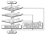
- FIG. 6 is a flowchart describing the operation of the brake controlling apparatus according to the present invention.
- FIG. 1 to FIG. 6 An embodiment of a brake controlling apparatus according to the present invention will be described based on FIG. 1 to FIG. 6 .
- the brake controlling apparatus of the present embodiment performs the control of braking torque (braking force) generated with respect to each wheel W FL , W FR , W RL , W RR by a braking device, to be described later, and is prepared as one function of an electronic control unit (ECU) 1 shown in FIG. 1 .
- the electronic control unit 1 is configured by a CPU (Central Processing Unit) (not shown), ROM (Read Only Memory) for storing a predetermined control program etc. in advance, RAM (Random Access Memory) for temporarily storing the calculation result of the CPU, backup RAM for storing information etc. prepared in advance, and the like.
- CPU Central Processing Unit
- ROM Read Only Memory
- RAM Random Access Memory
- FIG. 1 one example of a braking device to be controlled by the brake controlling apparatus is shown in FIG. 1 .
- a vehicle is mounted with a power source such as an engine or a motor (not shown), and travels by transmitting the power of the power source to the drive wheel as drive force.
- the braking device is used to stop or decelerate the vehicle that is traveling, and is configured to generate a target braking torque (target braking force) at individual magnitude with respect to each wheel W FL , W FR , W RL , W RR .
- target braking torque target braking force
- the frictional force is generated between engaging elements using the force of the brake liquid pressure to act the target braking torque (target braking force) on the wheels W FL , W FR , W RL , W RR .
- the braking device includes a brake pedal 10 to be operated by a driver, a brake liquid pressure generating means 20 for generating the brake liquid pressure corresponding to an operation amount of the brake pedal 10 , a braking force generating means (drum brake, disc brake, etc.) 30 FL , 30 FR , 30 RL , 30 RR for each wheel W FL , W FR , W RL , W RR for generating the braking force by being supplied with the brake liquid pressure, and a brake liquid pressure adjusting means 40 for supplying the brake liquid pressure generated by the brake liquid pressure generating means 20 as is or adjusting such brake liquid pressure for each wheel W FL , W FR , W RL , W RR and supplying to the respective braking force generating means 30 FL , 30 FR , 30 RL , 30 RR (specifically, cylinder of the braking force generating means 30 FL , 30 FR , 30 RL , 30 RR such as a wheel cylinder of the drum brake,
- the brake liquid pressure generating means 20 includes a braking servo means (brake booster) 21 for doubling an operation pressure (pedal depression force) involved in brake operation of the driver input to the brake pedal 10 at a predetermined double force ratio, a master cylinder 22 for converting the pedal depression force doubled by the braking booster 21 to the brake liquid pressure (hereinafter referred to as “master cylinder pressure”) Pmc corresponding to the operation amount of the brake pedal 10 , and a reservoir tank 23 for storing the brake liquid.
- a braking servo means brake booster 21 for doubling an operation pressure (pedal depression force) involved in brake operation of the driver input to the brake pedal 10 at a predetermined double force ratio
- master cylinder 22 for converting the pedal depression force doubled by the braking booster 21 to the brake liquid pressure (hereinafter referred to as “master cylinder pressure”) Pmc corresponding to the operation amount of the brake pedal 10
- master cylinder pressure a brake liquid pressure
- the braking device of the present embodiment includes first and second brake liquid pressure pipings 24 , 25 having one of respective ends connected to the respective brake liquid pressure chambers, and the other end connected to the first brake liquid pressure circuit system and the second brake liquid pressure circuit system, respectively.
- the master cylinder pressure Pmc is supplied to the right front wheel W FR and the left rear wheel W RL according to the control mode, to be described later, of the first brake liquid pressure circuit system, and to the left front wheel W FL and the right rear wheel W RR according to the control mode, to be described later, of the second brake liquid pressure circuit system.
- the brake liquid pressure adjusting means 40 is a so-called brake actuator for supplying the brake liquid pressure (master cylinder pressure Pmc) in the first and second brake liquid pressure pipings 24 , 25 as is or adjusting such brake liquid pressure to the respective braking force generating means 30 FR , 30 RL , 30 RR , 30 FL .
- the brake liquid pressure adjusting means 40 operates according to a control command of the brake liquid pressure controlling means of the electronic control unit 1 .
- the brake liquid pressure supplied to the braking force generating means 30 FR , 30 RL , 30 RR , 30 FL is referred to as the “brake cylinder pressure Pbc”.
- the brake liquid pressure adjusting means 40 of the present embodiment is illustrated to include the first brake liquid pressure circuit system for controlling and transmitting the brake cylinder pressure Pbc with respect to the right front wheel W FR and the left rear wheel W RL , and the second brake liquid pressure circuit system for controlling and transmitting the brake cylinder pressure Pbc with respect to the left front wheel W FL and the right rear wheel W RR . That is, the brake liquid pressure adjusting means 40 has a structure including the brake liquid pressure circuit of a so-called X-piping.
- the upstream side (master cylinder 22 side) of the first brake liquid pressure circuit system is connected to the first brake liquid pressure piping 24 and the downstream side is connected to a brake liquid pressure piping 31 FR of the right front wheel W FR and a brake liquid pressure piping 31 RL of the left rear wheel W RL .
- the upstream side of the second brake liquid pressure circuit system is connected to the second brake liquid pressure piping 25 and the downstream side is connected to a brake liquid pressure piping 31 RR of the right rear wheel W RR and a brake liquid pressure piping 31 FL of the left front wheel W FL .
- the upstream side and the downstream side in the flowing direction of the brake liquid at the time of pedal operation are respectively the upstream side and the downstream side of the brake liquid pressure circuit of the braking device.
- the brake liquid pressure adjusting means 40 includes a master cylinder pressure sensor 41 for detecting the brake liquid pressure (i.e., master cylinder pressure Pmc) supplied from the brake liquid pressure generating means 20 .
- the master cylinder pressure sensor 41 is arranged on one of either the first or second brake liquid pressure pipings 24 , 25 , and transmits the detection signal to the electronic control unit 1 .
- the master cylinder pressure sensor 41 is illustrated as being arranged on the first brake liquid pressure piping 24 herein.
- the brake liquid pressure adjusting means 40 also includes master cut valves 42 , 43 serving as a flow rate adjusting means of the brake liquid in the first and second brake liquid pressure circuit systems, respectively.
- the upstream side of each master cut valve 42 , 45 is connected to the first and second brake liquid pressure pipings 24 , 25 , respectively, and the master cut valve 42 is arranged on the downstream of the master cylinder pressure sensor 41 .
- Such master cut valves 42 , 43 are flow rate adjusting electromagnetic valves of a so-called constantly-open type that are usually in the open state, where the control of the valve opening is executed with the current flow by the brake liquid pressure controlling means of the electronic control unit 1 .
- the respective master cut valves 42 , 43 release one part of the pressure of the brake liquid discharged from pressurization pumps 69 A, 69 B, to be described later, towards the master cylinder 22 side to adjust the brake liquid pressure to supply to the braking force generating means 30 FR , 30 RL , 30 RR , 30 FL side.
- each master cut valve 42 , 43 is connected to a coupling passage 44 , 45 , respectively. That is, in the brake liquid pressure adjusting means 40 , the first brake liquid pressure piping 24 is connected to the coupling passage 44 through the master cut valve 42 , and the second brake liquid pressure piping 25 is connected to the coupling passage 45 through the master cut valve 43 .
- Two branched passages 46 , 47 are connected to the coupling passage 44 of the first brake liquid pressure circuit system so as to be branched therefrom, and two branched passages 48 , 49 are connected to the coupling passage 45 of the second brake liquid pressure circuit system so as to be branched therefrom.
- the respective branched passages 46 , 47 is connected to the brake liquid pressure piping 31 FR of the right front wheel W FR and the brake liquid pressure piping 31 RL of the left rear wheel W RL .
- the respective branched passages 48 , 49 is connected to the brake liquid pressure piping 31 RR of the right rear wheel W RR and the brake liquid pressure piping 31 FL of the left front wheel W FL .
- a brake liquid pressure adjusting unit capable of individually adjusting the brake cylinder pressure Pbc to the respective braking force generating means 30 FR , 30 RL , 30 RR , 30 FL is arranged for every wheel W FR , W RL , W RR , W FL on each branched passage 46 , 47 , 48 , 49 .
- Each brake liquid pressure adjusting unit has a pressure boost mode of boosting the brake cylinder pressure Pbc to the respective braking force generating means 30 FL , 30 FR , 30 RL , 30 RR to be controlled, a holding mode of holding the brake cylinder pressure Pbc at the magnitude of the relevant point, and a depressurization mode of depressurizing the brake cylinder pressure Pbc for the main brake liquid pressure control mode.
- the respective brake liquid pressure adjusting units are configured by booster valves (also referred to as holding valves) 50 , 51 , 52 , 53 , brake liquid pressure discharge passages 54 , 55 , 56 , 57 , and depressurization valves 58 , 59 , 60 , 61 prepared for every wheel W FR , W RL , W RR , W FL .
- the booster valves 50 , 51 , 52 , 53 are respectively arranged on each branched passage 46 , 47 , 48 , 49 .
- Each of the brake liquid pressure discharge passages 54 , 55 , 56 , 57 is connected to the downstream side than each booster valve 50 , 51 , 52 , 53 in each branched passage 46 , 47 , 48 , 49 so as to be branched therefrom.
- the depressurization valves 58 , 59 , 60 , 61 are arranged on each brake liquid pressure discharge passage 54 , 55 , 56 , 57 , respectively.
- the respective booster valves 50 , 51 , 52 , 53 are electromagnetic valves of so-called constantly-open type and are in an open state in the usual time of non-excitation state, and are closed when becoming the excitation state with the current flow by the brake liquid pressure controlling means of the electronic control unit 1 .
- Each depressurization valve 58 , 59 , 60 , 61 is an electromagnetic valve of a so-called constantly-closed type and is in a closed state in the usual time of non-excitation state, and is opened when becoming the excitation state with the current flow by the brake liquid pressure controlling means.
- a brake liquid pressure discharge assembled passage 62 that unites the respective brake liquid pressure discharge passages 54 , 55 of the first brake liquid pressure circuit system, and a brake liquid pressure discharge assembled passage 63 that unites the respective brake liquid pressure discharge passages 56 , 57 of the second brake liquid pressure circuit system are prepared, where each brake liquid pressure discharge assembled passage 62 , 63 is connected to an auxiliary reservoir 64 , 65 , respectively.
- a pump passage 66 branched from a branched point J 1 of the coupling passage 44 and each branched passage 46 , 47 and connected to the brake liquid pressure discharge assembled passage 62 is arranged in the first brake liquid pressure circuit system.
- a pump passage 67 branched from a branched point J 2 of the coupling passage 45 and each branched passage 48 , 49 and connected to the brake liquid pressure discharge assembled passage 63 is arranged in the second brake liquid pressure circuit system.
- the pressurization pumps 69 A, 69 B of the first brake liquid pressure circuit system side and the second brake liquid pressure circuit system side driven by one electric motor 68 are arranged on the pump passages 66 , 67 , respectively.
- Each pump passage 66 , 67 is configured by a passage on the intake side of the brake liquid (hereinafter referred to as “pump intake side passage) 66 a , 67 a of the pressurization pump 69 A, 69 B, and a passage on the discharge side of the brake liquid (hereinafter referred to as “pump discharge side passage) 66 b , 67 b of the pressurization pump 69 A, 69 B.
- Each pump intake side passage 66 a , 67 a has one end connected to the brake liquid pressure discharge assembled passage 62 , 63 and the other end connected to the intake port of the pressurization pump 69 A, 69 B.
- Each pump discharge side passage 66 b , 67 b has one end connected to the discharge port of the pressurization pump 69 A, 69 B, and the other end connected to the branched point J 1 , J 2 .
- Each pressurization pump 69 A, 69 B is a brake liquid pressurizing means for pumping up the brake liquid through the pump intake side passage 66 a , 67 a from the auxiliary reservoir 64 , 65 and pressurizing the same, and discharging the brake liquid towards each branched point J 1 , J 2 , and supplies the pressurized brake liquid pressure (hereinafter referred to as “pressurized brake pressure”) Pba towards each branched point J 1 , J 2 .
- pressurized brake pressure pressurized brake pressure
- the brake liquid pressure controlling means of the electronic control unit 1 operates the pressurization pumps 69 A, 69 B corresponding to the braking force generating means 30 FL , 30 FR , 30 RL , 30 RR to be boosted when the boost request (hereinafter referred to as “pressurization brake request”) of the brake cylinder pressure Pbc of the braking force generating means 30 FL , 30 FR , 30 RL , 30 RR using the pressurized brake pressure Pba is made.
- the pressurized brake pressure Pba is supplied to the brake liquid pressure piping (upstream side of booster valves 50 , 51 on pump discharge side passage 66 b , coupling passage 44 , and branched passages 46 , 47 ) between the pressurization pump 69 A, the master cut valve 42 , and the booster valves 50 , 51 by operating the pressurization pump 69 A.
- the brake liquid pressure piping therebetween is hereinafter collectively referred to as “pressure adjusting unit upstream piping”.
- the brake liquid pressure (hereinafter also referred to as “pressure adjusting unit upstream brake pressure”) Psm in which the master cylinder pressure Pmc and the pressurized brake pressure Pba are combined is supplied to the pressure adjusting unit upstream piping.
- the pressurized brake pressure Pba is supplied to the pressure adjusting unit upstream piping (upstream side of booster valves 52 , 53 on pump discharge side passage 67 b , coupling passage 45 , and branched passages 48 , 49 ) between the pressurization pump 69 B, the master cut valve 43 , and the booster valves 52 , 53 by operating the pressurization pump 69 B.
- the pressure adjusting unit upstream brake pressure Psm in which the master cylinder pressure Pmc and the pressurized brake pressure Pba are combined is supplied to the pressure adjusting unit upstream piping.
- the electric motor 68 is driven by the power supply from a battery (not illustrated).
- Each pressurization pump 69 A, 69 B may be driven by an individual electric motor.
- a piston pump in which the brake liquid is taken in and discharged by the reciprocating movement of the piston built therein is used for the pressurization pumps 69 A, 69 B of the present embodiment.
- Such pressurization pumps 69 A, 69 B are hereinafter referred to as “piston pumps 69 A, 69 B”.
- a so-called opposed type piston pump 69 in which the piston pumps 69 A, 69 B are arranged facing each other will be described by way of example.
- the opposed type piston pump 69 includes two pistons 691 A, 691 B accommodated in a housing 690 , and elastic members 692 A, 692 B such as a helical spring for pushing back the pistons 691 A, 691 B pushed in one direction to the other direction.
- the housing 690 is formed with piston operation chambers 693 A, 693 B for reciprocating the pistons 691 A, 691 B.
- the piston operation chambers 693 A, 693 B are formed to communicate with the pump passages 66 , 67 , respectively.
- the piston 691 A, the elastic member 692 A, and the piston operation chamber 693 A configure the pressurization pump 69 A of the first brake liquid pressure circuit system
- the piston 691 B, the elastic member 692 B, and the piston operation chamber 693 B configure the pressurization pump 69 B of the second brake liquid pressure circuit system.
- the pistons 691 A, 691 B move through the piston operation chambers 693 A, 693 B by the elastic force of the elastic members 692 A, 692 B, respectively, to take in the brake liquid from the pump intake side passages 66 a , 67 a .
- Such brake liquid flows into the piston operation chambers 693 A, 693 B, and is discharged to the pump discharge side passages 66 b , 67 b by moving the pistons 691 A, 691 B in the direction opposite to the previous moving direction.
- the movement of the pistons 691 A, 691 B in the opposite direction is carried out using the power of the electric motor 68 .
- an eccentric cam 68 b is attached to an output shaft 68 a of the electric motor 68 with the axis core shifted, and the outer peripheral surface of the eccentric cam 68 b is contacted to one end of the pistons 691 A, 691 B.
- the eccentric cam 68 b rotates with the rotation of the output shaft 68 a of the electric motor 68 , and pushes the pistons 691 A, 691 B in the direction against the elastic force of the elastic members 692 A, 692 B.
- the pump discharge side passages 66 b , 67 b include orifices 71 , 72 , respectively.
- the master cylinder pressure Pmc becomes difficult to act on the discharge port by arranging such orifices 71 , 72 , and hence the discharging operation of the brake liquid will not be inhibited.
- the brake liquid pressure adjusting means 40 includes intake passages 73 , 74 for connecting the upstream side of the master cut valves 42 , 43 in the first and second brake liquid pressure pipings 24 , 25 and the auxiliary reservoirs 64 , 65 , respectively.
- Reservoir cut check valves 75 , 76 are arranged on the auxiliary reservoirs 64 , 65 sides of the respective intake passages 73 , 74 .
- the braking device of the present embodiment configured as above has the operation at the time of braking control controlled by the electronic control unit 1 .
- the electronic control unit 1 receives the operation amount of the brake pedal 10 detected by a brake pedal operation amount detecting means 11 shown in FIG. 1 , and the master cylinder pressure Pmc detected by the master cylinder pressure sensor 41 . That is, the electronic control unit 1 receives the information of the brake pedal operation amount detected when the driver makes the brake request by the operation of the brake pedal 10 , and the information of the master cylinder pressure Pmc generated with such operation.
- the operation amount of the brake pedal 10 includes the depression amount and the pedal depression force of the brake pedal 10 .
- the brake pedal operation amount detecting means 11 may be a pedal stroke sensor or a pedal depression force sensor.
- the request vehicle braking force calculating means of the electronic control unit 1 calculates the request vehicle braking force of the driver based on the operation amount of the brake pedal 10 . For instance, the request vehicle braking force is obtained through a calculation method well known in the art.
- the brake liquid pressure controlling means of the electronic control unit 1 controls the brake liquid pressure adjusting means 40 so that the request vehicle braking force acts on the vehicle by the sum of the braking forces of all the wheels W FL , W FR , W RL , W RR .
- the brake liquid pressure is distributed to the respective braking force generating means 30 FL , 30 FR , 30 RL , 30 RR at a predetermined distribution ratio or at a distribution ratio corresponding to the state of the vehicle.
- the brake liquid pressure controlling means controls the brake liquid pressure adjusting unit to be controlled to the pressure boost mode when increasing the braking force of the wheels W FR , W RL , W RR , W FL .
- the brake liquid pressure controlling means controls the master cut valves 42 , 43 and the booster valves 50 , 51 , 52 , 53 corresponding to the wheels W FR , W RL , W RR , W FL to the open state, and the depressurization valves 58 , 59 , 60 , 61 to the closed state.
- the brake liquid pressure controlling means performs the control so as not to drive the piston pumps 69 A, 69 B by stopping the electric motor 68 .
- the master cylinder pressure Pmc increases and decreases according to the operation amount of the brake pedal 10 of the driver. Therefore, the braking force generated at the wheels W FL , W FR , W RL , W RR in this case has a magnitude corresponding to the operation amount of the brake pedal 10 of the driver.
- the sum of the braking forces of the wheels W FL , W FR , W RL , W RR generated without driving the piston pumps 69 A, 69 B is referred to as the “reference vehicle braking force”.
- the reference vehicle braking force may not satisfy the request vehicle braking force. For instance, when a sudden depression speed of the brake pedal 10 exceeding a predetermined speed is detected, determination is made that the vehicle braking force stronger than that corresponding to the operation amount of the brake pedal 10 is requested and the request vehicle braking force calculating means requests the request vehicle braking force greater than at the time of the normal brake request, and hence the request vehicle braking force may not be generated at the vehicle with only the reference vehicle braking force based on the master cylinder pressure Pmc.
- the brake liquid pressure controlling means determines that the pressurization brake request is made, and performs the BA (Brake Assist) control of causing the vehicle to generate the request vehicle braking force while compensating for the lack of operation amount of the brake pedal 10 .
- the brake liquid pressure controlling means controls the electric motor 68 and drives the piston pumps 69 A, 69 B, and supplies the pressurized brake pressure Pba to the upstream piping of the pressure adjusting unit.
- the brake liquid pressure controlling means adjusts the opening degree of the booster valves 50 , 51 , 52 , 53 as necessary, and the brake liquid pressure lower than the pressure adjusting unit upstream brake pressure Psm is supplied to the braking force generating means 30 FL , 30 FR , 30 RL , 30 RR as the brake cylinder pressure Pbc (Psm>Pbc).
- the opening degree of the booster valves 50 , 51 , 52 , 53 is determined based on the request vehicle braking force.
- the braking force corresponding to the brake cylinder pressure Pbc thus generates at the wheels W FL , W FR , W RL , W RR , and the request vehicle braking force acts on the vehicle.
- the depression speed of the brake pedal 10 can be calculated based on the operation amount of the brake pedal 10 and the elapsed time of the operation, but means for detecting the depression speed (brake operation speed detecting means) may be separately arranged.
- the brake liquid pressure controlling means controls the brake liquid pressure adjusting unit to be controlled to the depressurization mode.
- the brake liquid pressure controlling means in this case controls the master cut valves 42 , 43 and the booster valves 50 , 51 , 52 , 53 corresponding to the wheels W FR , W RL , W RR , W FL to the closed state, and the depressurization valves 58 , 59 , 60 , 61 to the open state.
- the brake cylinder pressure Pbc to supply to the braking force generating means 30 FR , 30 RL , 30 RR , 30 FL is depressurized, and the braking force reduces.
- the piston pumps 69 A, 69 B are controlled to the non-driven state.
- the brake liquid pressure controlling means controls the brake liquid pressure adjusting unit to the holding mode after boosting or depressurizing the brake cylinder pressure Pbc of the braking force generating means 30 FR , 30 RL , 30 RR , 30 FL to be controlled.
- the brake liquid pressure controlling means in this case controls the master cut valves 42 , 43 , the booster valves 50 , 51 , 52 , 53 and the depressurization valves 58 , 59 , 60 , 61 of the wheels W FR , W RL , W RR , W FL to be controlled to be in the closed state.
- the brake cylinder pressure Pbc of the braking force generating means 30 FL , 30 FR , 30 RL , 30 RR is thereby held at a constant magnitude in the wheels W FL , W FR , W RL , W RR to be controlled.
- the braking device can execute ABS (Antilock Brake System) control by alternately switching the pressure boost mode and the depressurization mode, or alternately switching the pressure boost mode, the depressurization mode, and the holding mode.
- the brake liquid pressure controlling means mainly controls the switching operation so that the wheels W FL , W FR , W RL , W RR are not in a wheel lock state or a wheel slip state.
- the wheel lock state and the wheel slip state may be determined based on the rotation speed (wheel speed) of each wheel W FL , W FR , W RL , W RR detected by wheel speed detecting means 81 FL , 81 FR , 81 RL , 81 RR .
- the braking device is also used for the vehicle behavior control for stabilizing the behavior of the vehicle.
- the vehicle behavior control may stabilize the position at the time of vehicle pivoting, and is executed by a vehicle behavior control device.
- the vehicle behavior control device is also prepared as one function of the electronic control unit 1 .
- FIG. 3 One example of a vehicle 100 applied with the braking device and the vehicle behavior control device thereof is shown in FIG. 3 .
- a steering device for steering the steering wheel W FL , W FR by the steering operation of the driver is prepared in the vehicle 100 .
- the steering device includes a steering wheel 111 to be operated by the driver, a steering shaft 112 coupled to the steering wheel 111 , a steering torque transmitting means 113 for transmitting the steering torque of the steering shaft 112 towards the left and right steering wheels W FL , W FR , tie rods 114 L, 114 R for coupling the steering torque transmitting means 113 and each steering wheel W FL , W FR , and a steering operation amount detecting means 115 for detecting the steering operation amount of the steering wheel 111 by the driver.
- the steering torque transmitting means 113 is a so-called rack and pinion mechanism configured by a pinion gear 113 a arranged at a distal end of the steering shaft 112 and a rack gear 113 b that meshes with the pinion gear 113 a .
- the left and right tie rods 114 L, 114 R are respectively coupled to the both ends of the rack gear 113 b , and each steering wheel W FL , W FR coupled to each tie rod 114 L, 114 R is rolled with the movement of the rack gear 113 b.
- the steering operation amount is such as a steering angle.
- the steering operation amount detecting means 115 detects the steering angle from the rotation angle of the steering shaft 112 and transmits the detection signal to the electronic control unit 1 .
- the steering angular speed is calculated based on the amount of change by the elapse of time of the steering angle in the electronic control unit 1 .
- the steering device in which the steering wheel 111 and the steering wheels W FL , W FR are mechanically connected is illustrated, but the steering device may be a so-called steer by wire type in which mechanical connection is not made.
- the vehicle behavior controlling means of the vehicle behavior control device determines the behavior at the time of pivoting of the vehicle 100 based on the steering angle detected by the steering operation amount detecting means 115 , the yaw rate detected by a yaw rate sensor 82 , and the vehicle transverse acceleration detected by a vehicle transverse acceleration detecting means 83 shown in FIG. 3 . If detected as a result of the determination that an excessively large yaw moment My 1 acts on the vehicle body, the vehicle behavior controlling means performs the control to suppress the excessively large yaw moment My 1 to enable a stable pivoting operation.
- the vehicle behavior controlling means determines that the pressurization brake request is made and transmits a command to the brake liquid pressure controlling means, and applies the requested braking force for generating the yaw moment My 2 ( ⁇ My 1 ) in the direction opposite to the excessively large yaw moment My 1 at the vehicle body at the pivoting outer wheels (left front wheel W FL or right front wheel W FR ) on the front side. That is, the vehicle behavior controlling means performs the so-called VSC (Vehicle Stability Control) control.
- VSC Vehicle Stability Control
- the brake liquid pressure controlling means that received the command controls the brake liquid pressure adjusting means 40 in the following manner to generate the desired requested braking force at the pivoting wheels (left front wheel W FL or right front wheel W FR ) on the front side to be controlled.
- the brake liquid pressure controlling means in this case steps up the brake cylinder pressure Pbc with respect to the wheel to be controlled while alternately repeating boosting and holding, and controls the brake liquid pressure adjusting unit to be controlled to apply the requested braking force that realizes the yaw moment My 2 in the opposite direction on the relevant wheel.
- the brake liquid pressure controlling means controls the booster valves 50 , 53 corresponding to the wheels (left front wheel W FL or right front wheel W FR ) to be controlled to the open state, and also controls the master cut valves 42 , 43 and the depressurization valves 58 , 61 to the close state, and also controls the electric motor 68 to drive the piston pumps 69 A, 69 B.
- the brake liquid pressure controlling means closes the booster valves 50 , 53 from the boosted state. That is, when performing the vehicle behavior control, the brake liquid pressure controlling means alternately repeats opening and closing with respect to the booster valves 50 , 53 corresponding to the wheels to be controlled.
- the piston pumps 69 A, 69 B of the braking device have an intake stroke and a discharge stroke of the brake liquid while the pistons 691 A, 691 B reciprocate once, where a dischargeable period (hereinafter referred to as “pump dischargeable period”) Tpq and a non-dischargeable period (hereinafter referred to as “pump non-dischargeable period”) Tp 0 of the brake liquid alternately exist during that time (i.e., during one cycle Tp).
- a dischargeable period hereinafter referred to as “pump dischargeable period”
- Tp 0 non-dischargeable period
- the pressurized brake pressure Pba having the magnitude similar to that in the pump dischargeable period Tpq is not supplied to the pressure adjusting unit upstream piping and the brake cylinder pressure Pbc becomes lower than the requested value.
- the pressure adjusting unit upstream brake pressure Psm of the pressure adjustment unit upstream piping involves the pulse pressure fluctuation depending on the setting of the duty ratio (i.e., opening period (hereinafter also referred to as “booster valve opening period”)) Tvopen and closing period (hereinafter also referred to as “booster valve closing period”) of the booster valves 50 , 51 , 52 , 53 since the piston pumps 69 A, 69 B include the pump dischargeable period Tpq and the pump non-dischargeable period Tp 0 during one cycle Tp.
- the duty ratio i.e., opening period (hereinafter also referred to as “booster valve opening period”)
- Tvopen and closing period hereinafter also referred to as “booster valve closing period”
- the step-up gradient of the brake cylinder pressure Pbc to be supplied to the wheel to be controlled becomes small, whereby it constantly becomes difficult to step up the brake cylinder pressure Pbc to the requested value than in the state in which the brake liquid is discharged from the pump. Therefore, the desired brake cylinder pressure Pbc becomes difficult to be supplied to the relevant wheel at an appropriate timing in this case, and hence the yaw moment My 2 in the opposite direction by the application of the braking force on the wheel cannot be generated at the vehicle at an optimum timing, and the control accuracy of the brake liquid pressure in the vehicle behavior control may lower.
- the pressure adjusting unit upstream brake pressure Psm immediately lowers and the brake cylinder pressure Pbc becomes difficult to be raised when stepping up the downstream side of the booster valves 50 , 51 , 52 , 53 (i.e., brake cylinder pressure Pbc of the braking force generating means 30 FR , 30 RL , 30 RR , 30 FL ) by the repeated operation of opening and closing the booster valves 50 , 51 , 52 , 53 since the discharge amount of the brake liquid from the piston pumps 69 A, 69 B is generally small.
- the master cylinder pressure Pmc involved in the brake operation of the driver is generated.
- the master cylinder pressure Pmc increases and decreases according to the operation amount of the brake pedal 10 , and may become high or low with respect to the brake cylinder pressure Pbc by the brake operation of the driver.
- the master cylinder pressure Pmc is greater than or equal to the brake cylinder pressure Pbc and is less likely to be subjected to the influence of the pulse pressure fluctuation even if the piston pumps 69 A, 69 B are operated as necessary, and thus the brake cylinder pressure Pbc can be stepped up as desired by the setting of the duty ratio of the booster valves 50 , 51 , 52 , 53 (i.e., normal open/close control of booster valves 50 , 51 , 52 , 53 ) similar to the conventional art.
- the pressurized brake pressure Pba of the piston pumps 69 A, 69 B is required to step up the brake cylinder pressure Pbc of the wheels W FL , W FR , W RL , W RR to be controlled.
- the brake cylinder pressure Pbc may not be stepped up as desired due to the lowering of the pressure adjusting unit upstream brake pressure Psm involved in the pulse pressure fluctuation and the opening of the booster valves 50 , 51 , 52 , 53 .
- the brake controlling apparatus of the present embodiment is configured to supply the brake cylinder pressure Pbc having a desired magnitude at a desired timing at the time of request to boost the brake cylinder pressure Pbc with respect to the wheels W FL , W FR , W RL , W RR to be controlled even when the piston pumps 69 A, 69 B are used as pressurizing means of the brake liquid of the braking device.
- the booster valves 50 , 51 , 52 , 53 described above perform the opening operation and the closing operation based on the set duty ratio (ratio between the closing period Tvclose and the opening period Tvopen).
- control is performed such that the pump dischargeable period Tpq of the target piston pumps 69 A, 69 B appears in the opening period Tvopen of the booster valves 50 , 51 , 52 , 53 related to the wheels W FR , W RL , W RR , W FL to be controlled by adjusting the duty ratio.
- the duty ratio is to be set so that the opening period Tvopen of the booster valve becomes at least the pump dischargeable period Tpq (1 ⁇ 2 cycle of piston pumps 69 A, 69 B).
- the open/close control of the booster valves 50 , 51 , 52 , 53 to be controlled is carried out based on the duty ratio, the pump dischargeable period Tpq of the piston pumps 69 A, 69 B appears in the opening period Tvopen of the booster valves 50 , 51 , 52 , 53 , and hence the lowering of the pressure adjusting unit upstream brake pressure Psm involved in the pulse pressure fluctuation and the opening of the booster valves 50 , 51 , 52 , 53 can be suppressed, and the brake cylinder pressure Pbc can be stepped up at the desired magnitude and timing without causing lowering of the step-up gradient.
- the responsiveness of the discharge of the brake liquid of the piston pumps 69 A, 69 B is inferior to the responsiveness of the opening of the booster valves 50 , 51 , 52 , 53 .
- the pressurized brake pressure Pba pressurized by the piston pumps 69 A, 69 B cannot reach the pressure adjusting unit upstream piping (i.e., upstream side of booster valves 50 , 51 , 52 , 53 ) and the desired brake liquid pressure may not be transmitted to the wheels W FR , W RL , W RR , W FL to be controlled at the beginning of the opening of the booster valves 50 , 51 , 52 , 53 .
- the brake liquid pressure controlling means desirably sets the duty ratio so that the opening period Tvopen of the booster valves 50 , 51 , 52 , 53 related to the wheels W FR , W RL , W RR , W FL to be controlled becomes longer than the pump dischargeable period Tpq in the piston pumps 69 A, 69 B.
- the one cycle Tp of the piston pumps 69 A, 69 B changes according to the output rotation number of the electric motor 68 , and is the inverse number of the output rotation number per one second of the electric motor 68 .
- the output rotation number of the electric motor 68 can be grasped by the application voltage to the electric motor 68 .
- the duty ratio in which the open valve period Tvopen of the booster valves 50 , 51 , 52 , 53 related to the wheels W FR , W RL , W RR , W FL to be controlled becomes at least an inverse number of the output rotation number per one second of the electric motor 68 is set, and the open/close state of the booster valves 50 , 51 , 52 , 53 is controlled based on such duty ratio.
- the pump dischargeable period Tpq appears during the opening period Tvopen of the booster valve on a constant basis by setting the duty ratio of the booster valves 50 , 51 , 52 , 53 that satisfies the condition.
- the duty ratio of the booster valves 50 , 51 , 52 , 53 may vary the opening period Tvopen of the booster valve or the closing period Tvclose of the booster valve as long as the condition that the opening period Tvopen of the booster valve becomes at least one cycle Tp of the piston pumps 69 A, 69 B.
- the set state shown in FIG. 5 in which the closing period Tvclose of the booster valve is shortened may be realized from the set state of FIG. 4 , in which case, the pump dischargeable period Tpq for one cycle Tp always appears during one opening period Tvopen of the booster valve.
- the brake liquid pressure controlling means of the present embodiment performs a determination on whether or not the pressurization brake request is made (step ST 1 ). If the pressurization brake request is not made, the brake liquid pressure controlling means once terminates the present operation.
- the brake liquid pressure controlling means When determined that the pressurization brake request is made in step ST 1 , the brake liquid pressure controlling means performs a determination on whether or not in braking control (step ST 2 ).
- the brake liquid pressure controlling means compares the master cylinder pressure Pmc and the brake cylinder pressure Pbc to determine whether or not the master cylinder pressure Pmc is greater than or equal to the brake cylinder pressure Pbc (step ST 3 ).
- a value detected by the master cylinder pressure sensor 41 is used for the master cylinder pressure Pmc. As shown in FIG.
- pressure sensors 32 FL , 32 FR , 32 RL , 32 RR may be arranged in the respective brake liquid pressure pipings 31 FL , 31 FR , 31 RL , 31 RR , and the detection values of the pressure sensors 32 FL , 32 FR , 32 RL , 32 RR may be used for the brake cylinder pressure Pbc.
- the brake liquid pressure controlling means executes the usual open/close control of the booster valves 50 , 51 , 52 , 53 (step ST 4 ) since the influence of the pulse pressure fluctuation is less likely to be received.
- the brake liquid pressure controlling means open/close controls the booster valves 50 , 51 , 52 , 53 to be controlled according to the set duty ratio similar to the conventional art, and operates the piston pumps 69 A, 69 B as necessary if the requesting value of the brake cylinder pressure Pbc is high.
- the brake cylinder pressure Pbc of the wheels W FL , W FR , W RL , W RR to be controlled steps up to the requesting value at the appropriate magnitude and timing with the repeated open/close operation of the booster valves 50 , 51 , 52 , 53 . Therefore, the braking force generates at the desired appropriate magnitude and timing with respect to the wheels W FL , W FR , W RL , W RR to be controlled in the braking control in this case.
- the duty ratio at which the opening period Tvopen of the booster valves 50 , 51 , 52 , 53 to be controlled becomes at least greater than or equal to one cycle Tp (one cycle of the electric motor 68 ) of the piston pumps 69 A, 69 B is set in the brake liquid pressure controlling means to avoid the influence of lowering of the pressure adjusting unit upstream brake pressure Psm involved in the pulse pressure fluctuation and the opening of the booster valves 50 , 51 , 52 , 53 , and the open/close control of the booster valves 50 , 51 , 52 , 53 based on the duty ratio is executed (step ST 5 ).
- the brake liquid pressure controlling means operates the piston pumps 69 A, 69 B but has the pump dischargeable period Tpq of the piston pumps 69 A, 69 B constantly appearing in the opening period Tvopen of the booster valve by the duty ratio, and thus can supply the brake cylinder pressure stepped up at the desired magnitude and timing to the braking force generating means 30 FR , 30 RL , 30 RR , 30 FL of the wheels W FR , W RL , W RR , W FL to be controlled without being influenced by the lowering of the pressure adjusting unit upstream brake pressure Psm involved in the pulse pressure fluctuation and the opening of the booster valves 50 , 51 , 52 , 53 .
- the braking force can be generated with respect to the wheels W FL , W FR , W RL , W RR to be controlled at the desired appropriate magnitude and timing by the brake cylinder pressure Pbc of satisfactory control accuracy. That is, in such a case, the braking control of satisfactory control accuracy can be carried out even if inexpensive piston pumps 69 A, 69 B are used for the pressurization of the brake liquid.
- step ST 2 the brake liquid pressure controlling means proceeds to step ST 5 and sets the duty ratio of the booster valves 53 , 50 of the wheels (left front wheel W FL or right front wheel W FR ) to be controlled and performs the open/close control of the booster valves 53 , 50 based on such duty ratio.
- the brake liquid pressure controlling means can supply the brake cylinder pressure Pbc stepped up at the desired magnitude and timing to the braking force generating means 30 FL or the braking force generating means 30 FR of the wheels to be controlled without being influenced by the lowering of the pressure adjustment upstream brake pressure Psm involved in the pulse pressure fluctuation and the opening of the booster valves 53 , 50 although the piston pumps 69 A, 69 B are in operation since the duty ratio at which the opening period Tvopen becomes a period of longer than or equal to at least one cycle Tp (one cycle of the electric motor 68 ) of the piston pumps 69 A, 69 B is set.
- the necessary yaw moment My 2 in the opposite direction can be generated at the vehicle at an optimum timing in addition to the optimum braking force desired for the predetermined wheel by the brake cylinder pressure Pbc of satisfactory control accuracy in the vehicle behavior control, so that a stable pivoting operation with an excessively large yaw moment suppressed can be carried out. That is, in such a case, the vehicle behavior control of satisfactory control accuracy can be carried out using the inexpensive piston pumps 69 A, 69 B for the pressurization of the brake liquid.
- the brake controlling apparatus sets the duty ratio of the booster valves 50 , 51 , 52 , 53 related to the wheels W FR , W RL , W RR , W FL to be controlled to the value described above (at which the pump dischargeable period Tpq for one cycle Tp of the target piston pumps 69 A, 69 B constantly appear during the opening period Tvopen of the booster valves 50 , 51 , 52 , 53 ).
- the brake controlling apparatus performs the open/close control of the booster valves 50 , 51 , 52 , 53 based on the set duty ratio. Therefore, the brake cylinder pressure Pbc stepped up at the desired magnitude and timing without lowering the step up gradient is supplied to the braking force generating means 30 FL , 30 FR , 30 RL , 30 RR of the wheels W FL , W FR W RL , W RR to be controlled.
- the desired boosted brake cylinder pressure Pbc can be supplied at the appropriate timing corresponding to the boost request can be supplied to the braking force generating means 30 FR , 30 RL , 30 RR , 30 FL although the piston pumps 69 A, 69 B, which are advantageous than the gear pump in terms of cost price but cannot always discharge the brake liquid, are used.
- the brake controlling apparatus the reduction effect of the cost price due to the use of the piston pumps 69 A, 69 B can be obtained, the lowering of the control accuracy of the brake liquid pressure caused by the structural features of the piston pumps 69 A, 69 B can be prevented, the optimum brake cylinder pressure Pbc can be supplied to the wheels W FR , W RL , W RR , W FL to be controlled as needed.
- the brake controlling apparatus is less susceptible to the influence of pulse pressure fluctuation if the master cylinder pressure Pmc during the braking control is greater than or equal to the brake cylinder pressure Pbc, and thus can step up the brake cylinder pressure Pbc to the requesting value at the appropriate magnitude and timing by the duty ratio of the booster valves 50 , 51 , 52 , 53 similar to the conventional art.
- the brake controlling apparatus thus can ensure the control accuracy of the brake liquid pressure when performing the braking control and the vehicle behavior control even by using the inexpensive piston pumps 69 A, 69 B.
- the brake controlling apparatus is useful in a technique of enhancing the control accuracy at the time of the boost request of the brake liquid pressure in the braking device using the piston pump.
Landscapes
- Engineering & Computer Science (AREA)
- Physics & Mathematics (AREA)
- Fluid Mechanics (AREA)
- Transportation (AREA)
- Mechanical Engineering (AREA)
- Electromagnetism (AREA)
- Regulating Braking Force (AREA)
Abstract
A brake controlling apparatus (electronic control unit) of a braking device including a booster valve to be opened at a time of request to boost a pressure of a brake liquid to supply to a wheel to be controlled, and a piston pump for supplying pressurized brake liquid to an upstream side of the booster valve, the brake controlling apparatus including a brake liquid pressure controlling unit that sets a duty ratio between a closing period and a opening period of the booster valve so that a dischargeable period of the brake liquid in the piston pump appears in the opening period of the booster valve and controls the booster valve based on the duty ratio.
Description
The present invention relates to a brake controlling apparatus for performing an operation control of a braking device using a piston pump for pressurizing a brake liquid.
A brake actuator of the braking device is conventionally configured by a plurality of electromagnetic valves arranged on a path of the brake liquid, a pressurization pump for pressurizing the brake liquid to supply to the wheel to realize a request to boost the brake liquid with respect to the relevant wheel, a motor for driving the pressurization pump, and the like. The known pressurization pump includes not only a gear pump in which the brake liquid is taken in and discharged with the rotation of the gear generally used in the conventional art, but also a piston pump in which the brake liquid is taken in and discharged by the reciprocating movement of the piston that excels in terms of cost price. For instance, the braking device including the piston pump is described in Patent Document 1. In the braking device of Patent Document 1, the timing to take in and discharge the brake liquid by the piston pump and the timing to open and close the electromagnetic valve (first electromagnetic open/close valve 46 and second electromagnetic open/close valves 48, 50) are synchronized to enhance the controllability of the brake liquid pressure.
Patent Document 2 describes a braking device in which an electromagnetic valve is arranged on a flow path of the brake liquid from a high hydraulic pressure source to a brake actuator, and the braking hydraulic pressure to supply to the brake actuator is controlled by adjusting a duty ratio of a drive signal of the electromagnetic valve. In such a braking device, a cycle of the drive signal is determined according to a vehicle speed, and a current is flowed to the electromagnetic valve according to the cycle.
- Patent Document 1: Japanese Patent Application Laid-open No. H08-310371
- Patent Document 2: Japanese Patent Application Laid-open No. H01-028060
Patent Document 3: Japanese Patent Application Laid-open No. 2006-069346
The gear pump can continue to discharge substantially a constant amount of brake liquid on a constant basis. The piston pump, on the other hand, takes in the brake liquid when the piston moves in one direction and discharges the brake liquid when the piston moves in the other direction, and thus a period in which the brake liquid can be discharged and a period in which the brake liquid cannot be discharged exists while the piston makes one reciprocation due to the structure. Therefore, the pressure boost amount of the brake liquid pressure becomes small when the non-dischargeable period of the brake liquid and the request period to boost the brake liquid pressure to the wheel to be controlled overlap, whereby the requested brake liquid pressure with respect to the wheel becomes difficult to generate when necessary. That is, when the piston pump is used as the pressurization pump of the brake actuator, the requested brake liquid pressure to the wheel to be controlled is not satisfied at an appropriate timing, and the requested braking force with respect to the wheel may not be generated when necessary.
In view of improving the drawbacks of the conventional art, it is an object of the present invention to provide a brake controlling apparatus capable of enhancing the control accuracy at the time of the boost request of the brake liquid pressure in the braking device that uses the piston pump.
In order to achieve the above mentioned object, in the present invention, a brake controlling apparatus of a braking device including a booster valve to be opened at a time of request to boost a pressure of a brake liquid to supply to a wheel to be controlled and a piston pump for supplying pressurized brake liquid to an upstream side of the booster valve, includes the brake liquid pressure controlling means sets the duty ratio of the booster valve so that the opening period of the booster valve becomes at least a period of longer than
or equal to one cycle of the piston pump.
In order to achieve the above mentioned object, in the present invention, a brake controlling apparatus of a braking device including a booster valve to be opened at a time of request to boost a pressure of a brake liquid to supply to a wheel to be controlled, and a piston pump for supplying pressurized brake liquid to an upstream side of the booster valve, includes a brake liquid pressure controlling means that sets a duty ratio between a closing period and a opening period of the booster valve so that the opening period of the booster valve becomes at least a dischargeable period of the brake liquid in the piston pump, and controls the booster valve based on the duty ratio, wherein the brake liquid pressure controlling means sets the duty ratio of the booster valve based on an output rotation number of the electric motor as a drive source of the piston pump.
It is preferable that the brake liquid pressure controlling means sets the duty ratio of the booster valve so that the opening period of the booster valve becomes at least an inverse number of an output rotation number per one second of the electric motor.
It is preferable that the brake liquid pressure controlling means is configured to set the duty ratio of the booster valve when a master cylinder pressure to apply on the upstream side of the booster valve is lower than the pressure of the brake liquid to the wheel to be controlled.
The brake controlling apparatus according to the present invention open/close controls the booster valve so that the dischargeable period of the brake liquid in the piston pump appears in the opening period (boost request period of the brake liquid pressure to the wheel to be controlled) of the booster valve, and thus can step up the brake liquid pressure to the wheel to be controlled at the desired magnitude and timing. Therefore, the requested braking force is generated at the desired timing at the wheel to be controlled. That is, the control accuracy of the brake liquid pressure to the wheel to be controlled at the time of boost request can be maintained in a satisfactory state although the piston pump which is advantageous than the gear pump in terms of cost price but cannot discharge the brake liquid on a constant basis is used, so that the desired appropriate fluid pressure can be supplied to the wheel to be controlled and the desired appropriate braking force can be generated at the wheel. For instance, the desired braking control having satisfactory control accuracy can be realized since an appropriate braking force can be generated with respect to each wheel during the braking control. Furthermore, the behavior of the vehicle can be stabilized under satisfactory control accuracy since an appropriate braking force can be generated with respect to the wheel to be controlled during the vehicle behavior control.
- 1 Electronic control unit (ECU)
- 10 Brake pedal
- 11 Brake pedal operation amount detecting means
- 20 Brake liquid pressure generating means
- 30 FL, 30 FR, 30 RL, 30 RR Braking force generating means
- 40 Brake liquid pressure adjusting means
- 42, 43 Master cut valve
- 50, 51, 52, 53 Booster valve
- 58, 59, 60, 61 Depressurization valve
- 68 Electric motor
- 68 b Eccentric cam
- 69 Opposed type piston pump
- 69A, 69B Piston pump (pressurization pump)
- 81 FL, 81 FR, 81 RL, 81 RR Wheel speed detecting means
- 82 Yaw rate sensor
- 83 Vehicle transverse acceleration detecting means
- 100 Vehicle
- 111 Steering wheel
- 113 Steering torque transmitting means
- 114L, 114R Tie rod
- 115 Steering operation amount detecting means
- 691A, 691B Piston
- 692A, 692B Elastic member
- WFL, WFR, WRL, WRR Wheel
Hereinafter, an embodiment of a brake controlling apparatus according to the present invention will be described in detail based on the drawings. It is understood that the present invention is not to be limited by the embodiment.
An embodiment of a brake controlling apparatus according to the present invention will be described based on FIG. 1 to FIG. 6 .
The brake controlling apparatus of the present embodiment performs the control of braking torque (braking force) generated with respect to each wheel WFL, WFR, WRL, WRR by a braking device, to be described later, and is prepared as one function of an electronic control unit (ECU) 1 shown in FIG. 1 . The electronic control unit 1 is configured by a CPU (Central Processing Unit) (not shown), ROM (Read Only Memory) for storing a predetermined control program etc. in advance, RAM (Random Access Memory) for temporarily storing the calculation result of the CPU, backup RAM for storing information etc. prepared in advance, and the like.
First, one example of a braking device to be controlled by the brake controlling apparatus is shown in FIG. 1 . A vehicle is mounted with a power source such as an engine or a motor (not shown), and travels by transmitting the power of the power source to the drive wheel as drive force. The braking device is used to stop or decelerate the vehicle that is traveling, and is configured to generate a target braking torque (target braking force) at individual magnitude with respect to each wheel WFL, WFR, WRL, WRR. Here, the frictional force is generated between engaging elements using the force of the brake liquid pressure to act the target braking torque (target braking force) on the wheels WFL, WFR, WRL, WRR.
As shown in FIG. 1 , the braking device includes a brake pedal 10 to be operated by a driver, a brake liquid pressure generating means 20 for generating the brake liquid pressure corresponding to an operation amount of the brake pedal 10, a braking force generating means (drum brake, disc brake, etc.) 30 FL, 30 FR, 30 RL, 30 RR for each wheel WFL, WFR, WRL, WRR for generating the braking force by being supplied with the brake liquid pressure, and a brake liquid pressure adjusting means 40 for supplying the brake liquid pressure generated by the brake liquid pressure generating means 20 as is or adjusting such brake liquid pressure for each wheel WFL, WFR, WRL, WRR and supplying to the respective braking force generating means 30 FL, 30 FR, 30 RL, 30 RR (specifically, cylinder of the braking force generating means 30 FL, 30 FR, 30 RL, 30 RR such as a wheel cylinder of the drum brake, a cylinder in a caliper of the disc brake, etc.).
First, the brake liquid pressure generating means 20 includes a braking servo means (brake booster) 21 for doubling an operation pressure (pedal depression force) involved in brake operation of the driver input to the brake pedal 10 at a predetermined double force ratio, a master cylinder 22 for converting the pedal depression force doubled by the braking booster 21 to the brake liquid pressure (hereinafter referred to as “master cylinder pressure”) Pmc corresponding to the operation amount of the brake pedal 10, and a reservoir tank 23 for storing the brake liquid.
Two brake liquid pressure chambers (hydraulic pressure chambers) (not shown) are arranged inside the master cylinder 22, and the master cylinder pressure Pmc is generated in the respective brake liquid pressure chambers. One of the master cylinder pressure Pmc generated in the respective brake liquid pressure chambers is supplied to a first brake liquid pressure circuit system, to be described later, of the brake liquid pressure adjusting means 40, and the other is supplied to a second brake liquid pressure circuit system, to be described later, of the brake liquid pressure adjusting means 40. Therefore, the braking device of the present embodiment includes first and second brake liquid pressure pipings 24, 25 having one of respective ends connected to the respective brake liquid pressure chambers, and the other end connected to the first brake liquid pressure circuit system and the second brake liquid pressure circuit system, respectively. For instance, the master cylinder pressure Pmc is supplied to the right front wheel WFR and the left rear wheel WRL according to the control mode, to be described later, of the first brake liquid pressure circuit system, and to the left front wheel WFL and the right rear wheel WRR according to the control mode, to be described later, of the second brake liquid pressure circuit system.
The brake liquid pressure adjusting means 40 will now be described. The brake liquid pressure adjusting means 40 is a so-called brake actuator for supplying the brake liquid pressure (master cylinder pressure Pmc) in the first and second brake liquid pressure pipings 24, 25 as is or adjusting such brake liquid pressure to the respective braking force generating means 30 FR, 30 RL, 30 RR, 30 FL. The brake liquid pressure adjusting means 40 operates according to a control command of the brake liquid pressure controlling means of the electronic control unit 1. In the following description, the brake liquid pressure supplied to the braking force generating means 30 FR, 30 RL, 30 RR, 30 FL is referred to as the “brake cylinder pressure Pbc”.
The brake liquid pressure adjusting means 40 of the present embodiment is illustrated to include the first brake liquid pressure circuit system for controlling and transmitting the brake cylinder pressure Pbc with respect to the right front wheel WFR and the left rear wheel WRL, and the second brake liquid pressure circuit system for controlling and transmitting the brake cylinder pressure Pbc with respect to the left front wheel WFL and the right rear wheel WRR. That is, the brake liquid pressure adjusting means 40 has a structure including the brake liquid pressure circuit of a so-called X-piping. The upstream side (master cylinder 22 side) of the first brake liquid pressure circuit system is connected to the first brake liquid pressure piping 24 and the downstream side is connected to a brake liquid pressure piping 31 FR of the right front wheel WFR and a brake liquid pressure piping 31 RL of the left rear wheel WRL. The upstream side of the second brake liquid pressure circuit system is connected to the second brake liquid pressure piping 25 and the downstream side is connected to a brake liquid pressure piping 31 RR of the right rear wheel WRR and a brake liquid pressure piping 31 FL of the left front wheel WFL. In the embodiment, the upstream side and the downstream side in the flowing direction of the brake liquid at the time of pedal operation (i.e., direction towards braking force generating means 30 FL, 30 FR, 30 RL, 30 RR) are respectively the upstream side and the downstream side of the brake liquid pressure circuit of the braking device.
The brake liquid pressure adjusting means 40 includes a master cylinder pressure sensor 41 for detecting the brake liquid pressure (i.e., master cylinder pressure Pmc) supplied from the brake liquid pressure generating means 20. The master cylinder pressure sensor 41 is arranged on one of either the first or second brake liquid pressure pipings 24, 25, and transmits the detection signal to the electronic control unit 1. The master cylinder pressure sensor 41 is illustrated as being arranged on the first brake liquid pressure piping 24 herein.
The brake liquid pressure adjusting means 40 also includes master cut valves 42, 43 serving as a flow rate adjusting means of the brake liquid in the first and second brake liquid pressure circuit systems, respectively. The upstream side of each master cut valve 42, 45 is connected to the first and second brake liquid pressure pipings 24, 25, respectively, and the master cut valve 42 is arranged on the downstream of the master cylinder pressure sensor 41. Such master cut valves 42, 43 are flow rate adjusting electromagnetic valves of a so-called constantly-open type that are usually in the open state, where the control of the valve opening is executed with the current flow by the brake liquid pressure controlling means of the electronic control unit 1. For instance, when the valve opening is controlled according to the current flow amount, the respective master cut valves 42, 43 release one part of the pressure of the brake liquid discharged from pressurization pumps 69A, 69B, to be described later, towards the master cylinder 22 side to adjust the brake liquid pressure to supply to the braking force generating means 30 FR, 30 RL, 30 RR, 30 FL side.
The downstream side of each master cut valve 42, 43 is connected to a coupling passage 44, 45, respectively. That is, in the brake liquid pressure adjusting means 40, the first brake liquid pressure piping 24 is connected to the coupling passage 44 through the master cut valve 42, and the second brake liquid pressure piping 25 is connected to the coupling passage 45 through the master cut valve 43. Two branched passages 46, 47 are connected to the coupling passage 44 of the first brake liquid pressure circuit system so as to be branched therefrom, and two branched passages 48, 49 are connected to the coupling passage 45 of the second brake liquid pressure circuit system so as to be branched therefrom. In the first brake liquid pressure circuit system, the respective branched passages 46, 47 is connected to the brake liquid pressure piping 31 FR of the right front wheel WFR and the brake liquid pressure piping 31 RL of the left rear wheel WRL. In the second brake liquid pressure circuit system, the respective branched passages 48, 49 is connected to the brake liquid pressure piping 31 RR of the right rear wheel WRR and the brake liquid pressure piping 31 FL of the left front wheel WFL.
A brake liquid pressure adjusting unit capable of individually adjusting the brake cylinder pressure Pbc to the respective braking force generating means 30 FR, 30 RL, 30 RR, 30 FL is arranged for every wheel WFR, WRL, WRR, WFL on each branched passage 46, 47, 48, 49. Each brake liquid pressure adjusting unit has a pressure boost mode of boosting the brake cylinder pressure Pbc to the respective braking force generating means 30 FL, 30 FR, 30 RL, 30 RR to be controlled, a holding mode of holding the brake cylinder pressure Pbc at the magnitude of the relevant point, and a depressurization mode of depressurizing the brake cylinder pressure Pbc for the main brake liquid pressure control mode.
The respective brake liquid pressure adjusting units are configured by booster valves (also referred to as holding valves) 50, 51, 52, 53, brake liquid pressure discharge passages 54, 55, 56, 57, and depressurization valves 58, 59, 60, 61 prepared for every wheel WFR, WRL, WRR, WFL. The booster valves 50, 51, 52, 53 are respectively arranged on each branched passage 46, 47, 48, 49. Each of the brake liquid pressure discharge passages 54, 55, 56, 57 is connected to the downstream side than each booster valve 50, 51, 52, 53 in each branched passage 46, 47, 48, 49 so as to be branched therefrom. The depressurization valves 58, 59, 60, 61 are arranged on each brake liquid pressure discharge passage 54, 55, 56, 57, respectively.
The respective booster valves 50, 51, 52, 53 are electromagnetic valves of so-called constantly-open type and are in an open state in the usual time of non-excitation state, and are closed when becoming the excitation state with the current flow by the brake liquid pressure controlling means of the electronic control unit 1. Each depressurization valve 58, 59, 60, 61, on the other hand, is an electromagnetic valve of a so-called constantly-closed type and is in a closed state in the usual time of non-excitation state, and is opened when becoming the excitation state with the current flow by the brake liquid pressure controlling means.
A brake liquid pressure discharge assembled passage 62 that unites the respective brake liquid pressure discharge passages 54, 55 of the first brake liquid pressure circuit system, and a brake liquid pressure discharge assembled passage 63 that unites the respective brake liquid pressure discharge passages 56, 57 of the second brake liquid pressure circuit system are prepared, where each brake liquid pressure discharge assembled passage 62, 63 is connected to an auxiliary reservoir 64, 65, respectively.
Furthermore, a pump passage 66 branched from a branched point J1 of the coupling passage 44 and each branched passage 46, 47 and connected to the brake liquid pressure discharge assembled passage 62 is arranged in the first brake liquid pressure circuit system. Similarly, a pump passage 67 branched from a branched point J2 of the coupling passage 45 and each branched passage 48, 49 and connected to the brake liquid pressure discharge assembled passage 63 is arranged in the second brake liquid pressure circuit system.
The pressurization pumps 69A, 69B of the first brake liquid pressure circuit system side and the second brake liquid pressure circuit system side driven by one electric motor 68 are arranged on the pump passages 66, 67, respectively. Each pump passage 66, 67 is configured by a passage on the intake side of the brake liquid (hereinafter referred to as “pump intake side passage) 66 a, 67 a of the pressurization pump 69A, 69B, and a passage on the discharge side of the brake liquid (hereinafter referred to as “pump discharge side passage) 66 b, 67 b of the pressurization pump 69A, 69B. Each pump intake side passage 66 a, 67 a has one end connected to the brake liquid pressure discharge assembled passage 62, 63 and the other end connected to the intake port of the pressurization pump 69A, 69B. Each pump discharge side passage 66 b, 67 b has one end connected to the discharge port of the pressurization pump 69A, 69B, and the other end connected to the branched point J1, J2.
Each pressurization pump 69A, 69B is a brake liquid pressurizing means for pumping up the brake liquid through the pump intake side passage 66 a, 67 a from the auxiliary reservoir 64, 65 and pressurizing the same, and discharging the brake liquid towards each branched point J1, J2, and supplies the pressurized brake liquid pressure (hereinafter referred to as “pressurized brake pressure”) Pba towards each branched point J1, J2. The brake liquid pressure controlling means of the electronic control unit 1 operates the pressurization pumps 69A, 69B corresponding to the braking force generating means 30 FL, 30 FR, 30 RL, 30 RR to be boosted when the boost request (hereinafter referred to as “pressurization brake request”) of the brake cylinder pressure Pbc of the braking force generating means 30 FL, 30 FR, 30 RL, 30 RR using the pressurized brake pressure Pba is made.
In the first brake liquid pressure circuit system, the pressurized brake pressure Pba is supplied to the brake liquid pressure piping (upstream side of booster valves 50, 51 on pump discharge side passage 66 b, coupling passage 44, and branched passages 46, 47) between the pressurization pump 69A, the master cut valve 42, and the booster valves 50, 51 by operating the pressurization pump 69A. The brake liquid pressure piping therebetween is hereinafter collectively referred to as “pressure adjusting unit upstream piping”. When the master cut valve 42 is in the open state and the master cylinder pressure Pmc is being generated during the supply of the pressurized brake pressure Pba, the brake liquid pressure (hereinafter also referred to as “pressure adjusting unit upstream brake pressure”) Psm in which the master cylinder pressure Pmc and the pressurized brake pressure Pba are combined is supplied to the pressure adjusting unit upstream piping.
In the second brake liquid pressure circuit system, the pressurized brake pressure Pba is supplied to the pressure adjusting unit upstream piping (upstream side of booster valves 52, 53 on pump discharge side passage 67 b, coupling passage 45, and branched passages 48, 49) between the pressurization pump 69B, the master cut valve 43, and the booster valves 52, 53 by operating the pressurization pump 69B. In this case, when the master cut valve 43 is in the open state and the master cylinder pressure Pmc is being generated, the pressure adjusting unit upstream brake pressure Psm in which the master cylinder pressure Pmc and the pressurized brake pressure Pba are combined is supplied to the pressure adjusting unit upstream piping.
The electric motor 68 is driven by the power supply from a battery (not illustrated). Each pressurization pump 69A, 69B may be driven by an individual electric motor.
A piston pump in which the brake liquid is taken in and discharged by the reciprocating movement of the piston built therein is used for the pressurization pumps 69A, 69B of the present embodiment. Such pressurization pumps 69A, 69B are hereinafter referred to as “piston pumps 69A, 69B”. In the present embodiment, a so-called opposed type piston pump 69 in which the piston pumps 69A, 69B are arranged facing each other will be described by way of example.
For instance, the opposed type piston pump 69 includes two pistons 691A, 691B accommodated in a housing 690, and elastic members 692A, 692B such as a helical spring for pushing back the pistons 691A, 691B pushed in one direction to the other direction. The housing 690 is formed with piston operation chambers 693A, 693B for reciprocating the pistons 691A, 691B. The piston operation chambers 693A, 693B are formed to communicate with the pump passages 66, 67, respectively. In such opposed type piston pump 69, the piston 691A, the elastic member 692A, and the piston operation chamber 693A configure the pressurization pump 69A of the first brake liquid pressure circuit system, and the piston 691B, the elastic member 692B, and the piston operation chamber 693B configure the pressurization pump 69B of the second brake liquid pressure circuit system.
The pistons 691A, 691B move through the piston operation chambers 693A, 693B by the elastic force of the elastic members 692A, 692B, respectively, to take in the brake liquid from the pump intake side passages 66 a, 67 a. Such brake liquid flows into the piston operation chambers 693A, 693B, and is discharged to the pump discharge side passages 66 b, 67 b by moving the pistons 691A, 691B in the direction opposite to the previous moving direction.
The movement of the pistons 691A, 691B in the opposite direction is carried out using the power of the electric motor 68. As shown in FIG. 2 , an eccentric cam 68 b is attached to an output shaft 68 a of the electric motor 68 with the axis core shifted, and the outer peripheral surface of the eccentric cam 68 b is contacted to one end of the pistons 691A, 691B. The eccentric cam 68 b rotates with the rotation of the output shaft 68 a of the electric motor 68, and pushes the pistons 691A, 691B in the direction against the elastic force of the elastic members 692A, 692B. While the piston 691A is being pushed by the eccentric cam 68 b and the discharging operation of the brake liquid is being carried out, the other piston 691B is pushed back by the elastic force of the elastic member 692B, and the intake operation of the brake liquid is carried out. On the other hand, when the piston 691A is being pushed back by the elastic force of the elastic member 692A, and the intake operation of the brake liquid is being carried out, the other piston 691B is pushed by the eccentric cam 68 b and the discharging operation of the brake liquid is carried out.
The pump discharge side passages 66 b, 67 b include orifices 71, 72, respectively. In the piston pumps 69A, 69B, the master cylinder pressure Pmc becomes difficult to act on the discharge port by arranging such orifices 71, 72, and hence the discharging operation of the brake liquid will not be inhibited.
The brake liquid pressure adjusting means 40 includes intake passages 73, 74 for connecting the upstream side of the master cut valves 42, 43 in the first and second brake liquid pressure pipings 24, 25 and the auxiliary reservoirs 64, 65, respectively. Reservoir cut check valves 75, 76 are arranged on the auxiliary reservoirs 64, 65 sides of the respective intake passages 73, 74.
The braking device of the present embodiment configured as above has the operation at the time of braking control controlled by the electronic control unit 1.
Specifically, the electronic control unit 1 receives the operation amount of the brake pedal 10 detected by a brake pedal operation amount detecting means 11 shown in FIG. 1 , and the master cylinder pressure Pmc detected by the master cylinder pressure sensor 41. That is, the electronic control unit 1 receives the information of the brake pedal operation amount detected when the driver makes the brake request by the operation of the brake pedal 10, and the information of the master cylinder pressure Pmc generated with such operation. The operation amount of the brake pedal 10 includes the depression amount and the pedal depression force of the brake pedal 10. Thus, the brake pedal operation amount detecting means 11 may be a pedal stroke sensor or a pedal depression force sensor.
The request vehicle braking force calculating means of the electronic control unit 1 calculates the request vehicle braking force of the driver based on the operation amount of the brake pedal 10. For instance, the request vehicle braking force is obtained through a calculation method well known in the art. The brake liquid pressure controlling means of the electronic control unit 1 controls the brake liquid pressure adjusting means 40 so that the request vehicle braking force acts on the vehicle by the sum of the braking forces of all the wheels WFL, WFR, WRL, WRR. The brake liquid pressure is distributed to the respective braking force generating means 30 FL, 30 FR, 30 RL, 30 RR at a predetermined distribution ratio or at a distribution ratio corresponding to the state of the vehicle.
The brake liquid pressure controlling means controls the brake liquid pressure adjusting unit to be controlled to the pressure boost mode when increasing the braking force of the wheels WFR, WRL, WRR, WFL. In this case, the brake liquid pressure controlling means controls the master cut valves 42, 43 and the booster valves 50, 51, 52, 53 corresponding to the wheels WFR, WRL, WRR, WFL to the open state, and the depressurization valves 58, 59, 60, 61 to the closed state.
For instance, if the request vehicle braking force can be generated without driving the piston pumps 69A, 69B, that is, if the request vehicle braking force can be acted on the vehicle at the master cylinder pressure Pmc, the brake liquid pressure controlling means performs the control so as not to drive the piston pumps 69A, 69B by stopping the electric motor 68. In this case, the master cylinder pressure Pmc is supplied to the braking force generating means 30 FL, 30 FR, 30 RL, 30 RR as the brake cylinder pressure Pbc, and the braking force corresponding to the brake cylinder pressure Pbc (=Pmc) generates at the wheels WFL, WFR, WRL, WRR. In this case, the master cylinder pressure Pmc increases and decreases according to the operation amount of the brake pedal 10 of the driver. Therefore, the braking force generated at the wheels WFL, WFR, WRL, WRR in this case has a magnitude corresponding to the operation amount of the brake pedal 10 of the driver. In the present embodiment, the sum of the braking forces of the wheels WFL, WFR, WRL, WRR generated without driving the piston pumps 69A, 69B is referred to as the “reference vehicle braking force”. At the time of such normal brake request, the pressure adjusting unit upstream brake pressure Psm and the brake cylinder pressure Pbc are at the master cylinder pressure Pmc (Psm=Pbc=Pmc).
On the other hand, even if the reference vehicle braking force is generated by the master cylinder pressure Pmc, the reference vehicle braking force may not satisfy the request vehicle braking force. For instance, when a sudden depression speed of the brake pedal 10 exceeding a predetermined speed is detected, determination is made that the vehicle braking force stronger than that corresponding to the operation amount of the brake pedal 10 is requested and the request vehicle braking force calculating means requests the request vehicle braking force greater than at the time of the normal brake request, and hence the request vehicle braking force may not be generated at the vehicle with only the reference vehicle braking force based on the master cylinder pressure Pmc. Therefore, the brake liquid pressure controlling means in this case determines that the pressurization brake request is made, and performs the BA (Brake Assist) control of causing the vehicle to generate the request vehicle braking force while compensating for the lack of operation amount of the brake pedal 10. Specifically, the brake liquid pressure controlling means controls the electric motor 68 and drives the piston pumps 69A, 69B, and supplies the pressurized brake pressure Pba to the upstream piping of the pressure adjusting unit. In this case, the pressure adjusting unit upstream brake pressure Psm of the upstream piping of the pressure adjusting unit has a magnitude of the master cylinder pressure Pmc and the pressurized brake pressure Pba combined (Psm=Pmc+Pba). The brake liquid pressure controlling means adjusts the opening degree of the booster valves 50, 51, 52, 53 as necessary, and the brake liquid pressure lower than the pressure adjusting unit upstream brake pressure Psm is supplied to the braking force generating means 30 FL, 30 FR, 30 RL, 30 RR as the brake cylinder pressure Pbc (Psm>Pbc). The opening degree of the booster valves 50, 51, 52, 53 is determined based on the request vehicle braking force. The braking force corresponding to the brake cylinder pressure Pbc thus generates at the wheels WFL, WFR, WRL, WRR, and the request vehicle braking force acts on the vehicle. The depression speed of the brake pedal 10 can be calculated based on the operation amount of the brake pedal 10 and the elapsed time of the operation, but means for detecting the depression speed (brake operation speed detecting means) may be separately arranged.
When reducing the braking force of the wheels WFR, WRL, WRR, WFL, the brake liquid pressure controlling means controls the brake liquid pressure adjusting unit to be controlled to the depressurization mode. The brake liquid pressure controlling means in this case controls the master cut valves 42, 43 and the booster valves 50, 51, 52, 53 corresponding to the wheels WFR, WRL, WRR, WFL to the closed state, and the depressurization valves 58, 59, 60, 61 to the open state. Thus, in the wheels WFR, WRL, WRR, WFL to be controlled, the brake cylinder pressure Pbc to supply to the braking force generating means 30 FR, 30 RL, 30 RR, 30 FL is depressurized, and the braking force reduces. In this case, the piston pumps 69A, 69B are controlled to the non-driven state.
The brake liquid pressure controlling means controls the brake liquid pressure adjusting unit to the holding mode after boosting or depressurizing the brake cylinder pressure Pbc of the braking force generating means 30 FR, 30 RL, 30 RR, 30 FL to be controlled. The brake liquid pressure controlling means in this case controls the master cut valves 42, 43, the booster valves 50, 51, 52, 53 and the depressurization valves 58, 59, 60, 61 of the wheels WFR, WRL, WRR, WFL to be controlled to be in the closed state. The brake cylinder pressure Pbc of the braking force generating means 30 FL, 30 FR, 30 RL, 30 RR is thereby held at a constant magnitude in the wheels WFL, WFR, WRL, WRR to be controlled.
The braking device can execute ABS (Antilock Brake System) control by alternately switching the pressure boost mode and the depressurization mode, or alternately switching the pressure boost mode, the depressurization mode, and the holding mode. The brake liquid pressure controlling means mainly controls the switching operation so that the wheels WFL, WFR, WRL, WRR are not in a wheel lock state or a wheel slip state. The wheel lock state and the wheel slip state may be determined based on the rotation speed (wheel speed) of each wheel WFL, WFR, WRL, WRR detected by wheel speed detecting means 81 FL, 81 FR, 81 RL, 81 RR.
The braking device is also used for the vehicle behavior control for stabilizing the behavior of the vehicle. The vehicle behavior control may stabilize the position at the time of vehicle pivoting, and is executed by a vehicle behavior control device. In the present embodiment, the vehicle behavior control device is also prepared as one function of the electronic control unit 1.
One example of a vehicle 100 applied with the braking device and the vehicle behavior control device thereof is shown in FIG. 3 .
A steering device for steering the steering wheel WFL, WFR by the steering operation of the driver is prepared in the vehicle 100. The steering device includes a steering wheel 111 to be operated by the driver, a steering shaft 112 coupled to the steering wheel 111, a steering torque transmitting means 113 for transmitting the steering torque of the steering shaft 112 towards the left and right steering wheels WFL, WFR, tie rods 114L, 114R for coupling the steering torque transmitting means 113 and each steering wheel WFL, WFR, and a steering operation amount detecting means 115 for detecting the steering operation amount of the steering wheel 111 by the driver.
The steering torque transmitting means 113 is a so-called rack and pinion mechanism configured by a pinion gear 113 a arranged at a distal end of the steering shaft 112 and a rack gear 113 b that meshes with the pinion gear 113 a. In the steering device, the left and right tie rods 114L, 114R are respectively coupled to the both ends of the rack gear 113 b, and each steering wheel WFL, WFR coupled to each tie rod 114L, 114R is rolled with the movement of the rack gear 113 b.
The steering operation amount is such as a steering angle. The steering operation amount detecting means 115 detects the steering angle from the rotation angle of the steering shaft 112 and transmits the detection signal to the electronic control unit 1. The steering angular speed is calculated based on the amount of change by the elapse of time of the steering angle in the electronic control unit 1.
The steering device in which the steering wheel 111 and the steering wheels WFL, WFR are mechanically connected is illustrated, but the steering device may be a so-called steer by wire type in which mechanical connection is not made.
The vehicle behavior controlling means of the vehicle behavior control device (electronic control unit 1) determines the behavior at the time of pivoting of the vehicle 100 based on the steering angle detected by the steering operation amount detecting means 115, the yaw rate detected by a yaw rate sensor 82, and the vehicle transverse acceleration detected by a vehicle transverse acceleration detecting means 83 shown in FIG. 3 . If detected as a result of the determination that an excessively large yaw moment My1 acts on the vehicle body, the vehicle behavior controlling means performs the control to suppress the excessively large yaw moment My1 to enable a stable pivoting operation. In this case, the vehicle behavior controlling means determines that the pressurization brake request is made and transmits a command to the brake liquid pressure controlling means, and applies the requested braking force for generating the yaw moment My2 (<My1) in the direction opposite to the excessively large yaw moment My1 at the vehicle body at the pivoting outer wheels (left front wheel WFL or right front wheel WFR) on the front side. That is, the vehicle behavior controlling means performs the so-called VSC (Vehicle Stability Control) control.
When performing the vehicle behavior control, the brake liquid pressure controlling means that received the command controls the brake liquid pressure adjusting means 40 in the following manner to generate the desired requested braking force at the pivoting wheels (left front wheel WFL or right front wheel WFR) on the front side to be controlled. The brake liquid pressure controlling means in this case steps up the brake cylinder pressure Pbc with respect to the wheel to be controlled while alternately repeating boosting and holding, and controls the brake liquid pressure adjusting unit to be controlled to apply the requested braking force that realizes the yaw moment My2 in the opposite direction on the relevant wheel. Therefore, if boosting of the brake cylinder pressure Pbc is requested, the brake liquid pressure controlling means controls the booster valves 50, 53 corresponding to the wheels (left front wheel WFL or right front wheel WFR) to be controlled to the open state, and also controls the master cut valves 42, 43 and the depressurization valves 58, 61 to the close state, and also controls the electric motor 68 to drive the piston pumps 69A, 69B. On the other hand, if holding of the brake liquid pressure is requested, the brake liquid pressure controlling means closes the booster valves 50, 53 from the boosted state. That is, when performing the vehicle behavior control, the brake liquid pressure controlling means alternately repeats opening and closing with respect to the booster valves 50, 53 corresponding to the wheels to be controlled.
The piston pumps 69A, 69B of the braking device have an intake stroke and a discharge stroke of the brake liquid while the pistons 691A, 691B reciprocate once, where a dischargeable period (hereinafter referred to as “pump dischargeable period”) Tpq and a non-dischargeable period (hereinafter referred to as “pump non-dischargeable period”) Tp0 of the brake liquid alternately exist during that time (i.e., during one cycle Tp). When the pump non-dischargeable period Tp0 and the boost request period (i.e., opening period Tvopen of booster valve 53 or booster valve 50) of the brake cylinder pressure Pbc to the wheel (left front wheel WFL or right front wheel WFR) to be controlled overlap, the pressurized brake pressure Pba having the magnitude similar to that in the pump dischargeable period Tpq is not supplied to the pressure adjusting unit upstream piping and the brake cylinder pressure Pbc becomes lower than the requested value. In other words, in the braking device for pressurizing the brake liquid pressure of the pressure adjusting unit upstream piping (i.e., upstream side of booster valves 50, 51, 52, 53) by the piston pumps 69A, 69B, the pressure adjusting unit upstream brake pressure Psm of the pressure adjustment unit upstream piping involves the pulse pressure fluctuation depending on the setting of the duty ratio (i.e., opening period (hereinafter also referred to as “booster valve opening period”)) Tvopen and closing period (hereinafter also referred to as “booster valve closing period”) of the booster valves 50, 51, 52, 53 since the piston pumps 69A, 69B include the pump dischargeable period Tpq and the pump non-dischargeable period Tp0 during one cycle Tp. Thus, when the periods overlap during the execution of the vehicle behavior control, the step-up gradient of the brake cylinder pressure Pbc to be supplied to the wheel to be controlled becomes small, whereby it constantly becomes difficult to step up the brake cylinder pressure Pbc to the requested value than in the state in which the brake liquid is discharged from the pump. Therefore, the desired brake cylinder pressure Pbc becomes difficult to be supplied to the relevant wheel at an appropriate timing in this case, and hence the yaw moment My2 in the opposite direction by the application of the braking force on the wheel cannot be generated at the vehicle at an optimum timing, and the control accuracy of the brake liquid pressure in the vehicle behavior control may lower.
In the present braking device in which the pressure adjusting unit upstream brake pressure Psm is maintained constant with the piston pumps 69A, 69B, the pressure adjusting unit upstream brake pressure Psm immediately lowers and the brake cylinder pressure Pbc becomes difficult to be raised when stepping up the downstream side of the booster valves 50, 51, 52, 53 (i.e., brake cylinder pressure Pbc of the braking force generating means 30 FR, 30 RL, 30 RR, 30 FL) by the repeated operation of opening and closing the booster valves 50, 51, 52, 53 since the discharge amount of the brake liquid from the piston pumps 69A, 69B is generally small.
At the time of braking control, the master cylinder pressure Pmc involved in the brake operation of the driver is generated. The master cylinder pressure Pmc increases and decreases according to the operation amount of the brake pedal 10, and may become high or low with respect to the brake cylinder pressure Pbc by the brake operation of the driver. When the master cylinder pressure Pmc has a pressure of greater than or equal to the brake cylinder pressure Pbc, the pressure adjusting unit upstream brake pressure Psm (=Pmc) on the upstream side of the booster valves 50, 51, 52, 53 has a pressure of greater than or equal to the brake cylinder pressure Pbc, so that the brake cylinder pressure Pbc can be stepped up based on the master cylinder pressure Pmc. That is, in this case, the master cylinder pressure Pmc is greater than or equal to the brake cylinder pressure Pbc and is less likely to be subjected to the influence of the pulse pressure fluctuation even if the piston pumps 69A, 69B are operated as necessary, and thus the brake cylinder pressure Pbc can be stepped up as desired by the setting of the duty ratio of the booster valves 50, 51, 52, 53 (i.e., normal open/close control of booster valves 50, 51, 52, 53) similar to the conventional art.
When the brake cylinder pressure Pbc is higher than the master cylinder Pmc, the pressure adjusting unit upstream brake pressure Psm (=Pmc) on the upstream side of the booster valves 50, 51, 52, 53 is lower than the brake cylinder pressure Pbc, and the pressurized brake pressure Pba involved in the operation of the piston pumps 69A, 69B becomes necessary to step up the brake cylinder pressure Pbc. When performing the vehicle behavior control described above as well, the pressurized brake pressure Pba of the piston pumps 69A, 69B is required to step up the brake cylinder pressure Pbc of the wheels WFL, WFR, WRL, WRR to be controlled. However, if the repeated operation of opening and closing the booster valves 50, 51, 52, 53 is carried out in stepping up, the brake cylinder pressure Pbc may not be stepped up as desired due to the lowering of the pressure adjusting unit upstream brake pressure Psm involved in the pulse pressure fluctuation and the opening of the booster valves 50, 51, 52, 53.
The brake controlling apparatus of the present embodiment, is configured to supply the brake cylinder pressure Pbc having a desired magnitude at a desired timing at the time of request to boost the brake cylinder pressure Pbc with respect to the wheels WFL, WFR, WRL, WRR to be controlled even when the piston pumps 69A, 69B are used as pressurizing means of the brake liquid of the braking device.
Specifically, the booster valves 50, 51, 52, 53 described above perform the opening operation and the closing operation based on the set duty ratio (ratio between the closing period Tvclose and the opening period Tvopen). Thus, in the present embodiment, control is performed such that the pump dischargeable period Tpq of the target piston pumps 69A, 69B appears in the opening period Tvopen of the booster valves 50, 51, 52, 53 related to the wheels WFR, WRL, WRR, WFL to be controlled by adjusting the duty ratio.
For instance, the duty ratio is to be set so that the opening period Tvopen of the booster valve becomes at least the pump dischargeable period Tpq (½ cycle of piston pumps 69A, 69B). When the open/close control of the booster valves 50, 51, 52, 53 to be controlled is carried out based on the duty ratio, the pump dischargeable period Tpq of the piston pumps 69A, 69B appears in the opening period Tvopen of the booster valves 50, 51, 52, 53, and hence the lowering of the pressure adjusting unit upstream brake pressure Psm involved in the pulse pressure fluctuation and the opening of the booster valves 50, 51, 52, 53 can be suppressed, and the brake cylinder pressure Pbc can be stepped up at the desired magnitude and timing without causing lowering of the step-up gradient.
However, the responsiveness of the discharge of the brake liquid of the piston pumps 69A, 69B is inferior to the responsiveness of the opening of the booster valves 50, 51, 52, 53. Thus, if the pump dischargeable period Tpq and the opening period Tvopen of the booster valve are completely coincided, the pressurized brake pressure Pba pressurized by the piston pumps 69A, 69B cannot reach the pressure adjusting unit upstream piping (i.e., upstream side of booster valves 50, 51, 52, 53) and the desired brake liquid pressure may not be transmitted to the wheels WFR, WRL, WRR, WFL to be controlled at the beginning of the opening of the booster valves 50, 51, 52, 53. Therefore, the brake liquid pressure controlling means desirably sets the duty ratio so that the opening period Tvopen of the booster valves 50, 51, 52, 53 related to the wheels WFR, WRL, WRR, WFL to be controlled becomes longer than the pump dischargeable period Tpq in the piston pumps 69A, 69B.
When the opening period Tvopen of the booster valve is shorter than one cycle Tp (=pump dischargeable period Tpq+pump non-dischargeable period Tp0) of the piston pumps 69A, 69B, the opening period Tvopen of the booster valve cannot be made longer than the pump dischargeable period Tpq on a constant basis unless the duty ratio of the booster valves 50, 51, 52, 53 is changed for every one cycle. Therefore, in the present embodiment, the duty ratio is set so that the opening period Tvopen of the booster valve becomes a period of longer than or equal to at least one cycle Tp of the piston pumps 69A, 69B, that is one cycle or more of the electric motor 68, as shown in FIG. 4 . The one cycle Tp of the piston pumps 69A, 69B changes according to the output rotation number of the electric motor 68, and is the inverse number of the output rotation number per one second of the electric motor 68. The output rotation number of the electric motor 68 can be grasped by the application voltage to the electric motor 68. Therefore, in the brake liquid pressure controlling means of the present embodiment, the duty ratio in which the open valve period Tvopen of the booster valves 50, 51, 52, 53 related to the wheels WFR, WRL, WRR, WFL to be controlled becomes at least an inverse number of the output rotation number per one second of the electric motor 68 is set, and the open/close state of the booster valves 50, 51, 52, 53 is controlled based on such duty ratio.
As shown in FIG. 4 , the pump dischargeable period Tpq appears during the opening period Tvopen of the booster valve on a constant basis by setting the duty ratio of the booster valves 50, 51, 52, 53 that satisfies the condition.
The duty ratio of the booster valves 50, 51, 52, 53 may vary the opening period Tvopen of the booster valve or the closing period Tvclose of the booster valve as long as the condition that the opening period Tvopen of the booster valve becomes at least one cycle Tp of the piston pumps 69A, 69B. For instance, the set state shown in FIG. 5 in which the closing period Tvclose of the booster valve is shortened may be realized from the set state of FIG. 4 , in which case, the pump dischargeable period Tpq for one cycle Tp always appears during one opening period Tvopen of the booster valve.
For instance, as shown in the flowchart of FIG. 6 , the brake liquid pressure controlling means of the present embodiment performs a determination on whether or not the pressurization brake request is made (step ST1). If the pressurization brake request is not made, the brake liquid pressure controlling means once terminates the present operation.
When determined that the pressurization brake request is made in step ST1, the brake liquid pressure controlling means performs a determination on whether or not in braking control (step ST2).
For instance, when an instruction of ABS control is made and determination is made as in braking control in step ST2, the brake liquid pressure controlling means compares the master cylinder pressure Pmc and the brake cylinder pressure Pbc to determine whether or not the master cylinder pressure Pmc is greater than or equal to the brake cylinder pressure Pbc (step ST3). A value detected by the master cylinder pressure sensor 41 is used for the master cylinder pressure Pmc. As shown in FIG. 1 , pressure sensors 32 FL, 32 FR, 32 RL, 32 RR may be arranged in the respective brake liquid pressure pipings 31 FL, 31 FR, 31 RL, 31 RR, and the detection values of the pressure sensors 32 FL, 32 FR, 32 RL, 32 RR may be used for the brake cylinder pressure Pbc.
When determined that the master cylinder pressure Pmc is greater than or equal to the brake cylinder pressure Pbc in step ST3 (Psm>Pmc≧Pbc), the brake liquid pressure controlling means executes the usual open/close control of the booster valves 50, 51, 52, 53 (step ST4) since the influence of the pulse pressure fluctuation is less likely to be received. In this case, the brake liquid pressure controlling means open/close controls the booster valves 50, 51, 52, 53 to be controlled according to the set duty ratio similar to the conventional art, and operates the piston pumps 69A, 69B as necessary if the requesting value of the brake cylinder pressure Pbc is high. Thus, the brake cylinder pressure Pbc of the wheels WFL, WFR, WRL, WRR to be controlled steps up to the requesting value at the appropriate magnitude and timing with the repeated open/close operation of the booster valves 50, 51, 52, 53. Therefore, the braking force generates at the desired appropriate magnitude and timing with respect to the wheels WFL, WFR, WRL, WRR to be controlled in the braking control in this case.
When determined that the master cylinder pressure Pmc is lower than the brake cylinder pressure Pbc in step ST3 (Psm>Pbc>Pmc), the duty ratio at which the opening period Tvopen of the booster valves 50, 51, 52, 53 to be controlled becomes at least greater than or equal to one cycle Tp (one cycle of the electric motor 68) of the piston pumps 69A, 69B is set in the brake liquid pressure controlling means to avoid the influence of lowering of the pressure adjusting unit upstream brake pressure Psm involved in the pulse pressure fluctuation and the opening of the booster valves 50, 51, 52, 53, and the open/close control of the booster valves 50, 51, 52, 53 based on the duty ratio is executed (step ST5). In this case, the brake liquid pressure controlling means operates the piston pumps 69A, 69B but has the pump dischargeable period Tpq of the piston pumps 69A, 69B constantly appearing in the opening period Tvopen of the booster valve by the duty ratio, and thus can supply the brake cylinder pressure stepped up at the desired magnitude and timing to the braking force generating means 30 FR, 30 RL, 30 RR, 30 FL of the wheels WFR, WRL, WRR, WFL to be controlled without being influenced by the lowering of the pressure adjusting unit upstream brake pressure Psm involved in the pulse pressure fluctuation and the opening of the booster valves 50, 51, 52, 53. Therefore, in the braking control in this case, the braking force can be generated with respect to the wheels WFL, WFR, WRL, WRR to be controlled at the desired appropriate magnitude and timing by the brake cylinder pressure Pbc of satisfactory control accuracy. That is, in such a case, the braking control of satisfactory control accuracy can be carried out even if inexpensive piston pumps 69A, 69B are used for the pressurization of the brake liquid.
When the vehicle behavior control (not only VSC control but include also TRC (traction control system) control) is made and determination is made as not in braking control in step ST2 (Psm>Pbc>Pmc≅0), the brake liquid pressure controlling means proceeds to step ST5 and sets the duty ratio of the booster valves 53, 50 of the wheels (left front wheel WFL or right front wheel WFR) to be controlled and performs the open/close control of the booster valves 53, 50 based on such duty ratio. In such case as well, the brake liquid pressure controlling means can supply the brake cylinder pressure Pbc stepped up at the desired magnitude and timing to the braking force generating means 30 FL or the braking force generating means 30 FR of the wheels to be controlled without being influenced by the lowering of the pressure adjustment upstream brake pressure Psm involved in the pulse pressure fluctuation and the opening of the booster valves 53, 50 although the piston pumps 69A, 69B are in operation since the duty ratio at which the opening period Tvopen becomes a period of longer than or equal to at least one cycle Tp (one cycle of the electric motor 68) of the piston pumps 69A, 69B is set. Therefore, the necessary yaw moment My2 in the opposite direction can be generated at the vehicle at an optimum timing in addition to the optimum braking force desired for the predetermined wheel by the brake cylinder pressure Pbc of satisfactory control accuracy in the vehicle behavior control, so that a stable pivoting operation with an excessively large yaw moment suppressed can be carried out. That is, in such a case, the vehicle behavior control of satisfactory control accuracy can be carried out using the inexpensive piston pumps 69A, 69B for the pressurization of the brake liquid.
As described above, when the master cylinder pressure Pmc during the braking control is lower than the brake cylinder pressure Pbc or in the vehicle behavior control and the boost request of the brake cylinder pressure Pbc by the pressurized brake pressure Pba is made with respect to the wheels WFR, WRL, WRR, WFL to be controlled, the brake controlling apparatus (brake liquid pressure controlling means) of the present embodiment sets the duty ratio of the booster valves 50, 51, 52, 53 related to the wheels WFR, WRL, WRR, WFL to be controlled to the value described above (at which the pump dischargeable period Tpq for one cycle Tp of the target piston pumps 69A, 69B constantly appear during the opening period Tvopen of the booster valves 50, 51, 52, 53). The brake controlling apparatus (brake liquid pressure controlling means) performs the open/close control of the booster valves 50, 51, 52, 53 based on the set duty ratio. Therefore, the brake cylinder pressure Pbc stepped up at the desired magnitude and timing without lowering the step up gradient is supplied to the braking force generating means 30 FL, 30 FR, 30 RL, 30 RR of the wheels WFL, WFR WRL, WRR to be controlled. Thus, the desired boosted brake cylinder pressure Pbc can be supplied at the appropriate timing corresponding to the boost request can be supplied to the braking force generating means 30 FR, 30 RL, 30 RR, 30 FL although the piston pumps 69A, 69B, which are advantageous than the gear pump in terms of cost price but cannot always discharge the brake liquid, are used. That is, according to the brake controlling apparatus, the reduction effect of the cost price due to the use of the piston pumps 69A, 69B can be obtained, the lowering of the control accuracy of the brake liquid pressure caused by the structural features of the piston pumps 69A, 69B can be prevented, the optimum brake cylinder pressure Pbc can be supplied to the wheels WFR, WRL, WRR, WFL to be controlled as needed. The brake controlling apparatus is less susceptible to the influence of pulse pressure fluctuation if the master cylinder pressure Pmc during the braking control is greater than or equal to the brake cylinder pressure Pbc, and thus can step up the brake cylinder pressure Pbc to the requesting value at the appropriate magnitude and timing by the duty ratio of the booster valves 50, 51, 52, 53 similar to the conventional art. The brake controlling apparatus thus can ensure the control accuracy of the brake liquid pressure when performing the braking control and the vehicle behavior control even by using the inexpensive piston pumps 69A, 69B.
Therefore, the brake controlling apparatus according to the present invention is useful in a technique of enhancing the control accuracy at the time of the boost request of the brake liquid pressure in the braking device using the piston pump.
Claims (4)
1. A brake controlling apparatus of a braking device including a booster valve to be opened at a time of request to boost a pressure of a brake liquid to supply to a wheel to be controlled, and a piston pump for supplying pressurized brake liquid to an upstream side of the booster valve, the brake controlling apparatus comprising:
a brake liquid pressure controlling unit that sets a duty ratio between a closing period and a opening period of the booster valve so that the opening period of the booster valve becomes at least a dischargeable period of the brake liquid in the piston pump, and controls the booster valve based on the duty ratio, wherein
the brake liquid pressure controlling unit sets the duty ratio of the booster valve so that the opening period of the booster valve becomes at least a period of longer than or equal to one cycle of the piston pump, and the brake liquid pressure controlling unit sets the duty ratio of the booster valve so that the opening period of the booster valve becomes at least an inverse number of an output rotation number per one second of the electric motor.
2. A brake controlling apparatus of a braking device including a booster valve to be opened at a time of request to boost a pressure of a brake liquid to supply to a wheel to be controlled, and a piston pump for supplying pressurized brake liquid to an upstream side of the booster valve, the brake controlling apparatus comprising:
a brake liquid pressure controlling unit that sets a duty ratio between a closing period and a opening period of the booster valve so that the opening period of the booster valve becomes at least a dischargeable period of the brake liquid in the piston pump, and controls the booster valve based on the duty ratio, wherein
the brake liquid pressure controlling unit sets the duty ratio of the booster valve based on an output rotation number of an electric motor as a drive source of the piston pump, and the brake liquid pressure controlling unit sets the duty ratio of the booster valve so that the opening period of the booster valve becomes at least an inverse number of an output rotation number per one second of the electric motor.
3. The brake controlling apparatus according to claim 1 , wherein the brake liquid pressure controlling unit is configured to set the duty ratio of the booster valve when a master cylinder pressure to apply on the upstream side of the booster valve is lower than the pressure of the brake liquid to the wheel to be controlled.
4. The brake controlling apparatus according to claim 2 , wherein the brake liquid pressure controlling unit is configured to set the duty ratio of the booster valve when a master cylinder pressure to apply on the upstream side of the booster valve is lower than the pressure of the brake liquid to the wheel to be controlled.
Applications Claiming Priority (1)
| Application Number | Priority Date | Filing Date | Title |
|---|---|---|---|
| PCT/JP2008/072305 WO2010067416A1 (en) | 2008-12-09 | 2008-12-09 | Braking control device |
Publications (2)
| Publication Number | Publication Date |
|---|---|
| US20110231076A1 US20110231076A1 (en) | 2011-09-22 |
| US8527174B2 true US8527174B2 (en) | 2013-09-03 |
Family
ID=42242427
Family Applications (1)
| Application Number | Title | Priority Date | Filing Date |
|---|---|---|---|
| US13/124,804 Active 2029-03-27 US8527174B2 (en) | 2008-12-09 | 2008-12-09 | Brake controlling apparatus |
Country Status (8)
| Country | Link |
|---|---|
| US (1) | US8527174B2 (en) |
| EP (1) | EP2360073B1 (en) |
| JP (1) | JP5024458B2 (en) |
| KR (1) | KR101340753B1 (en) |
| CN (1) | CN102245448B (en) |
| BR (1) | BRPI0823253B1 (en) |
| RU (1) | RU2487024C2 (en) |
| WO (1) | WO2010067416A1 (en) |
Cited By (7)
| Publication number | Priority date | Publication date | Assignee | Title |
|---|---|---|---|---|
| US10081357B2 (en) | 2016-06-23 | 2018-09-25 | Honda Motor Co., Ltd. | Vehicular communications network and methods of use and manufacture thereof |
| US10286913B2 (en) | 2016-06-23 | 2019-05-14 | Honda Motor Co., Ltd. | System and method for merge assist using vehicular communication |
| US10332403B2 (en) | 2017-01-04 | 2019-06-25 | Honda Motor Co., Ltd. | System and method for vehicle congestion estimation |
| US10449962B2 (en) | 2016-06-23 | 2019-10-22 | Honda Motor Co., Ltd. | System and method for vehicle control using vehicular communication |
| US10625742B2 (en) | 2016-06-23 | 2020-04-21 | Honda Motor Co., Ltd. | System and method for vehicle control in tailgating situations |
| US10737667B2 (en) | 2016-06-23 | 2020-08-11 | Honda Motor Co., Ltd. | System and method for vehicle control in tailgating situations |
| US11383688B2 (en) | 2017-08-09 | 2022-07-12 | Continental Teves Ag & Co. Ohg | Brake system for motor vehicles |
Families Citing this family (9)
| Publication number | Priority date | Publication date | Assignee | Title |
|---|---|---|---|---|
| DE102006053809A1 (en) * | 2006-11-15 | 2008-05-21 | Robert Bosch Gmbh | Method for setting parameters of a brake system in a motor vehicle |
| JP2008296740A (en) * | 2007-05-31 | 2008-12-11 | Hitachi Ltd | Vehicle behavior control device |
| JP5708296B2 (en) * | 2011-06-24 | 2015-04-30 | 株式会社アドヴィックス | Brake hydraulic pressure control device |
| JP5803893B2 (en) * | 2012-12-25 | 2015-11-04 | 株式会社アドヴィックス | Brake control device for vehicle |
| DE102013200045A1 (en) * | 2013-01-03 | 2014-07-03 | Robert Bosch Gmbh | Brake system and method for sizing a brake system |
| US9243629B1 (en) * | 2013-03-15 | 2016-01-26 | Sielc Technologies Corporation | High pressure liquid chromatography pump |
| DE102015001628A1 (en) * | 2015-02-07 | 2016-08-11 | Wabco Gmbh | Method for setting brake pressures of a motor vehicle via control of a pressure control valve, brake system for carrying out the method and motor vehicle |
| JP6520874B2 (en) * | 2016-09-12 | 2019-05-29 | トヨタ自動車株式会社 | Vehicle control device |
| JP6819550B2 (en) * | 2017-11-17 | 2021-01-27 | トヨタ自動車株式会社 | Vehicle braking force control device |
Citations (11)
| Publication number | Priority date | Publication date | Assignee | Title |
|---|---|---|---|---|
| JPS6428060A (en) | 1987-07-23 | 1989-01-30 | Toyota Motor Corp | Device for controlling brake oil pressure of vehicle |
| DE3839178A1 (en) | 1988-01-26 | 1989-08-03 | Daimler Benz Ag | ANTI-BLOCKING SYSTEM |
| US5261731A (en) | 1990-07-03 | 1993-11-16 | Nippondenso Co., Ltd. | ABS proportional valve capable of remaining open while the wheel cylinder drain valve is open |
| JPH06135311A (en) | 1992-10-28 | 1994-05-17 | Sumitomo Electric Ind Ltd | Brake hydraulic pressure controller |
| JPH08310371A (en) | 1995-05-19 | 1996-11-26 | Toyota Motor Corp | Brake fluid pressure controller for vehicle |
| JPH09104336A (en) | 1995-10-13 | 1997-04-22 | Nissan Motor Co Ltd | Antiskid control device |
| JP2005262998A (en) | 2004-03-17 | 2005-09-29 | Hitachi Ltd | Brake control device |
| JP2006069346A (en) | 2004-09-01 | 2006-03-16 | Advics:Kk | Motion controller for vehicle |
| JP2007091051A (en) | 2005-09-29 | 2007-04-12 | Advics:Kk | Anti skid control device for vehicle |
| US20080207391A1 (en) | 2007-02-09 | 2008-08-28 | Atsushi Ikematsu | Vehicle motion control apparatus |
| JP2008290474A (en) | 2007-05-22 | 2008-12-04 | Hitachi Ltd | Brake control device |
Family Cites Families (1)
| Publication number | Priority date | Publication date | Assignee | Title |
|---|---|---|---|---|
| FR2705286B1 (en) * | 1993-05-18 | 1995-09-08 | Smh Management Services Ag | Vehicle comprising an electrical and mechanical braking system. |
-
2008
- 2008-12-09 WO PCT/JP2008/072305 patent/WO2010067416A1/en active Application Filing
- 2008-12-09 BR BRPI0823253A patent/BRPI0823253B1/en not_active IP Right Cessation
- 2008-12-09 CN CN200880131837.2A patent/CN102245448B/en not_active Expired - Fee Related
- 2008-12-09 RU RU2011116915/11A patent/RU2487024C2/en active
- 2008-12-09 EP EP08878715.5A patent/EP2360073B1/en not_active Not-in-force
- 2008-12-09 US US13/124,804 patent/US8527174B2/en active Active
- 2008-12-09 KR KR1020117009642A patent/KR101340753B1/en active IP Right Grant
- 2008-12-09 JP JP2010541909A patent/JP5024458B2/en not_active Expired - Fee Related
Patent Citations (14)
| Publication number | Priority date | Publication date | Assignee | Title |
|---|---|---|---|---|
| JPS6428060A (en) | 1987-07-23 | 1989-01-30 | Toyota Motor Corp | Device for controlling brake oil pressure of vehicle |
| DE3839178A1 (en) | 1988-01-26 | 1989-08-03 | Daimler Benz Ag | ANTI-BLOCKING SYSTEM |
| US4861118A (en) | 1988-01-26 | 1989-08-29 | Dailmer-Benz Aktiengesellschaft | Anti-lock brake system |
| US5261731A (en) | 1990-07-03 | 1993-11-16 | Nippondenso Co., Ltd. | ABS proportional valve capable of remaining open while the wheel cylinder drain valve is open |
| JPH06135311A (en) | 1992-10-28 | 1994-05-17 | Sumitomo Electric Ind Ltd | Brake hydraulic pressure controller |
| US5711582A (en) * | 1995-05-19 | 1998-01-27 | Toyota Jidosha Kabushiki Kaisha | Pressure control device wherein shut-off valves are opened and closed in timed relation with suction and delivery strokes of reciprocating pump device |
| JPH08310371A (en) | 1995-05-19 | 1996-11-26 | Toyota Motor Corp | Brake fluid pressure controller for vehicle |
| JPH09104336A (en) | 1995-10-13 | 1997-04-22 | Nissan Motor Co Ltd | Antiskid control device |
| JP2005262998A (en) | 2004-03-17 | 2005-09-29 | Hitachi Ltd | Brake control device |
| JP2006069346A (en) | 2004-09-01 | 2006-03-16 | Advics:Kk | Motion controller for vehicle |
| JP2007091051A (en) | 2005-09-29 | 2007-04-12 | Advics:Kk | Anti skid control device for vehicle |
| US7699411B2 (en) | 2005-09-29 | 2010-04-20 | Advics Co., Ltd. | Antiskid control apparatus for vehicle |
| US20080207391A1 (en) | 2007-02-09 | 2008-08-28 | Atsushi Ikematsu | Vehicle motion control apparatus |
| JP2008290474A (en) | 2007-05-22 | 2008-12-04 | Hitachi Ltd | Brake control device |
Non-Patent Citations (1)
| Title |
|---|
| International Search Report mailed Jan. 20, 2009 issued in International Patent Application No. PCT/JP2008/072305 (with translation). |
Cited By (10)
| Publication number | Priority date | Publication date | Assignee | Title |
|---|---|---|---|---|
| US10081357B2 (en) | 2016-06-23 | 2018-09-25 | Honda Motor Co., Ltd. | Vehicular communications network and methods of use and manufacture thereof |
| US10286913B2 (en) | 2016-06-23 | 2019-05-14 | Honda Motor Co., Ltd. | System and method for merge assist using vehicular communication |
| US10449962B2 (en) | 2016-06-23 | 2019-10-22 | Honda Motor Co., Ltd. | System and method for vehicle control using vehicular communication |
| US10625742B2 (en) | 2016-06-23 | 2020-04-21 | Honda Motor Co., Ltd. | System and method for vehicle control in tailgating situations |
| US10737667B2 (en) | 2016-06-23 | 2020-08-11 | Honda Motor Co., Ltd. | System and method for vehicle control in tailgating situations |
| US11161503B2 (en) | 2016-06-23 | 2021-11-02 | Honda Motor Co., Ltd. | Vehicular communications network and methods of use and manufacture thereof |
| US11312378B2 (en) | 2016-06-23 | 2022-04-26 | Honda Motor Co., Ltd. | System and method for vehicle control using vehicular communication |
| US11338813B2 (en) | 2016-06-23 | 2022-05-24 | Honda Motor Co., Ltd. | System and method for merge assist using vehicular communication |
| US10332403B2 (en) | 2017-01-04 | 2019-06-25 | Honda Motor Co., Ltd. | System and method for vehicle congestion estimation |
| US11383688B2 (en) | 2017-08-09 | 2022-07-12 | Continental Teves Ag & Co. Ohg | Brake system for motor vehicles |
Also Published As
| Publication number | Publication date |
|---|---|
| KR101340753B1 (en) | 2014-01-02 |
| JPWO2010067416A1 (en) | 2012-05-17 |
| EP2360073A4 (en) | 2013-05-29 |
| CN102245448B (en) | 2014-09-03 |
| RU2487024C2 (en) | 2013-07-10 |
| BRPI0823253A2 (en) | 2015-06-23 |
| EP2360073A1 (en) | 2011-08-24 |
| BRPI0823253B1 (en) | 2020-04-28 |
| US20110231076A1 (en) | 2011-09-22 |
| RU2011116915A (en) | 2013-01-20 |
| JP5024458B2 (en) | 2012-09-12 |
| KR20110079690A (en) | 2011-07-07 |
| CN102245448A (en) | 2011-11-16 |
| EP2360073B1 (en) | 2015-09-30 |
| WO2010067416A1 (en) | 2010-06-17 |
Similar Documents
| Publication | Publication Date | Title |
|---|---|---|
| US8527174B2 (en) | Brake controlling apparatus | |
| US20090115247A1 (en) | Pressure modulator control | |
| JP5220827B2 (en) | Brake device for vehicle | |
| EP2090482B1 (en) | Brake fluid pressure control device for bar handle vehicle | |
| US20090261649A1 (en) | Brake Booster | |
| US20150232076A1 (en) | Brake Control Device | |
| KR20130088828A (en) | Method and device for controlling an electrohydraulic braking system for motor vehicles | |
| US20180194332A1 (en) | Brake Control Apparatus and Brake System | |
| US9505389B2 (en) | Power-assisted braking system for a vehicle and method for controlling the power-assisted braking system | |
| EP3459799B1 (en) | Brake control device | |
| US20130140115A1 (en) | Method for Setting the Play in a Hydraulic Brake System, in Particular for a Motor Vehicle | |
| JP5428201B2 (en) | Electric boost type hydraulic brake device | |
| CN110997433A (en) | Hydraulic brake system with electronic control unit and method for operating the same | |
| KR101882340B1 (en) | Electronic hydraulic brake system and control method thereof | |
| JP2010111376A (en) | Drag prevention method in brake device for vehicle | |
| US11518351B2 (en) | Braking control device for vehicle | |
| KR20070052613A (en) | Brake system for a vehicle | |
| JP5138638B2 (en) | Brake control device | |
| KR102231112B1 (en) | Active hydraulic booster system in vehice and control method thereof | |
| JP2002002462A (en) | Brake system | |
| JP6969231B2 (en) | Braking force control device and braking force control method | |
| JP2010089626A (en) | Drag preventing method in brake device for vehicle | |
| JP5729046B2 (en) | Braking force control device | |
| JP5708336B2 (en) | Braking control device | |
| JP2012081923A (en) | Vehicle brake control device |
Legal Events
| Date | Code | Title | Description |
|---|---|---|---|
| AS | Assignment |
Owner name: TOYOTA JIDOSHA KABUSHIKI KAISHA, JAPAN Free format text: ASSIGNMENT OF ASSIGNORS INTEREST;ASSIGNORS:WATANABE, RYOCHI;KATO, HIDEHISA;REEL/FRAME:026391/0205 Effective date: 20110411 |
|
| STCF | Information on status: patent grant |
Free format text: PATENTED CASE |
|
| FPAY | Fee payment |
Year of fee payment: 4 |
|
| MAFP | Maintenance fee payment |
Free format text: PAYMENT OF MAINTENANCE FEE, 8TH YEAR, LARGE ENTITY (ORIGINAL EVENT CODE: M1552); ENTITY STATUS OF PATENT OWNER: LARGE ENTITY Year of fee payment: 8 |