US8508855B2 - Projection lens and projection-type display apparatus using the lens - Google Patents
Projection lens and projection-type display apparatus using the lens Download PDFInfo
- Publication number
- US8508855B2 US8508855B2 US13/075,594 US201113075594A US8508855B2 US 8508855 B2 US8508855 B2 US 8508855B2 US 201113075594 A US201113075594 A US 201113075594A US 8508855 B2 US8508855 B2 US 8508855B2
- Authority
- US
- United States
- Prior art keywords
- lens
- lens group
- projection
- projection lens
- group
- Prior art date
- Legal status (The legal status is an assumption and is not a legal conclusion. Google has not performed a legal analysis and makes no representation as to the accuracy of the status listed.)
- Active, expires
Links
Images
Classifications
-
- G—PHYSICS
- G02—OPTICS
- G02B—OPTICAL ELEMENTS, SYSTEMS OR APPARATUS
- G02B13/00—Optical objectives specially designed for the purposes specified below
- G02B13/16—Optical objectives specially designed for the purposes specified below for use in conjunction with image converters or intensifiers, or for use with projectors, e.g. objectives for projection TV
-
- G—PHYSICS
- G02—OPTICS
- G02B—OPTICAL ELEMENTS, SYSTEMS OR APPARATUS
- G02B13/00—Optical objectives specially designed for the purposes specified below
- G02B13/04—Reversed telephoto objectives
-
- G—PHYSICS
- G02—OPTICS
- G02B—OPTICAL ELEMENTS, SYSTEMS OR APPARATUS
- G02B13/00—Optical objectives specially designed for the purposes specified below
- G02B13/22—Telecentric objectives or lens systems
-
- G—PHYSICS
- G02—OPTICS
- G02B—OPTICAL ELEMENTS, SYSTEMS OR APPARATUS
- G02B9/00—Optical objectives characterised both by the number of the components and their arrangements according to their sign, i.e. + or -
- G02B9/12—Optical objectives characterised both by the number of the components and their arrangements according to their sign, i.e. + or - having three components only
- G02B9/14—Optical objectives characterised both by the number of the components and their arrangements according to their sign, i.e. + or - having three components only arranged + - +
Definitions
- the present invention relates to a projection lens to be mounted on a projection-type display apparatus, and the projection-type display apparatus.
- the present invention relates to a projection lens appropriate for a small projector apparatus on which a light valve, such as a transmissive liquid crystal panel, a reflective liquid crystal panel and a DMD (digital micromirror device), is mounted, and to the projector apparatus.
- a light valve such as a transmissive liquid crystal panel, a reflective liquid crystal panel and a DMD (digital micromirror device)
- Patent Document 1 Japanese Patent No. 4164283
- Patent Document 2 Japanese Unexamined Patent Publication No. 2005-215310
- the outer diameters of the reduction-side lenses can be reduced.
- the number of lenses is 10 or 11, which is many, and the total length is too long.
- an increase in the outer diameter of a magnification-side lens is not considered. Therefore, the size of the entire lens system is not sufficiently reduced.
- a projection lens (a lens for projection) that can reduce the size of the lens system (compact lens system) by reducing the length of the entire system and the outer diameter of at least one magnification-side lens. Further, it is another object of the present invention to provide a projection-type display apparatus using the projection lens.
- a projection lens of the present invention is a projection lens comprising:
- a third lens group having positive refractive power which are sequentially arranged from the magnification side of the projection lens
- D 12 total length of the first lens group and the second lens group in the direction of an optical axis
- ff length from the most magnification-side surface in the entire system of the projection lens to a magnification-side focus position of the entire system.
- f focal length of the entire system.
- f 1 focal length of the first lens group.
- the first lens group is composed of negative lens G 11 , positive lens G 12 and positive lens G 13 , which are sequentially arranged from the magnification side of the projection lens, or the first lens group is composed of negative lens G 11 and positive lens G 12 , which are sequentially arranged from the magnification side of the projection lens.
- the second lens group is composed of negative lens G 21 and positive lens G 22 , which are sequentially arranged from the magnification side of the projection lens.
- the third lens group consists of positive lens G 31 .
- illumination light and projection light are separated from each other in an area between the second lens group and the third lens group.
- rays from a plurality of light valves are combined together in an area between the second lens group and the third lens group.
- a stop is arranged on the magnification side of the first lens group.
- a projection-type display apparatus of the present invention is a projection-type display apparatus comprising:
- an illumination optical unit that guides rays of light from the light source to the light valve
- the rays of light from the light source are optically modulated by the light valve and projected onto a screen by the projection lens.
- magnification side refers to a side (screen side) onto which an image or the like is projected.
- the screen side is also referred to as the magnification side, for convenience.
- reduction side refers to an original image display area side (light valve side).
- the light valve side is also referred to as the reduction side, for convenience.
- the projection lens is composed of three groups of a positive lens group, a negative lens group and a positive lens group. Further, the projection lens is structures so as to satisfy the aforementioned formulas (1) and (2).
- the projection lens of the present invention and the projection-type display apparatus of the present invention using the projection lens satisfy the formula (1), as described. Therefore, it is possible to prevent the length of the entire system from becoming too long, while structuring the projection lens in such a manner that a ray separation optical system, a ray combination optical system, or the like is insertable in an area between the second lens group and the third lens group.
- the ray separation optical system separates illumination light and projection light from each other, and the ray combination optical system combines rays from plural modulation elements together.
- a space for inserting an optical prism is provided between the second lens group and the third lens group in the lens system.
- the projection lens of the present invention is structured so that a light valve is arrangeable without leaving a substantial space on the reduction side of the lens system. Therefore, it is possible to reduce the outer diameter of at least one reduction-side lens in the projection lens.
- the projection lens of the present invention satisfies the formula (2), it is possible to reduce the outer diameter of at least one magnification-side lens in the projection lens, while the reduction side of the lens system is kept telecentric.
- the formula (2) when the formula (2) is satisfied, it is possible to limit the sum of the length of the first lens group and the length of the second lens group.
- the upper limit of d 23 /f 3 is defined by the formula (1), it is possible to reduce the length of the entire lens, and to reduce the size of the projection lens.
- length ff from the most-magnification-side surface in the entire system to the magnification-side focus position of the entire system is extremely short.
- the reduction side of the lens system is telecentric, a front-side focus position, at which rays condense most, is located in the vicinity of a magnification-side lens. Therefore, it is possible to solve the problem in conventional techniques that the external diameter of the magnification-side lens should be reduced. Further, it is possible to reduce the size of the entire lens system.
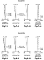
- FIG. 1 is a diagram illustrating the structure of a projection lens in Example 1;
- FIG. 2 is a diagram illustrating the structure of a projection lens in Example 2;
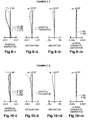
- FIG. 3 is a diagram illustrating the structure of a projection lens in Example 3;
- FIG. 4 is a diagram illustrating the structure of a projection lens in Example 4.
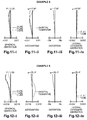
- FIG. 5 is a diagram illustrating the structure of a projection lens in Example 5.
- FIG. 6 is a diagram illustrating the structure of a projection lens in Example 6;
- FIG. 7 - i is a diagram illustrating the spherical aberration of the projection lens in Example 1 (72.0 times magnification);
- FIG. 7 - ii is a diagram illustrating the astigmatism of the projection lens in Example 1 (72.0 times magnification);
- FIG. 7 - iii is a diagram illustrating the distortion of the projection lens in Example 1 (72.0 times magnification);
- FIG. 7 - iv is a diagram illustrating the lateral chromatic aberration of the projection lens in Example 1 (72.0 times magnification);
- FIG. 8 - i is a diagram illustrating the spherical aberration of the projection lens in Example 2 (72.0 times magnification);
- FIG. 8 - ii is a diagram illustrating the astigmatism of the projection lens in Example 2 (72.0 times magnification);
- FIG. 8 - iii is a diagram illustrating the distortion of the projection lens in Example 2 (72.0 times magnification);
- FIG. 8 - iv is a diagram illustrating the lateral chromatic aberration of the projection lens in Example 2 (72.0 times magnification);
- FIG. 9 - i is a diagram illustrating the spherical aberration of the projection lens in Example 3 (72.0 times magnification);
- FIG. 9 - ii is a diagram illustrating the astigmatism of the projection lens in Example 3 (72.0 times magnification);
- FIG. 9 - iii is a diagram illustrating the distortion of the projection lens in Example 3 (72.0 times magnification);
- FIG. 9 - iv is a diagram illustrating the lateral chromatic aberration of the projection lens in Example 3 (72.0 times magnification);
- FIG. 10 - i is a diagram illustrating the spherical aberration of the projection lens in Example 4 (72.0 times magnification);
- FIG. 10 - ii is a diagram illustrating the astigmatism of the projection lens in Example 4 (72.0 times magnification);
- FIG. 10 - iii is a diagram illustrating the distortion of the projection lens in Example 4 (72.0 times magnification);
- FIG. 10 - iv is a diagram illustrating the lateral chromatic aberration of the projection lens in Example 4 (72.0 times magnification);
- FIG. 11 - i is a diagram illustrating the spherical aberration of the projection lens in Example 5 (72.0 times magnification);
- FIG. 11 - ii is a diagram illustrating the astigmatism of the projection lens in Example 5 (72.0 times magnification);
- FIG. 11 - iii is a diagram illustrating the distortion of the projection lens in Example 5 (72.0 times magnification);
- FIG. 11 - iv is a diagram illustrating the lateral chromatic aberration of the projection lens in Example 5 (72.0 times magnification);
- FIG. 12 - i is a diagram illustrating the spherical aberration of the projection lens in Example 6 (72.0 times magnification);
- FIG. 12 - ii is a diagram illustrating the astigmatism of the projection lens in Example 6 (72.0 times magnification);
- FIG. 12 - iii is a diagram illustrating the distortion of the projection lens in Example 6 (72.0 times magnification);
- FIG. 12 - iv is a diagram illustrating the lateral chromatic aberration of the projection lens in Example 6 (72.0 times magnification);
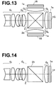
- FIG. 13 is a conceptual diagram of an optical system using a transmissive LCD panel (three panel type for RGB) and a cross dichroic prism in an embodiment of the present invention
- FIG. 14 is a conceptual diagram of an optical system using a reflective LCD panel (single panel type) and a PBS prism in an embodiment of the present invention
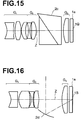
- FIG. 15 is a conceptual diagram of an optical system using a DMD display panel and a TIR prism in an embodiment of the present invention
- FIG. 16 is a conceptual diagram of an optical system using a DMD display panel and a mirror in an embodiment of the present invention.
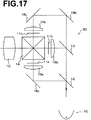
- FIG. 17 is a schematic diagram illustrating the structure of a projection-type display apparatus according to an embodiment of the present invention.
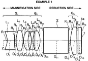
- FIG. 1 is a diagram illustrating the basic structure of a projection lens in Example 1 of the present invention. Embodiments of the present invention will be described using the projection lens illustrated in FIG. 1 as an example.
- the projection lens includes first lens group G 1 having positive refractive power, second lens group G 2 having negative refractive power, and third lens group G 3 having positive refractive power, which are sequentially arranged from the magnification side of the projection lens. Further, the reduction side of the projection lens is telecentric, and at least the following formulas (1) and (2) are satisfied: 0.30 ⁇ d 23 /f 3 ⁇ 0.65 (1); and 10 ⁇
- ff length from the most magnification-side surface in the entire system of the projection lens to a magnification-side focus position of the entire system.
- the formula (1) represents the basic form of the projection lens according to the present embodiment, in which a space for inserting an optical prism is provided between the second lens group G 2 and the third lens group G 3 .
- a space for inserting an optical prism is provided between the second lens group G 2 and the third lens group G 3 .
- the ray separation optical system separates illumination light and projection light from each other, and the ray combination optical system combines rays from plural modulation elements together.
- the back side of the third lens group G 3 can be reduced, it is possible to reduce the external diameter of at least one reduction-side lens.
- the value of d 23 /f 3 exceeds the upper limit defined by the formula (1), the length of the entire lens system becomes too long.
- the value of d 23 /f 3 is lower than lower limit defined by the formula (1), it becomes difficult to insert the ray separation optical system for separating illumination light and projection light from each other, the ray combination optical system for combining rays from plural modulation elements together, or the like.
- the first lens group G 1 is composed of negative lens G 11 (first lens L 1 ), positive lens G 12 (second lens L 2 ), and positive lens G 13 (third lens L 3 ), which are sequentially arranged from the magnification side (please refer to Examples 1, 2, 4 and 5).
- the first lens group G 1 is composed of negative lens G 11 (first lens L 1 ) and positive lens G 12 (second lens L 2 ), which are sequentially arranged from the magnification side (please refer to Examples 3 and 6).
- the second lens group G 2 is composed of negative lens G 21 (fourth lens L 4 in Examples 1, 2, 4 and 5, and third lens L 3 in Examples 3 and 6) and positive lens G 22 (fifth lens L 5 in Examples 1, 2, 4 and 5, and fourth lens L 4 in Examples 3 and 6).
- the third lens group G 3 consists of positive lens G 31 , in other words, the third lens group G 3 is composed of only positive lens G 31 (sixth lens L 6 in Examples 1, 2, 4 and 5, and fifth lens L 5 in Examples 3 and 6).
- illumination light and projection light are separated from each other, or rays from plural spatial modulation elements are combined together in an area between the second lens group G 2 and the third lens group G 3 .
- a stop is arranged on the magnification side of the first lens group G 1 .
- a spot may be arranged between the most-magnification-side lens (lens G 11 ) and a second lens from the magnification side (lens G 12 ).
- a filter 1 a such as an infrared-ray-cut filter or a low-pass filter, is arranged between the third lens group G 3 and an image display plane 1 .
- a glass block (optical prism) 2 is arranged between the second lens group G 2 and the third lens group G 3 .
- the glass block 2 corresponds to a ray separation optical system or a ray combination optical system.
- line Z represents an optical axis.
- glass block (optical prism) 2 arranged between the second lens group G 2 and the third lens group G 3 various types of glass block including those illustrated in FIGS. 13 through 16 may be used for example.
- rays of light are modulated by transmissive liquid crystal panels corresponding to light of three colors, respectively. Further, rays of light of respective colors are output from image display planes 1 B, 1 G, and 1 R of the transmissive liquid crystal panels, respectively, and pass through third lens groups G 3 corresponding to the three colors, respectively. After then, the rays of light of different colors are combined together by a cross dichroic prism 2 a , which is inserted between the third lens groups G 3 and the second lens group G 2 . The combined light passes through the second lens group G 2 and the first lens group G 1 , and is projected onto a screen, which is not illustrated.
- a PBS prism 2 b may be inserted between the third lens group G 3 and the second lens group G 2 .
- the PBS prism 2 b deflects, toward the direction of image display plane 1 P of a reflective liquid crystal display panel, illumination light entering from a direction perpendicular to optical axis Z. Further, the PBS prism 2 b passes modulation light output from the image display plane 1 P of the reflective liquid crystal display panel straight along the optical axis Z. Accordingly, the PBS prism 2 b separates the illumination light and the modulation light from each other. The separated modulation light passes through the second lens group G 2 and the first lens group G 1 , and is projected onto a screen, which is not illustrated.
- a TIR prism 2 c may be inserted between the third lens group G 3 and the second lens group G 2 .
- the TIR prism 2 c deflects, toward the direction of image display plane 1 Q of a DMD display panel, illumination light entering from an oblique lower direction with respect to optical axis Z. Further, the TIR prism 2 c passes modulation light output from the image display plane 1 Q of the DMD display panel travel straight along the optical axis Z. Accordingly, the TIR prism 2 c separates the illumination light and the modulation light from each other. The separated modulation light passes through the second lens group G 2 and the first lens group G 1 , and is projected onto a screen, which is not illustrated.
- a concave mirror 2 d may be inserted, at a position away from optical axis Z, between the third lens group G 3 and the second lens group G 2 .
- the concave mirror 2 d deflects, toward the direction of image display plane 1 S of a DMD display panel, illumination light entering from a direction perpendicular to the optical axis Z.
- the concave mirror 2 d allows modulation light output from the image display plane 1 S of the DMD display panel travel straight along the optical axis Z. Accordingly, the concave mirror 2 d separates the illumination light and the modulation light from each other. The separated modulation light passes through the second lens group G 2 and the first lens group G 1 , and is projected onto a screen, which is not illustrated.
- each aspheric surface is represented by the following equation:
- Z length of a perpendicular from a point on an aspheric surface, the point away from optical axis by distance Y, to flat plane (flat plane perpendicular to the optical axis) in contact with the vertex of the aspheric surface,
- R curvature radius of the aspheric surface in the vicinity of the optical axis
- the formulas (1) and (2) are satisfied. Further, it is desirable that at least one of the following formulas (3) through (7) is satisfied: bf/f 3 ⁇ 0.2 (3); 1.2 ⁇ f 3 /f ⁇ 1.9 (4); 0.4 ⁇ D 12 /f 3 ⁇ 1.1 (5); 0.2 ⁇ f 1 /f ⁇ 1.0 (6); and ⁇ 3.5 ⁇ f 2 /f ⁇ 0.5 (7), where
- D 12 the total length of the first lens group G 1 and the second lens group G 2 in the direction of the optical axis.
- the formula (3) defines the range of a value obtained by dividing the back focus bf in air of the entire system by focal length f 3 of the third lens group G 3 .
- the formula (3) defines the range for reducing the size of the lens group G 3 . In other words, when the value exceeds the upper limit defined by the formula (3), it becomes difficult to reduce the size of the third lens group G 3 .
- the formula (4) defines the range of a value obtained by dividing the focal length f 3 of the third lens group G 3 by the focal length f of the entire system.
- the formula (4) defines a range in which the size of the second lens group G 2 is reducible while correction of aberration, such as image plane correction, is performed in an excellent manner.
- the value exceeds the upper limit defined by the formula (4), the total length of the second lens group G 2 becomes too long, and it becomes difficult to reduce the size of the lens system.
- the value is lower than the lower limit defined by the formula (4), the power of the third lens group G 3 becomes too strong, and it becomes difficult to perform correction of aberration, such as image plane correction.
- the formula (5) defines the range of a value obtained by dividing the total length D 12 of the first lens group G 1 and the second lens group G 2 in the direction of the optical axis by the focal length f 3 of the third lens group G 3 .
- the formula (5) is satisfied, the total length D 12 of the first lens group G 1 and the second lens group G 2 does not become too short, and aberrations are corrected in an excellent manner. Further, the total length D 12 of the first lens group G 1 and the second lens group G 2 does not become too long. Therefore, it is possible to reduce the size of the lens system. In other words, when the value exceeds the upper limit defined by the formula (5), the total length of the first lens group G 1 and the second lens group G 2 becomes too long. Further, when the value is lower than the lower limit defined by the formula (5), the total length of the first lens group G 1 and the second lens group G 2 becomes too short, and it becomes difficult to perform correction of aberration, such as image plane correction.
- the formula (6) defines the range of a value obtained by dividing the focal length f 1 of the first lens group G 1 by the focal length f of the entire system.
- the formula (6) defines a range in which the size of the first lens group G 1 is reducible while chromatic aberration is corrected in an excellent manner.
- the value exceeds the upper limit defined by the formula (6), the total length of the first lens group G 1 becomes too long, and it becomes difficult to reduce the size of the entire system.
- the value is lower than the lower limit defined by the formula (6), the power of the first lens group G 1 becomes too strong, and it becomes difficult to correct aberrations, such as chromatic aberration.
- the formula (7) defines the range of a value obtained by dividing the focal length f 2 of the second lens group G 2 by the focal length f of the entire system.
- the formula (7) defines a range in which the size of the second lens group G 2 is reducible while various kinds of aberration are corrected in an excellent manner. In other words, when the value exceeds the upper limit defined by the formula (7), the power of the second lens group G 2 becomes too strong, and it becomes difficult to correct various kinds of aberration. When the value is lower than the lower limit defined by the formula (7), the total length of the second lens group G 2 becomes too long, and it becomes difficult to reduce size of the entire system.
- a projection-type display apparatus 30 illustrated in FIG. 17 includes transmissive liquid crystal panels 11 a through 11 c , as light valves. Further, the projection-type display apparatus 30 uses, as a projection lens 10 , a projection lens according to the aforementioned embodiments of the present invention.
- a light source 15 and a dichroic mirror 12 are not illustrated. White light is output from the light source 15 , and enters, through an illumination optical unit, liquid crystal panels 11 a through 11 c , which correspond to rays of light of three colors (G light, B light and R light), respectively, and is optically modulated.
- the projection-type display apparatus 30 includes condenser lenses 16 a through 16 c and total reflection mirrors 18 a through 18 c.
- the projection-type display apparatus 30 uses the projection lens in which the size of the entire system has been reduced. Therefore, it is possible to reduce the whole size of the projection-type display apparatus 30 .
- the projection lens of the present invention uses, as light valves, transmissive liquid crystal display panels.
- the projection lens of the present invention may be used, as a projection lens, in a apparatus using a reflective liquid crystal display panel or other optical modulation means, such as a DMD.
- a projection lens in Example 1 is structured as illustrated in FIG. 1 .
- the projection lens is composed of first lens group G 1 , second lens group G 2 , and third lens group G 3 , which are sequentially arranged from the magnification side of the projection lens.
- the first lens group G 1 is composed of first lens L 1 , second lens L 2 and third lens L 3 , which are sequentially arranged from the magnification side. Both surfaces of the first lens L 1 are aspheric (double concave (concave-concave) in the vicinity of the optical axis), and the first lens L 1 is made of plastic.
- the second lens L 2 is a double convex (convex-convex) lens made of glass.
- the third lens L 3 is a positive meniscus lens having a convex surface facing the magnification side.
- the second lens group G 2 is composed of fourth lens L 4 and fifth lens L 5 .
- the fourth lens L 4 is a double concave lens
- the fifth lens L 5 is a double convex lens.
- the third lens group G 3 is composed of sixth lens L 6 , which is a plano-convex lens having a convex surface facing the magnification side.
- a wide space (sufficiently long distance) is maintained between the second lens group G 2 and the third lens group G 3 , and a color combination prism (or a ray separation prism) 2 is arranged in the space between the second lens group G 2 and the third lens group G 3 .
- the space between the second lens group G 2 and the third lens group G 3 is set so as to satisfy the range defined by the formula (1). Specifically, the value of d 23 /f 3 is 0.43 in Example 1.
- both surfaces of the first lens L 1 in Example 1 are aspheric surfaces represented by the aforementioned aspheric surface equation (Equation 1).
- Table 1 shows data about Example 1.
- Table 1 shows the curvature radius R of each lens surface (normalized by assuming the focal length of the entire lens system to be 1.00; same in the following tables), the center thickness D of each lens and air space D between lenses (normalized in a manner similar to the curvature radius R, same in the following tables), and refractive index N d and Abbe number ⁇ d of each lens for d-line.
- Table 1 and Tables 3, 5, 7, 9 and 11, which will be described later surface numbers for each sign R, D, N d , and ⁇ d sequentially increase from the magnification side.
- focal length f of the entire system is shown at the top of Table 1, and Tables 3, 5, 7, 9 and 11, which will be described later.
- both surfaces of the first lens L 1 are aspheric.
- Table 2 shows aspheric coefficients K, A 3 , A 4 , A 5 , A 6 , A 7 , A 8 , A 9 , A 10 , A 11 , and A 12 in the equation representing the aspheric surfaces for these aspheric surfaces.
- FIG. 7 - i through 7 - iv are diagrams illustrating aberrations in Example 1.
- FIG. 7 - i illustrates spherical aberration in Example 1
- FIG. 7 - ii illustrates astigmatism in Example 1
- FIG. 7 - iii illustrates distortion in Example 1
- FIG. 7 - iv illustrates lateral chromatic aberration in Example 1 (72.0 times magnification).
- FIG. 7 - i and FIGS. 8 - i , 9 - i , 10 - i , 11 - i and 12 - i , which will be described later, spherical aberrations for d-line, F-line and C-line are illustrated.
- FIG. 8 - i illustratespherical aberrations for d-line, F-line and C-line are illustrated.
- FIG. 7 - ii , and FIGS. 8 - ii , 9 - ii , 10 - ii , 11 - ii and 12 - ii which will be described later, aberrations (astigmatism) with respect to sagittal image planes and aberrations with respect to tangential image planes are illustrated.
- FIG. 7 - iv , and FIGS. 8 - iv , 9 - iv , 10 - iv , 11 - iv and 12 - iv which will be described later, lateral chromatic aberrations of F-line and C-line with respect to d-line are illustrated.
- each aberration is corrected in an excellent manner in the projection lens of Example 1.
- the projection lens of Example 1 satisfies the formulas (1) through (7), formulas (1′) through (7′) and formulas (2′′), (6′′) and (7′′).
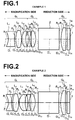
- FIG. 2 is a schematic diagram illustrating the structure of a projection lens in Example 2.
- the projection lens in Example 2 is structured in a substantially similar manner to Example 1.
- both surfaces of the third lens L 3 in the first lens group G 1 are aspheric, and the third lens L 3 is made of plastic.
- the fifth lens L 5 in the second lens group G 2 is a positive meniscus lens having a convex surface facing the reduction side of the projection lens.
- a wide space is maintained between the second lens group G 2 and the third lens group G 3 , and a color combination prism (or a ray separation prism) 2 is arranged in the space between the second lens group G 2 and the third lens group G 3 .
- the space between the second lens group G 2 and the third lens group G 3 is set so as to satisfy the range defined by the formula (1). Specifically, the value of d 23 /f 3 is 0.43 in Example 2.
- Table 3 shows data about Example 2.
- Table 3 shows the curvature radius R of each lens surface, the center thickness D of each lens and air space D between lenses, and refractive index N d and Abbe number ⁇ d of each lens for d-line.
- both surfaces of the first lens L 1 and both surfaces of the third lens L 3 are aspheric.
- Table 4 shows aspheric coefficients K, A 3 , A 4 , A 5 , A 6 , A 7 , A 8 , A 9 , A 10 , A 11 , and A 12 in the equation representing aspheric surfaces for these aspheric surfaces.
- FIG. 8 - i through 8 - iv are diagrams illustrating aberrations in Example 2.
- FIG. 8 - i illustrates spherical aberration in Example 2
- FIG. 8 - ii illustrates astigmatism in Example 2
- FIG. 8 - iii illustrates distortion in Example 2
- FIG. 8 - iv illustrates lateral chromatic aberration in Example 2 (72.0 times magnification).
- each aberration is corrected in an excellent manner in the projection lens of Example 2.
- the projection lens in Example 2 satisfies the formulas (1) through (7), formulas (1′) through (7′) and formulas (2′′), (6′′) and (7′′).
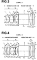
- FIG. 3 is a schematic diagram illustrating the structure of a projection lens in Example 3.
- the projection lens in Example 3 is structured in a similar manner to Example 1.
- Example 3 greatly differs from Example 1 in that the projection lens of Example 3 is composed of five lenses.
- the projection lens of Example 3 is composed of first lens group G 1 , second lens group G 2 and third lens group G 3 , which are sequentially arranged from the magnification side.
- the first lens group G 1 is composed of first lens L 1 and second lens L 2 , which are sequentially arranged from the magnification side. Both surfaces of the first lens L 1 are aspheric, and the first lens L 1 is made of plastic (negative meniscus lens shape having a concave surface facing the magnification side in the vicinity of the optical axis).
- Both surfaces of the second lens L 2 are aspheric, and the second lens L 2 is made of plastic (double convex lens shape in the vicinity of the optical axis).
- the second lens group G 2 is composed of third lens L 3 and fourth lens L 4 , which are sequentially arranged from the magnification side.
- the third lens L 3 is a double concave lens
- the fourth lens L 4 is a positive meniscus lens having a convex surface facing the reduction side.
- the third lens group G 3 is composed of fifth lens L 5 , which is a plano-convex lens having a convex surface facing the magnification side.
- a wide space is maintained between the second lens group G 2 and the third lens group G 3 , and a color combination prism (or a ray separation prism) 2 is arranged in the space between the second lens group G 2 and the third lens group G 3 .
- the space between the second lens group G 2 and the third lens group G 3 is set so as to satisfy the range defined by the formula (1). Specifically, the value of d 23 /f 3 is 0.46 in Example 3.
- Table 5 shows data about Example 3.
- Table 5 shows the curvature radius R of each lens surface, the center thickness D of each lens and air space D between lenses, and refractive index N d and Abbe number ⁇ d of each lens for d-line.
- both surfaces of the first lens L 1 and both surfaces of the second lens L 2 are aspheric.
- Table 6 shows aspheric coefficients K, A 3 , A 4 , A 5 , A 6 , A 7 , A 8 , A 9 , A 10 , A 11 , and A 12 in the equation representing the aspheric surfaces for these aspheric surfaces.
- FIG. 9 - i through 9 - iv are diagrams illustrating aberrations in Example 3.
- FIG. 9 - i illustrates spherical aberration in Example 3
- FIG. 9 - ii illustrates astigmatism in Example 3
- FIG. 9 - iii illustrates distortion in Example 3
- FIG. 9 - iv illustrates lateral chromatic aberration in Example 3 (72.0 times magnification).
- each aberration is corrected in an excellent manner in the projection lens of Example 3.
- the projection lens in Example 3 satisfies the formulas (1) through (7), formulas (1′) through (7′) and formulas (6′′) and (7′′).
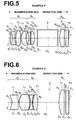
- FIG. 4 is a schematic diagram illustrating the structure of a projection lens in Example 4.
- the projection lens in Example 4 is structured in a substantially similar manner to Example 1.
- Example 4 mainly differs from Example 1 in that both surfaces of the third lens L 3 in the first lens group G 1 are aspheric, and the third lens L 3 is made of plastic (positive meniscus lens shape having a convex surface facing the magnification side in the vicinity of the optical axis).
- a wide space is maintained between the second lens group G 2 and the third lens group G 3 , and a color combination prism (or a ray separation prism) 2 is arranged in the space between the second lens group G 2 and the third lens group G 3 .
- the space between the second lens group G 2 and the third lens group G 3 is set so as to satisfy the range defined by the formula (1). Specifically, the value of d 23 /f 3 is 0.49 in Example 4.
- Table 7 shows data about Example 4.
- Table 7 shows the curvature radius R of each lens surface, the center thickness D of each lens and air space D between lenses, and refractive index N d and Abbe number ⁇ d of each lens for d-line.
- both surfaces of the first lens L 1 and both surfaces of the third lens L 3 are aspheric.
- Table 8 shows aspheric coefficients K, A 3 /A 4 , A 5 , A 6 , A 7 , A 8 , A 9 , A 10 , A 11 , and A 12 in the equation representing aspheric surfaces for these aspheric surfaces.
- FIG. 10 - i through 10 - iv are diagrams illustrating aberrations in Example 4.
- FIG. 10 - i illustrates spherical aberration in Example 4
- FIG. 10 - ii illustrates astigmatism in Example 4
- FIG. 10 - iii illustrates distortion in Example 4
- FIG. 10 - iv illustrates lateral chromatic aberration in Example 4 (72.0 times magnification).
- each aberration is corrected in an excellent manner in the projection lens of Example 4.
- the projection lens in Example 4 satisfies the formulas (1) through (7), formulas (1′) through (7′) and formulas (2′′), (6′′) and (7′′).
- FIG. 5 is a schematic diagram illustrating the structure of a projection lens in Example 5.
- the projection lens in Example 5 is structured in a substantially similar manner to Example 2.
- Example 5 differs from Example 2 in that a stop 3 (a mask may be provided instead of the stop) is provided on the magnification side of the first lens L 1 .
- a wide space is maintained between the second lens group G 2 and the third lens group G 3 , and a color combination prism (or a ray separation prism) 2 is arranged in the space between the second lens group G 2 and the third lens group G 3 .
- the space between the second lens group G 2 and the third lens group G 3 is set so as to satisfy the range defined by the formula (1). Specifically, the value of d 23 /f 3 is 0.50 in Example 5.
- Table 9 shows data about Example 5.
- Table 9 shows the curvature radius R of each lens surface, the center thickness D of each lens and air space D between lenses, and refractive index N d and Abbe number ⁇ d of each lens for d-line.
- both surfaces of the first lens L 1 and both surfaces of the third lens L 3 are aspheric.
- Table 10 shows aspheric coefficients K, A 3 , A 4 , A 5 , A 6 , A 7 , A 8 , A 9 , A 10 , A 11 , and A 12 in the equation representing aspheric surfaces for these aspheric surfaces.
- FIG. 11 - i through 11 - iv are diagrams illustrating aberrations in Example 5.
- FIG. 11 - i illustrates spherical aberration in Example 5
- FIG. 11 - ii illustrates astigmatism in Example 5
- FIG. 11 - iii illustrates distortion in Example 5
- FIG. 11 - iv illustrates lateral chromatic aberration in Example 5 (72.0 times magnification).
- each aberration is corrected in an excellent manner in the projection lens of Example 5.
- the projection lens in Example 5 satisfies the formulas (1) through (7), formulas (1′) through (7′) and formulas (2′′), (6′′) and (7′′).
- FIG. 6 is a schematic diagram illustrating the structure of a projection lens in Example 6.
- the projection lens in Example 6 is composed of five lenses in a manner similar to Example 3.
- Example 6 mainly differs from Example 3 in that both surfaces of the fourth lens L 4 in the second lens group G 2 are aspheric, and the fourth lens L 4 is made of plastic (double convex lens shape in the vicinity of the optical axis), and that an optical prism is not arranged between the second lens group G 2 and the third lens group G 3 .
- an optical prism for separating/combining rays may be inserted between the second lens group G 2 and the third lens group G 3 .
- a reflection mirror ( 2 d ) for separating rays may be arranged, as illustrated in FIG. 16 .
- the space between the second lens group G 2 and the third lens group G 3 is set so as to satisfy the range defined by the formula (1). Specifically, the value of d 23 /f 3 is 0.52 in Example 6.
- both surfaces of the first lens L 1 and both surfaces of the second lens L 2 and both surfaces of the fourth lens L 4 are aspheric.
- Table 12 shows aspheric coefficients K, A 4 , A 5 , A 6 , A 7 , A 8 , A 9 , A 10 , A 11 , and A 12 in the equation representing aspheric surfaces for these aspheric surfaces.
- FIG. 12 - i through 12 - iv are diagrams illustrating aberrations in Example 6.
- FIG. 12 - i illustrates spherical aberration in Example 6, and
- FIG. 12 - ii illustrates astigmatism in Example 6, and
- FIG. 12 - iii illustrates distortion in Example 6, and
- FIG. 12 - iv illustrates lateral chromatic aberration in Example 6 (72.0 times magnification).
- each aberration is corrected in an excellent manner in the projection lens of Example 6.
- the projection lens in Example 5 satisfies the formulas (1) through (7), formulas (1′) through (7′) and formulas (6′′) and (7′′).
- the projection optical system (projection lens) of the present invention and a projection-type display apparatus using the projection optical system of the present invention are not limited to the aforementioned examples.
- Various modifications are possible without departing from the gist of the present invention.
- the shape of each lens, the number of lenses constituting each lens group, the position of arrangement of each lens may be set in an appropriate manner.
Landscapes
- Physics & Mathematics (AREA)
- General Physics & Mathematics (AREA)
- Optics & Photonics (AREA)
- Lenses (AREA)
- Projection Apparatus (AREA)
Applications Claiming Priority (2)
| Application Number | Priority Date | Filing Date | Title |
|---|---|---|---|
| JP2010-078038 | 2010-03-30 | ||
| JP2010078038A JP5442515B2 (ja) | 2010-03-30 | 2010-03-30 | 投写用レンズおよびこれを用いた投写型表示装置 |
Publications (2)
| Publication Number | Publication Date |
|---|---|
| US20110242685A1 US20110242685A1 (en) | 2011-10-06 |
| US8508855B2 true US8508855B2 (en) | 2013-08-13 |
Family
ID=44709404
Family Applications (1)
| Application Number | Title | Priority Date | Filing Date |
|---|---|---|---|
| US13/075,594 Active 2032-02-16 US8508855B2 (en) | 2010-03-30 | 2011-03-30 | Projection lens and projection-type display apparatus using the lens |
Country Status (3)
| Country | Link |
|---|---|
| US (1) | US8508855B2 (zh) |
| JP (1) | JP5442515B2 (zh) |
| CN (1) | CN202119963U (zh) |
Cited By (3)
| Publication number | Priority date | Publication date | Assignee | Title |
|---|---|---|---|---|
| US20180059380A1 (en) * | 2016-08-30 | 2018-03-01 | Fujifilm Corporation | Wide-angle lens, projection display device, and imaging apparatus |
| US10175493B1 (en) | 2017-07-31 | 2019-01-08 | Largan Precision Co., Ltd. | Projection lens system, projection apparatus, sensing module and electronic device |
| RU200847U1 (ru) * | 2019-12-24 | 2020-11-13 | Акционерное общество "НПО "Орион" | Проекционный объектив для средней ИК области спектра |
Families Citing this family (8)
| Publication number | Priority date | Publication date | Assignee | Title |
|---|---|---|---|---|
| JP5259503B2 (ja) * | 2009-06-16 | 2013-08-07 | 富士フイルム株式会社 | 投写光学系、およびこれを用いた投写型表示装置 |
| CN103370645B (zh) | 2011-01-31 | 2016-09-14 | 富士胶片株式会社 | 投影镜头和投影显示设备 |
| JP5823258B2 (ja) * | 2011-11-02 | 2015-11-25 | 日東光学株式会社 | 投射用レンズシステムおよび投影装置 |
| TWI597519B (zh) * | 2015-12-28 | 2017-09-01 | 鴻海精密工業股份有限公司 | 變焦鏡頭及應用該變焦鏡頭的取像裝置 |
| TWI721211B (zh) * | 2017-09-08 | 2021-03-11 | 揚明光學股份有限公司 | 鏡頭及包含其之投影裝置 |
| CN109445067B (zh) * | 2018-11-23 | 2020-05-29 | 江西联创电子有限公司 | 光学成像镜头及成像设备 |
| CN110196487B (zh) * | 2019-06-17 | 2021-01-12 | 上海帆声图像科技有限公司 | 一种远心镜头 |
| CN110568586A (zh) * | 2019-08-30 | 2019-12-13 | 歌尔股份有限公司 | 投影镜头及投影设备 |
Citations (4)
| Publication number | Priority date | Publication date | Assignee | Title |
|---|---|---|---|---|
| US6038078A (en) * | 1998-08-24 | 2000-03-14 | Fuji Photo Optical Co., Ltd. | Projection lens |
| JP2003315675A (ja) | 2002-04-22 | 2003-11-06 | Nitto Kogaku Kk | 投写レンズシステムおよびプロジェクタ装置 |
| JP2005215310A (ja) | 2004-01-29 | 2005-08-11 | Casio Comput Co Ltd | 投影レンズ |
| US7859763B2 (en) * | 2009-04-10 | 2010-12-28 | Young Optics Inc. | Fixed-focus lens |
Family Cites Families (3)
| Publication number | Priority date | Publication date | Assignee | Title |
|---|---|---|---|---|
| JPS62237416A (ja) * | 1986-04-08 | 1987-10-17 | Minolta Camera Co Ltd | 有限距離用ズ−ムレンズ系 |
| JP2004212729A (ja) * | 2003-01-06 | 2004-07-29 | Seiko Epson Corp | プロジェクター |
| JP2009047722A (ja) * | 2007-08-13 | 2009-03-05 | Konica Minolta Opto Inc | 変倍光学系、撮像装置およびデジタル機器 |
-
2010
- 2010-03-30 JP JP2010078038A patent/JP5442515B2/ja active Active
-
2011
- 2011-03-30 CN CN2011200946212U patent/CN202119963U/zh not_active Expired - Lifetime
- 2011-03-30 US US13/075,594 patent/US8508855B2/en active Active
Patent Citations (4)
| Publication number | Priority date | Publication date | Assignee | Title |
|---|---|---|---|---|
| US6038078A (en) * | 1998-08-24 | 2000-03-14 | Fuji Photo Optical Co., Ltd. | Projection lens |
| JP2003315675A (ja) | 2002-04-22 | 2003-11-06 | Nitto Kogaku Kk | 投写レンズシステムおよびプロジェクタ装置 |
| JP2005215310A (ja) | 2004-01-29 | 2005-08-11 | Casio Comput Co Ltd | 投影レンズ |
| US7859763B2 (en) * | 2009-04-10 | 2010-12-28 | Young Optics Inc. | Fixed-focus lens |
Cited By (4)
| Publication number | Priority date | Publication date | Assignee | Title |
|---|---|---|---|---|
| US20180059380A1 (en) * | 2016-08-30 | 2018-03-01 | Fujifilm Corporation | Wide-angle lens, projection display device, and imaging apparatus |
| US10082650B2 (en) * | 2016-08-30 | 2018-09-25 | Fujifilm Corporation | Wide-angle lens, projection display device, and imaging apparatus |
| US10175493B1 (en) | 2017-07-31 | 2019-01-08 | Largan Precision Co., Ltd. | Projection lens system, projection apparatus, sensing module and electronic device |
| RU200847U1 (ru) * | 2019-12-24 | 2020-11-13 | Акционерное общество "НПО "Орион" | Проекционный объектив для средней ИК области спектра |
Also Published As
| Publication number | Publication date |
|---|---|
| JP5442515B2 (ja) | 2014-03-12 |
| CN202119963U (zh) | 2012-01-18 |
| US20110242685A1 (en) | 2011-10-06 |
| JP2011209564A (ja) | 2011-10-20 |
Similar Documents
| Publication | Publication Date | Title |
|---|---|---|
| US10890742B2 (en) | Projection optical system and projection type display device | |
| US8508855B2 (en) | Projection lens and projection-type display apparatus using the lens | |
| US10620413B2 (en) | Projection optical system and projection type display device | |
| US9869849B2 (en) | Projection optical system and projection type display device | |
| US8320048B2 (en) | Projection lens and projection-type display apparatus using the lens | |
| US8508853B2 (en) | Projection lens and projection-type display apparatus | |
| US10338356B2 (en) | Projection optical system and projection type display device | |
| US8830591B2 (en) | Projection lens and projection display apparatus | |
| US8213091B2 (en) | Wide-angle projection zoom lens and projection display device | |
| US8116010B2 (en) | Projection variable focus lens and projection display device | |
| US8179606B2 (en) | Zoom lens for projection and projection-type display device | |
| US9557538B2 (en) | Projection zoom lens and projection type display device | |
| US20110157716A1 (en) | Zoom lens for projection and projection-type display apparatus | |
| US8270091B2 (en) | Projection variable focusing lens and projection display device | |
| WO2012114756A1 (ja) | 投写用ズームレンズおよび投写型表示装置 | |
| JP2019035873A (ja) | 投写用光学系及び投写型表示装置 | |
| US9541743B2 (en) | Projection zoom lens and projection type display device | |
| US20140022519A1 (en) | Projection optical system and projection display apparatus | |
| US10386618B2 (en) | Projection optical system and projection type display device | |
| US20110007402A1 (en) | Projection variable focus lens and projection display device | |
| US8199419B2 (en) | Projection variable focusing lens and projection display device | |
| US20160085060A1 (en) | Projection zoom lens and projection type display device | |
| US10838179B2 (en) | Wide-angle lens, projection lens, relay lens, projection-type display apparatus, and relay lens unit |
Legal Events
| Date | Code | Title | Description |
|---|---|---|---|
| AS | Assignment |
Owner name: FUJIFILM CORPORATION, JAPAN Free format text: ASSIGNMENT OF ASSIGNORS INTEREST;ASSIGNOR:YAMAMOTO, CHIKARA;REEL/FRAME:026144/0747 Effective date: 20110315 |
|
| STCF | Information on status: patent grant |
Free format text: PATENTED CASE |
|
| FEPP | Fee payment procedure |
Free format text: PAYOR NUMBER ASSIGNED (ORIGINAL EVENT CODE: ASPN); ENTITY STATUS OF PATENT OWNER: LARGE ENTITY |
|
| FPAY | Fee payment |
Year of fee payment: 4 |
|
| MAFP | Maintenance fee payment |
Free format text: PAYMENT OF MAINTENANCE FEE, 8TH YEAR, LARGE ENTITY (ORIGINAL EVENT CODE: M1552); ENTITY STATUS OF PATENT OWNER: LARGE ENTITY Year of fee payment: 8 |