US8457548B2 - Relay device, communication system and communication method - Google Patents
Relay device, communication system and communication method Download PDFInfo
- Publication number
- US8457548B2 US8457548B2 US12/999,504 US99950409A US8457548B2 US 8457548 B2 US8457548 B2 US 8457548B2 US 99950409 A US99950409 A US 99950409A US 8457548 B2 US8457548 B2 US 8457548B2
- Authority
- US
- United States
- Prior art keywords
- data
- relay device
- received
- numerical information
- communication
- Prior art date
- Legal status (The legal status is an assumption and is not a legal conclusion. Google has not performed a legal analysis and makes no representation as to the accuracy of the status listed.)
- Expired - Fee Related, expires
Links
Images


Classifications
-
- H—ELECTRICITY
- H04—ELECTRIC COMMUNICATION TECHNIQUE
- H04L—TRANSMISSION OF DIGITAL INFORMATION, e.g. TELEGRAPHIC COMMUNICATION
- H04L12/00—Data switching networks
- H04L12/28—Data switching networks characterised by path configuration, e.g. LAN [Local Area Networks] or WAN [Wide Area Networks]
- H04L12/46—Interconnection of networks
- H04L12/4604—LAN interconnection over a backbone network, e.g. Internet, Frame Relay
- H04L12/462—LAN interconnection over a bridge based backbone
- H04L12/4625—Single bridge functionality, e.g. connection of two networks over a single bridge
-
- H—ELECTRICITY
- H04—ELECTRIC COMMUNICATION TECHNIQUE
- H04L—TRANSMISSION OF DIGITAL INFORMATION, e.g. TELEGRAPHIC COMMUNICATION
- H04L12/00—Data switching networks
- H04L12/28—Data switching networks characterised by path configuration, e.g. LAN [Local Area Networks] or WAN [Wide Area Networks]
- H04L12/40—Bus networks
- H04L12/40006—Architecture of a communication node
- H04L12/40013—Details regarding a bus controller
-
- H—ELECTRICITY
- H04—ELECTRIC COMMUNICATION TECHNIQUE
- H04L—TRANSMISSION OF DIGITAL INFORMATION, e.g. TELEGRAPHIC COMMUNICATION
- H04L12/00—Data switching networks
- H04L12/28—Data switching networks characterised by path configuration, e.g. LAN [Local Area Networks] or WAN [Wide Area Networks]
- H04L12/40—Bus networks
- H04L12/403—Bus networks with centralised control, e.g. polling
- H04L12/4035—Bus networks with centralised control, e.g. polling in which slots of a TDMA packet structure are assigned based on a contention resolution carried out at a master unit
-
- H—ELECTRICITY
- H04—ELECTRIC COMMUNICATION TECHNIQUE
- H04L—TRANSMISSION OF DIGITAL INFORMATION, e.g. TELEGRAPHIC COMMUNICATION
- H04L12/00—Data switching networks
- H04L12/28—Data switching networks characterised by path configuration, e.g. LAN [Local Area Networks] or WAN [Wide Area Networks]
- H04L12/40—Bus networks
- H04L2012/40267—Bus for use in transportation systems
- H04L2012/40273—Bus for use in transportation systems the transportation system being a vehicle
Definitions
- the present invention relates to a communication system in which data is transmitted and received among a plurality of communication devices. More specifically, the present invention relates to a relay device relaying transmission and reception of data among communication devices, the relay device being able to shorten time required for exchange of data when data is exchanged between a plurality of relay devices while further maintaining the data held by the relay devices to be identical, and also relates to a communication system including the relay device and to a communication method.
- each communication device As the function of each communication device is specialized while the number of functions to be performed by each communication device is increased, the number and types of communication devices connected to a communication medium are also increased. Moreover, various functions are expected for the system, which generates the need for each communication device to share data and cooperate with one another, increasing the amount of data to be transmitted.
- Increase of the amount of data transmitted and received through a communication line causes delay or loss of data as a result of collision. Significant delay or loss of data may be fatal to the driver assistant function such as brake control by ECU.
- communication devices are divided into a plurality of groups and a device having a database relays the transmission and reception of data between different groups to share the database, which can reduce delay.
- a device having a database relays transmission and reception of data between communication devices in different groups to reduce delay.
- An object of the invention is to provide a relay device that, when data is exchanged between relay devices having databases, can reduce the amount of communication by transmitting and receiving only appropriately-combined numerical information among data including a pair of identification information and numerical information corresponding to the identification information, and can also maintain the databases in the relay devices to be identical by not updating a database unless a notice of determination is received at each device, and to provide a communication system including the relay device and a communication method.
- a relay device is a relay device connected to an external device periodically transmitting and receiving data including numerical information and identification information of the numerical information, the relay device comprising first communication means for performing transmission and reception of data with the external device and means for storing data in a database, and transmitting data read out from the database to the external device through said first communication means to relay transmission and reception of data between external devices, characterized by further comprising: second communication means for communicating with another relay device; means for storing, each time data is received from the external device, numerical information of the received one or more data in a first buffer with respect to said database; means for reading out the numerical information stored in said first buffer and creating a data frame including the numerical information for a certain period of time; means for transmitting the created data frame through said second communication means; means for storing, when a data frame is received from another relay device, the received data frame or the numerical information included in the data frame in a second buffer with respect to said database; update means for updating the numerical information of data in the database with the numerical information in said first and second buffers
- a relay device is characterized in that, when it is judged that the notice of determination is not received, said update means updates at a time when transmission information indicating that said notice of determination is transmitted is received from another relay device.
- a relay device is a relay device connected to an external device periodically transmitting and receiving data including numerical information and identification information of the numerical information, the relay device comprising first communication means for performing transmission and reception of data with the external device and means for storing data in a database, and transmitting data read out from the database to the external device through said first communication means to relay transmission and reception of data between external devices, characterized by further comprising: second communication means for communicating with another relay device; means for storing, each time data is received from the external device, numerical information of the received one or more data in a first buffer with respect to said database; means for reading out the numerical information stored in said first buffer and creating a data frame including the numerical information for a certain period of time; means for transmitting the created data frame through said second communication means to another relay device; means for storing, when a data frame is received from another relay device, the received data frame or the numerical information included in the data frame in a second buffer with respect to said database; judgment means for judging whether or not data to be stored in the database is to be determined
- a relay device is, in the third aspect, characterized by further comprising notice information transmitting means for transmitting, through said second communication means, notice information indicating whether or not said notice of determination was transmitted in a preceding period, wherein when said judgment means judges that the data is to be determined, said notice information transmitting means transmits, in a subsequent period, notice information indicating that said notice of determination is transmitted.
- a relay device is, in the third aspect, characterized in that, when said judgment means judges that the data is not to be determined, said notice information transmitting means transmits, in the subsequent period, notice information indicating that said notice of determination is not transmitted, and a data frame created in the preceding period is retransmitted.
- a communication system is a communication system comprising a plurality of communication device groups each constructed by a plurality of communication devices periodically transmitting and receiving data including numerical information and identification information of the numerical information, and a plurality of relay devices connected with each other to relay transmission and reception of data among the communication devices, one or more of the relay devices being connected to each of the plurality of communication device groups, each relay device including: first communication means for performing transmission and reception of data with the communication device; means for storing data in a database; and means for transmitting data read out from the database to the communication device through said first communication means, characterized in that each of the relay devices includes: second communication means for communicating with another relay device; means for storing, each time data is received from the communication device connected to the relay device, numerical information of the received one or more data in a first buffer with respect to said database; means for reading out the numerical information stored in said first buffer and creating a data frame including the numerical information for a certain period of time; means for transmitting the created data frame through said second communication means to another relay device;
- a communication system is, in the sixth aspect, characterized in that the relay devices are connected in series, and said specified relay device is a relay device located at one end in the relay devices.
- a communication system is, in the seventh aspect, characterized in that the relay device located at an end in the relay devices opposite from said specified relay device waits transmission of the created data frame until data frames transmitted from all the other relay devices are received, and the other relay devices includes means for transferring, when a data frame is received from one of the neighboring relay devices through said second communication means, the data frame to another one of the neighboring relay devices.
- a communication system is, in the seventh or eighth aspect, characterized in that the judgment means of said specified relay device judges that data is to be determined, when data frames are received from all the other relay devices.
- a communication method is a communication method to be performed by a plurality of relay devices connected with each other, one or more of the relay devices being connected to each of a plurality of communication device groups constructed by a plurality of communication devices periodically transmitting and receiving data including numerical information and identification information of the numerical information, each of the relay devices receiving data from the communication device, storing data in a database, transmitting data read out from said database to the communication device, to relay transmission and reception of data between the communication devices, characterized in that each of the relay devices stores, each time data is received from the communication device connected to the relay device, numerical information of the received one or more data in a first buffer with respect to said database; reads out the numerical information stored in said first buffer and creates a data frame including the numerical information for a certain period of time; transmits the created data frame to another relay device; receives a data frame transmitted from another relay device; and stores the received data frame or numerical information included in the data frame in a second buffer with respect to said database, and that a specified relay device among
- each of the relay devices transmits and receives a data frame including numerical information through the second communication means different from the first communication means for communicating with the external device, to exchange data.
- the information length indicating identification information becomes longer.
- the total information length of identification information is further increased in accordance with the number of data exchanged between the relay devices. In the present invention, however, the communication amount is reduced, since transmission and reception of identification information for each data may be omitted in the transmission and reception between the relay devices.
- each relay device temporarily stores data received from the external device and data transmitted and received between the relay devices in the first and second buffers with respect to its database.
- Each relay device does not update the database with the numerical information stored in the first and second buffers unless it receives a notice of determination indicating determination of data. When the notice of determination is received at the relay devices, databases are updated all at once.
- the relay devices periodically create data frames and exchange them.
- the database is not updated.
- transmission information indicating that the notice of determination was transmitted in the preceding period is received during the subsequent period, the database is updated with the numerical information received and stored in the first and second buffers in the preceding period.
- the database in another relay device may have already been updated.
- the relay device performs updating as quickly as possible to allow its database to have the same data as the database of another relay device. This can maintain the databases to be identical by recovering as quickly as possible even when the relay devices fail in exchange of data.
- the relay devices periodically create data frames and exchange them. In doing so, when it is judged that data should not be determined because there is a possibility that the exchange of data frames failed and therefore data stored in the second buffers in the relay devices are not identical, the notice of determination is not transmitted.
- transmission information indicating that the notice of determination has not been transmitted is transmitted.
- the data frame in the preceding period is retransmitted when each relay device newly creates a data frame and exchanges it with another relay device.
- each relay device can recognize that a database is not updated also in another relay device in the preceding period, so that it will not update the database until the notice of determination is received as in another relay device. This allows the databases to be kept identical.
- the relay devices are connected in series.
- the relay device located at an end of the relay devices connected in series serves as a specified relay device which judges whether or not the data to be stored in the database should be determined.
- the specified relay device located at one end can therefore recognize that the transmission and reception between any of the relay devices may have failed with high possibility by not receiving the data frame or various information to be received.
- the database can be updated when the transmission and reception succeeded among all the relay devices because the data is identical in the relay devices. When, however, the transmission and reception failed at even one point, it can be judged that the database should not be updated, since it is highly possible that the data to be transmitted has not arrived. This can maintain the databases to be identical.
- the relay device located at an end of the relay devices connected in series opposite from the specified relay device, does not transmit the data frame created by the relay device unless it receives data frames from all the relay devices other than itself, because the transmission and reception of data frames have failed at some point otherwise. Accordingly, the data frame from the relay device located at an end opposite from the specified relay device serves as acknowledge for the data frame from the specified relay device. This facilitates judgment of whether or not the transmission and reception of data frames among the relay devices are successful at any point. Moreover, effective transmission and reception of data frames can be performed.
- the specified relay device located at one end of the relay devices connected in series can recognize that transmission and reception of data frames among the relay devices are successful at any point when all the data frames from the other relay devices have arrived.
- the data is prepared in the relay devices, allowing the contents of the databases to be approximately identical even if the databases are updated in the relay devices.
- it means that the transmission and reception failed at some point. In such a case, it can be judged that the database should not be updated because the data to be transmitted has not arrived. This enables the databases to be kept identical.
- a relay device when a relay device exchanges the data in its database with another relay device to relay data between external devices (communication devices) in different groups, transmission of identification information corresponding to the numerical information of data included in the database may be omitted, so that the communication amount between the relay devices can be reduced.
- the time required for exchange of data in the databases of the relay devices can be shortened and thus the exchange can be completed at high speed.
- each relay device does not update the database unless the notice of determination transmitted from another device is received. Therefore, each relay device does not update the database when exchange of data fails at a part of the relay devices, allowing the data between the external devices in different groups to be kept identical.
- FIG. 1 is a configuration diagram illustrating the configuration of a vehicle-mounted communication system according to Embodiment 1.
- FIG. 2 is a block diagram illustrating the internal structure of an ECU and a relay device constructing the vehicle-mounted communication system according to Embodiment 1.
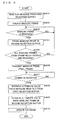
- FIG. 3 is a flowchart illustrating an example of a processing procedure performed when a control section of a relay device constructing the vehicle-mounted communication system according to Embodiment 1 receives a message.
- FIGS. 4A and 4B are explanatory views illustrating a format example of a mainline frame transmitted by a control section of a relay device constructing the vehicle-mounted communication system according to Embodiment 1.
- FIG. 5 is an explanatory view illustrating an example of the contents of a correspondence table stored in a storage section of a relay device constructing the vehicle-mounted communication system according to Embodiment 1.
- FIG. 6 is a flowchart illustrating an example of a processing procedure to be executed by a control section of a relay device serving as a specified relay device in Embodiment 1 to transmit and receive a mainline frame and update a database.
- FIG. 7 is a flowchart illustrating an example of a processing procedure to be executed by a control section of a relay device in Embodiment 1 to transmit and receive a mainline frame and update a database.
- FIG. 8 is a flowchart illustrating an example of a processing procedure to be executed by a control section of a relay device in Embodiment 1 to transmit and receive a mainline frame and update a database.
- FIG. 9 is an explanatory view schematically illustrating a process of updating databases in relay devices in Embodiment 1 by transmission and reception of mainline frames.
- FIG. 10 is a flowchart illustrating an example of a processing procedure to be executed by a control section of a relay device in Embodiment 2 to transmit and receive a mainline frame and update a database.
- FIG. 11 is a flowchart illustrating an example of a processing procedure to be executed by a control section of a relay device in Embodiment 2 to transmit and receive a mainline frame and update a database.
- FIG. 12 is a flowchart illustrating an example of a processing procedure to be executed by a control section of a relay device in Embodiment 2 to transmit and receive a mainline frame and update a database.
- FIG. 13 is a flowchart illustrating an example of a processing procedure to be executed by a control section of a relay device in Embodiment 2 to transmit and receive a mainline frame and update a database.
- FIG. 14 is a flowchart illustrating details of processing in response to COMMIT presence/absence information executed by a control section of a relay device in Embodiment 2.
- FIG. 15 a flowchart illustrating an example of a processing procedure to be executed by a control section of a relay device in Embodiment 2 to transmit and receive a mainline frame and update a database.
- FIG. 16 a flowchart illustrating an example of a processing procedure to be executed by a control section of a relay device in Embodiment 2 to transmit and receive a mainline frame and update a database.
- FIG. 17 is an explanatory view schematically illustrating a process of updating databases in relay devices in Embodiment 2 by transmission and reception of mainline frames.
- FIG. 18 is an explanatory view schematically illustrating a process of updating databases in relay devices in Embodiment 2 by transmission and reception of mainline frames.
- FIG. 1 is a configuration diagram illustrating the configuration of a vehicle-mounted communication system according to Embodiment 1.
- the vehicle-mounted communication system is a communication device that transmits and receives data, and includes: ECUs 1 a , . . . , 1 b , . . . , 1 c , . . . , 1 d , . . . , 1 e , . . . , 1 f , . . . , 1 g , . . . and 1 h , . . .
- relay devices 3 a , 3 b , 3 c and 3 d that are connected to the communication lines 2 a , 2 b , 2 c , 2 d , 2 e , 2 f , 2 g and 2 h while relaying transmission and reception of data among ECUs 1 a , . . . , 1 b , . . . , 1 c , . . . , 1 d , . . . , 1 e , . . . , 1 f , . . . , 1 g , . . . and 1 h , . . . ; and communication lines 4 a , 4 b and 4 c that connect the relay devices 3 a , 3 b , 3 c and 3 d with one another.
- the vehicle-mounted communication system in Embodiment 1 constructs a mainline-type vehicle-mounted network that connects the plurality of groups of ECUs 1 a , . . . , 1 b , . . . , 1 c , . . . , 1 d , . . . , 1 e , . . . , 1 f , . . . , 1 g , . . . and 1 h , . . . via the relay devices 3 a , 3 b , 3 c and 3 d connected through the communication lines 4 a , 4 b and 4 c which serve as main lines.
- the communication lines 2 a , 2 b , 2 c , 2 d , 2 e , 2 f , 2 g and 2 h will be referred to as branch lines 2 a , 2 b , 2 c , 2 d , 2 e , 2 f , 2 g and 2 h
- the communication lines 4 a , 4 b and 4 c will be referred to as main lines 4 a , 4 b and 4 c.
- the ECUs 1 a , 1 a , . . . ; the ECUs 1 b , 1 b , . . . ; the ECUs 1 c , 1 c , . . . ; and ECUs 1 d , 1 d , . . . are connected to the branch lines 2 a , 2 b , 2 c and 2 d , respectively.
- ECUs 1 h , 1 h , . . . are connected to the branch lines 2 e , 2 f , 2 g and 2 h , respectively.
- FIG. 1 a bus structure as illustrated in FIG. 1 .
- CAN Controller Area Network
- connection configuration of the branch lines 2 a , 2 b , 2 c , 2 d , 2 e , 2 f , 2 g and 2 h is, however, not limited to the above and may be any other form such as star, daisy chain or the like.
- daisy chain connection is employed for the connection configuration between the relay devices 3 a , 3 b , 3 c and 3 d via the main lines 4 a , 4 b and 4 c .
- the relay devices 3 a and 3 b are connected via the main line 4 a .
- the relay devices 3 b and 3 c are connected via the main line 4 b .
- the relay devices 3 c and 3 d are connected via the main line 4 c .
- the relay devices 3 a , 3 b , 3 c and 3 d are provided with storage areas used as databases 31 a , 31 b , 31 c and 31 d (data storage means), respectively.
- the relay device 3 a basically stores the data transmitted from the ECUs 1 a , 1 a , . . . and 1 b , 1 b , . . . , which are connected via the branch lines 2 a and 2 b , in the database 31 a .
- the relay device 3 a transmits the data read out from the database 31 a to the ECUs 1 a , 1 a , . . . and 1 b , 1 b , . . . .
- the relay device 3 a transmits the data received from the ECUs 1 a , 1 a , . . . and 1 b , 1 b , . . .
- the other relay devices 3 b , 3 c and 3 d store the data received from the relay devices 3 a , 3 b , 3 c and 3 d in the databases 31 b , 31 c and 31 d , respectively.
- the databases 31 a , 31 b , 31 c and 31 d are synchronized to have the same contents, allowing the ECUs 1 a , . . . , 1 b , . . . , 1 c , . . .
- FIG. 2 is a block diagram illustrating the internal structure of the ECU 1 c and the relay device 3 b constructing the vehicle-mounted communication system according to Embodiment 1.
- the ECU 1 c includes a control section 10 controlling the operation of components, a storage section 11 storing data required for control and a communication control section 12 controlling communication with the branch line 2 c . Since the other ECUs 1 a , 1 b , 1 d , 1 e , 1 f , 1 g and 1 h have similar internal structures as the ECU 1 c , detailed description thereof will not be repeated here.
- the control section 10 in the ECU 1 c is supplied with electric power from an electric-power supply device such as a battery, an alternator or the like of a vehicle, not illustrated, to control the operation of components.
- an electric-power supply device such as a battery, an alternator or the like of a vehicle, not illustrated
- the storage section 11 uses a volatile memory.
- the control section 10 temporarily stores, in the storage section 11 , various types of information generated during the process, a measurement value indicated by a signal input from a sensor as will be described later, or data received from the relay device 3 b.
- the communication control section 12 has the function of a network controller to implement communication with the communication line 2 c .
- the control section 10 in the ECU 1 c transmits and receives data via the communication control section 12 .
- ECUs 1 a , . . . , 1 b , . . . , 1 c , . . . , 1 d , . . . , 1 e , . . . , 1 f , . . . , 1 g , . . . and 1 h , . . . are devices capable of transmission of data including numerical information of various physical amounts such as a measurement value, a calculation value and a control value, or capable of control by a microcomputer such as an engine, a brake or the like.
- the ECU 1 c functions as ABS (Antilock Brake System) and is connected to a sensor (not illustrated) that detects the rotating speed of wheels (wheel speed).
- the ECU 1 c controls the brake based on the wheel speed detected via the sensor at the time of braking the vehicle, while transmitting the measurement value of the wheel speed as data to the relay device 3 b via the communication line 2 c.
- the data transmitted from each of the ECUs 1 a , . . . , 1 b , . . . , 1 c , . . . , 1 d , . . . , 1 e , . . . , 1 f , . . . , 1 g , . . . and 1 h , . . . is constructed by a pair of an attribute value ID (Identification Data) identifying an attribute of data such as the wheel speed, temperature, angle or the like and its specific numerical information (attribute value).
- ID Identity Data
- the data indicating the wheel speed is formed by a pair of an attribute value ID “10,” which is assigned to the wheel speed, and an attribute value “3000 (rpm: revolutions per minute).”
- the numerical information also includes a control value used for switching such as on, off, high, medium, low or the like, which is indicated by numerical information (on: 1, off: 1, high: 1, medium: 0, low: ⁇ 1).
- transmission and reception of data between the ECUs 1 a , . . . , 1 b , . . . , 1 c , . . . , 1 d , . . . , 1 e , . . . , 1 f , . . . , 1 g , . . . , 1 h , . . . and the relay devices 3 a , 3 b , 3 c , 3 d are executed by transmission and reception of a “message” in which a plurality of data are put together.
- each of the ECUs 1 a , 1 b , 1 c , 1 d , 1 e , 1 f , 1 g , 1 h , . . . transmits a group of data obtained by its own operation as a message.
- the communication lines (branch lines) 2 c , 2 d communication lines based on the CAN protocol are used, and the communication control section 12 in each of the ECU 1 c , 1 c , . . . , 1 d , 1 d , . . . transmits and receives a message via each of the branch lines 2 c and 2 d based on the CAN protocol.
- the message includes a message ID provided for each combination of a plurality of data, i.e. “CAN ID,” and each of the ECU 1 c , 1 c , . . . , 1 d , 1 d , . . . transmits a group of attribute values at once in accordance with each combination.
- the branch lines 2 c and 2 d are not limited thereto, and may transmit and receive a message based on a protocol such as LIN (Local Interconnect Network), FlexRay (registered trademark) or the like.
- the other branch lines 2 a , 2 b , 2 e , 2 f , 2 g and 2 h are similar to the communication lines 2 c and 2 d .
- each of the branch lines 2 a , 2 b , 2 c , 2 d , 2 e , 2 f , 2 g and 2 h may also be constructed by a communication line with a different protocol in accordance with the type of data transmitted to and received from each of the ECUs 1 a , . . .
- the relay device 3 b includes a control section 30 b (update means, judgment means) controlling the operation of components, a branch line communication section 32 b (first communication means) connected to the branch lines 2 c and 2 d , a temporary storage area 33 b using a volatile memory such as DRAM (Dynamic Random Access Memory) or SRAM (Static Random Access Memory), and a storage section 34 b using a non-volatile memory such as EPROM (Erasable Programmable Read Only Memory), EEPROM (Electrically EPROM) or a flash memory.
- a control section 30 b update means, judgment means controlling the operation of components
- a branch line communication section 32 b first communication means connected to the branch lines 2 c and 2 d
- a temporary storage area 33 b using a volatile memory such as DRAM (Dynamic Random Access Memory) or SRAM (Static Random Access Memory)
- a storage section 34 b using a non-volatile memory such as EPROM (Eras
- the relay device 3 b further includes a first mainline communication section 35 b (second communication means) connected to a main line 4 a and a second mainline communication section 36 b (second communication means) connected to a main line 4 b . Since each of the relay devices 3 a , 3 e and 3 d has an internal structure similar to that of the relay device 3 b , detailed description will not be repeated here.
- the control section 30 b uses MPU (Micro Processing Unit) and is supplied with electrical power from an electrical power supply device such as an alternator or a battery of a vehicle, not illustrated, to control the operation of components.
- MPU Micro Processing Unit
- the branch line communication section 32 b implements transmission and reception of data with the ECUs 1 c , 1 c , . . . , 1 d , 1 d , . . . connected via the branch lines 2 c and 2 d . Transmission and reception of data between the relay device 3 b and the ECUs 1 c , 1 c , . . . , 1 d , 1 d , . . . are implemented by transmission and reception of a message as described above.
- the branch line communication section 32 b is so configured to have a plurality of ports, while messages can be transmitted to and received from the ports simultaneously.
- the branch line communication section 32 b included in the relay device 3 b in Embodiment 1 has eight ports, and is capable of simultaneous transmission and reception of messages to/from the eight ports.
- the temporary storage area 33 b is provided with a storage area for the database 31 b in which the control section 30 b stores data.
- the database 31 b may alternatively be provided in a region in a storage device located outside the relay device 3 b , and be connected to the relay device 3 b to enable reading and writing.
- storage areas for the first reception buffer 37 b (first buffer means) and the second reception buffer 38 b (second buffer means) that temporality store the received data (message) are provided in the temporary storage area 33 b.
- a correspondence table 39 b which is referred to when the control section 30 b communicates with another relay device through the first mainline communication section 35 b is stored in advance.
- the correspondence table 39 b will be described later in detail.
- the correspondence tables 39 a , 39 b , 39 c and 39 d stored in the relay devices 3 a , 3 b , 3 c and 3 d , respectively, have the same contents.
- the first mainline communication section 35 b implements communication with the relay device 3 a connected via the main line 4 a .
- the second mainline communication section 36 b implements communication with the relay device 3 c connected via the main line 4 b .
- the control section 30 b is capable of simultaneous communication with the relay device 3 a through the first mainline communication section 35 b and with the relay device 3 c through the second mainline communication section 36 b.
- the control section 30 b periodically performs communication with other relay devices 3 a , 3 c through the first mainline communication section 35 b and the second mainline communication section 36 b every certain period of time, e.g. one millisecond. In the description below, such a period is referred to as a synchronizing period.
- a synchronizing period In the other relay devices 3 a , 3 c and 3 d , communication is periodically performed every certain period of time, which is accurately synchronized in time. For synchronizing the periods, either an existing or a new method may be employed.
- the relay device 3 a may have the function of receiving electric waves from a GPS (Global Positioning System) satellite to obtain time information while synchronizing a timer included in the relay device 3 a with a timer included in each of the other relay devices 3 b , 3 c , 3 d based on the obtained time information.
- a GPS Global Positioning System
- the relay device 3 a is also provided with the first mainline communication section 35 a and the second mainline communication section 36 a , and is capable of simultaneous communication. In Embodiment 1, however, the relay device 3 a is connected to the relay device 3 b via the main line 4 a through the second mainline communication section 36 a . In Embodiment 1, since the relay device 3 a is not connected to any relay device other than the relay device 3 b , the first mainline communication section 35 a is not used. Likewise, the relay device 3 d is also provided with the first mainline communication section 35 d and the second mainline communication section 36 d .
- the relay device 3 d is connected to the relay device 3 c via the main line 4 c through the mainline communication section 35 d , not using the second mainline communication section 36 d .
- the second mainline communication section 36 d may be used to connect the devices in a daisy chain form, while the relay device 3 d implements communication with the relay device 3 c through the first mainline communication section 35 d and communication with another relay device through the second mainline communication section 36 d.
- the communication processing between the ECUs 1 a , . . . , 1 b , . . . , 1 c , . . . , 1 d , . . . , 1 e , . . . , 1 f , . . . , 1 g , . . . , 1 h , . . . and the relay devices 3 a , 3 b , 3 c , 3 d in the vehicle-mounted communication system constructed as described above will be described.
- FIG. 3 is a flowchart illustrating an example of the processing procedure in the case where the control section 30 a in the relay device 3 a constructing the vehicle-mounted communication system in Embodiment 1 receives a message. Since the processing procedures performed by the control sections 30 b , 30 c and 30 d in the other relay devices 3 b , 3 c and 3 d are similar to that performed by the control section 30 a in the relay device 3 a , detailed description thereof will not be repeated here.
- the control section 30 a judges whether or not the branch line communication section 32 a has received a message transmitted from the ECUs 1 a , 1 a , . . . , 1 b , 1 b , . . . connected via the branch lines 2 a and 2 b (step S 11 ).
- the control section 30 a judges that the message has not been received (NO at step S 11 )
- the processing goes back to the step S 11 .
- control section 30 a judges that the message has been received (YES at step S 11 )
- it once stores the received message in the first reception buffer 37 a (step S 12 ) and terminates the processing in the case where the message has been received.
- the control section 30 a continues performing the processing procedure shown in the flowchart of FIG. 3 . That is, each time a message is received from the ECU 1 a , 1 a , . . . , 1 b , 1 b , . . . , the control section 30 a stores the message.
- a group of attribute values included in the message stored in the first reception buffer 37 a are stored in the database 31 a for each attribute value ID at a timing described later.
- an attribute value ID and an attribute value are stored in the database 31 a in the form of a pair.
- the control section 30 a creates a message from the attribute values of data stored in the database 31 a and appropriately transmits it to the ECU 1 a , 1 a , . . . , 1 b , 1 b that require the message through the branch line communication section 32 a .
- the timing of transmission may be, for example, scheduled for each of the ECUs 1 a , 1 a , . . . , 1 b , 1 b , . . . to which the message is transmitted.
- the control section 30 a generates and transmits a message with reference to a schedule stored in the storage section 34 a .
- control section 30 a may also monitor an attribute value stored in the database 31 a and, when the attribute value is changed by updating the database 31 a , transmit the message to ECUs 1 a , 1 a , . . . , 1 b , 1 b , . . . that require the message including the attribute value.
- the control section 30 a When the data stored in the database 31 a is exchanged with the other relay devices 3 b , 3 c and 3 d , the control section 30 a basically performs the processing as described below.
- the control section 30 a does not read out the data including a pair of an attribute value and an attribute value ID identifying the attribute value from the database 31 a and transmitting the data, but performs transmission and reception using the message once stored in the first reception buffer 37 b . More specifically, the control section 30 a transmits a frame in which messages are put together. Such a frame will be referred to as a mainline frame in the description below.
- the control section 30 a in the relay device 3 a then receives the mainline frame transmitted from the other relay devices 3 b , 3 c and 3 d through the second mainline communication section 36 a .
- the control section 30 a stores the received mainline frame in the second reception buffer 38 a .
- the groups of attribute values included in messages of the mainline frame stored in the second reception buffer 38 a are then stored in the database 31 a at a timing described later.
- control section 30 b in the relay device 3 b stores the mainline frame received through the first mainline communication section 35 b in the second reception buffer 38 b while transferring it through the second mainline communication section 36 b .
- control section 30 b in the relay device 3 b can perform transmission/reception through the first mainline communication section 35 b and transmission/reception through the second mainline communication section 36 b at the same time.
- the control section 30 b transmits the mainline frame created by the control section 30 b to the relay device 3 c through the second mainline communication section 36 b , while receiving the mainline frame transmitted from the relay device 3 a through the first mainline communication section 35 b .
- the control section 30 b gives priority to reception in the first mainline communication section 35 b and to transmission in the second mainline communication section 36 b .
- the control section 30 c in the relay device 3 c operates similarly to the control section 30 b in the relay device 3 b.
- control section 30 d in the relay device 3 d When the control section 30 d in the relay device 3 d receives a mainline frame from the relay device 3 c , it stores the frame in the second reception buffer 38 d .
- the control section 30 d in the relay device 3 d gives priority to reception over transmission in the first mainline communication section 35 d . That is, the control section 30 d does not transmit the mainline frame created by the control section 30 d until the first mainline communication section 35 d receives all of the mainline frame created and transmitted by the relay device 3 c and the mainline frame received and transferred by the relay device 3 c.
- the message transmitted and received in accordance with CAN is constructed by one or more combinations of attribute values, each combination being provided with a CAN ID. Therefore, use of a message may cut out transmission of an attribute value ID for each attribute value.
- another structure may also be employed in that a data frame including attribute values which are more efficiently put together compared to the message transmitted from the ECUs 1 a , 1 a , . . . , 1 b , 1 b , . . . is newly defined while a data frame ID is defined in association with the number of attribute values included in the data frame and an attribute value ID corresponding to each attribute value.
- FIGS. 4A and 4B are explanatory views illustrating a format example of a mainline frame transmitted by the control sections 30 a , 30 b , 30 c and 30 d of the relay devices 3 a , 3 b , 3 c and 3 d constructing the vehicle-mounted communication system according to Embodiment 1.
- FIG. 4A shows a format example of a mainline frame transmitted by the control sections 30 a , 30 b , 30 c , 30 d in the relay devices 3 a , 3 b , 3 c , 3 d in Embodiment 1
- FIG. 4B shows, for comparison, a format example in the case where a plurality of data including attribute value IDs and attribute values are transmitted.
- a header is attached at the beginning, while a trailer indicating termination of the mainline frame is attached at the end.
- m messages that have been received from the ECU 1 a , 1 a , . . . , 1 b , 1 b , . . . by the relay device 3 a and stored in the first reception buffer 37 a are included.
- a message ID (CAN ID) which is pre-determined in accordance with the number of attribute values and the combination of the attribute value IDs and assigned to each message; and the total size of the immediately-following group of attribute values (information length).
- the maximum size of the sum of the group of attribute values included in the message corresponds to 8 bytes.
- the field itself which indicates the size of the field of the group of attribute values (information length) in byte units corresponds to 4 bits since the maximum number is eight. Because the CAN ID is indicated by 11 bits, the size of one message corresponds to 10 bytes when it is round out in byte units.
- FIG. 4B shows, for comparison with FIG. 4A , an example where a plurality of data including attribute value IDs and attribute values are transmitted.
- a header is attached at the beginning while a trailer indicating termination of transmission is attached at the end.
- k attribute values are included in the message received from the ECU 1 a , 1 a , . . . , 1 b , 1 b , . . . by the relay device 3 a and stored in the first reception buffer 37 a
- k pairs of attribute value IDs and attribute values are included between the header and trailer.
- an attribute value ID is indicated by 2 bytes.
- FIG. 5 is an explanatory view illustrating an example of the contents of the correspondence table 39 a stored in the storage section 34 a of the relay device 3 a constructing the vehicle-mounted communication system according to Embodiment 1.
- n in FIG. 5 indicates an arbitrary natural number.
- the number of attribute values included is stored in association with each message ID while an attribute value ID, a position (order) in a message and an information length (in bit units) are stored for each of the included attribute values.
- the content example of FIG. 5 shows that the message with the message ID “1” includes “2” attribute values.
- the first attribute value included in the message with the message ID “1” has an attribute value ID of “1” and is included “1st” in the order with the information length of “1” bit
- the second attribute value has an attribute value ID of “2” and is included “2nd” in the order with the information length of “1” bit.
- FIG. 5 shows that the message with the message ID “2” includes “4” attribute values. It shows that the first attribute value included in the message with the message ID “2” has an attribute value ID of “20” and is included “2nd” in the order with the information length of “1” bit, and that the second attribute value has an attribute value ID of “50” and is included “4th” in the order with the information length of “8” bits. It also shows that the message with the message ID “3” includes “n” attribute values. The first attribute value included in the message with the message ID “3” has an attribute value ID of “8” and is included “4th” in the order with the information length of “3” bits.
- the second attribute value has an attribute value ID of “5” and is included “nth” in the order with the information length of “4” bits. It can also be seen that the message with the message ID “4” includes “64” attribute values.
- the first attribute value included in the message with the message ID “4” has an attribute value ID of “1” and is included “1st” in the order with the information length of “1” bit.
- the second attribute value has an attribute value ID of “2” and is included “2nd” in the order with the information length of “1” bit.
- control sections 30 a , 30 b , 30 c and 30 d in the relay devices 3 a , 3 b , 3 c and 3 d receive mainline frames with the format shown in FIG. 4A , they store the received mainline frames in the second reception buffers 38 a , 38 b , 38 c and 38 d .
- the relay devices 3 b and 3 c receive mainline frames from either one of the first mainline communication sections 35 b , 35 c or the second mainline communication sections 36 b , 36 c , they transfer the frames to the other communication sections.
- control sections 30 a , 30 b , 30 c and 30 d retrieve attribute values from mainline frames stored in the second reception buffers 38 a , 38 b , 38 c and 38 d with reference to the correspondence tables 39 a , 39 b , 39 c and 39 d , respectively, based on message IDs.
- the control sections 30 a , 30 b , 30 c and 30 d in the relay devices 3 a , 3 b , 3 c and 3 d can recognize which data's attribute values are included in the messages and retrieve them even when the relay devices 3 a , 3 b , 3 c and 3 d transmit and receive data using messages including only attribute value groups but not including attribute value IDs and using mainline frames in which such messages are put together.
- control sections 30 a , 30 b , 30 c and 30 d may refer to the correspondence tables 39 a , 39 b , 39 c and 39 d when they receive mainline frames to retrieve attribute values in advance based on data frame IDs and store them in the second reception buffers 38 a , 38 b , 38 c and 38 d.
- the messages received from the ECUs 1 a , . . . , 1 b , . . . , 1 c , . . . , 1 d , . . . , 1 e , . . . , 1 f , . . . , 1 g , . . . and 1 h , . . . are stored in the first reception buffers 37 a , 37 b , 37 c and 37 d .
- mainline frames exchanged among the relay devices 3 a , 3 b , 3 c and 3 d are stored in the second reception buffers 38 a , 38 b , 38 c and 38 d.
- the relay device 3 a located at one end (leading end) of the daisy chain form functions as a specified relay device, issuing COMMIT (notice of determination) indicating that the data to be stored in the databases 31 a , 31 b , 31 c and 31 d can be determined.
- the relay device 3 a transmits COMMIT through the second mainline communication section 36 a to the relay device 3 b .
- the relay device 3 b which received COMMIT from the relay device 3 a transfers COMMIT to the neighboring relay device 3 c .
- the relay device 3 c further transfers the received COMMIT to the relay device 3 d .
- the relay devices 3 a , 3 b , 3 c and 3 d When issuing or receiving COMMIT, the relay devices 3 a , 3 b , 3 c and 3 d reads out attribute value groups from the messages stored in the first reception buffers 37 a , 37 b , 37 c , 37 d and the second reception buffers 38 a , 38 b , 38 c , 38 d , to update the databases 31 a , 31 b , 31 c and 31 d , respectively.
- FIG. 6 is a flowchart illustrating an example of a processing procedure to be executed by the control section 30 a of the relay device 3 a serving as a specified relay device in Embodiment 1 to transmit and receive a mainline frame and update the database 31 a.
- the control section 30 a refers to the correspondence table 39 a in the storage section 34 a to read out a message from the first reception buffer 37 a which received the message from the ECUs 1 a , 1 a , . . . , 1 b , 1 b , . . . and temporarily stores it therein (step S 201 ), create a mainline frame (step S 202 ), and transmit the created mainline frame through the second mainline communication section 36 a to the relay device 3 b (step S 203 ).
- the control section 30 a judges whether or not a mainline frame transmitted from other relay device 3 b , 3 c or 3 d has been received by the second mainline communication section 36 a (step S 204 ).
- the control section 30 a judges that no main line frame has been received (NO at S 204 )
- it returns the processing back to the step S 204 .
- the control section 30 a judges that a mainline frame has been received (YES at S 204 )
- it stores the received mainline frame in the second reception buffer 38 a (step S 205 ).
- the control section 30 a judges whether or not the final frame has been received by checking if the received mainline frame is the one transmitted from the relay device 3 d (step S 206 ).
- the control section 30 a can identify the sender. It can also be identified by a message ID included in the mainline frame.
- the relay device 3 d does not transmit the mainline frame created by the relay device 3 d until it receives all of the mainline frames transmitted from the relay devices 3 a , 3 b and 3 c .
- the relay device 3 d transmitting the mainline frame means that all the other mainline frames including the mainline frame from the relay device 3 a have reached the relay device 3 d . That is, the mainline frame transmitted from the relay device 3 d located the farthest from the relay device 3 a which serves as a specified relay device functions as an acknowledge (ACK) for the relay device 3 a .
- the acknowledge is then transferred from the relay device 3 d and received by the relay device 3 a in series, so that the relay device 3 a can confirm that all mainline frames including the final frame have been received also at the relay devices 3 b and 3 c.
- control section 30 a judges that the received mainline frame is not the one transmitted from the relay device 3 d and that the frame is not the final frame (NO at S 206 ), it returns the processing back to the step S 204 .
- the control section 30 a judges that the received mainline frame is the one transmitted from the relay device 3 d , which is the final frame (YES at S 206 ), meaning that transmission and reception of a mainline frame are successful at all of the relay devices 3 a , 3 b , 3 c and 3 d
- the control section 30 a issues COMMIT so as to determine and update the data to be stored in the databases 31 b , 31 c , 31 d at the relay devices 3 b , 3 c , 3 d and transmits it to the relay device 3 b (step S 207 ).
- the control section 30 a then retrieves attribute values from the message read out from the first reception buffer 37 a at the step S 201 (step S 208 ) while it also retrieves attribute values from the message included in the mainline frame stored in the second reception buffer 38 a (step S 209 ).
- the control section 30 a stores the attribute values retrieved at the steps S 208 and S 209 in the database 31 a to update the database 31 a (step S 210 ), and terminates the processing.
- FIG. 7 is a flowchart illustrating an example of a processing procedure to be executed by the control section 30 b of the relay device 3 b in Embodiment 1 to transmit and receive a mainline frame and update the database 31 b . Since the processing procedure performed by the control section 30 c in the relay device 3 c is similar to the processing procedure by the control section 30 b in the relay device 3 b , detailed description thereof will not be repeated here.
- the control section 30 b refers to the correspondence table 39 b in the storage section 34 b and reads out a message from the first reception buffer 37 b which has received messages from ECUs 1 c , 1 c , . . . , 1 d , 1 d , . . . and has temporarily stored them (step S 301 ).
- the control section 30 b creates a mainline frame using the read-out message (step S 302 ).
- the control section 30 b judges whether or not either of the first mainline communication section 35 b or the second mainline communication section 36 b started receiving a mainline frame from other relay devices 3 a or 3 c , or whether or not either of the first mainline communication section 35 b or the second mainline communication section 36 b can transmit a mainline frame when there is a mainline frame to be transmitted (step S 303 ).
- the control section 30 b returns the processing back to the step S 303 .
- control section 30 b judges that either of the first mainline communication section 35 b or the second mainline communication section 36 b started receiving a mainline frame from the other relay devices 3 a or 3 c , or that either of the first mainline communication section 35 b or the second mainline communication section 36 b can transmit a mainline frame when there is a mainline frame to be transmitted (YES at S 303 ), it judges whether or not the mainline frame is being received (step S 304 ). When the control section 30 b judges that the mainline frame is being received (YES at S 304 ), it temporarily stores the received mainline frame in the second reception buffer (step S 305 ).
- control section 30 b judges whether or not either of the first mainline communication section 35 b or the second mainline communication section 36 b can transmit the mainline frame to be transmitted (step S 306 ).
- control section 30 b judges that the transmission is impossible (NO at S 306 )
- it returns the processing back to the step S 303 .
- the control section 30 b transmits the mainline frame created by the control section 30 b or the mainline frame which is received from the other relay device 3 a or 3 c and temporarily stored to be transmitted to another device (step S 307 ).
- the processing is forwarded to the step S 306 when it is judged that no mainline frame is received at the step S 304 .
- the control section 30 b can, however, perform the transmission or reception by the first mainline communication section 35 b and the transmission or reception by the second mainline communication section 36 b at the same time.
- the control section 30 b can receive a mainline frame by the first mainline communication section 35 b while transmitting a mainline frame by the second mainline communication section 36 b .
- the control section 30 b receives and temporarily stores the mainline frame (S 305 ) while proceeding to the step S 306 and transmitting a mainline frame when either of the first mainline communication section 35 b or the second mainline communication section 36 b is available and when there is a mainline frame to be transmitted (S 307 ).
- control section 30 b judges whether or not the mainline frame, i.e. the final frame, transmitted from the relay device 3 d which received all the mainline frames as described later has been received (step S 308 ). When it is judged that the final frame has not been received (NO at S 308 ), the control section 30 b returns the processing back to the step S 303 .
- Reception of the final frame indicates that the control section 30 b has received mainline frames from all the relay devices 3 b , 3 c and 3 d other than itself.
- the control section 30 b judges that the final frame has been received (YES at S 308 )
- the control section 30 b judges that COMMIT has not been received (NO at S 309 )
- control section 30 b When the control section 30 b judges that COMMIT has been received (YES at S 309 ), it retrieves attribute values from the message read out from the first reception buffer 37 b at the step S 301 (step S 310 ). Moreover, the control section 30 b retrieves attribute values from the message in the mainline frame stored in the second reception buffer 38 b (step S 311 ). The control section 30 b updates the database 31 b by storing the attribute values retrieved at the steps S 310 and S 311 in the database 31 b (step S 312 ) and terminates the processing.
- FIG. 8 is a flowchart illustrating an example of a processing procedure to be executed by the control section 30 d of the relay device 3 d in Embodiment 1 to transmit and receive a mainline frame and update the database 31 d .
- the relay device 3 d is located at an end of the relay devices 3 a , 3 b , 3 c and 3 d connected in a daisy-chain form, opposite from the specified relay device 3 a which is located at one end thereof.
- the relay device 3 d thus performs processing partly different from those performed by the relay devices 3 b and 3 c that are located in between.
- the control section 30 d refers to the correspondence table 39 d of the storage section 34 d to read out a message from the first reception buffer 37 d which received the messages from the ECUs 1 g , 1 g , . . . , 1 h , 1 h , . . . and temporarily stores them (step S 401 ).
- the control section 30 d creates a mainline frame from the read-out message (step S 402 ).
- the control section 30 d judges whether or not the first mainline communication section 35 d has received a mainline frame transmitted from another relay device 3 a , 3 b or 3 c (step S 403 ). When the control section 30 d judges that no mainline frame has been received (NO at S 403 ), it returns the processing back to the step S 403 . When the control section 30 d judges that a mainline frame has been received (YES at S 403 ), it stores the received mainline frame in the second reception buffer 38 d (step S 404 ).
- control section 30 d judges whether or not all the mainline frames transmitted from the other relay devices 3 a , 3 b and 3 c have been received (step S 405 ). When it is judged that not all of them have been received (NO at S 405 ), the control section 30 d returns the processing back to the step S 403 . When it is judged that all of them have been received (YES at S 405 ), the control section 30 d transmits the mainline frame created by the control section 30 d at the step S 402 as the final frame through the first mainline communication section 35 d (step S 406 ). The final frame serves as an acknowledge for the relay device 3 a as described above.
- the control section 30 d judges whether or not COMMIT issued from the relay device 3 a has been received (step S 407 ). When the control section 30 d judges that no COMMIT has been received (NO at S 407 ), it returns the processing back to the step S 407 and waits until it judges that COMMIT is received.
- the control section 30 d retrieves attribute values from the message read out from the first reception buffer 37 d at the step S 401 (step S 408 ). Moreover, the control section 30 d retrieves attribute values from the message in the mainline frame stored in the second reception buffer 38 d (step S 409 ). The control section 30 d updates the database 31 d by storing the attribute values retrieved at the steps S 408 and S 409 in the database 31 d (step S 410 ) and terminates the processing.
- FIG. 9 is an explanatory view schematically illustrating a process of updating the databases 31 a , 31 b , 31 c and 31 d in the relay devices 3 a , 3 b , 3 c and 3 d in Embodiment 1 by transmission and reception of mainline frames.
- the explanatory view of FIG. 9 shows the daisy-chain connection among the relay devices 3 a , 3 b , 3 c and 3 d in a block diagram. It also shows, in a block diagram, the configuration of the databases 31 a , 31 b , 31 c and 31 d , the first reception buffers 37 a , 37 b , 37 c , 37 d and the second reception buffers 38 a , 38 b , 38 c , 38 d in the relay devices 3 a , 3 b , 3 c and 3 d . Moreover, the explanatory view of FIG.
- FIG. 9 shows in chronological order that the control sections 30 a , 30 b , 30 c , 30 d in the relay devices 3 a , 3 b , 3 c , 3 d execute the processing procedures illustrated in the flowcharts of FIGS. 6 to 8 to transmit and receive mainline frames.
- the unnumbered blocks in FIG. 9 indicate the second reception buffers 38 a , 38 b , 38 c and 38 d.
- attribute value groups A, B, C and D to be included in the mainline frames are read out from the messages stored in the first reception buffers 37 a , 37 b , 37 c and 37 d , respectively.
- they are temporarily stored in the second reception buffers 38 a , 38 b , 38 c and 38 d together with the attribute value groups included in the mainline frames received from other relay devices. It is, however, not limited thereto and the read-out attribute value groups may also be stored in other storage areas in the temporary storage areas 33 a , 33 b , 33 c and 33 d.
- the relay device 3 a transmits the mainline frame including the attribute value group A, read out from the first reception buffer 37 a and created, to the relay device 3 b .
- priority is given to reception in the first mainline communication section 35 a , 35 b , 35 c and 35 d and to transmission in the second mainline communication section 36 a , 36 b , 36 c and 36 d in each of the relay devices 3 a , 3 b , 3 c and 3 d .
- the relay device 3 b receives the mainline frame transmitted from the relay device 3 a while it transmits the mainline frame including the attribute value group B to the relay device 3 c .
- the relay device 3 b retrieves the attribute value group A from the mainline frame and stores it in the second reception buffer 38 b .
- the relay device 3 c receives the mainline frame transmitted from the relay device 3 a while it transmits the mainline frame including the attribute value group C to the relay device 3 d.
- the relay device 3 b transmits the mainline frame including the attribute value group A received from the relay device 3 a to the relay device 3 c , while it transmits the mainline frame including the attribute value group B to the relay device 3 a , since the first mainline communication section 35 b is available.
- the relay device 3 c transfers the mainline frame including the attribute value group B received from the relay device 3 b to the relay device 3 d , since the second mainline communication section 36 c becomes available. Accordingly, the attribute value groups A, B, C are stored in the second reception buffer 38 c in the relay device 3 c.
- the relay device 3 c transmits the mainline frame including the attribute value group C to the relay device 3 b since the first mainline communication section 35 c becomes available, while it transfers the mainline frame including the attribute value group A received from the relay device 3 b to the relay device 3 d . Accordingly, all the attribute value groups A, B, C and D are stored in the second reception buffer 38 d in the relay device 3 d.
- the relay device 3 d Since the relay device 3 d has received all the mainline frames including the attribute value groups A, B and C, it transmits the mainline frame including the attribute value group D to the relay device 3 c as the final frame. At the same time, the relay device 3 b transfers the mainline frame including the attribute value group C received at a previous timing to the relay device 3 a . Accordingly, all the attribute value groups A, B, C and D are stored in the second reception buffer 38 c of the relay device 3 c.
- the final frame is transferred from the relay device 3 c to the relay device 3 b , and further from the relay device 3 b to the relay device 3 a . Accordingly, all the attribute value groups A, B, C and D are stored also in the second reception buffers 38 a and 38 b of the relay devices 3 a and 3 b .
- the relay device 3 a confirms that all the relay devices 3 a , 3 b , 3 c and 3 d have received all mainline frames, and issues COMMIT.
- the COMMIT issued from the relay device 3 a is transmitted from the relay device 3 a to the relay device 3 b , from the relay device 3 b to the relay device 3 c , and from the relay device 3 c to the relay device 3 d .
- the relay devices 3 a , 3 b , 3 c and 3 d retrieve attribute value groups from all mainline frames that are received and stored, to renew the databases 31 a , 31 b , 31 c and 31 d , respectively.
- the relay device 3 a serving as a specified relay device thus issues COMMIT and transfers COMMIT in sequence among the relay devices 3 b , 3 c and 3 d , so that the contents of the databases 31 a , 31 b , 31 c and 31 d are synchronized to have the same contents at almost the same time. They are not synchronized with each other when an error occurs in communication via the main lines 4 a , 4 b and 4 c , i.e., when the final frame is not received at the relay device 3 a serving as a specified relay device, or when COMMIT cannot be received at the relay devices 3 b , 3 c and 3 , for example.
- the contents of the databases 31 a , 31 b , 31 c and 31 d will be different from each other.
- the wheel speeds received by the ECU 1 b and ECU 1 c connected to the different branch lines 2 b and 2 c will have different concrete numerical values of 3000 (rpm) and 2500 (rpm), respectively.
- data to be used needs to be identical in each of the ECUs 1 a , . . . , 1 b , . . . , 1 c , . . . , 1 d , . . . , 1 e , . . . , 1 f , . . . , 1 g , . . . and 1 h , . . . .
- the processing performed by the relay devices 3 a , 3 b , 3 c and 3 d in Embodiment 1 can avoid the situation where the databases 31 a , 31 b , 31 c and 31 d have different contents, ensuring the data to be identical.
- Embodiment 1 communication among the relay devices 3 a , 3 b , 3 c and 3 d via the mainlines 4 a , 4 b and 4 c is performed with a format of a mainline frame including a plurality of messages each having a plurality of attribute values, so that transmission and reception of an attribute value ID for each attribute value may be omitted, allowing reduction in communication amount.
- the effect of reduction in communication amount will be described below with concrete numerical values.
- the relay devices 3 a , 3 b , 3 c and 3 d repeats the processing procedures shown in the flowchart of FIGS. 6 to 8 every one millisecond to transmit and receive mainline frames as illustrated in the explanatory view of FIG. 9 .
- An example will be described below where eight ports of each of the branch line communication sections 32 a , 32 b , 32 c and 32 d of the relay devices 3 a , 3 b , 3 c and 3 d receive messages including 64 attribute values, each value being 1 bit, four times until the period of one millisecond arrives.
- the communication amount required in transmission of attribute values from the relay device 3 a to the relay device 3 b by means of the mainline frame as shown in FIG. 4A is calculated as represented by the formula 1 below.
- 64 attribute values, each value being 1 bit, i.e. 8 bytes, are included in one message.
- one mainline frame is transmitted including 32 messages.
- the communication amount among the relay devices 3 a , 3 b , 3 c and 3 d before the databases 31 a , 31 b , 31 c and 31 d synchronize with one another is calculated as represented by the formula 2 below.
- mainline frames are transmitted and received twelve times among the relay devices 3 a , 3 b , 3 c and 3 d .
- each mainline frame is transmitted and received for each of the attribute value groups A, B, C and D, while simultaneous transmission and reception of mainline frames are performed.
- the time required for synchronization of the databases 31 a , 31 b , 31 c and 31 d in the period of one millisecond corresponds to the time required for transmission and reception of 1920 bytes via the main lines 4 a , 4 b and 4 c .
- the time required for transmission and reception of information of 1920 bytes is approximately 154 microseconds. Transmission and reception of 1920 bytes can be sufficiently performed during the period of one millisecond.
- the communication amount in the case where the relay device 3 a transmits attribute values to the relay device 3 b with the format in which the pairs of attribute value IDs and attribute values are included for the number of attribute values as shown in FIG. 4B will be described.
- the communication amount required for transmission from the relay device 3 a to the relay device 3 b will be calculated below as represented by the formula 3.
- the communication amount among the relay devices 3 a , 3 b , 3 c and 3 d will be calculated as represented by the formula 4 below.
- the relay devices 3 b , 3 c and 3 d adds the attribute value groups stored in their reception buffers 37 b , 37 c and 37 d to the received mainline frames and transfer them.
- the relay device 3 d that receives mainline frames including attribute value groups A, B and C transmits mainline frames including all the attribute value groups A, B, C and D to the relay device 3 c .
- the mainline frame including all the attribute value groups A, B, C and D is thus transferred sequentially from the relay device 3 c to the relay device 3 b , and from the relay device 3 b to the relay device 3 a .
- information amount of 78336 bytes needs to be transmitted and received among the main lines 4 a , 4 b and 4 c during the period of every one millisecond.
- the communication speed for the main lines 4 a , 4 b and 4 c is 100 Mbps
- the time required for transmission/reception of the information amount of 78336 bytes is 6 milliseconds. The period of one millisecond for transmission and reception is not sufficient.
- a mainline frame with the format as shown in FIG. 4A is created for transmission and reception. This can reduce the communication amount among the relay devices 3 a , 3 b , 3 c and 3 d to as small as approximately one fortieth. Hence, the time required for synchronization of the databases 31 a , 31 b , 31 c and 31 b among the relay devices 3 a , 3 b , 3 c and 3 d can be shortened, enabling the synchronization to be completed at high speed.
- Embodiment 1 an example was described where transmission and reception of both mainline frames and COMMIT among the relay devices 3 a , 3 b , 3 c and 3 d were successfully performed as shown in the flowcharts of FIGS. 6 to 8 and the explanatory view of FIG. 9 .
- the process of recovering as soon as possible and maintaining databases to be identical is additionally performed.
- Embodiment 2 The configuration of a vehicle-mounted communication system in Embodiment 2 is similar to that in Embodiment 1, except for the details of the processing performed by the relay devices 3 a , 3 b , 3 c and 3 d . Therefore, the components are denoted by the same reference codes as those in Embodiment 1 and detailed description thereof will not be repeated here. Different parts of the processing will be described below in detail.
- the relay devices 3 a , 3 b , 3 c and 3 d in Embodiment 2 store age information, indicating the length of time passed from storage or reception, in addition to the data stored in the databases 31 a , 31 b , 31 c and 31 d , respectively. More specifically, each time a synchronizing period passes, the control section 30 a , 30 b , 30 c and 30 d of the relay devices 3 a , 3 b , 3 c and 3 d adds, one by one, an age consisting of a natural number attached to an attribute value, when the attribute value is not updated.
- the relay device 3 a in Embodiment 2 stores, in the temporary storage area 33 a , the information on whether or not it has issued COMMIT during the synchronizing period.
- Each of the relay devices 3 b and 3 c also stores, in each of the temporary storage areas 33 b and 33 c , the information on whether or not the final frame has been received and whether or not COMMIT has been received during the synchronizing period.
- the relay device 3 d also stores information on whether or not COMMIT has been received during the synchronizing period.
- the relay device 3 a then transmits, together with the mainline frame created when the synchronizing period is started, COMMIT presence/absence information (notification information) indicating whether or not COMMIT was issued the previous time.
- COMMIT presence/absence information notification information
- each of the relay devices 3 b , 3 c and 3 d performs a recovering process when needed depending on the contents of the received information.
- FIGS. 10 and 11 are flowcharts illustrating examples of the processing procedure to be executed by the control section 30 a of the relay device 3 a in Embodiment 2 to transmit and receive a mainline frame and update the database 31 a . Note that the processing in common with the processing procedure shown in the flowchart of FIG. 6 in Embodiment 1 will be denoted by the same step numbers and will not be described here in detail.
- the control section 30 a creates a mainline frame (S 202 ), and then judges whether or not COMMIT was issued (COMMIT presence/absence) during the preceding synchronizing period with reference to the information stored in the temporary storage area 33 a (step S 51 ).
- the control section 30 a judges that the COMMIT was issued the previous time (YES at S 51 ), meaning that the databases 31 b , 31 c and 31 d are also supposed to be updated in the relay devices 3 b , 3 c and 3 d , it transmits the mainline frame created at the step S 202 and information of COMMIT presence indicating that COMMIT have been issued (step S 52 ).
- control section 30 a judges that no COMMIT was issued because the final frame was not received the previous time (NO at S 51 ), it retransmits the mainline frame that was transmitted the previous time (step S 53 ). To the attribute value group included in the retransmitted mainline frame, an age added by one is attached as will be described later. The control section 30 a then transmits the mainline frame created at the step S 202 and information of COMMIT absence indicating that COMMIT has not been issued (step S 54 ).
- the control section 30 a judges whether or not the synchronizing period of one millisecond has passed since the start of the processing (step S 55 ). When the control section 30 a judges that the synchronizing period has not passed yet (NO at S 55 ), it judges whether or not a mainline frame transmitted from the other relay devices 3 b , 3 c and 3 d has been received (S 204 ). When it is judged that no mainline frames have been received (NO at S 204 ), the processing is returned to the step S 55 .
- control section 30 a judges that a mainline frame has been received from any one of the other relay devices 3 b , 3 c and 3 d (YES at S 204 ), it stores the mainline frame (S 205 ) and judges whether or not the received mainline frame is the final frame (S 206 ). When the control section 30 a judges that the frame is not the final frame (NO at S 206 ), it returns the processing back to the step S 55 .
- control section 30 a When the control section 30 a receives the final frame (YES at 5206 ) and issues COMMIT (S 207 ), it stores that COMMIT has been issued (COMMIT presence) (step S 56 ), retrieves attribute values from the first reception buffer 37 a and the second reception buffer 38 a (S 208 , S 209 ), updates the database 31 a (S 210 ) and terminates the processing in the synchronizing period.
- control section 30 a judges that the synchronizing period has passed without the final frame being received (YES at S 55 ), it stores that COMMIT has not been issued (COMMIT absence) (step S 57 ), adds one to the age attached to the attribute value group included in the message read from the first reception buffer 37 a and the attribute value group included in the message in the mainline frame of the second reception buffer (step S 58 ), and terminates the process in the synchronizing period without updating the database 31 a.
- FIGS. 12 and 13 are flowcharts illustrating examples of the processing procedure to be executed by the control section 30 b of the relay device 3 b in Embodiment 2 to transmit and receive a mainline frame and update the database 31 b . Since the processing procedure performed by the control section 30 c of the relay device 3 c is similar to that performed by the control section 30 b of the relay device 3 b , detailed description thereof will not be repeated here. Moreover, the processing in common with the processing procedure shown in the flowchart of FIG. 7 in Embodiment 1 will be denoted by the same step numbers and will not be described here in detail.
- the control section 30 b creates a mainline frame (S 302 ) and then judges whether or not the synchronizing period of one millisecond has passed since the start of the processing (step S 601 ).
- the control section 30 b judges that the synchronizing period has not passed (NO at S 601 )
- control section 30 b judges whether or not the received mainline frame is the one transmitted from the relay device 3 a and COMMIT presence/absence information has also been received together therewith (step S 602 ).
- control section 30 b judges that the COMMIT present/absence information has not been received (NO at S 602 ), meaning that the received mainline frame is the one transmitted from the relay device 3 c , it stores the mainline frame in the second reception buffer 38 b (S 305 ) and proceeds to the step S 308 .
- control section 30 b judges that the COMMIT presence/absence information has been received together (YES at S 602 ), it performs the processing in accordance with the received COMMIT presence/absence information (step S 603 ) and proceeds to the step S 308 .
- the processing in accordance with the COMMIT presence/absence information performed at the step S 603 will be described later in detail (see FIG. 14 ).
- control section 30 b judges that no mainline frame has been received at the processing performed from the steps S 303 to S 307 and that transmission thereof is not possible (NO at S 303 , NO at S 306 ), it returns the processing back to the step S 601 .
- control section 30 b judges whether or not COMMIT has been received (COMMIT presence) in the preceding synchronizing period according to the stored information of its own (step S 604 ).
- control section 30 b stores the information indicating that COMMIT has been received (YES at S 604 )
- control section 30 b does not store the information indicating that COMMIT has been received at the step S 604 (NO at S 604 )
- it retransmits the mainline frame created by control section 30 b and transmitted the previous time (step S 605 ). Note that an age added by one is attached to the attribute value groups included in the retransmitted mainline frame, as will be described later.
- the control section 30 b judges whether or not the final frame has been received at step S 308 (S 308 ). When the control section 30 b judges that the final frame has not been received (NO at S 308 ), it returns the processing back to the step S 601 . When the control section 30 b judges that the final frame has been received (YES at S 308 ), it stores the information indicating that the final frame has been received (step S 606 ).
- the control section 30 b judges whether or not the synchronizing period has passed by the time COMMIT is received (step S 607 ). When the control section 30 b judges that the synchronizing period has not passed (NO at step S 607 ), it judges whether or not COMMIT has been received (S 309 ). When the control section 30 b judges that COMMIT has not been received (NO at S 309 ), it returns the processing back to the step S 607 .
- control section 30 b judges that COMMIT has been received before the synchronizing period passes (YES at S 309 ), it stores the information indicating that COMMIT has been received (step S 608 ), retrieves the attribute values from the first reception buffer 37 b and the second reception buffer 38 b (S 310 , S 311 ), updates the database 31 b (S 312 ) and terminates the processing in the synchronizing period.
- control section 30 b judges that the synchronizing period has passed without reception of the final frame at the step S 601 (YES at S 601 ), and when it judges that the synchronizing period has passed without reception of COMMIT at the step S 607 (YES at S 607 ), the control section 30 b stores the information indicating that COMMIT has not been received (unreceived) (step S 609 ). The control section 30 b judges whether or not the final frame has been received (step S 610 ).
- the control section 30 b When it judges that the final frame has been received (YES at S 610 ), the control section 30 b carries over the attribute value groups included in the messages in all of the received mainline frames stored in the second reception buffer 38 b , and adds one to the attached age (step S 611 ). Furthermore, the control section 30 b carries over the attribute value group included in the message read out from the first reception buffer 37 b , adds one to the attached age (step S 612 ) and terminates the processing in the synchronizing period.
- control section 30 b judges that no final frame has been received at the step S 610 (NO at S 610 ), it carries over the attribute value group included in the message read out from the first reception buffer 37 b , adds one to the attached age (S 612 ) and terminates the processing in the synchronizing period.
- FIG. 14 is a flowchart illustrating details of processing in response to COMMIT presence/absence information executed by the control section 30 b of the relay device 3 b in Embodiment 2.
- the control section 30 c in the relay device 3 c performs similar processing.
- control section 30 b When the control section 30 b receives COMMIT presence/absence information from the relay device 3 a together with the mainline frame ( FIG. 12 , YES at step S 602 ), it judges whether or not the received COMMIT presence/absence information indicates COMMIT presence, i.e. that COMMIT was issued the previous time (COMMIT presence) (step S 71 ). When the control section 30 b judges that the COMMIT presence/absence information indicates COMMIT presence (YES at S 71 ), it judges whether or not the information is inconsistent with its own information indicating whether or not the COMMIT has been received (step S 72 ).
- control section 30 b judges that the COMMIT has also been received in the preceding synchronizing period according to the stored information of its own, meaning that the information is consistent (NO at S 72 ), it stores the new mainline frame received from the relay device 3 a directly in the second reception buffer 38 b since the database 31 b is synchronized in the preceding synchronizing period (step S 73 ), and returns the processing back to the step S 308 in the flowcharts of FIGS. 12 and 13 .
- the control section 30 b judges that COMMIT has not been received in the preceding synchronizing period according to its stored information, meaning that there is inconsistence (YES at S 72 ), it updates the database 31 b by the attribute value group carried over in the preceding synchronizing period, since the relay device 3 a has issued COMMIT and already updated the database 31 a (step S 74 ).
- the relay devices 3 a , 3 b , 3 c and 3 d are connected in a daisy-chain form, when the relay device 3 a has issued COMMIT, the relay device 3 b is supposed to have transferred the final frame.
- the carried-over data correspond to all attribute value groups, the same as the contents of the database 31 a .
- the control section 30 b then stores the received mainline frame in the second reception buffer 38 b (S 73 ) and returns the processing back to the step S 308 in the flowcharts of FIGS. 12 and 13 .
- control section 30 b judges whether or not the information is inconsistent with its own information indicating whether or not the COMMIT has been received (step S 75 ).
- control section 30 b judges that COMMIT has not been received in the preceding synchronizing period also in its own stored information, meaning the information is consistent (NO at S 75 ), it discards the attribute value group carried over in the preceding synchronizing period, except for the attribute value group retrieved from the message received by the branch line communication section 32 b (step S 76 ).
- control section 30 b stores the retransmitted mainline frame and the newly-created and transmitted mainline frame in the second reception buffer 38 b (step S 77 ), and returns the processing back to the step S 308 in the flowcharts of FIGS. 12 and 13 .
- control section 30 b judges that COMMIT has been received in the preceding synchronizing period according to the stored information of its own at the step S 75 , meaning that there is inconsistence (YES at S 75 ), it performs an error process because such a situation is unexpected (step S 78 ) and returns the processing back to the step S 308 in the flowcharts of FIGS. 12 and 13 .
- FIGS. 15 and 16 are flowcharts illustrating examples of the processing procedure to be executed by the control section 30 d of the relay device 3 d in Embodiment 2 to transmit and receive a mainline frame and update the database 31 d .
- the processing procedures in common with those shown in the flowchart of FIG. 8 in Embodiment 1 will be denoted by the same step numbers and will not be described here in detail.
- the control section 30 d judges whether or not the synchronizing period of one millisecond has passed since the start of the processing (step S 801 ). When the control section 30 d judges that the synchronizing period has not passed (NO at S 801 ), it judges whether or not a mainline frame transmitted from the relay device 3 a , 3 b or 3 c has been received (S 403 ). When the control section 30 d judges that no mainline frame has been received (NO at S 403 ), it returns the processing back to step S 801 .
- control section 30 d judges whether or not the received mainline frame is the one transmitted from the relay device 3 a and whether or not COMMIT presence/absence information has also been received together therewith (step S 802 ).
- control section 30 d judges that COMMIT presence/absence information has not been received (NO at S 802 ), meaning that the mainline frame is the one transmitted from the relay device 3 b or 3 c , it stores the mainline frame in the second reception buffer 38 d (S 404 ) and proceeds to the step S 405 .
- control section 30 d judges that COMMIT presence/absence information has been received (YES at S 802 ), it performs the processing in accordance with the received COMMIT presence/absence information (step S 803 ) and proceeds to the step S 405 . Since the processing in accordance with COMMIT presence/absence information at the step S 803 is the same as the processing described for the relay device 3 b ( FIG. 12 , step S 603 ), detailed description thereof will not be repeated here (see FIG. 14 ).
- control section 30 d judges that not all of the mainline frames from the other relay devices 3 a , 3 b and 3 c have been received at the step S 405 (NO at S 405 ), it returns the processing back to the step S 801 .
- control section 30 d judges that all the mainline frames have been received (YES at S 405 )
- the control section 30 d judges whether or not the received COMMIT presence/absence information indicates COMMIT presence (step S 804 ).
- COMMIT presence/absence information indicates COMMIT absence (NO at S 804 )
- the control section 30 d retransmits the mainline frame (final frame) created and transmitted by the control section 30 d in the preceding synchronizing period (step S 805 ). This is because the final frame transmitted in the preceding synchronizing period has not reached at least the relay device 3 a .
- an age added by one is attached as will be described later.
- the control section 30 d proceeds to the next step S 806 .
- there is no need to retransmit the mainline frame because the database 31 d has been updated by the normal processing in the previous time or, even if it was carried over the previous time, it was updated in the processing at the step S 803 .
- the control section 30 d judges whether or not the synchronizing period has passed by the time COMMIT issued by the relay device 3 a is received (step S 806 ). When the control section 30 d judges that the synchronizing period has not passed (NO at S 806 ), it judges whether or not COMMIT has been received (S 407 ). When it judges that COMMIT has not been received (No at S 407 ), the control section 30 d returns the processing back to the step S 806 .
- control section 30 b judges that COMMIT has been received before the synchronizing period passes (YES at S 407 ), it stores the information indicating that COMMIT has been received (step S 807 ), retrieves attribute values from the first reception buffer 37 d and the second reception buffer 38 d (S 408 , S 409 ), updates the database 31 d (S 410 ), and terminates the processing in the synchronizing period.
- control section 30 d judges that the synchronizing period has passed without reception of all the mainline frames from the relay devices 3 a , 3 b and 3 c at the step S 801 (YES at S 801 ), and that the synchronizing period has passed without reception of COMMIT at the step S 806 (YES at S 806 ), it stores the information indicating that COMMIT has not been received (unreceived) (step S 808 ).
- the control section 30 d judges whether or not all the mainline frames from the relay devices 3 a , 3 b and 3 c have been received (step S 809 ).
- control section 30 d judges that all the mainline frames have been received (YES at S 809 ), it carries over the attribute value groups included in the messages in the received mainline frame stored in the second reception buffer 38 d and adds one to the attached age (step S 810 ). Furthermore, the control section 30 d carries over the attribute value group included in the message read out from the first reception buffer 37 d , adds one to the attached age (step S 811 ), and terminates the processing in the synchronizing period.
- control section 30 d judges that not all of the mainline frames are received at the step S 809 (NO at S 809 ), it carries over the attribute value group included in the message read out from the first reception buffer 37 d , adds one to the attached age (S 811 ) and terminates the processing in the synchronizing period.
- FIG. 17 is an explanatory view schematically illustrating a process of updating the databases 31 a , 31 b , 31 c and 31 d in the relay devices 3 a , 3 b , 3 c and 3 d in Embodiment 2 by transmission and reception of mainline frames.
- the explanatory view in FIG. 17 shows the process of recovering performed when COMMIT was not issued from the relay device 3 a in the preceding synchronizing period.
- the attribute value groups A, B, C and D to be included in the mainline frames are read out from the messages stored in the first reception buffers 37 a , 37 b , 37 c and 37 d of the relay devices 3 a , 3 b , 3 c and 3 d , respectively, when the synchronizing period arrives. Then, transmission and reception of the mainline frames are performed. If, however, transmission and reception of the mainline frames fail and thus the final frame is not received by the relay device 3 a during the synchronizing period, COMMIT is not issued. In such a case, of course, the databases 31 a , 31 b , 31 c and 31 d will not be updated.
- the attribute value groups E, F, G and H to be included in the mainline frames are read out from the messages that were stored in the first reception buffers 37 a , 37 b , 37 c and 37 d of the relay devices 3 a , 3 b , 3 c and 3 d during the preceding synchronizing period, respectively.
- the relay devices 3 a , 3 b , 3 c and 3 d store the carried-over attribute value groups A; A, B; B, C; and C, D.
- the relay device 3 a did not issue COMMIT in the preceding synchronizing period.
- the COMMIT presence/absence information indicating COMMIT absence and the mainline frame including the attribute value group A transmitted the previous time (retransmitted) are transmitted to the relay device 3 b together with the mainline frame including the attribute value group E.
- the relay device 3 b deletes the attribute value group A from the carried-over attribute value groups A, B, retrieves the attribute value groups A, E from the freshly-retransmitted mainline frame and the newly-created and transmitted mainline frame, and stores them in the second reception buffer 38 b together with the attribute value groups B, F.
- the relay device 3 c also deletes the carried-over attribute value group B, retrieves the attribute value groups B, F from the retransmitted mainline frame and the newly-created and transmitted mainline frame, and stores them in the second reception buffer 38 c together with the attribute value groups C, G.
- the relay device 3 d deletes the carried-over attribute value group B, retrieves the attribute value groups B, F from the retransmitted mainline frame and the newly-created and transmitted mainline frame, and stores them in the second reception buffer 38 c together with the attribute value groups C, G. The same applies to the relay device 3 d.
- each of the databases 31 a , 31 b , 31 c and 31 d is updated by the attribute value groups A, B, C, D, E, F, G and H.
- FIG. 18 is an explanatory view schematically illustrating a process of updating the databases 31 a , 31 b , 31 c and 31 d in the relay devices 3 a , 3 b , 3 c and 3 d in Embodiment 2 by transmission and reception of mainline frames.
- the explanatory view in FIG. 18 shows the process of recovery performed when COMMIT issued by the relay device 3 a was not received by the relay device 3 b in the preceding synchronizing period. Since the configuration in the explanatory view of FIG. 18 is similar to that in the explanatory view of FIG. 9 in Embodiment 1, detailed explanation thereof will not be repeated here.
- the attribute value groups A, B, C and D to be included in the mainline frames are read out from the messages stored in the first reception buffers 37 a , 37 b , 37 c and 37 d of the relay devices 3 a , 3 b , 3 c and 3 d when the synchronizing period arrives. Then, transmission and reception of the mainline frames are performed.
- COMMIT is issued while the database 31 a is updated by the attribute value groups A, B, C, D.
- the database 31 b is not updated despite the fact that all the attribute value groups A, B, C, D are stored in the reception buffer 38 b .
- the databases 31 c and 31 d are not updated despite the fact that all the attribute value groups A, B, C, D are stored in the reception buffers 38 c and 38 d . In such a case, difference occurs between the contents of the database 31 a and the contents of the databases 31 b , 31 c and 31 d.
- Embodiment 2 The processing illustrated in the flowcharts of FIGS. 10 to 16 performed by the relay devices 3 a , 3 b , 3 c and 3 d in Embodiment 2 enables early recovery as described below.
- the attribute value groups E, F, G and H to be included in the mainline frames are read out from the messages stored in the first reception buffers 37 a , 37 b , 37 c and 37 d of the relay devices 3 a , 3 b , 3 c , and 3 d during the preceding synchronizing period, respectively.
- the relay device 3 a stores the information indicating that COMMIT was issued and transmitted the previous time. Therefore, the mainline frame including the attribute value group E is newly transmitted from the relay device 3 a .
- the COMMIT presence/absence information indicating COMMIT presence is also transmitted from the relay device 3 a .
- control section 30 b in the relay device 3 b performs the processing of the steps S 71 , S 72 and S 74 among the processing procedures shown in FIG. 14 , updating the database 31 b with the carried-over attribute value groups A, B, C and D.
- the control section 30 c in the relay device 3 c updates the database 31 c at the next timing by the carried-over attribute value groups A, B, C and D. This also allows the database 31 c to have the same contents as the databases 31 a and 31 b of the relay devices 3 a and 3 b . Moreover, at the subsequent timing, the control section 30 d in the relay device 3 d also updates the database 31 d by the carried-over attribute value groups A, B, C and D.
- the configuration is employed in which the control sections 30 a , 30 b , 30 c and 30 d of the relay device 3 a , 3 b , 3 c and 3 d refer to the correspondence tables 39 a , 39 b , 39 c and 39 d , respectively, when they receive mainline frames, it is not limited thereto. It is also possible to determine in advance the number and order of messages included in the mainline frames that are transmitted and received among the relay devices 3 a , 3 b , 3 c and 3 d and the combination and order of attribute values in the messages for each relay device. The relay device receiving a mainline frame may then specify the relay device which transmitted the mainline frame to accurately read out an attribute value.
Landscapes
- Engineering & Computer Science (AREA)
- Computer Networks & Wireless Communication (AREA)
- Signal Processing (AREA)
- Small-Scale Networks (AREA)
Abstract
Description
wherein
ID_L: information length of message ID
DLC_L: information length of field indicating information length of attribute value group
D_L: information length of attribute value group
m: number of messages
H_L: information length of header
T_L: information length of trailer
wherein
h_L: information length of header
t_L: information length of trailer
Claims (19)
Applications Claiming Priority (3)
| Application Number | Priority Date | Filing Date | Title |
|---|---|---|---|
| JP2008180685A JP4581037B2 (en) | 2008-07-10 | 2008-07-10 | Relay device, communication system, and communication method |
| JP2008-180685 | 2008-07-10 | ||
| PCT/JP2009/003252 WO2010004767A1 (en) | 2008-07-10 | 2009-07-10 | Relay device, communication system, and communication method |
Publications (2)
| Publication Number | Publication Date |
|---|---|
| US20110105017A1 US20110105017A1 (en) | 2011-05-05 |
| US8457548B2 true US8457548B2 (en) | 2013-06-04 |
Family
ID=41506891
Family Applications (1)
| Application Number | Title | Priority Date | Filing Date |
|---|---|---|---|
| US12/999,504 Expired - Fee Related US8457548B2 (en) | 2008-07-10 | 2009-07-10 | Relay device, communication system and communication method |
Country Status (4)
| Country | Link |
|---|---|
| US (1) | US8457548B2 (en) |
| JP (1) | JP4581037B2 (en) |
| DE (1) | DE112009001668B4 (en) |
| WO (1) | WO2010004767A1 (en) |
Cited By (1)
| Publication number | Priority date | Publication date | Assignee | Title |
|---|---|---|---|---|
| US20120015602A1 (en) * | 2009-03-25 | 2012-01-19 | Takuya Murakami | Relay device, relay method, and relay device control program |
Families Citing this family (11)
| Publication number | Priority date | Publication date | Assignee | Title |
|---|---|---|---|---|
| JP4724095B2 (en) * | 2006-11-21 | 2011-07-13 | 株式会社オートネットワーク技術研究所 | Relay connection unit and in-vehicle communication system |
| US8885008B2 (en) * | 2009-12-25 | 2014-11-11 | Ricoh Company, Limited | Transmission management system, transmission system, computer program product, program providing system, and maintenance system |
| US9313241B2 (en) * | 2012-01-31 | 2016-04-12 | Rakuten, Inc. | Communication system and relay device, computer-readable recording medium storing relay program, as well as communication method and relay method |
| CN105009127B (en) | 2013-02-15 | 2018-04-10 | 直观外科手术操作公司 | Systems and methods for synchronizing robotic system nodes |
| US9330405B2 (en) * | 2013-03-08 | 2016-05-03 | Ncr Corporation | Methods and apparatus for fast item identification |
| DE102013015370A1 (en) * | 2013-09-13 | 2015-03-19 | Wabco Gmbh | Method for providing and transmitting data, in particular in connection with a vehicle |
| JP6327994B2 (en) * | 2014-07-28 | 2018-05-23 | ルネサスエレクトロニクス株式会社 | Control system and semiconductor device |
| CN105678127A (en) | 2014-11-21 | 2016-06-15 | 阿里巴巴集团控股有限公司 | Verification method and device for identity information |
| JP6603617B2 (en) | 2015-08-31 | 2019-11-06 | パナソニック インテレクチュアル プロパティ コーポレーション オブ アメリカ | Gateway device, in-vehicle network system, and communication method |
| FR3076161B1 (en) * | 2017-12-21 | 2019-11-15 | Psa Automobiles Sa | (EN) SLAVE ORGAN FAULT SUPERVISION DEVICE (S) FOR A MASTER ORGAN OF A MULTIPLEX NETWORK. |
| JP7120171B2 (en) * | 2019-07-09 | 2022-08-17 | トヨタ自動車株式会社 | In-vehicle network system |
Citations (5)
| Publication number | Priority date | Publication date | Assignee | Title |
|---|---|---|---|---|
| JP2001319012A (en) | 2000-05-11 | 2001-11-16 | Ntt Power & Building Facilities Inc | Totalization data generating method and program recording medium |
| US6754212B1 (en) * | 1996-07-12 | 2004-06-22 | Hitachi, Ltd. | Repeater and network system utililzing the same |
| JP2007251828A (en) | 2006-03-17 | 2007-09-27 | Auto Network Gijutsu Kenkyusho:Kk | In-vehicle database system |
| JP2007300331A (en) | 2006-04-28 | 2007-11-15 | Auto Network Gijutsu Kenkyusho:Kk | In-vehicle database system |
| US20100281010A1 (en) * | 2008-03-05 | 2010-11-04 | Auto Networks Technologies, Ltd. | Relay device, communication system and communication method |
Family Cites Families (2)
| Publication number | Priority date | Publication date | Assignee | Title |
|---|---|---|---|---|
| JP2001031902A (en) * | 1999-07-21 | 2001-02-06 | Yamaha Livingtec Corp | Coating composition |
| JP5165957B2 (en) * | 2007-08-03 | 2013-03-21 | 株式会社オートネットワーク技術研究所 | In-vehicle communication system |
-
2008
- 2008-07-10 JP JP2008180685A patent/JP4581037B2/en not_active Expired - Fee Related
-
2009
- 2009-07-10 DE DE112009001668.5T patent/DE112009001668B4/en not_active Expired - Fee Related
- 2009-07-10 WO PCT/JP2009/003252 patent/WO2010004767A1/en not_active Ceased
- 2009-07-10 US US12/999,504 patent/US8457548B2/en not_active Expired - Fee Related
Patent Citations (5)
| Publication number | Priority date | Publication date | Assignee | Title |
|---|---|---|---|---|
| US6754212B1 (en) * | 1996-07-12 | 2004-06-22 | Hitachi, Ltd. | Repeater and network system utililzing the same |
| JP2001319012A (en) | 2000-05-11 | 2001-11-16 | Ntt Power & Building Facilities Inc | Totalization data generating method and program recording medium |
| JP2007251828A (en) | 2006-03-17 | 2007-09-27 | Auto Network Gijutsu Kenkyusho:Kk | In-vehicle database system |
| JP2007300331A (en) | 2006-04-28 | 2007-11-15 | Auto Network Gijutsu Kenkyusho:Kk | In-vehicle database system |
| US20100281010A1 (en) * | 2008-03-05 | 2010-11-04 | Auto Networks Technologies, Ltd. | Relay device, communication system and communication method |
Non-Patent Citations (1)
| Title |
|---|
| International Search Report issued in PCT/JP2009/003252, mailed Oct. 20, 2009. (with English-language translation). |
Cited By (2)
| Publication number | Priority date | Publication date | Assignee | Title |
|---|---|---|---|---|
| US20120015602A1 (en) * | 2009-03-25 | 2012-01-19 | Takuya Murakami | Relay device, relay method, and relay device control program |
| US9065526B2 (en) * | 2009-03-25 | 2015-06-23 | Nec Corporation | Relay device, relay method, and relay device control program |
Also Published As
| Publication number | Publication date |
|---|---|
| DE112009001668T5 (en) | 2011-06-22 |
| US20110105017A1 (en) | 2011-05-05 |
| JP4581037B2 (en) | 2010-11-17 |
| WO2010004767A1 (en) | 2010-01-14 |
| JP2010021805A (en) | 2010-01-28 |
| DE112009001668B4 (en) | 2014-10-02 |
Similar Documents
| Publication | Publication Date | Title |
|---|---|---|
| US8457548B2 (en) | Relay device, communication system and communication method | |
| JP4621837B2 (en) | Relay device, communication system, and communication method | |
| US6990540B2 (en) | Method and device for transmitting information on a bus system, and a bus system in which different information is uniquely assigned different information identifiers | |
| US8448035B2 (en) | Communication system adapting for car, communication apparatus adapting for car, and communication method adapting for car | |
| CN101878618B (en) | Communication device, communication system, and communication method | |
| JP5680048B2 (en) | Automatic control system, contact information collection and distribution device, and slave station of automatic control system | |
| US20110113093A1 (en) | Train communication system, communication device and relay device | |
| JP5147533B2 (en) | Relay device and relay method | |
| JPH0424702A (en) | Control system | |
| JP2007300331A (en) | In-vehicle database system | |
| JP3164402B2 (en) | Multiplex transmission method | |
| JP4019840B2 (en) | Network communication system and control processing system using the network communication system | |
| JP5009715B2 (en) | In-vehicle communication system and distribution device | |
| JP5030614B2 (en) | In-vehicle communication system and in-vehicle communication method | |
| JP3750636B2 (en) | Data relay apparatus and multiplex communication system | |
| JP2006340099A (en) | Gateway device | |
| JP4709037B2 (en) | In-vehicle database system | |
| JP5182269B2 (en) | Network system | |
| JP2004240679A (en) | Computer control system and software rewriting method | |
| JP2005025519A (en) | Computer control system and software rewriting method | |
| JP4033040B2 (en) | Data relay apparatus and multiplex communication system | |
| JP2007249616A (en) | In-vehicle database system and in-vehicle database distribution node | |
| JP2004350138A (en) | Data relay device and multiplex communication system | |
| JPH06252895A (en) | Data transmission system | |
| JP3748987B2 (en) | COMMUNICATION METHOD, COMMUNICATION SYSTEM, AND ADDRESS SETTING METHOD USED FOR THIS COMMUNICATION SYSTEM |
Legal Events
| Date | Code | Title | Description |
|---|---|---|---|
| AS | Assignment |
Owner name: NATIONAL UNIVERSITY CORPORATION NAGOYA UNIVERSITY, Free format text: ASSIGNMENT OF ASSIGNORS INTEREST;ASSIGNORS:TAKADA, HIROAKI;KURACHI, RYO;MIYASHITA, YUKIHIRO;SIGNING DATES FROM 20101108 TO 20101119;REEL/FRAME:025586/0142 Owner name: AUTONETWORKS TECHNOLOGIES, LTD., JAPAN Free format text: ASSIGNMENT OF ASSIGNORS INTEREST;ASSIGNORS:TAKADA, HIROAKI;KURACHI, RYO;MIYASHITA, YUKIHIRO;SIGNING DATES FROM 20101108 TO 20101119;REEL/FRAME:025586/0142 Owner name: SUMITOMO WIRING SYSTEMS, LTD., JAPAN Free format text: ASSIGNMENT OF ASSIGNORS INTEREST;ASSIGNORS:TAKADA, HIROAKI;KURACHI, RYO;MIYASHITA, YUKIHIRO;SIGNING DATES FROM 20101108 TO 20101119;REEL/FRAME:025586/0142 Owner name: SUMITOMO ELECTRIC INDUSTRIES, LTD., JAPAN Free format text: ASSIGNMENT OF ASSIGNORS INTEREST;ASSIGNORS:TAKADA, HIROAKI;KURACHI, RYO;MIYASHITA, YUKIHIRO;SIGNING DATES FROM 20101108 TO 20101119;REEL/FRAME:025586/0142 |
|
| AS | Assignment |
Owner name: NATIONAL UNIVERSITY CORPORATION NAGOYA UNIVERSITY, Free format text: CORRECTIVE ASSIGNMENT TO CORRECT THE ASSIGNEE'S ADDRESS AND FILLING DATE PREVIOUSLY RECORDED ON REEL 025586 FRAME 0142;ASSIGNORS:TAKADA, HIROAKI;KURACHI, RYO;MIYASHITA, YUKIHIRO;SIGNING DATES FROM 20101108 TO 20101119;REEL/FRAME:025776/0279 Owner name: AUTONETWORKS TECHNOLOGIES, LTD., JAPAN Free format text: CORRECTIVE ASSIGNMENT TO CORRECT THE ASSIGNEE'S ADDRESS AND FILLING DATE PREVIOUSLY RECORDED ON REEL 025586 FRAME 0142;ASSIGNORS:TAKADA, HIROAKI;KURACHI, RYO;MIYASHITA, YUKIHIRO;SIGNING DATES FROM 20101108 TO 20101119;REEL/FRAME:025776/0279 Owner name: SUMITOMO WIRING SYSTEMS, LTD., JAPAN Free format text: CORRECTIVE ASSIGNMENT TO CORRECT THE ASSIGNEE'S ADDRESS AND FILLING DATE PREVIOUSLY RECORDED ON REEL 025586 FRAME 0142;ASSIGNORS:TAKADA, HIROAKI;KURACHI, RYO;MIYASHITA, YUKIHIRO;SIGNING DATES FROM 20101108 TO 20101119;REEL/FRAME:025776/0279 Owner name: SUMITOMO ELECTRIC INDUSTRIES, LTD., JAPAN Free format text: CORRECTIVE ASSIGNMENT TO CORRECT THE ASSIGNEE'S ADDRESS AND FILLING DATE PREVIOUSLY RECORDED ON REEL 025586 FRAME 0142;ASSIGNORS:TAKADA, HIROAKI;KURACHI, RYO;MIYASHITA, YUKIHIRO;SIGNING DATES FROM 20101108 TO 20101119;REEL/FRAME:025776/0279 |
|
| STCF | Information on status: patent grant |
Free format text: PATENTED CASE |
|
| FEPP | Fee payment procedure |
Free format text: PAYOR NUMBER ASSIGNED (ORIGINAL EVENT CODE: ASPN); ENTITY STATUS OF PATENT OWNER: LARGE ENTITY |
|
| FPAY | Fee payment |
Year of fee payment: 4 |
|
| MAFP | Maintenance fee payment |
Free format text: PAYMENT OF MAINTENANCE FEE, 8TH YEAR, LARGE ENTITY (ORIGINAL EVENT CODE: M1552); ENTITY STATUS OF PATENT OWNER: LARGE ENTITY Year of fee payment: 8 |
|
| FEPP | Fee payment procedure |
Free format text: MAINTENANCE FEE REMINDER MAILED (ORIGINAL EVENT CODE: REM.); ENTITY STATUS OF PATENT OWNER: LARGE ENTITY |
|
| LAPS | Lapse for failure to pay maintenance fees |
Free format text: PATENT EXPIRED FOR FAILURE TO PAY MAINTENANCE FEES (ORIGINAL EVENT CODE: EXP.); ENTITY STATUS OF PATENT OWNER: LARGE ENTITY |
|
| STCH | Information on status: patent discontinuation |
Free format text: PATENT EXPIRED DUE TO NONPAYMENT OF MAINTENANCE FEES UNDER 37 CFR 1.362 |
|
| FP | Lapsed due to failure to pay maintenance fee |
Effective date: 20250604 |