JP7120171B2 - In-vehicle network system - Google Patents
In-vehicle network system Download PDFInfo
- Publication number
- JP7120171B2 JP7120171B2 JP2019127627A JP2019127627A JP7120171B2 JP 7120171 B2 JP7120171 B2 JP 7120171B2 JP 2019127627 A JP2019127627 A JP 2019127627A JP 2019127627 A JP2019127627 A JP 2019127627A JP 7120171 B2 JP7120171 B2 JP 7120171B2
- Authority
- JP
- Japan
- Prior art keywords
- ecu
- communication
- power supply
- ecus
- path
- Prior art date
- Legal status (The legal status is an assumption and is not a legal conclusion. Google has not performed a legal analysis and makes no representation as to the accuracy of the status listed.)
- Active
Links
Images


Classifications
-
- H—ELECTRICITY
- H04—ELECTRIC COMMUNICATION TECHNIQUE
- H04L—TRANSMISSION OF DIGITAL INFORMATION, e.g. TELEGRAPHIC COMMUNICATION
- H04L12/00—Data switching networks
- H04L12/28—Data switching networks characterised by path configuration, e.g. LAN [Local Area Networks] or WAN [Wide Area Networks]
- H04L12/40—Bus networks
- H04L12/40006—Architecture of a communication node
-
- H—ELECTRICITY
- H04—ELECTRIC COMMUNICATION TECHNIQUE
- H04L—TRANSMISSION OF DIGITAL INFORMATION, e.g. TELEGRAPHIC COMMUNICATION
- H04L12/00—Data switching networks
- H04L12/28—Data switching networks characterised by path configuration, e.g. LAN [Local Area Networks] or WAN [Wide Area Networks]
- H04L12/40—Bus networks
- H04L12/40169—Flexible bus arrangements
- H04L12/40176—Flexible bus arrangements involving redundancy
- H04L12/40182—Flexible bus arrangements involving redundancy by using a plurality of communication lines
-
- B—PERFORMING OPERATIONS; TRANSPORTING
- B60—VEHICLES IN GENERAL
- B60R—VEHICLES, VEHICLE FITTINGS, OR VEHICLE PARTS, NOT OTHERWISE PROVIDED FOR
- B60R16/00—Electric or fluid circuits specially adapted for vehicles and not otherwise provided for; Arrangement of elements of electric or fluid circuits specially adapted for vehicles and not otherwise provided for
- B60R16/02—Electric or fluid circuits specially adapted for vehicles and not otherwise provided for; Arrangement of elements of electric or fluid circuits specially adapted for vehicles and not otherwise provided for electric constitutive elements
- B60R16/023—Electric or fluid circuits specially adapted for vehicles and not otherwise provided for; Arrangement of elements of electric or fluid circuits specially adapted for vehicles and not otherwise provided for electric constitutive elements for transmission of signals between vehicle parts or subsystems
- B60R16/0231—Circuits relating to the driving or the functioning of the vehicle
- B60R16/0232—Circuits relating to the driving or the functioning of the vehicle for measuring vehicle parameters and indicating critical, abnormal or dangerous conditions
-
- B—PERFORMING OPERATIONS; TRANSPORTING
- B60—VEHICLES IN GENERAL
- B60R—VEHICLES, VEHICLE FITTINGS, OR VEHICLE PARTS, NOT OTHERWISE PROVIDED FOR
- B60R16/00—Electric or fluid circuits specially adapted for vehicles and not otherwise provided for; Arrangement of elements of electric or fluid circuits specially adapted for vehicles and not otherwise provided for
- B60R16/02—Electric or fluid circuits specially adapted for vehicles and not otherwise provided for; Arrangement of elements of electric or fluid circuits specially adapted for vehicles and not otherwise provided for electric constitutive elements
- B60R16/03—Electric or fluid circuits specially adapted for vehicles and not otherwise provided for; Arrangement of elements of electric or fluid circuits specially adapted for vehicles and not otherwise provided for electric constitutive elements for supply of electrical power to vehicle subsystems or for
-
- G—PHYSICS
- G07—CHECKING-DEVICES
- G07C—TIME OR ATTENDANCE REGISTERS; REGISTERING OR INDICATING THE WORKING OF MACHINES; GENERATING RANDOM NUMBERS; VOTING OR LOTTERY APPARATUS; ARRANGEMENTS, SYSTEMS OR APPARATUS FOR CHECKING NOT PROVIDED FOR ELSEWHERE
- G07C5/00—Registering or indicating the working of vehicles
- G07C5/08—Registering or indicating performance data other than driving, working, idle, or waiting time, with or without registering driving, working, idle or waiting time
- G07C5/0808—Diagnosing performance data
-
- H—ELECTRICITY
- H04—ELECTRIC COMMUNICATION TECHNIQUE
- H04L—TRANSMISSION OF DIGITAL INFORMATION, e.g. TELEGRAPHIC COMMUNICATION
- H04L12/00—Data switching networks
- H04L12/02—Details
- H04L12/10—Current supply arrangements
-
- H—ELECTRICITY
- H04—ELECTRIC COMMUNICATION TECHNIQUE
- H04L—TRANSMISSION OF DIGITAL INFORMATION, e.g. TELEGRAPHIC COMMUNICATION
- H04L12/00—Data switching networks
- H04L12/02—Details
- H04L12/12—Arrangements for remote connection or disconnection of substations or of equipment thereof
-
- H—ELECTRICITY
- H04—ELECTRIC COMMUNICATION TECHNIQUE
- H04L—TRANSMISSION OF DIGITAL INFORMATION, e.g. TELEGRAPHIC COMMUNICATION
- H04L12/00—Data switching networks
- H04L12/28—Data switching networks characterised by path configuration, e.g. LAN [Local Area Networks] or WAN [Wide Area Networks]
- H04L12/40—Bus networks
- H04L12/40169—Flexible bus arrangements
- H04L12/40176—Flexible bus arrangements involving redundancy
- H04L12/40195—Flexible bus arrangements involving redundancy by using a plurality of nodes
-
- H—ELECTRICITY
- H04—ELECTRIC COMMUNICATION TECHNIQUE
- H04L—TRANSMISSION OF DIGITAL INFORMATION, e.g. TELEGRAPHIC COMMUNICATION
- H04L12/00—Data switching networks
- H04L12/28—Data switching networks characterised by path configuration, e.g. LAN [Local Area Networks] or WAN [Wide Area Networks]
- H04L12/40—Bus networks
- H04L2012/40208—Bus networks characterized by the use of a particular bus standard
- H04L2012/40215—Controller Area Network CAN
-
- H—ELECTRICITY
- H04—ELECTRIC COMMUNICATION TECHNIQUE
- H04L—TRANSMISSION OF DIGITAL INFORMATION, e.g. TELEGRAPHIC COMMUNICATION
- H04L12/00—Data switching networks
- H04L12/28—Data switching networks characterised by path configuration, e.g. LAN [Local Area Networks] or WAN [Wide Area Networks]
- H04L12/40—Bus networks
- H04L2012/40267—Bus for use in transportation systems
- H04L2012/40273—Bus for use in transportation systems the transportation system being a vehicle
-
- Y—GENERAL TAGGING OF NEW TECHNOLOGICAL DEVELOPMENTS; GENERAL TAGGING OF CROSS-SECTIONAL TECHNOLOGIES SPANNING OVER SEVERAL SECTIONS OF THE IPC; TECHNICAL SUBJECTS COVERED BY FORMER USPC CROSS-REFERENCE ART COLLECTIONS [XRACs] AND DIGESTS
- Y02—TECHNOLOGIES OR APPLICATIONS FOR MITIGATION OR ADAPTATION AGAINST CLIMATE CHANGE
- Y02D—CLIMATE CHANGE MITIGATION TECHNOLOGIES IN INFORMATION AND COMMUNICATION TECHNOLOGIES [ICT], I.E. INFORMATION AND COMMUNICATION TECHNOLOGIES AIMING AT THE REDUCTION OF THEIR OWN ENERGY USE
- Y02D30/00—Reducing energy consumption in communication networks
- Y02D30/50—Reducing energy consumption in communication networks in wire-line communication networks, e.g. low power modes or reduced link rate
Landscapes
- Engineering & Computer Science (AREA)
- Computer Networks & Wireless Communication (AREA)
- Signal Processing (AREA)
- Mechanical Engineering (AREA)
- Physics & Mathematics (AREA)
- General Physics & Mathematics (AREA)
- Automation & Control Theory (AREA)
- Small-Scale Networks (AREA)
Description
本発明は、車両等に搭載されるネットワークシステムに関する。 The present invention relates to a network system mounted on a vehicle or the like.
車両には、ECU(Electronic Control Unit)と呼ばれる車載機器が複数搭載されている。ECUは互いに通信線で接続されてネットワークシステムを構成する。特許文献1は、複数のマネージャーと呼ばれるECUが接続されて上層ネットワークを構成し、各マネージャーがその配下のECUと接続されてマネージャーごとに下層ネットワークを構成した態様のネットワークシステムを開示している。
A vehicle is equipped with a plurality of in-vehicle devices called ECUs (Electronic Control Units). The ECUs are connected to each other via communication lines to form a network system.
特許文献1のようなネットワークシステムにおいては、マネージャーが故障して、マネージャーによる通信メッセージの中継機能等が停止すると、その配下のECUが故障していなくても機能を発揮できなくなる。
In a network system such as the one disclosed in
本発明は、上記課題を鑑みてなされたものであり、堅牢性の高い車載ネットワークシステムを提供することを目的とする。 SUMMARY OF THE INVENTION It is an object of the present invention to provide an in-vehicle network system with high robustness.
上記課題を解決するために、本発明の一局面は、電源と、上位ECUと、電源から電力が供給され、上位ECUとそれぞれ通信を行う第1中間ECUおよび第2中間ECUと、第1中間ECUと第1電源経路および第1通信経路で接続され、第1中間ECUによって電力供給および通信管理が行われる1以上の第1下位ECUと、第2中間ECUと第2電源経路および第2通信経路で接続され、第2中間ECUによって電力供給および通信管理が行われる1以上の第2下位ECUと、第1電源経路および第2電源経路の間に設けられた電源用リレーと、第1通信経路および第2通信経路の間に設けられた通信用リレーとを備え、上位ECUが第1中間ECUの異常発生を検出すると、第1電源経路および第2電源経路が接続され、かつ、第1通信経路および第2通信経路が接続されるよう、電源用リレーおよび通信用リレーが制御されて、第1下位ECUの電力供給および通信管理が、第2中間ECUによって行われる、車載ネットワークシステムである。 In order to solve the above-described problems, one aspect of the present invention provides a power source, a higher-level ECU, a first intermediate ECU and a second intermediate ECU to which power is supplied from the power source and which respectively communicate with the higher-level ECU, and a first intermediate ECU. one or more first subordinate ECUs connected to the ECU via a first power supply path and a first communication path and having power supply and communication management performed by the first intermediate ECU; a second intermediate ECU, a second power supply path and a second communication; one or more second lower-level ECUs connected by a path and to which power supply and communication management are performed by a second intermediate ECU; a power supply relay provided between the first power supply path and the second power supply path; and a first communication a communication relay provided between the path and the second communication path; when the host ECU detects an abnormality in the first intermediate ECU, the first power supply path and the second power supply path are connected; An in-vehicle network system in which a power supply relay and a communication relay are controlled so that a communication path and a second communication path are connected, and power supply and communication management of a first lower ECU are performed by a second intermediate ECU. .
本発明によれば、ECUに異常が発生すると、その配下のECUの電力供給や通信の管理を他のECUが代わりに行うので、堅牢性の高い車載ネットワークシステムを提供することができる。 According to the present invention, when an abnormality occurs in an ECU, another ECU manages the power supply and communication of the subordinate ECU instead, so that a highly robust in-vehicle network system can be provided.
本発明に係るネットワークシステムは、ECUに異常が発生した場合、その配下のECUは、リレーによって、他のECUに接続され、他のECUによって電力供給や通信の管理が行われる。これによりECUの異常発生時においても、その配下のECUの機能を継続して発揮させることができる。これにより、ネットワークシステムの堅牢性を高めることができる。 In the network system according to the present invention, when an abnormality occurs in an ECU, the subordinate ECU is connected to another ECU via a relay, and power supply and communication are managed by the other ECU. As a result, even when an abnormality occurs in the ECU, the functions of the subordinate ECU can be continuously exhibited. This makes it possible to enhance the robustness of the network system.
(実施形態)
以下、本発明の実施形態について、図面を参照しながら詳細に説明する。
(embodiment)
BEST MODE FOR CARRYING OUT THE INVENTION Hereinafter, embodiments of the present invention will be described in detail with reference to the drawings.
<構成>
図1に、本実施形態に係るネットワークシステム1の構成図を示す。
<Configuration>
FIG. 1 shows a configuration diagram of a
ネットワークシステム1は、ツリー型の接続トポロジを有している。図1には、一例として、1つの上位ノードの配下に中位ノードが2つあり、各中位ノードの配下に下位ノードが3つずつある場合を示す。図1では、上位ECU11が上位ノードである。第1中間ECU21、第2中間ECU22が中位ノードである。第1下位ECU31が、第1中間ECU21配下の下位ノードであり、第2下位ECU32が第2中間ECU22配下の下位ノードである。ネットワークシステム1は、車両に搭載され、これらのECUと、これらのECUに電力を供給する電源10とを含む。以下の説明では、中位ノードが、第1中間ECU21、第2中間ECU22の2つあるものとする。しかし、中位ノードの数および各中位ノード配下の下位ノードの数は限定されない。
The
上位ECU11は、一例として、各種の車両制御機能のための演算を集約的に実行する比較的高機能なECUである。
The high-
第1下位ECU31、第2下位ECU32のような下位ECUは、一例として、それぞれ車両の各部位に設けられ、各センサあるいは各アクチュエータを個別制御する比較的特化した機能を有するECUである。
Subordinate ECUs such as the first
第1中間ECU21および第2中間ECU22のような中間ECUは、上位ECU11と下位ECUとの間の通信を中継するゲートウェイとして機能するECUである。第1中間ECU21は、上位ECU11と第1下位ECU31との間の通信の中継や複数の第1下位ECU31どうしの通信の管理を含む通信管理を、第1管理情報(ルーティングマップ)に基づいて行う。第1管理情報は、第1中間ECU21用の管理情報として、第1中間ECU21があらかじめ記憶していてもよいし、第1中間ECU21の起動時に上位ECU11から受信して記憶してもよい。同様に、第2中間ECU22は、上位ECU11と第2下位ECU32との間の通信の中継や複数の第2下位ECU32どうしの通信の管理を含む通信管理を、第2管理情報(ルーティングマップ)に基づいて行う。第2管理情報は、第2中間ECU22用の管理情報として、第2中間ECU22があらかじめ記憶していてもよいし、第2中間ECU22の起動時に上位ECU11から受信して記憶してもよい。
Intermediate ECUs such as the first
以上の各ECUは、典型的にはプロセッサあるいはマイコンのような制御部およびメモリを含んで構成される。 Each ECU described above typically includes a control unit such as a processor or a microcomputer and a memory.
上位ECU11と第1中間ECU21とは通信線111によって接続される。第1中間ECU21と第1下位ECU31とは通信線(バス)(第1通信経路)211によって接続される。また、上位ECU11と第2中間ECU22とは通信線112によって接続される。第2中間ECU22と第2下位ECU32とは通信線(バス)(第2通信経路)212によって接続される。上位ECU11と第1中間ECU21、第2中間ECU22との通信は、例えばEthernet(登録商標)規格に準拠して行うがこれに限定されない。第1中間ECU21と第1下位ECU31との通信および第2中間ECU22と第2下位ECU32との通信は、例えばCAN(Controller Area Network、登録商標)規格に準拠して行うがこれに限定されない。
The
電源10と第1中間ECU21および第2中間ECU22とは電力線101によって接続される。第1中間ECU21と第1下位ECU31とは電力線(第1電源経路)201によって接続される。また、第2中間ECU22と第2下位ECU32とは電力線(第2電源経路)202によって接続される。第1中間ECU21および第2中間ECU22は、例えばそれぞれ、図示しないリレーを備える。第1中間ECU21のリレーを介して、電力線101と電力線201とが接続される。第2中間ECU22のリレーを介して、電力線101と電力線202とが接続される。これにより、電源10からの電力が、それぞれ第1中間ECU21および第2中間ECU22を介して、第1下位ECU31および第2下位ECU32に供給される。第1中間ECU21および第2中間ECU22は、リレーを制御することにより、第1下位ECU31および第2下位ECU32への電力供給を制御することができる。また、図示しないが電源10と上位ECU11とが電力線101によって接続されてもよいし、これらの電力線とは別に設けられた電力線によって接続されてもよい。
Power supply 10 is connected to first
上位ECU11は、例えば、センサを制御する第1下位ECU31、第2下位ECU32等から車両や車両の周囲の情報を収集する。この情報は例えば、アクチュエータ等の動作状態、車両の速度や加速度等の走行状態、車両の周囲の道路や物標等の環境状況、乗員の着座状況、車両の各部に対して行われた操作内容等を含むことができる。上位ECU11は、この情報に基づいて、演算を行い、制御データを生成する。制御データは、自動運転機能、自動駐車機能や、衝突回避、車線維持、前車追従、速度維持等の運転支援機能や、エンジン、変速機、冷却器、エアコンの動作制御、電池の充放電制御、照度に応じたヘッドランプ点灯、携帯機(電子キー)の認証によるドア開錠許可、ユーザーへの情報提示等のさまざまな車両の制御のためのデータである。上位ECU11は制御データを、アクチュエータを制御する第1下位ECU31、第2下位ECU32に適宜送信して、各アクチュエータに制御データに応じた動作を行わせる。ネットワークシステム1においては、車両の各種制御機能を上位ECU11に集約することで、代わりに複数の第1下位ECU31、第2下位ECU32の構成を比較的簡易化して、コストの低減を図っている。
The
ネットワークシステム1は、リレー部41を備える。リレー部41は、第1中間ECU21と第2中間ECU22との間に設けられ、電源用リレー48と通信用リレー49とを含む。電源用リレー48は、電力線201と電力線202とが接続されていない状態と、接続された状態とを切り替えることができる。通信用リレー49は、通信線211と通信線212とが接続されていない状態と、接続された状態とを切り替えることができる。図示する例では、リレー部41は、上位ECU11によって制御される。
The
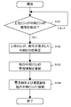
<処理>
以下に本実施形態に係る、ネットワークシステム1の異常発生時の処理を説明する。図2は、異常発生時の処理を説明するフローチャートである。ここでは一例として第1中間ECU21に異常が発生した場合の処理を、図2を参照して説明する。本処理の開始時点では、異常は発生しておらずネットワークシステム1は通常時の動作をしている。この状態では、リレー部41の電源用リレー48および通信用リレー49はいずれも開状態となっている。
<Processing>
Processing when an abnormality occurs in the
(ステップS101):上位ECU11は、いずれかの中間ECUに異常が発生した場合、これを検出することができる。上位ECU11が、いずれかの中間ECUに異常が発生したことを検出した場合、ステップS102に進み、異常が発生したことを検出していない場合、本ステップS101を繰り返す。上位ECU11は、例えば中間ECUからの通信が途絶したり、中間ECUから異常を通知するメッセージを受信したりすること等に基づいて異常発生を検出することができる。
(Step S101): The
(ステップS102):上位ECU11は、検出した異常の内容に基づいて、異常が発生した中間ECUを特定する。ここでは一例として、上位ECU11は、第1中間ECU21を、異常が発生した中間ECUとして特定する。
(Step S102): The
(ステップS103):上位ECU11は、第2中間ECU22の管理情報を更新する。一例として、上位ECU11は、各中間ECUが用いる管理情報をあらかじめ記憶しており、ここでは第1中間ECU21用の第1管理情報を第2中間ECU22に送信する。第2中間ECU22は、受信した第1管理情報とすでに保持している第2管理情報とに基づいて、これらの内容を含む管理情報を新たに用いる管理情報とする。あるいは、他の例として、上位ECU11は、第2中間ECU22に、第1管理情報を新たに管理情報に含める指示を送信してもよい。この場合、第2中間ECU22は、各中間ECUが用いる管理情報をあらかじめ記憶しており、上位ECU11から受信した指示に基づいて、現在用いている第2管理情報に第1管理情報の内容を加えて新たに用いる管理情報とする。
(Step S<b>103 ): The
(ステップS104):上位ECU11は、リレー部41の電源用リレー48を閉状態にして電力線201と電力線202とを接続し、通信用リレー49を閉状態にして通信線211と通信線212とを接続する。なお、リレー部41の制御は上位ECU11ではなく、各中間ECUが行うようにしてもよい。この場合、上位ECU11は正常に動作している第2中間ECU22にリレー部41の電源用リレー48および通信用リレー49を閉状態に制御する指示を送信し、指示を受信した第2中間ECU22が制御を実行する。
(Step S104): The
以上の処理により、第1中間ECU21に異常が発生した場合に、第1中間ECU21の配下の第1下位ECU31を、第2中間ECU22に接続し、これに合わせて、第2中間ECU22が通信管理に用いる管理情報を更新する。これにより、上位ECU11と第1下位ECU31との間の通信中継や第1下位ECU31どうしの通信管理を、第1中間ECU21に代わり、第2中間ECU22が行うことができる。また、第2中間ECU22は、第2下位ECU32と上位ECU11との通信中継や第2下位ECU32どうしの通信管理も継続して行う。
By the above processing, when an abnormality occurs in the first
以上の例では、第1中間ECU21に異常が発生した場合を例にして説明したが、第2中間ECU22に異常が発生した場合も同様の処理によって、上位ECU11と第2下位ECU32との間の通信中継や第2下位ECU32どうしの通信管理を、第2中間ECU22に代わり、第1中間ECU21が行うことができる。このように、1組の中間ECUの一方の異常発生時には、他方が双方の配下の下位ECUの通信管理を行うことができる。
In the above example, the case where an abnormality occurs in the first
(第1変形例)
図3に第1変形例に係るネットワークシステム2の構成図を示す。ネットワークシステム2は、6つの中間ECUを有する。各中間ECUには配下の下位ECUが接続されるが図示を省略する。また、電源、上位ECU11と各中間ECUとを接続する電力線および通信線も図示を省略する。図3に示すように、各中間ECUは一例として車両の各部位に分散して配置される。
(First modification)
FIG. 3 shows a configuration diagram of a network system 2 according to a first modified example. The network system 2 has six intermediate ECUs. Subordinate ECUs are connected to each intermediate ECU, but illustration thereof is omitted. A power supply, power lines and communication lines connecting the
ネットワークシステム2においては、第1中間ECU21とその配下の下位ECUとを接続する電力線201と、第2中間ECU22とその配下の下位ECUとを接続する電力線202とが、リレー部41を介して接続される。また、第1中間ECU21とその配下の下位ECUとを接続する通信線211と、第2中間ECU22とその配下の下位ECUとを接続する通信線212とが、リレー部41を介して接続される。
In the network system 2, a
また、第3中間ECU23とその配下の下位ECUとを接続する電力線203と、第4中間ECU24とその配下の下位ECUとを接続する電力線204とが、リレー部42を介して接続される。また、第3中間ECU23とその配下の下位ECUとを接続する通信線213と、第4中間ECU24とその配下の下位ECUとを接続する通信線214とが、リレー部42を介して接続される。
A
また、第5中間ECU25とその配下の下位ECUとを接続する電力線205と、第6中間ECU26とその配下の下位ECUとを接続する電力線206とが、リレー部43を介して接続される。また、第5中間ECU25とその配下の下位ECUとを接続する通信線215と、第6中間ECU26とその配下の下位ECUとを接続する通信線216とが、リレー部43を介して接続される。
A
ネットワークシステム2においては、第1中間ECU21および第2中間ECU22の組、第3中間ECU23および第4中間ECU24の組、第5中間ECU25および第6中間ECU26の組において、上述の実施形態と同様の処理を行い、各組の一方の異常発生時には他方が、各組の配下の下位ECUの通信管理を行うことができる。
In the network system 2, the set of the first
(第2変形例)
図4に第2変形例に係るネットワークシステム3の構成図を示す。ネットワークシステム3は、ネットワークシステム2において、さらに多くのリレー部を設けたものである。
(Second modification)
FIG. 4 shows a configuration diagram of a network system 3 according to a second modified example. The network system 3 is the network system 2 provided with more relay units.
ネットワークシステム3においては、電力線201と電力線203とが、リレー部44を介して接続される。また、通信線211と、電力線213とが、リレー部44を介して接続される。
In network system 3 ,
また、電力線203と電力線205とが、リレー部45を介して接続される。また、通信線213と、通信線215とが、リレー部45を介して接続される。
Also, the
また、電力線202と電力線204とが、リレー部46を介して接続される。また、通信線212と、通信線214とが、リレー部46を介して接続される。
Also, the
また、電力線204と電力線206とが、リレー部47を介して接続される。また、通信線214と、通信線216とが、リレー部47を介して接続される。
Also,
このように、ネットワークシステム2においては、各中間ECUは、2つの他の中間ECUとの間にリレー部が設けられる。本変形例では、中間ECUの異常発生時の処理を、上述の実施形態の処理から以下のように変更する。以下に変更点を説明する。 Thus, in the network system 2, each intermediate ECU is provided with a relay unit between two other intermediate ECUs. In this modified example, the process when an abnormality occurs in the intermediate ECU is changed from the process of the above-described embodiment as follows. The changes are explained below.
上述の実施形態においては、1組の中間ECUの一方の異常発生時には、一意に定まる他方が代わりとなる、本変形例では、2つの他の中間ECUのいずれかのうち選択した1つが代わりとなる。 In the above-described embodiment, when an abnormality occurs in one of the pair of intermediate ECUs, the other uniquely determined takes its place. Become.
そこで、ステップS103において、上位ECU11は、異常が発生した中間ECUとの間にリレー部が設けられた他の中間ECUのうち、例えば、通信負荷が小さいほうを選択する。通信負荷は、例えば、上位ECU11が、各中間ECUと配下の下位ECUとの間の通信線(バス)のバス負荷を常時監視しておき、直近所定期間のバス負荷に基づいて導出することができる。なお、選択方法はこれに限定されない。ステップS103において、上位ECU11は選択した中間ECUの管理情報を更新し、ステップS104において、異常が発生した中間ECUと選択した中間ECUとの間に設けられたリレー部を制御して、電力線どうしおよび通信線どうしをそれぞれ接続する。例えば、第1中間ECU21に異常が発生した場合、第1中間ECU21との間にリレー部41が設けられた第2中間ECU22およびリレー部44が設けられた第3中間ECU23が選択候補となる。例えば第3中間ECU23の通信負荷が、第2中間ECU22の通信負荷より小さい場合、第3中間ECU23が選択されて、リレー部44によって、第1中間ECU21および第3中間ECU23の電力線どうしおよび通信線どうしが接続され、第3中間ECU23が、第3中間ECU23配下の下位ECUに加えて、第1中間ECU21配下の下位ECUの通信管理を行う。
Therefore, in step S103, the higher-
なお、本変形例において、各中間ECUは、3つ以上の中間ECUとの間にリレー部が設けられてもよい。この場合、ステップS103において、各中間ECUの異常発生時には、3つ以上の中間ECUのうち最も通信負荷の小さいものを選択すればよい。 In addition, in this modification, each intermediate ECU may be provided with a relay unit between three or more intermediate ECUs. In this case, in step S103, when an abnormality occurs in each intermediate ECU, the one with the smallest communication load may be selected from among the three or more intermediate ECUs.
(効果)
実施形態および各変形例に係るネットワークシステム1、2、3は、中間ECUに異常が発生した場合、配下の下位ECUを、リレーを用いて、他の中間ECUに接続し、他の中間ECUが代わりに下位ECUの電力供給や通信の管理を行う。これにより中間ECUの異常発生時においても、下位ECUの機能を継続して発揮させることができる。これにより、ネットワークシステムの堅牢性を高めることができる。
(effect)
In the
また、第2変形例に係るネットワークシステム3のように、異常が発生した中間ECUの配下の下位ECUの通信管理を、複数の中間ECUのうち最も通信負荷の小さいものが行うようにすれば、実施形態や第1変形例に比べて、通信負荷が増えても許容範囲を超えるおそれを低減でき、ネットワークシステムの堅牢性をより高めることができる。 Further, as in the network system 3 according to the second modified example, if communication management of subordinate ECUs subordinate to an abnormal intermediate ECU among a plurality of intermediate ECUs with the lightest communication load is performed, Compared to the embodiment and the first modified example, even if the communication load increases, it is possible to reduce the risk of exceeding the allowable range, and it is possible to further enhance the robustness of the network system.
本発明は、ネットワークシステムだけでなく、ネットワークシステムの制御方法、プロセッサとメモリを備えたECUが実行するネットワークシステムの制御プログラムおよびこれを記憶したコンピュータ読み取り可能な非一時的な記憶媒体、ネットワークシステムを備えた車両等として捉えることが可能である。また、本発明は、車両に搭載されるネットワークシステム以外のネットワークシステムにも適用できる。 The present invention provides not only a network system but also a network system control method, a network system control program executed by an ECU having a processor and a memory, a computer-readable non-temporary storage medium storing the same, and a network system. It is possible to regard it as a vehicle or the like equipped with. The present invention can also be applied to network systems other than those installed in vehicles.
本発明は、車両等に搭載されるネットワークシステムに有用である。 INDUSTRIAL APPLICABILITY The present invention is useful for a network system mounted on a vehicle or the like.
1、2、3 ネットワークシステム
10 電源
11 上位ECU
21 第1中間ECU
22 第2中間ECU
23 第3中間ECU
24 第4中間ECU
25 第5中間ECU
26 第6中間ECU
31 第1下位ECU
32 第2下位ECU
41、42、43、44、45、46、47 リレー部
48 電源用リレー
49 通信用リレー
101、201、202、203、204、205、206 電力線
111、211、212、213、214、215、216 通信線
1, 2, 3 network system 10
21 first intermediate ECU
22 second intermediate ECU
23 third intermediate ECU
24 fourth intermediate ECU
25 fifth intermediate ECU
26 6th intermediate ECU
31 first lower ECU
32 second lower ECU
41, 42, 43, 44, 45, 46, 47
Claims (5)
上位ECUと、
前記電源から電力が供給され、前記上位ECUとそれぞれ通信を行う第1中間ECUおよび第2中間ECUと、
前記第1中間ECUと第1電源経路および第1通信経路で接続され、前記第1中間ECUによって電力供給および通信管理が行われる1以上の第1下位ECUと、
前記第2中間ECUと第2電源経路および第2通信経路で接続され、前記第2中間ECUによって電力供給および通信管理が行われる1以上の第2下位ECUと、
前記第1電源経路および前記第2電源経路の間に設けられた電源用リレーと、
前記第1通信経路および前記第2通信経路の間に設けられた通信用リレーとを備え、
前記上位ECUが前記第1中間ECUの異常発生を検出すると、前記第1電源経路および前記第2電源経路が接続され、かつ、前記第1通信経路および前記第2通信経路が接続されるよう、前記電源用リレーおよび前記通信用リレーが制御されて、前記第1下位ECUの電力供給および通信管理が、前記第2中間ECUによって行われる、車載ネットワークシステム。 a power supply;
high-ranking ECU,
a first intermediate ECU and a second intermediate ECU to which power is supplied from the power source and which respectively communicate with the higher-level ECU;
one or more first subordinate ECUs connected to the first intermediate ECU via a first power supply path and a first communication path, and to which power supply and communication management are performed by the first intermediate ECU;
one or more second lower-level ECUs connected to the second intermediate ECU via a second power supply path and a second communication path and having power supply and communication management performed by the second intermediate ECU;
a power relay provided between the first power supply path and the second power supply path;
a communication relay provided between the first communication path and the second communication path;
so that the first power supply path and the second power supply path are connected and the first communication path and the second communication path are connected when the upper ECU detects the occurrence of an abnormality in the first intermediate ECU; An in-vehicle network system, wherein the power supply relay and the communication relay are controlled, and power supply and communication management of the first lower ECU are performed by the second intermediate ECU.
上位ECUと、
前記電源から電力が供給され、前記上位ECUと通信する複数の中間ECUと、
前記中間ECUのいずれかに電源経路および通信経路を介して接続され、それぞれ接続された前記中間ECUによって電力供給および通信管理が行われる複数の下位ECUと、
各前記中間ECUの電源経路および他の2つ以上の前記中間ECUの電源経路の間にそれぞれ設けられた電源用リレーと、
各前記中間ECUの通信経路および前記他の2つ以上の前記中間ECUの通信経路の間にそれぞれ設けられた通信用リレーとを備え、
前記上位ECUが、いずれかの前記中間ECUの異常発生を検出すると、異常が発生した前記中間ECUと前記他の2つ以上の前記中間ECUから選択された中間ECUとの電源経路どうしおよび通信経路どうしがそれぞれ接続されるように前記電源用リレーおよび前記通信用リレーが制御されて、前記異常が発生した前記中間ECUに接続された前記下位ECUの電力供給および通信管理が、前記選択された中間ECUによって行われる、車載ネットワークシステム。 a power supply;
high-ranking ECU,
a plurality of intermediate ECUs to which power is supplied from the power source and which communicate with the upper ECU;
a plurality of lower-level ECUs connected to any one of the intermediate ECUs via a power supply path and a communication path, wherein power supply and communication management are performed by the respective connected intermediate ECUs;
power supply relays respectively provided between the power supply path of each intermediate ECU and the power supply paths of the other two or more intermediate ECUs;
communication relays respectively provided between the communication path of each intermediate ECU and the communication paths of the other two or more intermediate ECUs;
When the host ECU detects that one of the intermediate ECUs is abnormal, a power supply path and a communication path between the abnormal intermediate ECU and an intermediate ECU selected from the other two or more intermediate ECUs. The power supply relay and the communication relay are controlled so that they are connected to each other, and the power supply and communication management of the lower ECU connected to the abnormal intermediate ECU is controlled by the selected intermediate ECU. In-vehicle network system performed by ECU.
Priority Applications (4)
| Application Number | Priority Date | Filing Date | Title |
|---|---|---|---|
| JP2019127627A JP7120171B2 (en) | 2019-07-09 | 2019-07-09 | In-vehicle network system |
| US16/860,416 US11477047B2 (en) | 2019-07-09 | 2020-04-28 | In-vehicle network system |
| CN202010366750.6A CN112217703B (en) | 2019-07-09 | 2020-04-30 | Vehicle-mounted network system |
| EP20173426.6A EP3764601B1 (en) | 2019-07-09 | 2020-05-07 | In-vehicle network system |
Applications Claiming Priority (1)
| Application Number | Priority Date | Filing Date | Title |
|---|---|---|---|
| JP2019127627A JP7120171B2 (en) | 2019-07-09 | 2019-07-09 | In-vehicle network system |
Publications (2)
| Publication Number | Publication Date |
|---|---|
| JP2021013139A JP2021013139A (en) | 2021-02-04 |
| JP7120171B2 true JP7120171B2 (en) | 2022-08-17 |
Family
ID=70918177
Family Applications (1)
| Application Number | Title | Priority Date | Filing Date |
|---|---|---|---|
| JP2019127627A Active JP7120171B2 (en) | 2019-07-09 | 2019-07-09 | In-vehicle network system |
Country Status (4)
| Country | Link |
|---|---|
| US (1) | US11477047B2 (en) |
| EP (1) | EP3764601B1 (en) |
| JP (1) | JP7120171B2 (en) |
| CN (1) | CN112217703B (en) |
Citations (7)
| Publication number | Priority date | Publication date | Assignee | Title |
|---|---|---|---|---|
| JP2003324497A (en) | 2002-04-26 | 2003-11-14 | Sumitomo Electric Ind Ltd | Communication system and communication control unit |
| JP2004064626A (en) | 2002-07-31 | 2004-02-26 | Denso Corp | Communication system for vehicle |
| JP2007112303A (en) | 2005-10-20 | 2007-05-10 | Toyota Motor Corp | Failure diagnosing system |
| US20110105017A1 (en) | 2008-07-10 | 2011-05-05 | National University Corporation Nagoya University | Relay device, communication system and communication method |
| JP2014113952A (en) | 2012-12-11 | 2014-06-26 | Toyota Motor Corp | In-vehicle system |
| JP2015107672A (en) | 2013-12-03 | 2015-06-11 | 株式会社デンソー | On-vehicle network system |
| JP6205029B1 (en) | 2016-07-29 | 2017-09-27 | シスメックス株式会社 | Specimen transport apparatus, specimen image imaging system, and specimen analysis system |
Family Cites Families (12)
| Publication number | Priority date | Publication date | Assignee | Title |
|---|---|---|---|---|
| JPH06205029A (en) * | 1993-01-06 | 1994-07-22 | Nippon Telegr & Teleph Corp <Ntt> | Information distribution communication system |
| DE602005019499D1 (en) * | 2004-07-15 | 2010-04-08 | Hitachi Ltd | Vehicle control system |
| JP5360967B2 (en) * | 2008-10-08 | 2013-12-04 | 矢崎総業株式会社 | ECU system |
| JP4941500B2 (en) * | 2009-04-17 | 2012-05-30 | 株式会社デンソー | Node device and vehicle network system |
| JP5353545B2 (en) | 2009-08-07 | 2013-11-27 | トヨタ自動車株式会社 | In-vehicle network device |
| CN202480896U (en) * | 2012-01-13 | 2012-10-10 | 浙江吉利汽车研究院有限公司 | Safety redundancy device for automobile power battery system |
| JP5958445B2 (en) * | 2013-10-23 | 2016-08-02 | 株式会社デンソー | In-vehicle network system, management device |
| US9604585B2 (en) * | 2014-07-11 | 2017-03-28 | Ford Global Technologies, Llc | Failure management in a vehicle |
| JP6702214B2 (en) * | 2017-01-31 | 2020-05-27 | トヨタ自動車株式会社 | Power supply and vehicle |
| WO2019021403A1 (en) * | 2017-07-26 | 2019-01-31 | パナソニック インテレクチュアル プロパティ コーポレーション オブ アメリカ | Control network system, vehicle remote control system, and vehicle-mounted relay device |
| JP7119437B2 (en) * | 2018-03-09 | 2022-08-17 | 株式会社デンソー | Vehicle master electronic controller, vehicle slave electronic controller, vehicle log collection system, and vehicle log collection program |
| JP7238650B2 (en) * | 2019-07-09 | 2023-03-14 | トヨタ自動車株式会社 | In-vehicle network system |
-
2019
- 2019-07-09 JP JP2019127627A patent/JP7120171B2/en active Active
-
2020
- 2020-04-28 US US16/860,416 patent/US11477047B2/en active Active
- 2020-04-30 CN CN202010366750.6A patent/CN112217703B/en not_active Expired - Fee Related
- 2020-05-07 EP EP20173426.6A patent/EP3764601B1/en active Active
Patent Citations (8)
| Publication number | Priority date | Publication date | Assignee | Title |
|---|---|---|---|---|
| JP2003324497A (en) | 2002-04-26 | 2003-11-14 | Sumitomo Electric Ind Ltd | Communication system and communication control unit |
| JP2004064626A (en) | 2002-07-31 | 2004-02-26 | Denso Corp | Communication system for vehicle |
| JP2007112303A (en) | 2005-10-20 | 2007-05-10 | Toyota Motor Corp | Failure diagnosing system |
| US20110105017A1 (en) | 2008-07-10 | 2011-05-05 | National University Corporation Nagoya University | Relay device, communication system and communication method |
| JP2014113952A (en) | 2012-12-11 | 2014-06-26 | Toyota Motor Corp | In-vehicle system |
| JP5884716B2 (en) | 2012-12-11 | 2016-03-15 | トヨタ自動車株式会社 | In-vehicle system |
| JP2015107672A (en) | 2013-12-03 | 2015-06-11 | 株式会社デンソー | On-vehicle network system |
| JP6205029B1 (en) | 2016-07-29 | 2017-09-27 | シスメックス株式会社 | Specimen transport apparatus, specimen image imaging system, and specimen analysis system |
Also Published As
| Publication number | Publication date |
|---|---|
| JP2021013139A (en) | 2021-02-04 |
| EP3764601B1 (en) | 2021-11-03 |
| CN112217703B (en) | 2021-12-03 |
| US20210014082A1 (en) | 2021-01-14 |
| CN112217703A (en) | 2021-01-12 |
| EP3764601A1 (en) | 2021-01-13 |
| US11477047B2 (en) | 2022-10-18 |
Similar Documents
| Publication | Publication Date | Title |
|---|---|---|
| EP2713276B1 (en) | Embarked network node module | |
| WO2013136872A1 (en) | In-vehicle communication system | |
| US11249543B2 (en) | In-vehicle control device | |
| JP3912218B2 (en) | Vehicle communication system | |
| JP2017024567A (en) | On-vehicle recording system | |
| JP7201555B2 (en) | In-vehicle network system | |
| JP2018078396A (en) | On-vehicle network system | |
| CN101878618A (en) | Communication device, communication system, and communication method | |
| JP7238650B2 (en) | In-vehicle network system | |
| JP2019153887A (en) | Relay device, communication system, and relay control device | |
| JP7252097B2 (en) | In-vehicle network system | |
| JP7120171B2 (en) | In-vehicle network system | |
| JP2007516905A (en) | Power distribution network node and power management process | |
| CN109691018B (en) | System for energy and/or data transmission | |
| JP7226195B2 (en) | Network system and controller | |
| JP2019200789A (en) | Electronic controller and session establishing program | |
| JP7031568B2 (en) | In-vehicle network system | |
| JP5267199B2 (en) | Relay system and relay method | |
| WO2022158020A1 (en) | Electronic control device, on-vehicle control system, and redundant function control method |
Legal Events
| Date | Code | Title | Description |
|---|---|---|---|
| A621 | Written request for application examination |
Free format text: JAPANESE INTERMEDIATE CODE: A621 Effective date: 20210827 |
|
| A977 | Report on retrieval |
Free format text: JAPANESE INTERMEDIATE CODE: A971007 Effective date: 20220520 |
|
| TRDD | Decision of grant or rejection written | ||
| A01 | Written decision to grant a patent or to grant a registration (utility model) |
Free format text: JAPANESE INTERMEDIATE CODE: A01 Effective date: 20220705 |
|
| A61 | First payment of annual fees (during grant procedure) |
Free format text: JAPANESE INTERMEDIATE CODE: A61 Effective date: 20220718 |
|
| R151 | Written notification of patent or utility model registration |
Ref document number: 7120171 Country of ref document: JP Free format text: JAPANESE INTERMEDIATE CODE: R151 |