US8456748B2 - Zoom lens system and electronic imaging apparatus using the same - Google Patents
Zoom lens system and electronic imaging apparatus using the same Download PDFInfo
- Publication number
- US8456748B2 US8456748B2 US13/291,624 US201113291624A US8456748B2 US 8456748 B2 US8456748 B2 US 8456748B2 US 201113291624 A US201113291624 A US 201113291624A US 8456748 B2 US8456748 B2 US 8456748B2
- Authority
- US
- United States
- Prior art keywords
- lens group
- lens
- focal length
- negative
- designates
- Prior art date
- Legal status (The legal status is an assumption and is not a legal conclusion. Google has not performed a legal analysis and makes no representation as to the accuracy of the status listed.)
- Active, expires
Links
Images


Classifications
-
- G—PHYSICS
- G02—OPTICS
- G02B—OPTICAL ELEMENTS, SYSTEMS OR APPARATUS
- G02B15/00—Optical objectives with means for varying the magnification
- G02B15/14—Optical objectives with means for varying the magnification by axial movement of one or more lenses or groups of lenses relative to the image plane for continuously varying the equivalent focal length of the objective
- G02B15/16—Optical objectives with means for varying the magnification by axial movement of one or more lenses or groups of lenses relative to the image plane for continuously varying the equivalent focal length of the objective with interdependent non-linearly related movements between one lens or lens group, and another lens or lens group
- G02B15/177—Optical objectives with means for varying the magnification by axial movement of one or more lenses or groups of lenses relative to the image plane for continuously varying the equivalent focal length of the objective with interdependent non-linearly related movements between one lens or lens group, and another lens or lens group having a negative front lens or group of lenses
-
- G—PHYSICS
- G02—OPTICS
- G02B—OPTICAL ELEMENTS, SYSTEMS OR APPARATUS
- G02B15/00—Optical objectives with means for varying the magnification
- G02B15/14—Optical objectives with means for varying the magnification by axial movement of one or more lenses or groups of lenses relative to the image plane for continuously varying the equivalent focal length of the objective
- G02B15/143—Optical objectives with means for varying the magnification by axial movement of one or more lenses or groups of lenses relative to the image plane for continuously varying the equivalent focal length of the objective having three groups only
- G02B15/1435—Optical objectives with means for varying the magnification by axial movement of one or more lenses or groups of lenses relative to the image plane for continuously varying the equivalent focal length of the objective having three groups only the first group being negative
- G02B15/143503—Optical objectives with means for varying the magnification by axial movement of one or more lenses or groups of lenses relative to the image plane for continuously varying the equivalent focal length of the objective having three groups only the first group being negative arranged -+-
Definitions
- the present invention relates to a zoom lens system and an electronic imaging apparatus using the same.
- lens-shutter zoom lens systems which pursue miniaturization have also been proposed, however, the incidence-angle of light that is incident on the imaging surface is not sufficiently perpendicular to the imaging surface (i.e., has poor telecentricity), so that use of such lens-shutter zoom lens systems with a digital imaging sensor is not realistic.
- a zoom lens system which has three lens groups, i.e., a negative first lens group, a positive second lens group, and a negative third lens group, in that order from the object side, for use with an image sensor having a large APS size.
- the third lens group it is typical for the third lens group to be configured of two lens elements, i.e., a negative lens element and a positive lens element, in that order from the object side, or a positive lens element and a negative lens element, in that order from the object side. Examples of the latter arrangement of the third lens group can be found in Japanese Unexamined Patent Publication Nos. 2001-290076, 2002-221660 and 2009-25534.
- the former zoom lens system in which the third lens group is configured of a negative lens element and a positive lens element, in that order from the object side, is advantageous for improving telecentricity, various aberrations such as lateral chromatic aberration, astigmatism, distortion and spherical aberration that occur in the negative first lens group cannot be favorable corrected.
- the negative lens element on the object side within the third lens group and the positive lens element on the image side within the third lens group constitute a local retrofocus lens arrangement, an increase in the overall length of the zoom lens system cannot be avoided.
- the third lens group is configured of a positive lens element and a negative lens element
- the refractive power of the negative lens element on the image side needs to be increased, so that the refractive-power balance between the positive lens element on the object side and the negative lens element on the image side is not favorable.
- the present invention provides a zoom lens system configured of three lens groups, i.e., a negative lens group, a positive lens group and a negative lens group, in that order from the object side, which uses, e.g., a large APS-sized image sensor while achieving compact zoom lens system that has a superior optical quality; furthermore, the present invention also provides an electronic imaging apparatus which utilizes such a zoom lens system.
- a zoom lens system including a negative first lens group, a positive second lens group, and a negative third lens group, in that order from the object side, wherein upon zooming from the short focal length extremity to the long focal length extremity, the distance between the first lens group and the second lens group decreases.
- the third lens group includes a negative lens element having a concave surface on the image side, a positive lens element having a convex surface on the image side, and a negative lens element having convex surface on the image side, in that order from the object side.
- condition (1) 0.8 ⁇ f 3 a/f 3 c ⁇ 3.0 (1), wherein f3 a designates the focal length of the negative lens element which is provided closest to the object side within the third lens group, and f 3 c designates the focal length of the negative lens element which is provided closest to the image side within the third lens group.
- the third lens group prefferably includes a focusing lens group which is moved along the optical axis direction during focusing, wherein the following condition (2) is satisfied: 0.65 ⁇ Z 3 /Z ⁇ 0.80 (2), wherein
- m 3 t designates the lateral magnification of the third lens group at the long focal length extremity when focused on an object at infinity
- m 3 w designates the lateral magnification of the third lens group at the short focal length extremity when focused on an object at infinity
- ft designates the focal length of the entire the zoom lens system at the long focal length extremity
- fw designates the focal length of the entire the zoom lens system at the short focal length extremity.
- an electronic imaging apparatus including the above-described zoom lens system, and an image sensor which converts an image formed by the zoom lens system into electrical signals.
- a zoom lens system configured of three lens groups, i.e., a negative lens group, a positive lens group and a negative lens group, in that order from the object side, is achieved which uses, e.g., a large APS-sized image sensor while achieving compact zoom lens system that has a superior optical quality; furthermore, the present invention also provides an electronic imaging apparatus which utilizes such a zoom lens system.
- FIG. 1 shows a lens arrangement of a first numerical embodiment of a zoom lens system, according to the present invention, at the long focal length extremity when focused on an object at infinity;
- FIGS. 2A , 2 B, 2 C and 2 D show various aberrations that occurred in the lens arrangement shown in FIG. 1 ;
- FIG. 3 shows a lens arrangement of the first numerical embodiment of the zoom lens system, according to the present invention, at the short focal length extremity when focused on an object at infinity;
- FIGS. 4A , 4 B, 4 C and 4 D show various aberrations that occurred in the lens arrangement shown in FIG. 3 ;
- FIG. 5 shows a lens arrangement of a second numerical embodiment of a zoom lens system, according to the present invention, at the long focal length extremity when focused on an object at infinity;
- FIGS. 6A , 6 B, 6 C and 6 D show various aberrations that occurred in the lens arrangement shown in FIG. 5 ;
- FIG. 7 shows a lens arrangement of the second numerical embodiment of the zoom lens system, according to the present invention, at the short focal length extremity when focused on an object at infinity;
- FIGS. 8A , 8 B, 8 C and 8 D show various aberrations that occurred in the lens arrangement shown in FIG. 7 ;
- FIG. 9 shows a lens arrangement of a third numerical embodiment of a zoom lens system, according to the present invention, at the long focal length extremity when focused on an object at infinity;
- FIGS. 10A , 10 B, 10 C and 10 D show various aberrations that occurred in the lens arrangement shown in FIG. 9 ;
- FIG. 11 shows a lens arrangement of the third numerical embodiment of the zoom lens system, according to the present invention, at the short focal length extremity when focused on an object at infinity;
- FIGS. 12A , 12 B, 12 C and 12 D show various aberrations that occurred in the lens arrangement shown in FIG. 11 ;
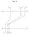
- FIG. 13 shows a zoom path of the zoom lens system according to the present invention.
- the zoom lens system according to the present invention is configured of a negative first lens group G 1 , a positive second lens group G 2 and a negative third lens group G 3 , in that order from the object side.
- a diaphragm S which is provided in between the first lens group G 1 and the second lens group G 2 moves integrally with the second lens group G 2 during zooming.
- ‘I’ designates the imaging plane.
- the third lens group G 3 constitutes a focusing lens group which is moved during a focusing operation (the third lens group G 3 is advanced toward the image side upon carrying out a focusing operation on an object at infinity to an object at a finite distance).
- the zoom lens system upon zooming from the short focal length extremity (WIDE) to the long focal length extremity (TELE), moves the first through third lens groups G 1 through G 3 in the optical axis direction while reducing the distance between the first and second lens groups G 1 and G 2 , and reducing the distance between the second and third lens groups G 2 and G 3 .
- the first through third lens groups G 1 through G 3 each move monotonically toward the object side.
- the first lens group G 1 is configured of a negative lens element 11 and a positive lens element 12 , in that order from the object side.
- the second lens group G 2 is configured of a cemented lens formed from a positive lens element 21 and a negative lens element 22 ; and a positive lens element 23 , in that order from the object side.
- the positive lens element 23 has an aspherical surface on each side thereof.
- the third lens group G 3 is configured of a negative lens element (a negative lens element having a concave surface on the image side) 31 , a positive lens element (a positive lens element having a convex surface on the image side) 32 , and a negative lens element (a negative lens element having a convex surface on the image side) 33 , in that order from the object side.
- the negative lens element 31 has an aspherical surface on the object side thereof.
- the positive lens element 32 has an aspherical surface on both sides thereof, whereas in the third numerical embodiment, the positive lens element 32 has an aspherical surface only on the image side thereof.
- the zoom lens system of the present invention constitutes a retrofocus lens system at the short focal length extremity having a negative front lens group (first lens group G 1 ) and a positive rear lens group (second and third lens groups G 2 and G 3 ), thereby improving telecentricity of the zoom lens system; and constitutes a telephoto lens system at the long focal length extremity having a positive front lens group (first and second lens groups G 1 and G 2 ) and a negative rear lens group (third lens group G 3 ), thereby reducing the overall length of the zoom lens system.
- this lens arrangement both an improvement in the telecentricity and a reduced overall length of the zoom lens system can both be achieved.
- the negative third lens group G 3 In order to improve the telecentricity of the zoom lens system, it is appropriate to configure the negative third lens group G 3 of a negative lens element and a positive lens element, in that order from the object side.
- the third lens group G 3 is only configured of two lens elements, i.e., a negative lens element and a positive lens element, in that order from the object side, the various aberrations that occur in the first lens group G 1 such as lateral chromatic aberration, astigmatism, distortion and spherical aberration, etc., cannot be favorably corrected.
- the zoom lens system by providing a negative lens element ( 33 ) closest to the image side within the third lens group G 3 , and configuring the third lens group G 3 so as to have three lens elements, i.e., a negative lens element, a positive lens element and a negative lens element, in that order from the object side, the telecentricity can be improved while the various remaining aberrations that occurred at the first lens group G 1 can be favorably corrected by the third lens group G 3 .
- the third lens group G 3 is configured of the following three lens elements: a negative lens element having a concave surface on the image side, a positive lens element having a convex surface on the image side, and a negative lens element having a convex surface on the image side, in that order from the object side, as in the numerical embodiments of the zoom lens system.
- Condition (1) specifies the ratio of the focal length of the negative lens element 31 provided closest to the object side within the third lens group G 3 to the focal length of the negative lens element 33 provided closest to the image side within the third lens group G 3 , and is for improving the telecentricity of the zoom lens system while also correcting the various aberrations that occurred at the first lens group G 1 .
- the refractive power of the negative lens element 33 that is provided closest to the image side within the third lens group G 3 becomes too strong, which is advantageous for correcting various aberrations that occurred at the first lens group G 1 , however, it becomes difficult to maintain telecentricity.
- the refractive power of the negative lens element 31 that is provided closest to the object side within the third lens group G 3 becomes too strong, which is advantageous for improving telecentricity, however, it becomes difficult to correct the various aberrations that occurred at the first lens group G 1 .
- the third lens group G 3 constitutes a focusing lens group which is moved along the optical axis during a focusing operation.
- condition (2) specifies the proportion of the ratio of the lateral magnification of the third lens group G 3 at the long focal length extremity when focused on an object at infinity to the lateral magnification of the third lens group G 3 at the short focal length extremity when focused on an object at infinity (i.e., the zoom ratio of the third lens group G 3 ), to the ratio of the focal length of the entire zoom lens system, at the long focal length extremity to the focal length of the entire zoom lens system at the short focal length extremity.
- condition (2) the change in the zoom ratio of the entire zoom lens system can be made to coincide with the change of focusing sensitivity of the third lens group G 3 , which constitutes a focusing lens group, so that a focal shift which would otherwise occur during zooming can be prevented.
- condition (2) If either the upper or lower limits of condition (2) is exceeded, the focal shift during zooming increases.
- Condition (3) specifies the ratio of the focal length of the first lens group G 1 to the focal length of the third lens group G 3 , and is for achieving both an improvement of telecentricity and further miniaturization of the zoom lens system.
- the refractive power of the third lens group G 3 becomes too strong, which is advantageous for miniaturization, however, the telecentricity undesirably deteriorates.
- Condition (4) specifies the ratio of the focal length of the second lens group G 2 to the focal length of the third lens group G 3 , and is for both correcting aberrations and improving telecentricity.
- the refractive power of the second lens group G 2 becomes too strong, so that it becomes difficult to correct spherical aberration and coma, especially at the long focal length extremity.
- the following numerical embodiments are applied to a zoom lens system used in a digital camera.
- the d-line, the g-line and the C-line show aberrations at their respective wave-lengths;
- S designates the sagittal image,
- M designates the meridional image, FNO.
- f-number designates the f-number
- f designates the focal length of the entire optical system
- W designates the half angle of view (°)
- Y designates the image height
- fB designates the backfocus
- L designates the overall length of the lens system
- r designates the radius of curvature
- d designates the lens thickness or distance between lenses
- N(d) designates the refractive index at the d-line
- vd designates the Abbe number with respect to the d-line.
- the values for the f-number, the focal length, the half angle-of-view, the image height, the backfocus, the overall length of the lens system, and the distance between lenses (which changes during zooming) are shown in the following order: short focal length extremity, intermediate focal length, and long focal length extremity.
- ‘x’ designates a distance from a tangent plane of the aspherical vertex
- ‘c’ designates the curvature (1/r) of the aspherical vertex
- ‘y’ designates the distance from the optical axis
- ‘K’ designates the conic coefficient
- A4 designates a fourth-order aspherical coefficient
- A6 designates a sixth-order aspherical coefficient
- A8 designates an eighth-order aspherical coefficient
- A10 designates a tenth-order aspherical coefficient
- A12 designates a twelfth-order aspherical coefficient.
- FIGS. 1 through 4D and Tables 1 through 4 show a first numerical embodiment of a zoom lens system according to the present invention.
- FIG. 1 shows a lens arrangement of the first numerical embodiment of the zoom lens system at the long focal length extremity when focused on an object at infinity.
- FIGS. 2A , 2 B, 2 C and 2 D show various aberrations that occurred in the lens arrangement shown in FIG. 1 .
- FIG. 3 shows a lens arrangement of the first numerical embodiment of the zoom lens system at the short focal length extremity when focused on an object at infinity.
- FIGS. 4A , 4 B, 4 C and 4 D show various aberrations that occurred in the lens arrangement shown in FIG. 3 .
- Table 1 shows the lens surface data
- Table 2 shows various zoom lens system data
- Table 3 shows the aspherical surface data
- Table 4 shows the lens group data of the zoom lens system according to the first numerical embodiment.
- the zoom lens system of the first numerical embodiment is configured of a negative first lens group G 1 , a positive second lens group G 2 and a negative third lens group G 3 , in that order from the object side.
- the third lens group G 3 constitutes a focusing lens group that is moved along the optical axis direction during a focusing operation (the third lens group G 3 advances toward the image side when performing a focusing operation while focusing on an object at infinity to an object at a finite distance).
- the first lens group G 1 (surface Nos. 1 through 4 ) is configured of a biconcave negative lens element 11 and a positive meniscus lens element 12 having a convex surface on the object side, in that order from the object side.
- the second lens group G 2 (surface Nos. 6 through 10 ) is configured of a cemented lens formed from a biconvex positive lens element 21 and a negative meniscus lens element 22 having a convex surface on the image side; and a biconvex positive lens element 23 , in that order from the object side.
- the biconvex positive lens element 23 has an aspherical surface on each side thereof.
- a diaphragm S (surface No. 5 ), which is provided in between the first lens group G 1 and the second lens group G 2 , integrally moves with the second lens group G 2 along the optical axis during zooming.
- the third lens group G 3 (surface Nos. 11 through 16 ) is configured of a biconcave negative lens element (a negative lens element having a concave surface on the image side) 31 , a positive meniscus lens element (a positive lens element having a convex surface on the image side) 32 having a convex surface on the image side, and a negative meniscus lens element (a negative lens element having a convex surface on the image side) 33 having a convex surface on the image side, in that order from the object side.
- the biconcave negative lens element 31 has an aspherical surface on the object side.
- the positive meniscus lens element 32 has an aspherical surface on each side thereof.
- An optical filter OP (surface Nos. 17 and 18 ) is disposed behind (between the third lens group G 3 and the imaging plane I) the third lens group G 3 (the negative meniscus lens element 33 ).
- FIGS. 5 through 8D and Tables 5 through 8 show a second numerical embodiment of a zoom lens system according to the present invention.
- FIG. 5 shows a lens arrangement of the second numerical embodiment of the zoom lens system at the long focal length extremity when focused on an object at infinity.
- FIGS. 6A , 6 B, 6 C and 6 D show various aberrations that occurred in the lens arrangement shown in FIG. 5 .
- FIG. 7 shows a lens arrangement of the second numerical embodiment of the zoom lens system at the short focal length extremity when focused on an object at infinity.
- FIGS. 8A , 8 B, 8 C and 8 D show various aberrations that occurred in the lens arrangement shown in FIG. 7 .
- Table 5 shows the lens surface data
- Table 6 shows various zoom lens system data
- Table 7 shows the aspherical surface data
- Table 8 shows the lens group data of the zoom lens system according to the second numerical embodiment.
- FIGS. 9 through 12D and Tables 9 through 12 show a third numerical embodiment of a zoom lens system according to the present invention.
- FIG. 9 shows a lens arrangement of the third numerical embodiment of the zoom lens system at the long focal length extremity when focused on an object at infinity.
- FIGS. 10A , 10 B, 10 C and 10 D show various aberrations that occurred in the lens arrangement shown in FIG. 9 .
- FIG. 11 shows a lens arrangement of the third numerical embodiment of the zoom lens system at the short focal length extremity when focused on an object at infinity.
- FIGS. 12A , 12 B, 12 C and 12 D show various aberrations that occurred in the lens arrangement shown in FIG. 11 .
- Table 9 shows the lens surface data
- Table 10 shows various zoom lens system data
- Table 11 shows the aspherical surface data
- Table 12 shows the lens group data of the zoom lens system according to the third numerical embodiment.
- the first through third numerical embodiments satisfy conditions (1) through (4). Furthermore, as can be understood from the aberration diagrams, the various aberrations are suitably corrected.
Landscapes
- Physics & Mathematics (AREA)
- General Physics & Mathematics (AREA)
- Optics & Photonics (AREA)
- Nonlinear Science (AREA)
- Lenses (AREA)
Applications Claiming Priority (2)
| Application Number | Priority Date | Filing Date | Title |
|---|---|---|---|
| JP2010-256911 | 2010-11-17 | ||
| JP2010256911A JP5615674B2 (ja) | 2010-11-17 | 2010-11-17 | ズームレンズ系及びこれを用いた電子撮像装置 |
Publications (2)
| Publication Number | Publication Date |
|---|---|
| US20120120503A1 US20120120503A1 (en) | 2012-05-17 |
| US8456748B2 true US8456748B2 (en) | 2013-06-04 |
Family
ID=46047535
Family Applications (1)
| Application Number | Title | Priority Date | Filing Date |
|---|---|---|---|
| US13/291,624 Active 2032-01-03 US8456748B2 (en) | 2010-11-17 | 2011-11-08 | Zoom lens system and electronic imaging apparatus using the same |
Country Status (2)
| Country | Link |
|---|---|
| US (1) | US8456748B2 (ja) |
| JP (1) | JP5615674B2 (ja) |
Cited By (1)
| Publication number | Priority date | Publication date | Assignee | Title |
|---|---|---|---|---|
| US20140300781A1 (en) * | 2013-04-03 | 2014-10-09 | Canon Kabushiki Kaisha | Zoom lens and image pickup apparatus including the same |
Families Citing this family (4)
| Publication number | Priority date | Publication date | Assignee | Title |
|---|---|---|---|---|
| JP2012108306A (ja) * | 2010-11-17 | 2012-06-07 | Hoya Corp | ズームレンズ系及びこれを用いた電子撮像装置 |
| CN111929871B (zh) * | 2020-09-21 | 2020-12-18 | 常州市瑞泰光电有限公司 | 摄像光学镜头 |
| CN112230404B (zh) * | 2020-10-28 | 2022-10-11 | Oppo广东移动通信有限公司 | 光学变焦镜头、摄像模组及移动终端 |
| WO2023207204A1 (zh) * | 2022-04-25 | 2023-11-02 | Oppo广东移动通信有限公司 | 变焦镜头、摄像头模组及电子设备 |
Citations (4)
| Publication number | Priority date | Publication date | Assignee | Title |
|---|---|---|---|---|
| JP2001290076A (ja) | 2000-04-05 | 2001-10-19 | Nikon Corp | 可変焦点距離レンズ系 |
| JP2002221660A (ja) | 2001-01-24 | 2002-08-09 | Asahi Optical Co Ltd | ズームレンズ系 |
| JP2009025534A (ja) | 2007-07-19 | 2009-02-05 | Konica Minolta Opto Inc | 変倍光学系、撮像装置およびデジタル機器 |
| US20120120502A1 (en) * | 2010-11-17 | 2012-05-17 | Hoya Corporation | Zoom lens system and electronic imaging apparatus using the same |
Family Cites Families (2)
| Publication number | Priority date | Publication date | Assignee | Title |
|---|---|---|---|---|
| JPH03212608A (ja) * | 1990-01-18 | 1991-09-18 | Konica Corp | ズームレンズ |
| JPH03212607A (ja) * | 1990-01-18 | 1991-09-18 | Konica Corp | ズームレンズ |
-
2010
- 2010-11-17 JP JP2010256911A patent/JP5615674B2/ja not_active Expired - Fee Related
-
2011
- 2011-11-08 US US13/291,624 patent/US8456748B2/en active Active
Patent Citations (5)
| Publication number | Priority date | Publication date | Assignee | Title |
|---|---|---|---|---|
| JP2001290076A (ja) | 2000-04-05 | 2001-10-19 | Nikon Corp | 可変焦点距離レンズ系 |
| JP2002221660A (ja) | 2001-01-24 | 2002-08-09 | Asahi Optical Co Ltd | ズームレンズ系 |
| US20020141073A1 (en) | 2001-01-24 | 2002-10-03 | Asahi Kogaku Kogyo Kabushiki Kaisha | Zoom lens system |
| JP2009025534A (ja) | 2007-07-19 | 2009-02-05 | Konica Minolta Opto Inc | 変倍光学系、撮像装置およびデジタル機器 |
| US20120120502A1 (en) * | 2010-11-17 | 2012-05-17 | Hoya Corporation | Zoom lens system and electronic imaging apparatus using the same |
Non-Patent Citations (1)
| Title |
|---|
| U.S. Appl. No. 13/291,612 to Masakazu Saori, filed Nov. 8, 2011. |
Cited By (2)
| Publication number | Priority date | Publication date | Assignee | Title |
|---|---|---|---|---|
| US20140300781A1 (en) * | 2013-04-03 | 2014-10-09 | Canon Kabushiki Kaisha | Zoom lens and image pickup apparatus including the same |
| US9148575B2 (en) * | 2013-04-03 | 2015-09-29 | Canon Kabushiki Kaisha | Zoom lens and image pickup apparatus including the same |
Also Published As
| Publication number | Publication date |
|---|---|
| US20120120503A1 (en) | 2012-05-17 |
| JP5615674B2 (ja) | 2014-10-29 |
| JP2012108305A (ja) | 2012-06-07 |
Similar Documents
| Publication | Publication Date | Title |
|---|---|---|
| US8605365B2 (en) | Zoom lens system | |
| US8325427B2 (en) | Zoom lens system | |
| US7715116B2 (en) | Telephoto lens system | |
| US7324293B2 (en) | Wide-angle lens system | |
| US8208207B2 (en) | Zoom lens system | |
| US7253966B2 (en) | Zoom lens system | |
| US7808720B2 (en) | Standard zoom lens system | |
| US20070263295A1 (en) | Zoom lens system | |
| US7230772B2 (en) | Wide-angle zoom lens system | |
| US7411746B2 (en) | Wide-angle lens system | |
| US7248416B2 (en) | Wide-angle zoom lens system | |
| US9874734B2 (en) | Zoom optical system and imaging apparatus provided with the same | |
| US8169720B2 (en) | Rear focus wide-angle lens system and electronic imaging device using the same | |
| US8531768B2 (en) | Zoom lens system | |
| US8514495B2 (en) | Zoom lens system | |
| US20080297914A1 (en) | Zoom lens system | |
| US7106520B2 (en) | Wide-angle zoom lens system | |
| US7843651B2 (en) | Wide-angle lens system | |
| US8553328B2 (en) | Zoom lens system | |
| US8248703B2 (en) | Zoom lens and optical apparatus having the zoom lens | |
| JP2013130676A (ja) | ズームレンズおよびそれを有する撮像装置 | |
| US8456748B2 (en) | Zoom lens system and electronic imaging apparatus using the same | |
| US8908298B2 (en) | Zoom lens system and electronic imaging apparatus using the same | |
| US9097882B2 (en) | Zoom lens system | |
| US20120063004A1 (en) | Zoom lens system |
Legal Events
| Date | Code | Title | Description |
|---|---|---|---|
| AS | Assignment |
Owner name: HOYA CORPORATION, JAPAN Free format text: ASSIGNMENT OF ASSIGNORS INTEREST;ASSIGNOR:SAORI, MASAKAZU;REEL/FRAME:027194/0202 Effective date: 20111102 |
|
| STCF | Information on status: patent grant |
Free format text: PATENTED CASE |
|
| FEPP | Fee payment procedure |
Free format text: PAYOR NUMBER ASSIGNED (ORIGINAL EVENT CODE: ASPN); ENTITY STATUS OF PATENT OWNER: LARGE ENTITY |
|
| FPAY | Fee payment |
Year of fee payment: 4 |
|
| MAFP | Maintenance fee payment |
Free format text: PAYMENT OF MAINTENANCE FEE, 8TH YEAR, LARGE ENTITY (ORIGINAL EVENT CODE: M1552); ENTITY STATUS OF PATENT OWNER: LARGE ENTITY Year of fee payment: 8 |