US8456674B2 - Printing process model predictive control with disturbance preview - Google Patents
Printing process model predictive control with disturbance preview Download PDFInfo
- Publication number
- US8456674B2 US8456674B2 US12/603,674 US60367409A US8456674B2 US 8456674 B2 US8456674 B2 US 8456674B2 US 60367409 A US60367409 A US 60367409A US 8456674 B2 US8456674 B2 US 8456674B2
- Authority
- US
- United States
- Prior art keywords
- print media
- data
- image
- reproduction machine
- image reproduction
- Prior art date
- Legal status (The legal status is an assumption and is not a legal conclusion. Google has not performed a legal analysis and makes no representation as to the accuracy of the status listed.)
- Expired - Fee Related, expires
Links
Images


Classifications
-
- G—PHYSICS
- G03—PHOTOGRAPHY; CINEMATOGRAPHY; ANALOGOUS TECHNIQUES USING WAVES OTHER THAN OPTICAL WAVES; ELECTROGRAPHY; HOLOGRAPHY
- G03G—ELECTROGRAPHY; ELECTROPHOTOGRAPHY; MAGNETOGRAPHY
- G03G15/00—Apparatus for electrographic processes using a charge pattern
- G03G15/20—Apparatus for electrographic processes using a charge pattern for fixing, e.g. by using heat
- G03G15/2003—Apparatus for electrographic processes using a charge pattern for fixing, e.g. by using heat using heat
- G03G15/2014—Apparatus for electrographic processes using a charge pattern for fixing, e.g. by using heat using heat using contact heat
- G03G15/2064—Apparatus for electrographic processes using a charge pattern for fixing, e.g. by using heat using heat using contact heat combined with pressure
-
- G—PHYSICS
- G03—PHOTOGRAPHY; CINEMATOGRAPHY; ANALOGOUS TECHNIQUES USING WAVES OTHER THAN OPTICAL WAVES; ELECTROGRAPHY; HOLOGRAPHY
- G03G—ELECTROGRAPHY; ELECTROPHOTOGRAPHY; MAGNETOGRAPHY
- G03G15/00—Apparatus for electrographic processes using a charge pattern
- G03G15/20—Apparatus for electrographic processes using a charge pattern for fixing, e.g. by using heat
- G03G15/2003—Apparatus for electrographic processes using a charge pattern for fixing, e.g. by using heat using heat
- G03G15/2014—Apparatus for electrographic processes using a charge pattern for fixing, e.g. by using heat using heat using contact heat
- G03G15/2039—Apparatus for electrographic processes using a charge pattern for fixing, e.g. by using heat using heat using contact heat with means for controlling the fixing temperature
-
- G—PHYSICS
- G03—PHOTOGRAPHY; CINEMATOGRAPHY; ANALOGOUS TECHNIQUES USING WAVES OTHER THAN OPTICAL WAVES; ELECTROGRAPHY; HOLOGRAPHY
- G03G—ELECTROGRAPHY; ELECTROPHOTOGRAPHY; MAGNETOGRAPHY
- G03G15/00—Apparatus for electrographic processes using a charge pattern
- G03G15/50—Machine control of apparatus for electrographic processes using a charge pattern, e.g. regulating differents parts of the machine, multimode copiers, microprocessor control
- G03G15/5029—Machine control of apparatus for electrographic processes using a charge pattern, e.g. regulating differents parts of the machine, multimode copiers, microprocessor control by measuring the copy material characteristics, e.g. weight, thickness
-
- G—PHYSICS
- G03—PHOTOGRAPHY; CINEMATOGRAPHY; ANALOGOUS TECHNIQUES USING WAVES OTHER THAN OPTICAL WAVES; ELECTROGRAPHY; HOLOGRAPHY
- G03G—ELECTROGRAPHY; ELECTROPHOTOGRAPHY; MAGNETOGRAPHY
- G03G2215/00—Apparatus for electrophotographic processes
- G03G2215/00362—Apparatus for electrophotographic processes relating to the copy medium handling
- G03G2215/00789—Adding properties or qualities to the copy medium
- G03G2215/00805—Gloss adding or lowering device
Definitions
- This disclosure relates in general to copier/printers, and more particularly, to printing systems for monitoring and controlling with a model predictive controller (MPC) and more specifically to tuning the MPC controller in the face of disturbance preview.
- MPC model predictive controller
- Modern printers and copiers employ many control systems to achieve higher performance through varying control logic schemes.
- Example control systems include media transport control, marking process control, fuser temperature control and the like.
- Various control logic schemes are known that implicitly affect a tradeoff of performance and print parameters. However, these tradeoffs are built-in and cannot be varied on the fly. Some systems have the ability to switch between a normal run mode and specific operating modes, but they are simply either “ON” or “OFF.” The system cannot choose a varying level of functions or tailor specific functions for a specific component that is based on disturbances in the print process.
- a disturbance preview is when the condition of the disturbance dynamics is known and available in advance.
- a disturbance preview provides an opportunity for optimizing the print process by trading current performance for better overall performance. Before the impact of an impending disturbance, the state of the system may be driven out of the optimal region for current performance and enter a fast recovery region in preparation for the disturbance impact.
- conventional control systems in printing process do not take advantage of disturbance preview.
- the disclosure relates generally to methods and systems that incorporate a model predictive controller (MPC) in an image reproduction machine with known disturbance information.
- MPC uses the control action at a current time in order to minimize the impact of an impending disturbance as well as to maximize current control performance.
- the impending disturbance is used by the MPC to determine an incremental change that combines steady state and transient state impact on the image reproduction machine.
- Disturbance such as print media type, image content type, physical dimension of the print media, weight of the print media, and print job data can be employed.
- control of the image reproduction machine is generated in real time over a receding horizon, for the purpose of minimizing a cost function indicative of image variation, energy consumption, or the like.
- FIG. 1 is a schematic elevational view of an exemplary image reproduction machine including a fusing apparatus having a dynamic model predictive controller in accordance to an embodiment
- FIG. 2 is a block diagram of a dynamic model predictive controller of FIG. 1 in accordance to an embodiment
- FIG. 3 is an enlarged end section schematic of the roller assembly of the fusing apparatus of FIG. 1 in accordance to an embodiment
- FIG. 4 is an illustration of start-of-job transient performance using dynamic model predictive control with disturbance preview in accordance to an embodiment
- FIG. 5 is an illustration of end-of-job transient performance using dynamic model predictive control with disturbance preview in accordance to an embodiment
- FIG. 6 is an illustration of variable manipulation during a control horizon in accordance to an embodiment
- FIG. 7 illustrates the structure and functions performed by a dynamic model predictive controller of an image reproduction machine in accordance to an embodiment
- FIG. 8 is a flowchart of a method in a process control system having a dynamic model predictive controller to provide control to an image reproduction machine in accordance to an embodiment
- FIG. 9 is a flowchart outlining one exemplary embodiment of the operation of the dynamic model predictive controller over a defined horizon in accordance to an embodiment.
- aspects of the disclosed embodiments relate to an apparatus using dynamic model predictive control to mitigate the effects of known disturbance in the printing process to control an image reproduction machine such as a printer or a copier.
- the control action at current time step impact of an impending disturbance is minimized while current control performance is maximized.
- the dynamic model predictive control is demonstrated by applying the technique to a fuser temperature control.
- the disclosed embodiments include an image reproduction machine with a moveable imaging member including an imaging surface; an imaging system to form and transfer an image from the imaging surface onto a print media; a fusing system to apply a fusing treatment to an image applied to the print media, wherein the fusing system includes a heated rotating fuser member and a rotating pressure member forming a fusing nip with said heated rotating fuser member; an interface to receive sensing data and to acquire at least one disturbance preview; and a dynamic model predictive controller to control the image reproduction machine based on the sensed data and the at least one disturbance preview.
- the dynamic model predictive controller determines an incremental change that combines steady state and transient state impact on the image reproduction machine.
- control of the image reproduction machine is generated in real time over a receding horizon, for the purpose of minimizing a cost function.
- Examples of disturbance can be selected from print media type, image content type, coated print media, uncoated print media, physical dimension of the print media, weight of the print media, print job data.
- the disclosed embodiments further include a method in a process control system having a dynamic model predictive controller to provide control to an image reproduction machine with a plurality of variables and at least one disturbance variable by performing the action of forming and transferring an image from an imaging surface onto a print media, wherein the print media is moveable by an imaging member that includes the imaging surface; applying a fusing treatment to the image applied to the print media, wherein the fusing treatment is applied by a fusing system that includes a heated rotating fuser member and a rotating pressure member forming a fusing nip with said heated rotating fuser member; receiving sensing data and acquiring at least one disturbance preview; and a dynamic model predictive controller to control the image reproduction machine based on the sensed data and the at least one disturbance preview.
- the sensing data is at least one of print media count data, temperature data, component state data, print media timing data, imaging data, electrical parameters.
- an apparatus to control an image reproduction machine with a plurality of variables and at least one disturbance variable comprises a memory that stores dynamic model predictive controlling instructions; and a processor that executes the dynamic model predictive controlling instructions to cause control of an image reproduction machine when receiving a print command by: forming and transferring an image from an imaging surface onto a print media, wherein the print media is moveable by an imaging member that includes the imaging surface; applying a fusing treatment to the image applied to the print media, wherein the fusing treatment is applied by a fusing system that includes a heated rotating fuser member and a rotating pressure member forming a fusing nip with the heated rotating fuser member; receiving sensing data and acquiring at least one disturbance preview; a dynamic model predictive controller to control the image reproduction machine based on the sensed data and the at least one disturbance preview; wherein the dynamic model predictive controller determines an incremental change that combines steady state and transient state impact on the image reproduction machine.
- the control of the image reproduction machine is generated in real time over a
- Embodiments as disclosed herein may also include computer-readable media for carrying or having computer-executable instructions or data structures stored thereon for operating such devices as controllers, sensors, and eletromechanical devices.
- Such computer-readable media can be any available media that can be accessed by a general purpose or special purpose computer.
- Such computer-readable media can comprise RAM, ROM, EEPROM, CD-ROM or other optical disk storage, magnetic disk storage or other magnetic storage devices, or any other medium which can be used to carry or store desired program code means in the form of computer-executable instructions or data structures.
- image refers to a graphic or plurality of graphics, compilation of text, a contone or halftone pictorial image, or any combination or subcombination thereof, that is capable of being output on a display device, a marker and the like, including a digital representation of such image.
- print media generally refers to a usually flexible, sometimes curled, physical sheet of paper, plastic, or other suitable physical print media substrate for images, whether precut or web fed.
- printing system refers to a digital copier or printer, image printing machine, image reproduction machine, bookmaking machine, facsimile machine, multi-function machine, or the like and can include several marking engines, as well as other print media processing units, such as paper feeders, finishers, and the like.
- FIG. 1 schematically illustrates an image reproduction machine 100 that generally employs a photoconductive belt 10 mounted on a belt support module 90 .
- the photoconductive belt 10 is made from a photoconductive material coated on a conductive grounding layer that, in turn, is coated on an anti-curl backing layer.
- Belt 10 moves in the direction of arrow 13 to advance successive portions sequentially through various processing stations disposed about the path of movement thereof.
- Belt 10 is entrained as a closed loop 11 about stripping roller 14 , drive roller 16 , idler roller 21 , and backer rollers 23 .
- a corona-generating device indicated generally by the reference numeral 22 charges the photoconductive belt 10 to a relatively high, substantially uniform potential.
- the image reproduction machine includes generally a dynamic model predictive controller (DMPC) 200 that is preferably a self-contained, dedicated minicomputer having a central processor unit (CPU), electronic storage, and a display or user interface (UI).
- DMPC dynamic model predictive controller
- CPU central processor unit
- UI display or user interface
- the DMPC with the help of sensors and connections, can read, capture, prepare, and process image data and machine status information.
- the controller or DMPC 200 receives the image signals from RIS 28 representing the desired output image and processes these signals to convert them to a continuous tone or gray scale rendition of the image that is transmitted to a modulated output generator, for example the raster output scanner (ROS), indicated generally by reference numeral 30 .
- the image signals transmitted to DMPC 200 may originate from RIS 28 as described above or from a computer, thereby enabling the image reproduction machine to serve as a remotely located printer for one or more computers. Alternatively, the printer may serve as a dedicated printer for a high-speed computer.
- the signals from DMPC 200 corresponding to the continuous tone image desired to be reproduced by the reproduction machine, are transmitted to ROS 30 .
- ROS 30 includes a laser with rotating polygon mirror blocks. Preferably a nine-facet polygon is used. At exposure station BB, the ROS 30 illuminates the charged portion on the surface of photoconductive belt 10 at a resolution of about 300 or more pixels per inch. The ROS will expose the photoconductive belt 10 to record an electrostatic latent image thereon corresponding to the continuous tone image received from ESS 29 . As an alternative, ROS 30 may employ a linear array of light emitting diodes (LEDs) arranged to illuminate the charged portion of photoconductive belt 10 on a raster-by-raster basis.
- LEDs light emitting diodes
- belt 10 advances the latent image through development stations CC, that include four developer units as shown, containing CMYK color toners, in the form of dry particles. At each developer unit the toner particles are appropriately attracted electrostatically to the latent image using commonly known techniques.
- a print media or print sheet 48 is advanced to the transfer station DD, by a sheet feeding apparatus 50 .
- Sheet-feeding apparatus 50 may include a corrugated vacuum feeder (TCVF) assembly 52 for contacting the uppermost sheet of stack 54 , 55 .
- TCVF 52 acquires each top sheet 48 and advances it to vertical transport 56 .
- Vertical transport 56 directs the advancing sheet 48 through feed rollers 120 into registration transport 125 , then into image transfer station DD to receive an image from photoreceptor belt 10 in a timed.
- Transfer station DD typically includes a corona-generating device 58 that sprays ions onto the backside of sheet 48 . This assists in attracting the toner powder image from photoconductive surface 12 to sheet 48 .
- sheet 48 continues to move in the direction of arrow 60 where it is picked up by a pre-fuser transport assembly and forwarded to fusing station FF.
- Fusing station FF includes the uniform gloss fuser or fusing apparatus of the present disclosure that is indicated generally by the reference numeral 70 and shown as a roller/roller type fuser.
- fusers can be roller/roller, that is, they comprise a fuser roller 72 , forming a fusing nip 75 with a pressure member that is also a roller 74 as shown. They can also be roller/belt and comprise a fuser roller forming a fusing nip with a pressure member that is a belt (not shown). Furthermore, they can be belt/belt (not shown but well known) comprising a belt fuser member forming a fusing nip with a belt pressure member. In each case however, the fusing apparatus will be suitable for fusing and permanently affixing transferred toner images with a uniform gloss to copy sheets 48 .
- the sheet 48 then passes to a gate 88 that either allows the sheet to move directly via output 17 to a finisher or stacker, or deflects the sheet into the duplex path.
- the sheet is first passed through a gate 134 into a single sheet inverter 82 . That is, if the second sheet is either a simplex sheet, or a completed duplexed sheet having both side one and side two images formed thereon, the sheet will be conveyed via gate 88 directly to output 17 .
- the gate 88 will be positioned to deflect that sheet into the inverter 82 and into the duplex loop path, where that sheet will be inverted and then fed to acceleration nip 102 and belt transports 110 , for recirculation back through transfer station DD and fuser 70 for receiving and permanently fixing the side two image to the backside of that duplex sheet, before it exits via exit path 17 .
- the residual toner/developer and paper fiber particles still on and may be adhering to photoconductive surface 12 are then removed there from by a cleaning apparatus 150 at cleaning station EE.
- the image reproduction machine 100 can be any type of printer inclusive of ink jet printer such as a thermal ink jet, acoustic ink jet or piezoelectric ink jet printer.
- ink jet printer such as a thermal ink jet, acoustic ink jet or piezoelectric ink jet printer.
- the temperature of the print head is preferably maintained at a suitable temperature range to achieve a jetting viscosity of the low viscosity curable ink.
- the print medium can be any medium that can be printed on, including clothing and plastic, but most preferably is paper.
- the required ink formulation comprises a monomer, a photoinitiator and a colorant.
- the low viscosity ink can also comprise an oligomer if the ink is cured by UV radiation.
- the dynamic model predictive controller is applicable to all printing arrangements that can be controllable.
- FIG. 2 is a block diagram of a dynamic model predictive controller 200 of FIG. 1 in accordance to an embodiment.
- dynamic predictive controller 200 comprises a model predictive controller 230 , an image reproduction machine 235 for turning heaters and other devices, combiner or mixer 245 , a collection of data objects for performing data collection ( 210 , 220 , 225 ) and maintaining a model ( 215 ) of the printing process.
- the model predictive controller 230 output are sent to the actuator arrays in image reproduction machine 235 and then the combined process output 245 and disturbance 240 detected by the system are fed back 250 to model predictive controller 230 .
- Initial condition object 210 comprises maximum number of iterations, initial value for model parameters, spot color value for a copied image, and initializing values for the cost function.
- the sensing data object 225 collects values from the image reproduction machine 235 , 100 .
- the values can comprise at least one of print media count data, temperature data, component state data, print media timing data, imaging data, and electrical parameters such as voltage or energy consumption.
- the disturbance preview object 220 represents information about a print job that the image reproduction machine needs to accommodate.
- the disturbance preview information includes print media type, image content type, coating on the print media, coated print media, physical dimension of the print media, weight of the print media, and print job data.
- the model object 215 is characterized by a number of what is generally known as process output variables, process input variables and disturbance variables such as media type.
- the process relate to any form of operation in which the effects of changes in the input variables and the disturbance variables produce some changes in the output variables over a period of time.
- the changes in the output variables settle down to a constant value or near constant value including at a constant rate of change is generally known as steady state.
- a steady state represents final state of the process following the changes in the input variables and/or the disturbance variables.
- the steady state is achieved when the rate of change of its output variables becomes zero for inherently stable process or at the rate of change of its output attain a constant value for open-loop unstable process the steady state is achieved when the rate of change of its output variables attain a constant value.
- both these types of process are considered to attain steady state in their respective manner.
- hereon only the inherently stable process will be considered without loss of generality.
- the object of the dynamic model predictive controller 200 is to optimize an objective function involving (C, Cdyn, M, Mdyn) subject to a set of constraints relating to the image reproduction machine 253 , 100 dynamic characteristics.
- the dynamic optimization yields (M, Mdyn) the optimal solution.
- the model predictive controller 230 uses the model object 215 and current sensing data 225 to calculate future moves in the independent variables that will result in operation that honors all independent and dependent variable constraints.
- FIG. 4 shows how the model predictive controller response to a start-of-job condition and
- FIG. 5 shows the response for an end-of-job condition.
- the model predictive controller then sends this set of independent variable moves to the corresponding regulatory controller set points (actuators and switches) to be implemented by image reproduction machine 235 .
- the model predictive controller (MPC) 230 samples at time t the current image reproduction machine state and a cost minimizing control strategy is computed for a relatively short time horizon in the future (t,t+T).
- the state of the system image reproduction machine
- a gain matrix which is selected from a set of gain matrices within an iteration (i) that is calculated by minimizing a predetermined performance function comprising differences between calculated values to the sensed parameters for a preset planning or a predictive horizon.
- the gain matrix represents the actuator values for all the control variables being controlled in the image reproduction machine 100 .
- the best gain matrix is selected out of the minimization procedure, which then becomes the gain matrix actively used during iteration.
- Each iteration (i) represents a step along the control horizon
- xi is the i-th control variable such as measured fuser temperature
- ri is the i-th reference variable such as required fuser temperature
- ui is the i-th output variable (control value)
- wxi is the weighting coefficient reflecting the relative importance of xi
- wui is the weighting coefficient penalizing relative big changes in ui.
- the xi or sensing data is at least one of print media count data, temperature data, component state data, print media timing data, imaging data, electrical parameters.
- the cost function is at least one of gloss variation or color variation, image variation, power consumption, temperature variation, energy consumption.
- FIG. 3 is an enlarged end section schematic of roller assembly 300 of the fusing apparatus of FIG. 1 in accordance to an embodiment.
- the roller assembly includes sensors S 1 , S 2 located along a path of travel of the copy sheet 48 into the fusing nip 75 , and connected to dynamic model predictive controller (not shown) for sensing and timing an entrance of a copy sheet moving into contact with a surface 76 , of a heated rotating fuser roller within the fusing nip, and an exit of the copy sheet from the fusing nip; sensors S 3 , S 5 located on the upstream side of the fusing nip adjacent the surface 76 , of the fuser roller and connected to DMPC 200 for sensing a temperature of a pre-fusing nip portion of the surface of the heated rotating fuser roller; sensors S 4 , S 6 located on the downstream side of the fusing nip adjacent the surface 76 of the fuser roller 72 and connected to DMPC 200 for sensing a temperature of
- the sensors S 3 and S 4 for example can be used to sense the temperatures of inter-sheet gap portions Gi before and after the fusing nip 75 , and the sensors S 5 and S 6 can be used to similarly sense the temperatures of non-gap portions of the surface 76 . Calculated differences between pairs of these sensed temperatures can be used by DMPC 200 to determine the need, rate, and intensity of application of the temperature so as to smooth out any temperature gradients, thus achieving assured uniform gloss.
- a gloss control apparatus 201 may include temperature conditioning devices, such as an on and off cooling device 310 for contacting the surface 76 of the heated rotating fuser roller 72 and programmable aspects including the control instructions of DMPC 200 for storing and supplying copy sheet type information and making control calculations using stored information and the sensed data from the sensors S 1 -S 6 , and further for controlling the on and off cooling device 210 to cool the inter-sheet gap portion Gi of the surface of the heated rotating fuser roller.
- temperature conditioning devices such as an on and off cooling device 310 for contacting the surface 76 of the heated rotating fuser roller 72 and programmable aspects including the control instructions of DMPC 200 for storing and supplying copy sheet type information and making control calculations using stored information and the sensed data from the sensors S 1 -S 6 , and further for controlling the on and off cooling device 210 to cool the inter-sheet gap portion Gi of the surface of the heated rotating fuser roller.
- FIG. 4 is an illustration of start-of-job transient performance using dynamic model predictive control with disturbance preview 400 in accordance to an embodiment.
- FIG. 4 illustrates the strategy of using the conventional feed-forward control and dynamic model predictive control to the controlling of fuser temperature.
- Existing control design deals with these disturbances at (feed forward) and/or after (feedback) they enter the fuser.
- the controller uses paper information (paperweight and process timing) from upstream process and prepares the fuser for the disturbances in advance.
- the start of job temperature droop 410 causes the conventional controller to drive or increase 420 the temperature so as to compensate.
- the conventional fuser temperature controller does not account for disturbances such as when a print media enters the fuser.
- the dynamic model predictive controller uses the disturbance, such as when a print media enters the fuser, to send a drive signal 440 to heat up the fuser above its set point.
- the action by the DMPC attenuates the droop 420 and overall performance is optimized for the image reproduction machine.
- 410 there is wasted energy (heat) in the conventional controller since the heater is maintained “ON” even after the print media has exited the fuser area.
- FIG. 5 is an illustration of end-of-job transient performance using dynamic model predictive control with disturbance preview in accordance to an embodiment.
- FIG. 5 illustrates conventional controller and DMPC controller reaction to a disturbance 510 that occurs when print media exits the fuser.
- the conventional controller reacts by driving 530 the temperature lower, a noticeable overshoot 520 develops at the beginning of the paper exit condition that smoothes out as the system slowly moves towards steady state. This overshoot leads to wasting of energy and lowers fuser system life since the system has to absorb the excessive heat.
- the DMPC turns off fuser lamps 550 significantly before the last sheet. So that the end of job overshoot 540 is substantially reduced compared to existing approaches 520 .
- the DMPC strategy lowers energy usage and prevents overheating from doing damaging the fuser system.
- FIG. 6 is an illustration of variable manipulation 600 during a control horizon in accordance to an embodiment.
- the dynamic moves are positive dynamic moves 610 or negative dynamic moves so as to ensure that the dynamic moves lead the controlled variable to the optimal steady state value.
- the DMPC can utilize future move changes over the control horizon AU to determine the forced response (C, Cdyn).
- An action or move change ⁇ U( 1 ) can then be determined and implemented at the image reproduction apparatus.
- a comparison of a previous action or move change implemented by the DMPC can be used to further improve the generation model and make the model more dynamic.
- a receding horizon control strategy can be summarized as follows: (i) At time t and for the current state xt, solve an optimal control problem over a fixed future interval (t, t+T ⁇ 1), taking into account the current and future constraints; (ii) apply only the first step in the resulting optimal control sequence; (iii) measure the state reached at time t+1; and (iv) repeat the fixed horizon optimization at time t+1 over the future interval (t+1; t+N), starting from the current state xi+1.
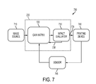
- FIG. 7 illustrates the structure and functions performed by a dynamic model predictive controller 700 , 200 of an image reproduction machine in accordance to an embodiment.
- a dynamic model predictive controller 700 , 200 would operate in accordance with pre-programmed instructions in a computer-readable media used to operate a local or networked computer system to carry out such features or perhaps on a plurality of interconnected computers at a time.
- a system might include a commercially available personal computer with computer-readable media and with appropriate graphics rendering capability that can also be associated with a networked storage medium or similar memory device wherein the system is accessible, perhaps via an Internet or intranet for submission of print jobs.
- one or more aspects of the system may be implemented on a dedicated computer workstation having a computer-readable media with appropriate instructions.
- FIG. 7 shows that the MPC 230 is connected to an image data source 710 , a printing device 740 , and a sensor 746 for sensing data related to print media count data, temperature data, component state data, print media timing data, imaging data, electrical parameters. These devices are coupled together via data or communication links 735 , 738 . These links may be any type of link that permits the transmission of data, such as direct serial connections, a local area network (LAN), wide area network (WAN), wireless network, an intranet, the Internet, circuit wirings, and the like.
- the content for a printing job is initially provided by the customer through an image data source 710 in a form acceptable to the system.
- the image data source 710 may be a personal computer, a microprocessor, a scanner, a disk drive, a tape drive, a hard disk, zip drive, CD-ROM drive, a DVD drive, a network server, a print server, a copying device, or any other known or later developed device or system that is able to provide the image data.
- Image data source 710 may include a plurality of components including displays, user interfaces, memory, disk drives, and the like.
- Printing device 740 may be any type of device that is capable of outputting a hard copy of an image and may take the form of a laser printer, a bubble jet printer, an ink jet printer, a copying machine, or any other known or later developed device or system that is able to generate an image on a recording medium using the image data or data generated from the image data.
- the model predictive controller (MPC) 230 employs gain matrix module 720 and impact evaluator 730 .
- the implementation of the MPC 230 selects a gain matrix which is selected from a set of gain matrices 720 within the iteration.
- the selection 738 is determined by impact evaluator 720 , which minimizes a predetermined performance function comparing the determined values to the measured or sensed values 745 for a control horizon.
- the best gain matrix is selected out of the minimization procedure which then becomes the gain matrix actively used during iteration.
- a receding horizon is implemented whereby at each time increment (t,t+T) the horizon is displaced one increment towards the future.
- FIG. 8 is a flowchart of method 800 in a process control system having a dynamic model predictive controller to provide control to an image reproduction machine in accordance to an embodiment.
- method 800 is started.
- the call may be encapsulated with values needed to initialize the DMPC algorithm, maximum number of iterations (imax), setting of all the parameters to be used during the implementation, and current iteration from other algorithms such as an Automated Spot Color Adjustment Editor (ASCE) algorithm when performing gloss variation or color variation.
- ASCE Automated Spot Color Adjustment Editor
- the parameters or group of parameters, such as prediction horizon, control horizon and weights for an image reproduction machine can be downloaded or uploaded onto the controller.
- disturbance preview data is acquired.
- sensing data is acquired.
- the acquired parameters 820 , disturbance preview 840 , and sensing data 850 are used to determine a horizon length.
- the horizon length relates to the maximum time to steady state considering all of the responses of the controlled variables for the changes in all of the manipulated variables plus the longest of the control horizon of all of the manipulated variables.
- the horizon length keeps being shifted forward (t+1) until the receding horizon reaches the total horizon length.
- a gain matrix is computed. It should be noted that multiple gain matrices can be determined for a MIMO state-feedback controller design using known method available in the art.
- updates to the gain matrix are received from other process or systems in the image reproduction machine.
- control is passed to method 900 for further processing.
- FIG. 9 is a flowchart outlining one exemplary embodiment of the operation of the dynamic model predictive controller over a defined horizon in accordance to an embodiment.
- a decision is made to determine if an index, i.e. (t+1), is less than the horizon length.
- the index represents the time increment for solving optimal control problem progressing towards the horizon length. If the index is less than the horizon length control passes to block 940 .
- a projection is determined over the defined horizon.
- the cost function is calculated over the defined horizon.
- the index is incremented by a desired amount (1, 2 . . . N). The actions are repeated until the index is greater than or equal to the horizon length.
- the cost function is determined.
- the cost function determined in block 920 is identical to the cost function determined in block 950 and could be passed by block 950 .
- the gain matrix is updated and forwarded to method 800 at node C to be used by block 860 .
Abstract
Description
(C,Cdyn=G(Mdyn,Ddyn)
Where G( ) describes dynamic response of the output variables as (C, Cdyn) to a given set of dynamic moves in Mdyn and dynamic disturbance future (disturbance preview) in Ddyn. (C, Cdyn) consist of steady state response (C) and dynamic response (Cdyn). It should be noted that the dynamic response should converge to the steady state response. The object of the dynamic model
Claims (20)
Priority Applications (2)
| Application Number | Priority Date | Filing Date | Title |
|---|---|---|---|
| US12/603,674 US8456674B2 (en) | 2009-10-22 | 2009-10-22 | Printing process model predictive control with disturbance preview |
| JP2010226315A JP5603729B2 (en) | 2009-10-22 | 2010-10-06 | Printing process model predictive control using disturbance preview |
Applications Claiming Priority (1)
| Application Number | Priority Date | Filing Date | Title |
|---|---|---|---|
| US12/603,674 US8456674B2 (en) | 2009-10-22 | 2009-10-22 | Printing process model predictive control with disturbance preview |
Publications (2)
| Publication Number | Publication Date |
|---|---|
| US20110096353A1 US20110096353A1 (en) | 2011-04-28 |
| US8456674B2 true US8456674B2 (en) | 2013-06-04 |
Family
ID=43898193
Family Applications (1)
| Application Number | Title | Priority Date | Filing Date |
|---|---|---|---|
| US12/603,674 Expired - Fee Related US8456674B2 (en) | 2009-10-22 | 2009-10-22 | Printing process model predictive control with disturbance preview |
Country Status (2)
| Country | Link |
|---|---|
| US (1) | US8456674B2 (en) |
| JP (1) | JP5603729B2 (en) |
Families Citing this family (3)
| Publication number | Priority date | Publication date | Assignee | Title |
|---|---|---|---|---|
| US8646893B2 (en) | 2012-06-19 | 2014-02-11 | Xerox Corporation | System and method for improving temperature uniformity of image drums |
| US10969749B2 (en) * | 2017-08-22 | 2021-04-06 | Honeywell Limited | Application of model predictive control (MPC)-based forced ramping of process input variables and process output reference trajectory design over a prediction horizon for MPC-based paper machine grade change control |
| JP6747409B2 (en) * | 2017-09-21 | 2020-08-26 | 京セラドキュメントソリューションズ株式会社 | Image forming apparatus and temperature control method |
Family Cites Families (1)
| Publication number | Priority date | Publication date | Assignee | Title |
|---|---|---|---|---|
| JP5119771B2 (en) * | 2007-07-09 | 2013-01-16 | 富士通株式会社 | Exchange apparatus, image forming apparatus, exchange program, exchange method |
-
2009
- 2009-10-22 US US12/603,674 patent/US8456674B2/en not_active Expired - Fee Related
-
2010
- 2010-10-06 JP JP2010226315A patent/JP5603729B2/en not_active Expired - Fee Related
Also Published As
| Publication number | Publication date |
|---|---|
| US20110096353A1 (en) | 2011-04-28 |
| JP5603729B2 (en) | 2014-10-08 |
| JP2011090300A (en) | 2011-05-06 |
Similar Documents
| Publication | Publication Date | Title |
|---|---|---|
| JP4116531B2 (en) | Image forming apparatus | |
| JP2010008805A (en) | Image forming apparatus, controller and program | |
| JP2009217163A (en) | Image forming apparatus and image forming method | |
| EP2775353B1 (en) | Electrophotographic image forming apparatus | |
| US8456674B2 (en) | Printing process model predictive control with disturbance preview | |
| US8369768B2 (en) | Cleaning blade parameter adjustment system | |
| US7463840B2 (en) | Electro-photographic image forming apparatus and method for determining a charging voltage | |
| US8005390B2 (en) | Optimization of reload performance for printer development systems with donor rolls | |
| US7356275B2 (en) | Apparatus and process for fuser control | |
| US8081891B2 (en) | Image quality adjustment method, image forming apparatus and computer readable medium | |
| US7218875B2 (en) | Apparatus and process for fuser control | |
| US7298980B2 (en) | Feed forward and feedback toner concentration control utilizing post transfer sensing for TC set point adjustment for an imaging system | |
| US20090080914A1 (en) | Image processing apparatus and image forming apparatus | |
| US20050214002A1 (en) | Apparatus and process for fuser control | |
| US7242884B2 (en) | Apparatus and process for fuser control | |
| JP2013195868A (en) | Image forming apparatus and image processing apparatus | |
| US20050214014A1 (en) | Apparatus and process for fuser control | |
| US9483004B2 (en) | Image forming apparatus for reducing fluctuation of toner density in a developing unit | |
| JP2013044790A (en) | Image forming apparatus | |
| JP2010145682A (en) | Image forming apparatus, image formation control method, and program executable on computer | |
| JP2018041057A (en) | Image forming apparatus | |
| JP2012220624A (en) | Image forming apparatus, image forming method, and program | |
| JP6443134B2 (en) | Paper posture adjusting device, fixing device, and image forming apparatus | |
| US8644743B2 (en) | Method and apparatus to improve belt roll fusing stripping latitude by strip shoe position adjustment | |
| JP5136337B2 (en) | Printing device |
Legal Events
| Date | Code | Title | Description |
|---|---|---|---|
| AS | Assignment |
Owner name: XEROX CORPORATION, CONNECTICUT Free format text: ASSIGNMENT OF ASSIGNORS INTEREST;ASSIGNORS:LI, FAMING;HAMBY, ERIC SCOTT;EUN, YONGSOON;REEL/FRAME:023407/0431 Effective date: 20091021 |
|
| FEPP | Fee payment procedure |
Free format text: PAYOR NUMBER ASSIGNED (ORIGINAL EVENT CODE: ASPN); ENTITY STATUS OF PATENT OWNER: LARGE ENTITY |
|
| STCF | Information on status: patent grant |
Free format text: PATENTED CASE |
|
| FPAY | Fee payment |
Year of fee payment: 4 |
|
| LAPS | Lapse for failure to pay maintenance fees |
Free format text: PATENT EXPIRED FOR FAILURE TO PAY MAINTENANCE FEES (ORIGINAL EVENT CODE: EXP.); ENTITY STATUS OF PATENT OWNER: LARGE ENTITY |
|
| FEPP | Fee payment procedure |
Free format text: MAINTENANCE FEE REMINDER MAILED (ORIGINAL EVENT CODE: REM.); ENTITY STATUS OF PATENT OWNER: LARGE ENTITY |
|
| STCH | Information on status: patent discontinuation |
Free format text: PATENT EXPIRED DUE TO NONPAYMENT OF MAINTENANCE FEES UNDER 37 CFR 1.362 |
|
| FP | Lapsed due to failure to pay maintenance fee |
Effective date: 20210604 |