US8437446B2 - Steam generator flow by-pass system - Google Patents
Steam generator flow by-pass system Download PDFInfo
- Publication number
- US8437446B2 US8437446B2 US12/272,175 US27217508A US8437446B2 US 8437446 B2 US8437446 B2 US 8437446B2 US 27217508 A US27217508 A US 27217508A US 8437446 B2 US8437446 B2 US 8437446B2
- Authority
- US
- United States
- Prior art keywords
- reactor
- coolant
- fluid
- reactor core
- primary
- Prior art date
- Legal status (The legal status is an assumption and is not a legal conclusion. Google has not performed a legal analysis and makes no representation as to the accuracy of the status listed.)
- Active, expires
Links
Images


Classifications
-
- G—PHYSICS
- G21—NUCLEAR PHYSICS; NUCLEAR ENGINEERING
- G21C—NUCLEAR REACTORS
- G21C1/00—Reactor types
- G21C1/32—Integral reactors, i.e. reactors wherein parts functionally associated with the reactor but not essential to the reaction, e.g. heat exchangers, are disposed inside the enclosure with the core
-
- G—PHYSICS
- G21—NUCLEAR PHYSICS; NUCLEAR ENGINEERING
- G21C—NUCLEAR REACTORS
- G21C15/00—Cooling arrangements within the pressure vessel containing the core; Selection of specific coolants
- G21C15/18—Emergency cooling arrangements; Removing shut-down heat
-
- G—PHYSICS
- G21—NUCLEAR PHYSICS; NUCLEAR ENGINEERING
- G21C—NUCLEAR REACTORS
- G21C1/00—Reactor types
- G21C1/32—Integral reactors, i.e. reactors wherein parts functionally associated with the reactor but not essential to the reaction, e.g. heat exchangers, are disposed inside the enclosure with the core
- G21C1/322—Integral reactors, i.e. reactors wherein parts functionally associated with the reactor but not essential to the reaction, e.g. heat exchangers, are disposed inside the enclosure with the core wherein the heat exchanger is disposed above the core
-
- G—PHYSICS
- G21—NUCLEAR PHYSICS; NUCLEAR ENGINEERING
- G21C—NUCLEAR REACTORS
- G21C15/00—Cooling arrangements within the pressure vessel containing the core; Selection of specific coolants
- G21C15/24—Promoting flow of the coolant
- G21C15/26—Promoting flow of the coolant by convection, e.g. using chimneys, using divergent channels
-
- Y—GENERAL TAGGING OF NEW TECHNOLOGICAL DEVELOPMENTS; GENERAL TAGGING OF CROSS-SECTIONAL TECHNOLOGIES SPANNING OVER SEVERAL SECTIONS OF THE IPC; TECHNICAL SUBJECTS COVERED BY FORMER USPC CROSS-REFERENCE ART COLLECTIONS [XRACs] AND DIGESTS
- Y02—TECHNOLOGIES OR APPLICATIONS FOR MITIGATION OR ADAPTATION AGAINST CLIMATE CHANGE
- Y02E—REDUCTION OF GREENHOUSE GAS [GHG] EMISSIONS, RELATED TO ENERGY GENERATION, TRANSMISSION OR DISTRIBUTION
- Y02E30/00—Energy generation of nuclear origin
- Y02E30/30—Nuclear fission reactors
Definitions
- the invention relates to a system for removing decay heat from a nuclear reactor.
- a nuclear reactor 5 includes a reactor core 6 surrounded by a reactor vessel 2 .
- Water 10 in the reactor vessel 2 surrounds the reactor core 6 .
- the reactor core 6 is further located in a shroud 122 which surround the reactor core 6 about its sides.
- the water 10 is heated by the reactor core 6 as a result of fission events, the water 10 is directed from the shroud 122 and out of a riser 124 . This results in further water 10 being drawn into and heated by the reactor core 6 which draws yet more water 10 into the shroud 122 .
- the water 10 that emerges from the riser 124 is cooled down and directed towards the annulus 123 and then returns to the bottom of the reactor vessel 2 through natural circulation. Pressurized steam 11 is produced in the reactor vessel 2 as the water 10 is heated.
- a heat exchanger 35 circulates feedwater and steam in a secondary cooling system 30 in order to generate electricity with a turbine 32 and generator 34 .
- the feedwater passes through the heat exchanger 35 and becomes super heated steam.
- the secondary cooling system 30 includes a condenser 36 and feedwater pump 38 .
- the steam and feedwater in the secondary cooling system 30 are isolated from the water 10 in the reactor vessel 2 , such that they are not allowed to mix or come into direct contact with each other.
- the reactor vessel 2 is surrounded by a containment vessel 4 .
- the containment vessel 4 is designed so that water or steam from the reactor vessel 2 is not allowed to escape into the surrounding environment.
- a steam valve 8 is provided to vent steam 11 from the reactor vessel 2 into an upper half 14 of the containment vessel 4 .
- a submerged blowdown valve 18 is provided to release the water 10 into suppression pool 12 containing sub-cooled water.
- the nuclear reactor 5 is designed to respond by scramming the reactor core 6 , flooding the containment vessel 4 or depressurizing the reactor vessel 2 .
- the latter two of these responses result in the nuclear reactor 5 being shut down and unable to generate electricity for an extended period of time.
- a flow of coolant through the reactor core 6 is reduced. This increases the time needed to bring the reactor core temperatures down to a desired level.
- the present invention addresses these and other problems.
- FIG. 1 illustrates a nuclear power system
- FIG. 2 illustrates a power module assembly comprising an internally dry containment vessel.
- FIG. 3 illustrates the power module assembly of FIG. 2 during an emergency operation.
- FIG. 4 illustrates an embodiment of a power module comprising a steam generator flow by-pass system during an emergency operation.
- FIG. 5 illustrates an embodiment of a power module comprising a steam generator flow by-pass system during normal operating conditions.
- FIG. 6A illustrates an embodiment of a steam generator flow by-pass system during normal operating conditions.
- FIG. 6B illustrates an embodiment of the steam generator flow by-pass system of FIG. 6A during a power-down operation.
- FIG. 7 illustrates an embodiment of a steam generator flow by-pass system comprising a through-passage.
- FIG. 8 illustrates an embodiment of a steam generator flow by-pass system comprising a valve.
- FIG. 9 illustrates an embodiment of a steam generator flow by-pass system comprising one or more baffles.
- FIG. 10 illustrates an embodiment of a steam generator flow by-pass system comprising a temperature activated passage.
- FIG. 11 illustrates an embodiment of a steam generator flow by-pass system comprising a ball check valve.
- FIG. 12 illustrates an embodiment of a steam generator flow by-pass system actuated by control rods.
- FIG. 13 illustrates an alternative embodiment of a steam generator flow by-pass system actuated by control rods
- FIG. 14 illustrates a novel method of cooling a reactor core using a steam generator flow by-pass system.
- a power module assembly is disclosed as comprising a reactor housing, a reactor core located in a lower portion of the reactor housing, and a heat exchanger proximately located about an upper portion of the reactor housing.
- the primary coolant flows out of the reactor housing via the upper portion, and the primary coolant flows into the reactor housing via the lower portion.
- the power module assembly further comprises a passageway provided in the reactor housing intermediate the lower portion and the upper portion, wherein the passageway is configured to provide an auxiliary flow of primary coolant to the reactor core to augment the flow of the primary coolant out of the upper portion of the reactor housing and into the lower portion.
- a nuclear reactor module is disclosed as comprising a reactor vessel and a reactor housing mounted inside the reactor vessel, wherein the reactor housing comprises a shroud and a riser located above the shroud.
- a heat exchanger is proximately located about the riser, and a reactor core is located in the shroud.
- the nuclear reactor module further comprises a steam generator by-pass system configured to provide an auxiliary flow path of primary coolant to the reactor core to augment a primary flow path of the primary coolant out of the riser and into the shroud, wherein the auxiliary flow path of primary coolant exits the reactor housing without passing by the heat exchanger.
- a method of cooling a nuclear reactor is disclosed.
- a primary coolant is circulated through a reactor housing comprising an upper riser and a lower shroud.
- a primary flow path of the primary coolant passes by a heat exchanger proximately located about the riser, and the primary coolant enters the lower shroud.
- a loss of coolant accident (LOCA) or a depressurization event is detected, and a fluid level of the primary coolant is decreased below the top of the riser.
- the primary flow path of primary coolant exits the riser as steam.
- An auxiliary flow path of primary coolant is circulated through an auxiliary passageway provided in the reactor housing, wherein the auxiliary flow path of primary coolant exits the reactor housing without passing by the heat exchanger.
- the primary coolant from the auxiliary flow path is combined with the primary coolant from the primary flow path that enters the lower shroud.
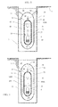
- FIG. 2 illustrates a power module assembly 50 comprising an internally dry containment vessel 54 .
- the containment vessel 54 is cylindrical in shape, and has spherical, domed, or ellipsoidal upper and lower ends.
- the entire power module assembly 50 may be submerged in a pool of water 16 which serves as an effective heat sink.
- the pool of water 16 and the containment vessel 54 may further be located below ground 9 in a reactor bay 7 .
- the containment vessel 54 may be welded or otherwise sealed to the environment, such that liquids and gas do not escape from, or enter, the power module assembly 50 .
- the containment vessel 54 may be supported at any external surface.
- the containment vessel 54 is suspended in the pool of water 16 by one or more mounting connections 80 .
- a reactor vessel 52 is located or mounted inside the containment vessel 54 .
- An inner surface of the reactor vessel 52 may be exposed to a wet environment including a coolant 100 or liquid, such as water, and an outer surface may be exposed to a dry environment such as air.
- the reactor vessel 52 may be made of stainless steel or carbon steel, may include cladding, and may be supported within the containment vessel 54 .
- the power module assembly 50 may be sized so that it can be transported on a rail car.
- the containment vessel 54 may be constructed to be approximately 4.3 meters in diameter and 17.7 meters in height (length). Refueling of the reactor core 6 may be performed by transporting the entire power module assembly 50 by rail car or overseas, for example, and replacing it with a new or refurbished power module assembly which has a fresh supply of fuel rods.
- the containment vessel 54 encapsulates and, in some conditions, cools the reactor core 6 . It is relatively small, has a high strength and may be capable of withstanding six or seven times the pressure of conventional containment designs in part due to its smaller overall dimensions. Given a break in the primary cooling system of the power module assembly 50 no fission products are released into the environment. Decay heat may be removed from the power module assembly 50 under emergency conditions.
- the reactor core 6 is illustrated as being submerged or immersed in a primary coolant 100 , such as water.
- the reactor vessel 52 houses the coolant 100 and the reactor core 6 .
- a reactor housing 20 comprises a shroud 22 in a lower portion and a riser 24 in an upper portion of the reactor housing 20 .
- the shroud 22 surrounds the reactor core 6 about its sides and serves to direct the coolant 100 (shown as coolant flow 65 , 67 ) up through the riser 24 located in the upper half of the reactor vessel 52 as a result of natural circulation of the coolant 100 .
- the reactor vessel 52 is approximately 2.7 meters in diameter and includes an overall height (length) of 13.7 meters.
- the reactor vessel 52 may include a predominately cylindrical shape with ellipsoidal, domed or spherical upper and lower ends.
- the reactor vessel 52 is normally at operating pressure and temperature.
- the containment vessel 54 is internally dry and may operate at atmospheric pressure with wall temperatures at or near the temperature of the pool of water 16 .
- the containment vessel 54 substantially surrounds the reactor vessel 52 and may provide a dry, voided, or gaseous environment identified as containment region 44 .
- Containment region 44 may comprise an amount of air or other fill gas such as Argonne or other nobel gas.
- the containment vessel 54 includes an inner surface 55 or inner wall which is adjacent to the containment region 44 .
- the containment region 44 may include a gas or gases instead of or in addition to air.
- the containment region 44 is maintained at or below atmospheric pressure, for example as a partial vacuum. Gas or gasses in the containment vessel may be removed such that the reactor vessel 52 is located in a complete or partial vacuum in the containment region 44 .
- coolant 100 During normal operation, thermal energy from the fission events in the reactor core 6 causes the coolant 100 to heat. As the coolant 100 heats up, it becomes less dense and tends to rise up through the riser 24 . As the coolant 100 temperature reduces, it becomes relatively denser than the heated coolant and is circulated around the outside of the annulus 23 , down to the bottom of the reactor vessel 52 and up through the shroud 22 to once again be heated by the reactor core 6 . This natural circulation causes the coolant 100 (shown as coolant flow 65 ) to cycle through the heat exchanger 35 , transferring heat to a secondary coolant, such as the secondary cooling system 30 of FIG. 1 to generate electricity.
- a secondary coolant such as the secondary cooling system 30 of FIG. 1
- FIG. 3 illustrates the power module assembly 50 of FIG. 2 during an emergency operation.
- the emergency operation may include a response to an overheating of the reactor core 6 , or an over-pressurization event of the reactor vessel 52 , for example.
- the reactor vessel 6 may be configured to release the coolant 100 into the containment region 44 of the otherwise dry containment vessel 54 .
- a decay heat of the reactor core 6 may be removed through condensation of the coolant 100 on the inner surface 55 of the containment vessel 54 .
- the containment vessel 54 may be immersed in a pool of water 16 , the inner surface 55 of the containment vessel 54 may be completely dry prior to the emergency operation or over-pressurization event.
- a flow limiter 58 or steam vent may be mounted on the reactor vessel 52 for venting the coolant 100 into the containment vessel 54 during the emergency operation.
- the coolant 100 may be released into the containment vessel 54 as vapor 41 , such as steam.
- the flow limiter 58 may be connected or mounted directly to an outer wall of the reactor vessel 52 , without any intervening structures such as piping or connections.
- the condensation of the vapor 41 may reduce pressure in the containment vessel 54 at approximately the same rate that the vented vapor 41 adds pressure to the containment vessel 54 .
- Coolant 100 that is released as vapor 41 into the containment vessel 54 condenses on the inner surface 55 of the containment vessel 54 as a liquid.
- the condensation of the vapor 41 causes the pressure in the containment vessel 54 to decrease, as the vapor 41 is transformed into the liquid coolant 100 .
- a sufficient amount of heat may be removed from the power module assembly 50 through the condensation of the vapor 41 on the inner surface 55 of the containment vessel to manage the removal of decay heat from the reactor core 6 .
- the condensed coolant 100 descends to the bottom of the containment vessel 54 and collects as a pool of liquid.
- Heat removed from the steam or vapor 41 may be transferred to the relatively cold inner surface 55 through condensation on the inside walls of the cold containment vessel 54 and by natural convection from the hot coolant to the inner surface 55 .
- Heat may be transferred to the pool of water 16 by conduction through the containment vessel walls and through natural convection on an outside surface of the containment vessel 54 .
- the coolant 100 remains confined within the power module assembly 50 after the reactor core 6 becomes over-heated and during the emergency operation.
- the heat transferred to the pool of water 16 may provide adequate passive decay heat removal for three or more days without any operator intervention.
- the containment vessel 54 may be designed to withstand the maximum pressure that would result given an instantaneous release of the high-pressure fluid from the reactor vessel 52 into the containment vessel 54 .
- the pressure inside the containment vessel 54 may be designed to approximately equilibrate with the pressure inside the reactor vessel 52 , reducing break flow caused by the pressure difference and resulting in coolant level 100 A in the reactor vessel 52 and coolant level 100 B in the containment vessel 54 as shown in FIG. 3 .
- the coolant level 100 B is shown elevated with respect to the coolant level 100 A due to an amount of hydrostatic driving force required for flow through the lower valves 57 back into the reactor vessel 52 .
- Differences in coolant levels 100 A and 100 B may also exist due to a pressure difference in the reactor vessel 52 relative to the containment vessel 54 due to the pressure drop of the steam flow valve 58 .
- FIG. 3 shows that the coolant levels 100 A and 100 B may equilibrate as a result of a hydrostatic head that is generated by in imbalance of the coolant levels. Coolant level 100 A in the reactor vessel 52 remains above the top of the reactor core 6 , keeping the reactor core 6 covered with coolant 100 at all times.
- the coolant level 100 A is maintained by steam or vapor being emitted from the riser 24 (shown as coolant flow 42 ) which condenses on the inner surface 55 of the reactor vessel 52 before collecting at the bottom of the reactor vessel 52 to be re-circulated through the reactor core 6 .
- a flow valve 57 may be provided to allow the coolant 100 to flow from the containment vessel 54 back into the reactor vessel 52 once an appropriate or predetermined condition of the coolant levels 100 A, 100 B is achieved. Coolant 100 that is allowed to reenter the reactor vessel 52 through the flow valve 57 replenishes the coolant 100 that was vented as vapor 41 through the flow limiter 58 .
- the flow of coolant 100 through the flow valve 57 may be achieved through the natural circulation of the passive system due to the different coolant densities and coolant levels that result from temperature differences and valve coolant flow in in the vessels 52 , 54 .
- a partial vacuum may be created in the containment vessel 54 .
- Any reference to a vacuum herein is therefore understood to be either a partial or complete vacuum.
- the containment region 44 is maintained at a vacuum pressure that significantly reduces convective and conductive heat transfer through the containment gases. By substantially removing gases from the containment region 44 , for example by maintaining a vacuum within the containment vessel 54 , an initial rate as well as subsequent rates of condensation of vapor 41 on the inner surface 55 are increased. Increasing the rate of condensation increases the rate of heat transfer through the containment vessel 54 .
- the introduced vapor or liquid provide a further passive safety cooling mechanism to transfer heat between the reactor vessel 52 and the containment vessel 54 through natural convection.
- a more effective heat transfer from the reactor vessel 52 can be made during an emergency operation due to the condensed liquid coolant 100 which pools at the bottom of the containment vessel 54 .
- Heat is transferred from the reactor vessel 52 through the liquid coolant 100 to the containment vessel 54 .
- FIG. 4 illustrates an embodiment of a power module assembly 40 comprising a steam generator flow by-pass system 45 during an emergency operation, such as a loss of coolant accident (LOCA) or an over-pressurization event.
- LOCA loss of coolant accident
- FIGS. 2-3 it should be understood that many or all of the features could be applied to the nuclear power system described with respect to FIG. 1 as well as conventional power systems.
- a reactor housing 20 is mounted inside the reactor vessel 52 , wherein the reactor housing 20 comprises the shroud 22 and the riser 24 located above the shroud 20 .
- the heat exchanger 35 is proximately located about the riser 24 .
- the reactor core 6 is located in the shroud 22 .
- the riser 24 is shown illustrated as being attached to the reactor vessel 52 by an upper attaching member 41
- the shroud is shown illustrated as being attached to the reactor vessel 52 by a lower attaching member 43 .
- the steam generator flow by-pass system 45 is configured to provide an auxiliary flow 48 of primary coolant to the reactor core 6 to augment a flow of the primary coolant 100 out of the riser 24 and into the shroud 22 .
- the auxiliary flow 48 of primary coolant exits the reactor housing 20 without passing by the heat exchanger 35 .
- the steam generator flow by-pass system 45 may provide a hydraulic connection through one or more components of the reactor housing 20 .
- the steam generator flow by-pass system 45 provides a hydraulic connection through the annulus (ref. 123 FIG. 1 ) located intermediate the riser 24 and the shroud 22 .
- the coolant flow 42 out of the upper portion (e.g. riser 24 ) of the reactor housing 20 comprises steam, wherein the auxiliary flow 48 of primary coolant comprises a mixture of two-phase coolant, such as boiling water.
- Coolant flow 42 exiting the riser 24 may comprise less coolant 100 by mass flow rate as compared to the coolant flow 67 ( FIG. 2 ) during normal operations (e.g. full power operation).
- Auxiliary flow 48 may therefore serve to make up some of the lost flow rate, such that the coolant flow 46 entering the shroud 22 is augmented to at or near the same flow rate as coolant flow 65 in FIG. 2 during normal operation.
- the coolant level 100 A is shown below the top of the riser 24 during the emergency operation.
- the reactor housing 20 is shown completely submerged in primary coolant 100 in FIG. 2
- the reactor housing 20 is only partially submerged in the coolant 100 as illustrated in FIG. 4 .
- the level of the primary coolant 100 remains above the passageway 45 during normal operation, as well as during an off-normal operation, shut-down or emergency operation, when steam generator by-pass occurs.
- the coolant flow 65 may be comprised of predominantly or exclusively single phase coolant, for example in a pressurized water reactor design (PWR). Accordingly, a flow of single phase coolant circulates through the reactor core 6 as coolant flow 65 and out the riser 24 as coolant flow 67 (see FIGS. 2 and 5 ). This provides for single-phase convection heat transfer at the surface of the fuel cladding in the reactor core 6 .
- PWR pressurized water reactor design
- the flow of single phase coolant may be interrupted.
- phase-change heat transfer may occur.
- Two-phase coolant may develop as it passes through the reactor core 6 which may then exit the reactor housing 20 via coolant flow 42 as steam which condenses on the inside wall of the reactor vessel 52 .
- auxiliary flow 48 By including the auxiliary flow 48 through the steam generator flow by-pass system 45 , convective heat transfer is provided to the reactor core 6 , in addition to the heat transfer that occurs through steam generation.
- the level of coolant 100 C within the riser 24 during the LOCA may drop down to a level that is approximately equal to that of the coolant level 100 A on the outside (downcomer) of the reactor housing 20 when the power module achieves a steady state condition.
- a steady state condition may occur when the coolant flow 46 entering the shroud 22 is equal to the combined flow rate of the coolant flow exiting the riser 24 and the auxiliary flow 48 exiting the steam generator flow by-pass system 45 .
- the steam generator flow by-pass system 45 is located above the reactor core 6 to optimize coolant flow through the fuel rods.
- the steam generator flow by-pass system 45 comprises a passageway provided in the reactor housing 20 intermediate the lower portion (e.g. shroud 22 ) and the upper portion (e.g. riser 24 ) of the housing 20 , wherein the passageway is configured to provide the auxiliary flow 48 of primary coolant to the reactor core 6 which augments the flow of the primary coolant 100 out of the upper portion of the reactor housing 20 and into the lower portion.
- the auxiliary flow 48 of primary coolant accordingly bypasses the heat exchanger 35 , located proximately about the upper portion of the reactor housing 20 .
- the passageway 45 may be closed during a full power operation of the power module assembly 40 , whereas during an emergency operating procedure, the passageway 45 is configured to open. Similarly, the passageway 45 may be configured to open during a shut-down, or power-down operation, including a LOCA or over-pressurization event. In one embodiment, the passageway remains open during all modes of operation, whereas the auxiliary flow 48 is substantially minimized or reduced to zero during normal operations of the power module assembly 40 .
- FIG. 5 illustrates an embodiment of a power module comprising a steam generator flow by-pass system 59 during normal operating conditions.
- the steam generator flow by-pass system 59 comprises an opening or passageway through the reactor housing 120 .
- the passageway may be located between or through a lower end 60 of the riser 24 and an upper end 62 of the shroud 22 .
- the coolant flow 65 passes through the reactor core 6 located in the shroud 22 before exiting the riser 24 as coolant flow 67 . During normal operations, little or none of the coolant flow 65 escapes through the steam generator flow by-pass system 59 .
- FIG. 6A illustrates an embodiment of a steam generator flow by-pass system 69 during normal operating conditions, such as when a power module is operating at full power.
- the power module generates an operating temperature that is typically higher than a temperature associated with reactor start-up, reactor shut-down, or other operating conditions. Different temperatures may be generated at different locations within the coolant 100 as a result of interaction with the heat exchanger 35 ( FIG. 4 ).
- coolant flow 65 and 67 behave substantially as described with respect to FIGS. 2 and 5 .
- Different components of the reactor housing 20 may undergo different amounts of thermal expansion, as a result of the difference in operating temperature or as a result of differences in thermal properties of the various components. For example, some components may be made out of different materials, composition, or amount (e.g. thickness), such that one component may expand or retract to a greater degree than another component.
- a direction of expansion or contraction of the shroud 22 and the riser 24 are in opposite directions.
- the shroud 22 expands toward the top of the reactor vessel 52 .
- This relationship is diagrammatically illustrated by the downward and upward facing arrows at the lower end 60 of the riser 24 and the upper end 62 of the shroud 22 , respectively.
- Expansion of the components in opposite directions may be accomplished by attaching the riser 24 to the upper attaching member 41 and by separately attaching the shroud 22 to the lower attaching member 43 ( FIG. 4 ).
- a passageway 63 in the upper end 62 of the shroud 22 is shown dislocated with a passageway 61 in the lower end 60 of the riser 24 .
- the dislocated passageways 61 , 63 do not line up, such that little or none of the coolant flow 65 is allowed to pass through the steam generator flow by-pass system 69 .
- FIG. 6B illustrates an embodiment of the steam generator flow by-pass system 69 of FIG. 6A during a power-down operation.
- the power down operation may include a reactor shut-down, reactor trip or SCRAM, LOCA, or overpressurization event, for example.
- temperatures in the reactor vessel 52 FIG. 2
- the shroud 22 retracts toward the bottom of the reactor vessel 52 .
- This relationship is diagrammatically illustrated by the upward and downward directed arrows at the lower end 60 of the riser 24 and the upper end 62 of the shroud 22 , respectively.
- the riser 24 and the shroud 22 may expand or contract at different amounts for the same change in temperature, in which case the directions of expansion and retraction may be relative to each other.
- the passageway 63 in the upper end 62 of the shroud 22 is shown aligned with the passageway 61 in the lower end 60 of the riser 24 , allowing an auxiliary flow 48 of coolant to pass through the steam generator flow by-pass system 69 .
- the co-located passageways 61 , 63 line-up to form a through-passage, such that the auxiliary flow 48 is combined with coolant flow 42 .
- the passageway 61 , 63 opens due to a change in temperature within the reactor vessel 52 ( FIG. 2 ), wherein a difference in rate of thermal expansion between the shroud 22 and the riser 24 causes the passageway 61 , 63 to open.
- a flow rate of the auxiliary flow 48 may vary according to the change in temperature, a degree of alignment between the passageways 61 , 63 , or the number of passageways provided in the reactor housing 20 .
- the auxiliary flow 48 of coolant exits the reactor housing 20 without passing by or through the heat exchanger 35 ( FIG. 4 ).
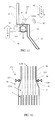
- FIG. 7 illustrates an embodiment of a steam generator flow by-pass system 79 comprising a through-passage 70 .
- the through-passage 70 may be formed between the lower end 60 of the riser 24 and the upper end 62 of the shroud 22 .
- the lower end 60 and upper end 62 are shown overlapping each other, such that the auxiliary flow 48 circulates through the through-passage 70 .
- FIG. 7 may be understood as representing the flow of coolant during a shut-down or power-down operation, in which coolant flow 42 provides a reduced flow rate as compared to coolant flow 67 of FIG. 5 .
- coolant flow 42 provides a reduced flow rate as compared to coolant flow 67 of FIG. 5 .
- coolant flows 65 , 67 may be sufficiently strong such that little or no auxiliary flow escapes from the steam generator flow by-pass system 59 .
- Flow paths through the riser 24 may provide the path of least resistance during normal operation.
- auxiliary flow 48 may be allowed to exit the through-passage 70 through natural convection, as coolant flow 46 exceeds the flow rate of coolant flow 42 .
- the primary coolant exits the steam generator flow by-pass system 79 as a result of a decrease in flow rate of the coolant flow 42 of the primary coolant out of the riser 24 .
- the decrease in flow rate may correspondingly decrease an amount of eddies that otherwise form in the through-passage 70 during normal operating conditions, allowing the coolant to “boil over” through the steam generator flow by-pass system 79 .
- the auxiliary flow 48 of primary coolant may exit the reactor housing 20 due to natural convection, or natural circulation of the coolant.
- a two-phase state of the coolant may promote auxiliary flow 48 of coolant to pass through the steam generator flow by-pass system, whereas most or all of the coolant would otherwise exit out the riser 24 when the coolant is in a single-phase state (e.g. during normal operating conditions).
- Passively cooling the reactor core 6 reduces or eliminates the need for providing moving or mechanical parts, such as motors.
- a distance between the overlapped section of the lower end 60 and upper end 62 increases or decreases with a change in temperature of the power module 40 .
- forces F 1 and F 2 may act on the ends 60 , 62 of the riser 24 and shroud 22 to increase the size of the through-passage 70 and provide for an increase in auxiliary flow 48 .
- the size of the through-passage 70 may decrease as the distance between the overlapped section of the ends 60 , 62 decreases, resulting in the auxiliary flow 48 decreasing or ceasing to flow.
- a flow rate of the auxiliary coolant 48 may vary with a change in reactor temperature and associated change in size or flow area of the through-passage 70 .
- FIG. 8 illustrates an embodiment of a steam generator flow by-pass system 89 comprising a valve 80 positioned near the lower end 60 of the riser 24 and the upper end 62 of the shroud 22 .
- Auxiliary flow 48 may be allowed to flow similarly as with regards to the description of FIG. 7 , whereas the valve 80 may be provided to limit a direction of the coolant flow 48 in a single direction.
- valve 80 is a unidirectional valve that limits the direction of coolant flow 48 from within the reactor housing 20 to outside of the reactor housing 20 .
- the valve 80 is always open, and the rate of auxiliary flow 48 is governed by the flow rate of coolant flow 42 , 46 or coolant flow 65 , 67 ( FIG. 5 ).
- valve 80 is actuated (e.g. opened) upon detection of a shut-down operation or reactor scram, for example, such that valve 80 is otherwise closed during normal (e.g. full power) reactor operation.
- FIG. 9 illustrates an embodiment of a steam generator flow by-pass system 99 comprising one or more baffles 90 .
- the auxiliary flow 48 through the baffles 90 may operate or function similarly as described above with respect to the embodiments illustrated in FIGS. 4-8 .
- little or no auxiliary flow 48 may be allowed to exit through the one or more baffles 90 .
- auxiliary flow 48 through the baffles 90 may be enabled or increased.
- the one or more baffles 90 rotate about a pivot to open or close.
- Baffle 90 A illustrates a baffle in a closed position
- baffle 90 B illustrates a baffle in an open position.
- the one or more baffles 90 may open or close depending on the flow rate of the coolant flow 42 , 46 , as these flow rates may exert pressure P 1 , P 2 on the one or more baffles 90 . If a flow rate or pressure differential between pressures P 1 , P 2 is great enough, the one or more baffles 90 may close, and prohibit a flow of coolant through the steam generator flow by-pass system 99 .
- the steam generator flow by-pass system 99 may further comprise a return mechanism, such as a spring, that returns the one or more baffles 90 to an open position when the flow rate drops below some predetermined threshold.
- a return mechanism such as a spring
- the steam generator flow by-pass system 99 comprises a screen with miniature louvers or baffles that allow the passage of boiling coolant, but prohibit or limit the passage of single phase coolant.
- FIG. 10 illustrates an embodiment of a steam generator flow by-pass system 109 comprising a temperature activated passage 100 .
- the passage 100 may be configured to open due to a change in temperature within the reactor vessel 52 ( FIG. 4 ).
- the steam generator flow by-pass system 109 comprises a bi-metallic cover located over the passageway, wherein the bi-metallic cover comprises materials having different thermal expansion rates or properties.
- the passageway is formed between the riser 24 and the shroud 22 .
- a first end of the temperature activated passage 100 may be fixed or otherwise attached to the reactor housing 20 ( FIG. 4 ). Due to the different thermal expansion properties, a second end of the temperature activated passage 100 may bend away from the reactor housing 20 with a force Fo as a reactor temperature decreases.
- a passageway through the reactor housing 20 may therefore be formed which allows the auxiliary flow 48 to exit the steam generator flow by-pass system 109 .
- the temperature activated passage 100 may relax, or bend back to cover the passageway (shown by reference 100 A) and reduce or stop the auxiliary flow 48 from exiting the reactor housing 20 .
- FIG. 11 illustrates an embodiment of a steam generator flow by-pass system 119 comprising a ball check valve 110 .
- the ball check valve 110 may move in a bi-direction sense, such that in one position it allows the auxiliary flow 48 to pass through the steam generator flow by-pass system 119 , whereas in a second position (e.g. shown as reference 110 A) it limits or prohibits the release of auxiliary flow 48 out of the reactor housing 20 .
- the steam generator flow by-pass system 119 may comprise a return spring 115 that urges the ball check valve 110 toward the open, first position.
- the amount of force exerted by the return spring 115 may exceed the force due to the coolant flow 48 during a shut-down condition, for example.
- a flow rate due to coolant flow 65 ( FIG. 5 ) may overcome the force exerted by the return spring 115 , and place the ball check valve 110 in the closed, second position 110 A.
- the weight of the ball in the ball check valve provides the downward force of the ball check valve 110 , replacing the need for the return spring 115 .
- a spring is located near the bottom of the ball check valve 110 , instead of as shown in FIG. 11 .
- the spring expands during normal operation due to an increase in temperature, urging the ball check valve 110 toward the closed, second position 110 A.
- the spring contracts during a power down condition due to a decrease in temperature, urging the ball check valve 110 toward the open, first position.
- FIG. 12 illustrates an embodiment of a steam generator flow by-pass system 129 actuated by control rods 125 A, 125 B.
- the steam generator flow by-pass system 129 may comprise one or more vents or valves 120 attached to the reactor housing 20 .
- the steam generator flow by-pass system 129 is attached to the reactor housing 20 intermediate the shroud 22 and the riser 24 .
- the steam generator flow by-pass system 129 may be actuated to be closed, such that little or no auxiliary flow is allowed to exit the reactor housing 20 .
- the steam generator flow by-pass system 129 may be closed, for example, during normal or full-power operation of the power module 40 .
- the steam generator flow by-pass system 129 may be actuated to be open, such that the auxiliary flow is allowed to exit the reactor housing 20 .
- the steam generator flow by-pass system 129 may be open, for example, during shut-down or a power down operation of the power module 40 .
- One or more switches or sensors may determine when the control rods 125 A, 125 B are inserted or removed from the reactor core 6 , and send a signal to actuate the steam generator flow by-pass system 129 .
- FIG. 13 illustrates an alternative embodiment of a steam generator flow by-pass system 139 actuated by control rods 135 A, 135 B.
- the steam generator flow by-pass system 139 may comprise one or more control rods designed such that when withdrawn ( 135 A) for operation they obstruct the flow path of the by-pass system, and when inserted ( 135 B) during power down conditions they provide an open passage to auxiliary coolant by-pass flow 48 .
- the location of the control rods 135 A, 135 B allow or prevent the auxiliary flow of primary coolant to pass through the housing 20 .
- the steam generator flow by-pass system 139 is attached to the reactor housing 20 intermediate the shroud 22 and the riser 24 .
- One or more switches or sensors may determine when the control rods are inserted ( 135 B) or removed ( 135 A) from the reactor core 6 .
- FIG. 14 illustrates a novel method of cooling a reactor core using a steam generator flow by-pass system. The method may be understood to operate with, but not limited by, various embodiments illustrated herein as FIGS. 1-13 .
- a primary coolant is circulated through a reactor housing comprising an upper riser and a lower shroud, wherein a primary flow path of the primary coolant passes by a heat exchanger proximately located about the riser, and wherein the primary coolant enters the lower shroud.
- LOCA loss of coolant accident
- depressurization event may indicate a reduced amount of coolant or pressure in the reactor vessel.
- a fluid level of the primary coolant is decreased below the top of the riser, wherein the primary coolant exits the riser as steam.
- the primary coolant that exits the riser as steam condenses as liquid coolant before being combined with an auxiliary flow path of the primary coolant that is circulated through an auxiliary passageway in the reactor housing.
- the auxiliary flow path of the primary coolant is circulated through the auxiliary passageway provided in the reactor housing, wherein the auxiliary flow path of the primary coolant exits the reactor housing without passing by the heat exchanger.
- the auxiliary flow path of the primary coolant circulates through the auxiliary passageway due to a difference in hydrostatic forces on either side of the passageway.
- the primary coolant from the auxiliary flow path is combined with the primary coolant from the primary flow path that enters the lower shroud.
- chemical additives soluble in coolant of a nuclear reactor are combined with the primary coolant of a nuclear reactor, modifying the nuclear and chemical characteristics of the coolant.
- a loss of primary coolant inventory is detected, and a fluid level of the primary coolant is decreased such that the nominal flow path is interrupted or reduced.
- Production of steam occurs in the core region, and exits the riser as steam.
- Non volatile additives in the primary coolant are concentrated in the core, and coolant devoid of the non-volatile additives collects in regions observing condensation.
- the primary coolant is circulated through a passageway provided in the reactor housing, wherein the coolant devoid of additives is combined with the coolant with increased concentration of additives, providing mixing of the coolant streams and mitigating the concentration process. Circulating the auxiliary flow path of the primary coolant through the auxiliary passageway reduces a concentration of non-volatile additives in the primary coolant within the reactor housing.
- the rate of release of the coolant into the containment vessel, the rate of condensation of the coolant into a liquid, and the rate of increase of pressure in the containment vessel, as well as other rates and values described herein are provided by way of example only. Other rates and values may be determined through experimentation such as by construction of full scale or scaled models of a nuclear reactor.
Landscapes
- Physics & Mathematics (AREA)
- Engineering & Computer Science (AREA)
- Plasma & Fusion (AREA)
- General Engineering & Computer Science (AREA)
- High Energy & Nuclear Physics (AREA)
- Chemical & Material Sciences (AREA)
- Chemical Kinetics & Catalysis (AREA)
- Structure Of Emergency Protection For Nuclear Reactors (AREA)
- Heat-Exchange Devices With Radiators And Conduit Assemblies (AREA)
Priority Applications (12)
| Application Number | Priority Date | Filing Date | Title |
|---|---|---|---|
| US12/272,175 US8437446B2 (en) | 2008-11-17 | 2008-11-17 | Steam generator flow by-pass system |
| CN201410455424.7A CN104299655B (zh) | 2008-11-17 | 2009-11-17 | 冷却核反应堆的方法 |
| CN200980153552.3A CN102272856B (zh) | 2008-11-17 | 2009-11-17 | 蒸汽发生器流动旁通系统 |
| CA2745703A CA2745703C (en) | 2008-11-17 | 2009-11-17 | Steam generator flow by-pass system |
| KR1020117013842A KR101313789B1 (ko) | 2008-11-17 | 2009-11-17 | 핵 반응로 및 핵 반응로의 냉각 방법 |
| PCT/US2009/064817 WO2010057193A1 (en) | 2008-11-17 | 2009-11-17 | Steam generator flow by-pass system |
| PL09760391T PL2366180T3 (pl) | 2008-11-17 | 2009-11-17 | Obejściowy system przepływu wytwornicy pary |
| ES09760391.4T ES2523958T3 (es) | 2008-11-17 | 2009-11-17 | Sistema de derivación de flujo de un generador de vapor |
| JP2011536599A JP5759899B2 (ja) | 2008-11-17 | 2009-11-17 | 発電モジュール組立体、原子炉モジュールおよび原子炉冷却方法 |
| EP09760391.4A EP2366180B1 (en) | 2008-11-17 | 2009-11-17 | Steam generator flow by-pass system |
| US13/860,750 US8824619B2 (en) | 2008-11-17 | 2013-04-11 | Steam generator flow by-pass system |
| HK15105056.3A HK1204707A1 (en) | 2008-11-17 | 2015-05-28 | Method of cooling a nuclear reactor |
Applications Claiming Priority (1)
| Application Number | Priority Date | Filing Date | Title |
|---|---|---|---|
| US12/272,175 US8437446B2 (en) | 2008-11-17 | 2008-11-17 | Steam generator flow by-pass system |
Related Child Applications (1)
| Application Number | Title | Priority Date | Filing Date |
|---|---|---|---|
| US13/860,750 Continuation US8824619B2 (en) | 2008-11-17 | 2013-04-11 | Steam generator flow by-pass system |
Publications (2)
| Publication Number | Publication Date |
|---|---|
| US20100124303A1 US20100124303A1 (en) | 2010-05-20 |
| US8437446B2 true US8437446B2 (en) | 2013-05-07 |
Family
ID=41650040
Family Applications (2)
| Application Number | Title | Priority Date | Filing Date |
|---|---|---|---|
| US12/272,175 Active 2030-02-20 US8437446B2 (en) | 2008-11-17 | 2008-11-17 | Steam generator flow by-pass system |
| US13/860,750 Active US8824619B2 (en) | 2008-11-17 | 2013-04-11 | Steam generator flow by-pass system |
Family Applications After (1)
| Application Number | Title | Priority Date | Filing Date |
|---|---|---|---|
| US13/860,750 Active US8824619B2 (en) | 2008-11-17 | 2013-04-11 | Steam generator flow by-pass system |
Country Status (10)
| Country | Link |
|---|---|
| US (2) | US8437446B2 (ja) |
| EP (1) | EP2366180B1 (ja) |
| JP (1) | JP5759899B2 (ja) |
| KR (1) | KR101313789B1 (ja) |
| CN (2) | CN104299655B (ja) |
| CA (1) | CA2745703C (ja) |
| ES (1) | ES2523958T3 (ja) |
| HK (1) | HK1204707A1 (ja) |
| PL (1) | PL2366180T3 (ja) |
| WO (1) | WO2010057193A1 (ja) |
Cited By (3)
| Publication number | Priority date | Publication date | Assignee | Title |
|---|---|---|---|---|
| US20100124303A1 (en) * | 2008-11-17 | 2010-05-20 | Nuscale Power, Inc. | Steam generator flow by-pass system |
| US10685756B2 (en) | 2017-11-10 | 2020-06-16 | Nugen, Llc | Integrated system for converting nuclear energy into electrical, rotational and thermal energy |
| US11421589B1 (en) | 2021-05-18 | 2022-08-23 | Nugen, Llc | Integrated system for converting nuclear energy into electrical, mechanical, and thermal energy |
Families Citing this family (25)
| Publication number | Priority date | Publication date | Assignee | Title |
|---|---|---|---|---|
| WO2011097597A1 (en) | 2010-02-05 | 2011-08-11 | Smr, Llc | Nuclear reactor system having natural circulation of primary coolant |
| US10535437B2 (en) * | 2010-02-18 | 2020-01-14 | Terrapower, Llc | Method, system, and apparatus for the thermal storage of nuclear reactor generated energy |
| CN102563590B (zh) * | 2010-12-22 | 2014-04-02 | 清华大学 | 一种饱和蒸汽发生器 |
| US8867689B2 (en) * | 2011-02-15 | 2014-10-21 | Nuscale Power, Llc | Heat removal system and method for use with a nuclear reactor |
| US20130044851A1 (en) * | 2011-08-17 | 2013-02-21 | Westinghouse Electric Company Llc | Backup nuclear reactor auxiliary power using decay heat |
| WO2013158762A1 (en) * | 2012-04-17 | 2013-10-24 | Babcock & Wilcox Mpower, Inc. | Integral vessel isolation valve |
| US9536629B2 (en) * | 2012-07-24 | 2017-01-03 | Westinghouse Electric Company Llc | Passive power production during a nuclear station blackout |
| WO2014113115A2 (en) * | 2012-10-25 | 2014-07-24 | Smr Inventec, Llc | Nuclear power generation system |
| US9738440B2 (en) * | 2012-12-20 | 2017-08-22 | Ge-Hitachi Nuclear Energy Americas Llc | Entrainment-reducing assembly, system including the assembly, and method of reducing entrainment of gases with the assembly |
| US9406409B2 (en) | 2013-03-06 | 2016-08-02 | Nuscale Power, Llc | Managing nuclear reactor spent fuel rods |
| WO2014200600A2 (en) | 2013-03-15 | 2014-12-18 | Babcock & Wilcox Mpower, Inc. | Passive techniques for long-term reactor cooling |
| JP6395802B2 (ja) * | 2013-03-15 | 2018-09-26 | ニュースケール パワー エルエルシー | 原子炉システムと方法 |
| KR101553888B1 (ko) | 2013-12-17 | 2015-09-17 | 한국원자력연구원 | 열교환기의 무전원 외부공기조절 자동댐핑장치 |
| US9997262B2 (en) | 2013-12-26 | 2018-06-12 | Nuscale Power, Llc | Integral reactor pressure vessel tube sheet |
| US10734123B2 (en) | 2014-04-18 | 2020-08-04 | Agenzia Nazionale Per Le Nuove Tecnologie, L'energia E Lo Sviluppo Economico Sostenible (Enea) | Passive system for evacuating the residual heat from a nuclear reactor |
| US10629312B2 (en) | 2014-12-23 | 2020-04-21 | Nuscale Power, Llc | Light water reactor with condensing steam generator |
| CN105810256B (zh) * | 2014-12-29 | 2019-02-22 | 国核华清(北京)核电技术研发中心有限公司 | 一种核电站非能动余热排出系统 |
| US10685752B2 (en) | 2015-02-10 | 2020-06-16 | Nuscale Power, Llc | Steam generator with inclined tube sheet |
| JP6705832B2 (ja) | 2015-03-19 | 2020-06-03 | ハイドロミン ニュクレアル エネルジー ソシエテ ア レスポンサビリテ リミティー | 原子炉 |
| KR101654096B1 (ko) | 2015-04-17 | 2016-09-07 | 한국원자력연구원 | 자가진단 사고대처 무인 원자로 |
| US11380451B2 (en) * | 2017-08-15 | 2022-07-05 | Ge-Hitachi Nuclear Energy Americas Llc | Depressurization and coolant injection systems for very simplified boiling water reactors |
| US10937557B2 (en) * | 2017-10-17 | 2021-03-02 | Ge-Hitachi Nuclear Energy Americas Llc | Systems and methods for airflow control in reactor passive decay heat removal |
| CN112071451B (zh) * | 2020-09-15 | 2022-11-01 | 哈尔滨工程大学 | 一种压水堆多功能双层混凝土安全壳系统 |
| FI129308B (en) | 2020-11-20 | 2021-11-30 | Teknologian Tutkimuskeskus Vtt Oy | Nuclear reactor module and a nuclear nuclear thermal reactor comprising the same and a method for operating the nuclear reactor module |
| KR102631576B1 (ko) * | 2021-07-21 | 2024-02-02 | 한국원자력연구원 | 키르히호프 법칙에 기반한 우회유로관을 가지는 원자로 |
Citations (16)
| Publication number | Priority date | Publication date | Assignee | Title |
|---|---|---|---|---|
| FR1445877A (fr) | 1964-08-18 | 1966-07-15 | Anglo Belge Vulcain Soc | Perfectionnements aux réacteurs nucléaires |
| US3401082A (en) * | 1966-05-24 | 1968-09-10 | Babcock & Wilcox Co | Integral steam generator and nuclear reactor combination |
| US3599589A (en) | 1967-12-29 | 1971-08-17 | Mc Donnell Douglas Corp | Earthquake-resistant nuclear reactor station |
| US3865688A (en) | 1970-08-05 | 1975-02-11 | Frank W Kleimola | Passive containment system |
| US4554129A (en) * | 1982-03-17 | 1985-11-19 | The United States Of America As Represented By The United States Department Of Energy | Gas-cooled nuclear reactor |
| US4725400A (en) * | 1984-12-18 | 1988-02-16 | Hochtemperatur-Reaktorbau Gmbh | Nuclear reactor plant housed in a steel pressure vessel, with a gas cooled, small high temperature reactor |
| US4793964A (en) * | 1986-05-22 | 1988-12-27 | Commissariat A L'energie Atomique | Small natural circulation pressurized water nuclear reactor |
| US5053190A (en) * | 1988-04-13 | 1991-10-01 | Rolls-Royce And Associates Limited | Water cooled nuclear reactor and pressurizer assembly |
| US5087408A (en) | 1987-03-18 | 1992-02-11 | Kenji Tominaga | Nuclear power facilities |
| US5102616A (en) * | 1988-07-21 | 1992-04-07 | Rolls-Royce And Associates Limited | Full pressure passive emergency core cooling and residual heat removal system for water cooled nuclear reactors |
| EP0518593A1 (en) | 1991-06-13 | 1992-12-16 | General Electric Company | Forced-circulation reactor with enhanced flow in natural circulation operation |
| US5276720A (en) | 1992-11-02 | 1994-01-04 | General Electric Company | Emergency cooling system and method |
| JPH0666983A (ja) | 1992-06-05 | 1994-03-11 | General Electric Co <Ge> | 自然循環用流体ダイオードを有する強制循環原子炉 |
| US5349617A (en) * | 1992-04-28 | 1994-09-20 | Commissariat A L'energie Atomique | Apparatus for removing the residual power of a pressurized nuclear reactor core |
| US6795518B1 (en) | 2001-03-09 | 2004-09-21 | Westinghouse Electric Company Llc | Integral PWR with diverse emergency cooling and method of operating same |
| US20060146975A1 (en) * | 2004-12-09 | 2006-07-06 | Kabushiki Kaisha Toshiba | Nuclear power plant, method of forming corrosion-resistant coating therefor, and method of operating nuclear power plant |
Family Cites Families (11)
| Publication number | Priority date | Publication date | Assignee | Title |
|---|---|---|---|---|
| US3856688A (en) | 1972-07-25 | 1974-12-24 | Us Agriculture | Ether-containing dibasic fatty acid metal soap thickened greases |
| DE2455508C2 (de) * | 1974-11-23 | 1982-06-24 | Hochtemperatur-Reaktorbau GmbH, 5000 Köln | Vorrichtung zum Erzeugen von Synthesegas durch Ausnutzen der in einem gasgekühlten Hochtemperaturreaktor gewonnenen Wärmeenergie |
| JPH02311794A (ja) * | 1989-05-26 | 1990-12-27 | Ishikawajima Harima Heavy Ind Co Ltd | 原子炉の非常時制御装置 |
| US5089216A (en) * | 1990-11-26 | 1992-02-18 | Westinghouse Electric Corp. | System for chemical decontamination of nuclear reactor primary systems |
| US5217682A (en) * | 1991-05-17 | 1993-06-08 | Atomic Energy Of Canada Limited | Passive indirect shutdown cooling system for nuclear reactors |
| US5309487A (en) * | 1992-06-24 | 1994-05-03 | Westinghouse Electric Corp. | Mitigation of steam generator tube rupture in a pressurized water reactor with passive safety systems |
| JPH07134193A (ja) * | 1993-11-12 | 1995-05-23 | Toshiba Eng Co Ltd | ドライウェルの冷却装置 |
| JP2002156485A (ja) * | 2000-11-15 | 2002-05-31 | Hitachi Ltd | 原子炉 |
| FR2832846B1 (fr) * | 2001-11-26 | 2005-12-09 | Commissariat Energie Atomique | Reacteur nucleaire compact a eau sous pression |
| JP2004012145A (ja) * | 2002-06-03 | 2004-01-15 | Toshiba Corp | 非凝縮性ガスの蓄積燃焼防止システム |
| US8437446B2 (en) * | 2008-11-17 | 2013-05-07 | Nuscale Power, Llc | Steam generator flow by-pass system |
-
2008
- 2008-11-17 US US12/272,175 patent/US8437446B2/en active Active
-
2009
- 2009-11-17 ES ES09760391.4T patent/ES2523958T3/es active Active
- 2009-11-17 WO PCT/US2009/064817 patent/WO2010057193A1/en active Application Filing
- 2009-11-17 CN CN201410455424.7A patent/CN104299655B/zh active Active
- 2009-11-17 CN CN200980153552.3A patent/CN102272856B/zh active Active
- 2009-11-17 EP EP09760391.4A patent/EP2366180B1/en active Active
- 2009-11-17 JP JP2011536599A patent/JP5759899B2/ja active Active
- 2009-11-17 KR KR1020117013842A patent/KR101313789B1/ko active IP Right Grant
- 2009-11-17 PL PL09760391T patent/PL2366180T3/pl unknown
- 2009-11-17 CA CA2745703A patent/CA2745703C/en active Active
-
2013
- 2013-04-11 US US13/860,750 patent/US8824619B2/en active Active
-
2015
- 2015-05-28 HK HK15105056.3A patent/HK1204707A1/xx unknown
Patent Citations (16)
| Publication number | Priority date | Publication date | Assignee | Title |
|---|---|---|---|---|
| FR1445877A (fr) | 1964-08-18 | 1966-07-15 | Anglo Belge Vulcain Soc | Perfectionnements aux réacteurs nucléaires |
| US3401082A (en) * | 1966-05-24 | 1968-09-10 | Babcock & Wilcox Co | Integral steam generator and nuclear reactor combination |
| US3599589A (en) | 1967-12-29 | 1971-08-17 | Mc Donnell Douglas Corp | Earthquake-resistant nuclear reactor station |
| US3865688A (en) | 1970-08-05 | 1975-02-11 | Frank W Kleimola | Passive containment system |
| US4554129A (en) * | 1982-03-17 | 1985-11-19 | The United States Of America As Represented By The United States Department Of Energy | Gas-cooled nuclear reactor |
| US4725400A (en) * | 1984-12-18 | 1988-02-16 | Hochtemperatur-Reaktorbau Gmbh | Nuclear reactor plant housed in a steel pressure vessel, with a gas cooled, small high temperature reactor |
| US4793964A (en) * | 1986-05-22 | 1988-12-27 | Commissariat A L'energie Atomique | Small natural circulation pressurized water nuclear reactor |
| US5087408A (en) | 1987-03-18 | 1992-02-11 | Kenji Tominaga | Nuclear power facilities |
| US5053190A (en) * | 1988-04-13 | 1991-10-01 | Rolls-Royce And Associates Limited | Water cooled nuclear reactor and pressurizer assembly |
| US5102616A (en) * | 1988-07-21 | 1992-04-07 | Rolls-Royce And Associates Limited | Full pressure passive emergency core cooling and residual heat removal system for water cooled nuclear reactors |
| EP0518593A1 (en) | 1991-06-13 | 1992-12-16 | General Electric Company | Forced-circulation reactor with enhanced flow in natural circulation operation |
| US5349617A (en) * | 1992-04-28 | 1994-09-20 | Commissariat A L'energie Atomique | Apparatus for removing the residual power of a pressurized nuclear reactor core |
| JPH0666983A (ja) | 1992-06-05 | 1994-03-11 | General Electric Co <Ge> | 自然循環用流体ダイオードを有する強制循環原子炉 |
| US5276720A (en) | 1992-11-02 | 1994-01-04 | General Electric Company | Emergency cooling system and method |
| US6795518B1 (en) | 2001-03-09 | 2004-09-21 | Westinghouse Electric Company Llc | Integral PWR with diverse emergency cooling and method of operating same |
| US20060146975A1 (en) * | 2004-12-09 | 2006-07-06 | Kabushiki Kaisha Toshiba | Nuclear power plant, method of forming corrosion-resistant coating therefor, and method of operating nuclear power plant |
Non-Patent Citations (7)
| Title |
|---|
| Dr. Jose N. Reyes, Jr., "NuScale Power Introduction to NuScale Design" U.S. Nuclear Regulatory Commission Pre-Application Meeting, Rockville, MD, Jul. 24, 2008 (26 pages). |
| European Patent Office, "International Search Report" for International Application No. PCT/US2009/064817, Feb. 25, 2010. |
| Foreign office action Article 94(3) EPC for Application No. 09760391.4-2208, dated Apr. 3, 2012, 7 pages. |
| IAEA; IAEA Tecdoc 1391-Status of Advanced Light Water Reactor Designs 2004; May 2004; pp. 279-306, 489-512; Nuclear Power Technology Development Section, International Atomic Energy Agency; Vienna; Austria. |
| IAEA; IAEA Tecdoc 1485-Status of Innovative Small and Medium Sized Reactor Designs 2005; Mar. 2006; pp. 93-162; Nuclear Power Technology Development Section, International Atomic Energy Agency; Vienna; Austria. |
| Modro, S.M., et al.; 'Multi-Application Small Light Water Reactor Final Report; Idaho National Engineering and Environmental Laboratory; Dec. 2003; Idaho Falls, ID, U.S.A. |
| Reyes et al.; "Testing of the multi-application small light water reactor (MASLWR) passive safety systems" Nuclear Engineering and Design, Amsterdam, NL, vol. 237 No. 18, Aug. 25, 2007. |
Cited By (9)
| Publication number | Priority date | Publication date | Assignee | Title |
|---|---|---|---|---|
| US20100124303A1 (en) * | 2008-11-17 | 2010-05-20 | Nuscale Power, Inc. | Steam generator flow by-pass system |
| US8824619B2 (en) * | 2008-11-17 | 2014-09-02 | NuScale Powe, LLC | Steam generator flow by-pass system |
| US10685756B2 (en) | 2017-11-10 | 2020-06-16 | Nugen, Llc | Integrated system for converting nuclear energy into electrical, rotational and thermal energy |
| US10685755B2 (en) | 2017-11-10 | 2020-06-16 | Nugen, Llc | Integrated system for converting nuclear energy into electrical, rotational, and thermal energy |
| US10755826B2 (en) | 2017-11-10 | 2020-08-25 | Nugen, Llc | Integrated system for converting nuclear energy into electrical, rotational, and thermal energy |
| US10784006B2 (en) | 2017-11-10 | 2020-09-22 | Nugen, Llc | Integrated system for converting nuclear energy into rotational and thermal energy |
| US11482346B2 (en) | 2017-11-10 | 2022-10-25 | Nugen, Llc | Integrated system for converting nuclear energy into electrical, mechanical, and thermal energy |
| US11421589B1 (en) | 2021-05-18 | 2022-08-23 | Nugen, Llc | Integrated system for converting nuclear energy into electrical, mechanical, and thermal energy |
| US11815013B2 (en) | 2021-05-18 | 2023-11-14 | Nugen, Llc | Integrated system for converting nuclear energy into electrical, mechanical, and thermal energy |
Also Published As
| Publication number | Publication date |
|---|---|
| CN102272856A (zh) | 2011-12-07 |
| CA2745703A1 (en) | 2010-05-20 |
| JP2012509465A (ja) | 2012-04-19 |
| ES2523958T3 (es) | 2014-12-03 |
| WO2010057193A1 (en) | 2010-05-20 |
| PL2366180T3 (pl) | 2015-03-31 |
| EP2366180A1 (en) | 2011-09-21 |
| CN104299655B (zh) | 2017-05-24 |
| US8824619B2 (en) | 2014-09-02 |
| CN104299655A (zh) | 2015-01-21 |
| KR101313789B1 (ko) | 2013-09-30 |
| HK1204707A1 (en) | 2015-11-27 |
| KR20110106852A (ko) | 2011-09-29 |
| JP5759899B2 (ja) | 2015-08-05 |
| EP2366180B1 (en) | 2014-09-03 |
| US20100124303A1 (en) | 2010-05-20 |
| CA2745703C (en) | 2016-03-22 |
| CN102272856B (zh) | 2014-10-01 |
| US20130266111A1 (en) | 2013-10-10 |
Similar Documents
| Publication | Publication Date | Title |
|---|---|---|
| US8437446B2 (en) | Steam generator flow by-pass system | |
| KR101215323B1 (ko) | 원자로를 포함하는 원자로 조립체, 원자로용 비상 냉각 시스템, 및 원자로의 비상 냉각 방법 | |
| US11756698B2 (en) | Passive emergency feedwater system | |
| EP2862176B1 (en) | Small modular reactor safety systems | |
| EP3369096B1 (en) | Passive cooling to cold shutdown | |
| CA2745573C (en) | Reactor vessel coolant deflector shield | |
| EP3005373B1 (en) | Passive reactor cooling system | |
| JP2014513280A (ja) | 加圧水型原子炉用のエネルギー炉心冷却系統 | |
| EP3087566B1 (en) | Integral reactor pressure vessel tube sheet | |
| US10720249B2 (en) | Passive reactor cooling system | |
| US9583221B2 (en) | Integrated emergency core cooling system condenser for pressurized water reactor | |
| KR101250479B1 (ko) | 안전보호용기를 구비한 피동형 비상노심냉각설비 및 이를 이용한 열 전달량 증가 방법 | |
| JP2016507758A (ja) | 加圧水型原子炉の減圧システム | |
| KR101513163B1 (ko) | 역압 안전 밸브를 갖는 자기 냉각 피동 원자로 |
Legal Events
| Date | Code | Title | Description |
|---|---|---|---|
| AS | Assignment |
Owner name: NUSCALE POWER, INC.,OREGON Free format text: ASSIGNMENT OF ASSIGNORS INTEREST;ASSIGNORS:YOUNG, ERIC PAUL;GROOME, JOHN T.;REYES, JOSE N., JR;REEL/FRAME:021844/0676 Effective date: 20081114 Owner name: NUSCALE POWER, INC., OREGON Free format text: ASSIGNMENT OF ASSIGNORS INTEREST;ASSIGNORS:YOUNG, ERIC PAUL;GROOME, JOHN T.;REYES, JOSE N., JR;REEL/FRAME:021844/0676 Effective date: 20081114 |
|
| AS | Assignment |
Owner name: MICHAEL KENWOOD ASSET MANAGEMENT, LLC,CONNECTICUT Free format text: SECURITY AGREEMENT;ASSIGNOR:NUSCALE POWER, INC.;REEL/FRAME:023071/0641 Effective date: 20090727 Owner name: MICHAEL KENWOOD ASSET MANAGEMENT, LLC, CONNECTICUT Free format text: SECURITY AGREEMENT;ASSIGNOR:NUSCALE POWER, INC.;REEL/FRAME:023071/0641 Effective date: 20090727 |
|
| AS | Assignment |
Owner name: NUSCALE POWER, INC.,OREGON Free format text: RELEASE BY SECURED PARTY;ASSIGNOR:MICHAEL KENWOOD ASSET MANAGEMENT, LLC;REEL/FRAME:023393/0252 Effective date: 20091019 Owner name: NUSCALE POWER, INC., OREGON Free format text: RELEASE BY SECURED PARTY;ASSIGNOR:MICHAEL KENWOOD ASSET MANAGEMENT, LLC;REEL/FRAME:023393/0252 Effective date: 20091019 |
|
| AS | Assignment |
Owner name: MICHAEL KENWOOD ASSET MANAGEMENT, LLC,CONNECTICUT Free format text: SECURITY AGREEMENT;ASSIGNOR:NUSCALE POWER, INC.;REEL/FRAME:023874/0802 Effective date: 20100119 Owner name: GREEN ENERGY METALS ACQUISITION FUND, LP,OREGON Free format text: SECURITY AGREEMENT;ASSIGNOR:NUSCALE POWER, INC.;REEL/FRAME:023874/0802 Effective date: 20100119 Owner name: GRAHAM, DOUG,OREGON Free format text: SECURITY AGREEMENT;ASSIGNOR:NUSCALE POWER, INC.;REEL/FRAME:023874/0802 Effective date: 20100119 Owner name: CMEA VENTURES VII (PARALLEL), L.P.,CALIFORNIA Free format text: SECURITY AGREEMENT;ASSIGNOR:NUSCALE POWER, INC.;REEL/FRAME:023874/0802 Effective date: 20100119 Owner name: CMEA VENTURES VII, L.P.,CALIFORNIA Free format text: SECURITY AGREEMENT;ASSIGNOR:NUSCALE POWER, INC.;REEL/FRAME:023874/0802 Effective date: 20100119 Owner name: CMEA VENTURES VII (PARALLEL), L.P., CALIFORNIA Free format text: SECURITY AGREEMENT;ASSIGNOR:NUSCALE POWER, INC.;REEL/FRAME:023874/0802 Effective date: 20100119 Owner name: MICHAEL KENWOOD ASSET MANAGEMENT, LLC, CONNECTICUT Free format text: SECURITY AGREEMENT;ASSIGNOR:NUSCALE POWER, INC.;REEL/FRAME:023874/0802 Effective date: 20100119 Owner name: CMEA VENTURES VII, L.P., CALIFORNIA Free format text: SECURITY AGREEMENT;ASSIGNOR:NUSCALE POWER, INC.;REEL/FRAME:023874/0802 Effective date: 20100119 Owner name: GREEN ENERGY METALS ACQUISITION FUND, LP, OREGON Free format text: SECURITY AGREEMENT;ASSIGNOR:NUSCALE POWER, INC.;REEL/FRAME:023874/0802 Effective date: 20100119 Owner name: GRAHAM, DOUG, OREGON Free format text: SECURITY AGREEMENT;ASSIGNOR:NUSCALE POWER, INC.;REEL/FRAME:023874/0802 Effective date: 20100119 |
|
| AS | Assignment |
Owner name: NUSCALE POWER, INC., OREGON Free format text: RELEASE BY SECURED PARTY;ASSIGNORS:CMEA VENTURES VII, L.P.;CMEA VENTURES VII (PARALLEL), L.P.;GREEN ENERGY METALS ACQUISITION FUND, LP;AND OTHERS;REEL/FRAME:027097/0702 Effective date: 20100830 Owner name: FLUOR ENTERPRISES, INC., TEXAS Free format text: ASSIGNMENT OF SECURITY INTEREST;ASSIGNOR:MICHAEL KENWOOD ASSET MANAGEMENT, LLC;REEL/FRAME:027097/0753 Effective date: 20110930 |
|
| AS | Assignment |
Owner name: NUSCALE POWER, LLC, OREGON Free format text: CHANGE OF NAME;ASSIGNOR:NUSCALE POWER, INC.;REEL/FRAME:027172/0370 Effective date: 20110930 |
|
| AS | Assignment |
Owner name: NUSCALE POWER, INC., OREGON Free format text: ASSIGNMENT OF ASSIGNORS INTEREST;ASSIGNORS:YOUNG, ERIC PAUL;GROOME, JOHN T.;REYES, JOSE N., JR.;REEL/FRAME:027191/0411 Effective date: 20081114 |
|
| STCF | Information on status: patent grant |
Free format text: PATENTED CASE |
|
| FPAY | Fee payment |
Year of fee payment: 4 |
|
| MAFP | Maintenance fee payment |
Free format text: PAYMENT OF MAINTENANCE FEE, 8TH YEAR, LARGE ENTITY (ORIGINAL EVENT CODE: M1552); ENTITY STATUS OF PATENT OWNER: LARGE ENTITY Year of fee payment: 8 |