US8427042B2 - Light-emitting device and method for manufacturing light-emitting device - Google Patents
Light-emitting device and method for manufacturing light-emitting device Download PDFInfo
- Publication number
- US8427042B2 US8427042B2 US12/502,691 US50269109A US8427042B2 US 8427042 B2 US8427042 B2 US 8427042B2 US 50269109 A US50269109 A US 50269109A US 8427042 B2 US8427042 B2 US 8427042B2
- Authority
- US
- United States
- Prior art keywords
- phosphor
- light
- kneaded matter
- emitting device
- resin
- Prior art date
- Legal status (The legal status is an assumption and is not a legal conclusion. Google has not performed a legal analysis and makes no representation as to the accuracy of the status listed.)
- Expired - Fee Related, expires
Links
Images


Classifications
-
- H—ELECTRICITY
- H05—ELECTRIC TECHNIQUES NOT OTHERWISE PROVIDED FOR
- H05B—ELECTRIC HEATING; ELECTRIC LIGHT SOURCES NOT OTHERWISE PROVIDED FOR; CIRCUIT ARRANGEMENTS FOR ELECTRIC LIGHT SOURCES, IN GENERAL
- H05B33/00—Electroluminescent light sources
- H05B33/12—Light sources with substantially two-dimensional [2D] radiating surfaces
- H05B33/14—Light sources with substantially two-dimensional [2D] radiating surfaces characterised by the chemical or physical composition or the arrangement of the electroluminescent material, or by the simultaneous addition of the electroluminescent material in or onto the light source
- H05B33/145—Arrangements of the electroluminescent material
-
- H—ELECTRICITY
- H10—SEMICONDUCTOR DEVICES; ELECTRIC SOLID-STATE DEVICES NOT OTHERWISE PROVIDED FOR
- H10H—INORGANIC LIGHT-EMITTING SEMICONDUCTOR DEVICES HAVING POTENTIAL BARRIERS
- H10H20/00—Individual inorganic light-emitting semiconductor devices having potential barriers, e.g. light-emitting diodes [LED]
- H10H20/80—Constructional details
- H10H20/85—Packages
- H10H20/851—Wavelength conversion means
- H10H20/8511—Wavelength conversion means characterised by their material, e.g. binder
- H10H20/8512—Wavelength conversion materials
- H10H20/8513—Wavelength conversion materials having two or more wavelength conversion materials
-
- H—ELECTRICITY
- H10—SEMICONDUCTOR DEVICES; ELECTRIC SOLID-STATE DEVICES NOT OTHERWISE PROVIDED FOR
- H10H—INORGANIC LIGHT-EMITTING SEMICONDUCTOR DEVICES HAVING POTENTIAL BARRIERS
- H10H20/00—Individual inorganic light-emitting semiconductor devices having potential barriers, e.g. light-emitting diodes [LED]
- H10H20/80—Constructional details
- H10H20/85—Packages
- H10H20/852—Encapsulations
- H10H20/853—Encapsulations characterised by their shape
-
- H—ELECTRICITY
- H10—SEMICONDUCTOR DEVICES; ELECTRIC SOLID-STATE DEVICES NOT OTHERWISE PROVIDED FOR
- H10W—GENERIC PACKAGES, INTERCONNECTIONS, CONNECTORS OR OTHER CONSTRUCTIONAL DETAILS OF DEVICES COVERED BY CLASS H10
- H10W72/00—Interconnections or connectors in packages
- H10W72/50—Bond wires
- H10W72/531—Shapes of wire connectors
- H10W72/536—Shapes of wire connectors the connected ends being ball-shaped
-
- H—ELECTRICITY
- H10—SEMICONDUCTOR DEVICES; ELECTRIC SOLID-STATE DEVICES NOT OTHERWISE PROVIDED FOR
- H10W—GENERIC PACKAGES, INTERCONNECTIONS, CONNECTORS OR OTHER CONSTRUCTIONAL DETAILS OF DEVICES COVERED BY CLASS H10
- H10W72/00—Interconnections or connectors in packages
- H10W72/50—Bond wires
- H10W72/531—Shapes of wire connectors
- H10W72/5363—Shapes of wire connectors the connected ends being wedge-shaped
Definitions
- the present invention relates to a light-emitting device provided with a phosphor kneaded matter obtained from a phosphor kneaded matter packaging container in which a phosphor and resin and the like are kneaded, and a method for manufacturing the same.
- a light-emitting device in which a semiconductor light-emitting element and a phosphor are combined with each other has drawn public attentions as a light-emitting device of the next generation that can achieve low power-consumption, small-size and high-luminance, as well as color reproducibility in a wide range, and researches and developments have been vigorously carried out thereon.
- primary light to be emitted from the light-emitting element is normally selected from a long wavelength range from ultraviolet rays to blue rays, that is, from 380 to 480 nm, and is utilized.
- wavelength converting units using various phosphors suitable for this application have been proposed.
- the present invention relates to a light-emitting device that is provided with a light-emitting element placed on a wiring pattern, with the wiring pattern and an upper portion of the light-emitting element being connected to each other by a bonding wire, and has a feature in that a phosphor kneaded matter obtained from a phosphor kneaded matter packaging container is sealed on the wiring pattern and the light-emitting element by a sealing resin.
- the phosphor kneaded matter contains a transparent resin and a red phosphor, and is sealed together with a green phosphor by the sealing resin.
- the phosphor kneaded matter contains a transparent resin, a red phosphor and a green phosphor.
- the phosphor kneaded matter contains a red phosphor coated with a transparent resin and a coating resin, and is sealed together with a green phosphor by the sealing resin.
- the phosphor kneaded matter contains a primer and a red phosphor, and is sealed together with a green phosphor by the sealing resin.
- the phosphor kneaded matter contains a red phosphor coated with a transparent resin and a primer, and is sealed together with a green phosphor by the sealing resin.
- the phosphor kneaded matter contains a transparent resin, a red phosphor and a green phosphor coated with a primer.
- the transparent resin contains at least one material selected from the group consisting of a dispersant, a reflective agent and a scattering agent.
- uppermost layers of a pad electrode, a bonding wire and a wiring pattern on a light-emitting element that are made in contact with the sealing resin that seals the phosphor kneaded matter are made of a platinum layer or a gold layer.
- the red phosphor is a tetravalent manganese-activated tetravalent fluoride metal salt phosphor.
- the phosphor kneaded matter further contains a calcium compound.
- the phosphor kneaded matter packaging container and the phosphor kneaded matter are made in contact with each other, with a contact face thereof being made from a polymer material.
- the phosphor kneaded matter packaging container is a tube-shaped tube packaging container or a tube-shaped container.
- the phosphor kneaded matter packaging container further includes a calcium compound therein.
- the calcium compound is at least one kind selected from the group consisting of calcium gluconate, calcium borogluconate, calcium glycerophosphate, calcium chloride, calcium lactate, calcium propionate, calcium pantothenate, calcium citrate, and calcium hydrogenphosphate.
- a method for manufacturing the light-emitting device of the present invention in which a light-emitting element is placed on a wiring pattern, with the wiring pattern and an upper portion of the light-emitting element being connected with each other by a bonding wire includes the step of: sealing a phosphor kneaded matter obtained from a phosphor kneaded matter packaging container on the wiring pattern and the light-emitting element by using a sealing resin.
- the phosphor kneaded matter packaging container of the present invention makes it possible to prevent scattering of tetravalent manganese-activated fluoride tetravalent metal salt phosphor that can emit white light with high efficiency and also provide white light that is remarkably superior in color reproducibility (NTSC ratio) and also to block moisture therefrom, and the resulting effect is that a reaction between the phosphor and moisture is suppressed so that generation of hydrofluoric acid is suppressed.
- FIG. 1 is a schematic view that shows a phosphor kneaded matter packaging container and a phosphor kneaded matter containing a transparent resin and a red phosphor used for manufacturing a light-emitting device in accordance with one embodiment of the present invention.
- FIG. 2 is a cross-sectional view that shows the light-emitting device in accordance with the embodiment of the present invention.
- FIG. 3 is a schematic view that shows a phosphor kneaded matter packaging container and a phosphor kneaded matter having a two-layer structure containing a transparent resin and a red phosphor used for manufacturing a light-emitting device in accordance with one embodiment of the present invention.
- FIG. 4 is a cross-sectional view that shows a light-emitting device in accordance with the embodiment of the present invention.
- FIG. 5 is a schematic view that shows a phosphor kneaded matter packaging container and a phosphor kneaded matter containing a transparent resin, a green phosphor and a red phosphor used for manufacturing a light-emitting device in accordance with one embodiment of the present invention.
- FIG. 6 is a cross-sectional view that shows a light-emitting device in accordance with the embodiment of the present invention.
- FIG. 7 is a schematic view that shows a phosphor kneaded matter packaging container and a phosphor kneaded matter containing a transparent resin and a red phosphor covered with a thermoplastic resin used for manufacturing a light-emitting device in accordance with one embodiment of the present invention.
- FIG. 8 is a cross-sectional view that shows a light-emitting device in accordance with the embodiment of the present invention.
- FIG. 9 is a schematic view that shows a phosphor kneaded matter packaging container and a phosphor kneaded matter containing a primer and a red phosphor used for manufacturing a light-emitting device in accordance with one embodiment of the present invention.
- FIG. 10 is a cross-sectional view that shows a light-emitting device in accordance with the embodiment of the present invention.
- FIG. 11 is a schematic view that shows a phosphor kneaded matter packaging container and a phosphor kneaded matter containing a transparent resin and phosphor primer particles of a red phosphor covered with a primer used for manufacturing a light-emitting device in accordance with the embodiment of the present invention.
- FIG. 12 is a cross-sectional view that shows a light-emitting device in accordance with the embodiment of the present invention.
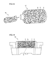
- FIG. 13 is a schematic view that shows a phosphor kneaded matter packaging container and a phosphor kneaded matter containing a transparent resin, calcium gluconate and a red phosphor used for manufacturing a light-emitting device in accordance with one embodiment of the present invention.
- FIG. 14 is a cross-sectional view that shows a light-emitting device in accordance with the embodiment of the present invention.
- FIG. 15 is a schematic view that shows a phosphor kneaded matter packaging container and a phosphor kneaded matter having a three-layer structure containing a transparent resin, a primer and a red phosphor used for manufacturing a light-emitting device in accordance with one embodiment of the present invention.
- FIG. 16 is a cross-sectional view that shows a light-emitting device in accordance with the embodiment of the present invention.
- FIG. 17 is a graph that shows an emission spectrum distribution chart of the light-emitting device manufactured in example 1.
- FIG. 18 is a chromaticity diagram that shows the color reproducibility of an LCD in which the light-emitting device manufactured in example 1 is incorporated as a backlight light source.
- FIG. 19 is a graph that shows an emission spectrum distribution chart of a conventional light-emitting device.
- FIG. 20 is a chromaticity diagram that shows the color reproducibility of an LCD in which the conventional light-emitting device is incorporated as a backlight light source.
- the following description will discuss a light-emitting device manufactured by using a phosphor kneaded matter taken out of phosphor kneaded matter packaging container.
- FIG. 1 is a schematic view that shows a phosphor kneaded matter packaging container 1 and a phosphor kneaded matter 4 containing a transparent resin 2 and a red phosphor 3 used for manufacturing a light-emitting device 5 in accordance with one embodiment of the present invention.
- FIG. 1 is a schematic view that shows a phosphor kneaded matter packaging container 1 and a phosphor kneaded matter 4 containing a transparent resin 2 and a red phosphor 3 used for manufacturing a light-emitting device 5 in accordance with one embodiment of the present invention.
- FIG. 1 is a schematic view that shows a phosphor kneaded matter packaging container 1 and a phosphor kneaded matter 4 containing a transparent resin 2 and a red phosphor 3 used for manufacturing a light-emitting device 5 in accordance with one embodiment of the present invention.
- FIG. 1 is a schematic view that shows a phosphor kneaded matter packaging container
- FIG. 2 shows light-emitting device 5 in which a light-emitting element 6 is placed on a wiring pattern, with the wiring pattern and the upper portion of light-emitting element 6 being connected with each other by a bonding wire, and phosphor kneaded matter 4 containing transparent resin 2 and red phosphor 3 , obtained from phosphor kneaded matter packaging container 1 , and a green phosphor 7 are sealed on the wiring pattern and the light-emitting element with a sealing resin 2 c.
- a gallium nitride (GaN)-based semiconductor that emits primary light in a blue region having a peak wavelength of 430 to 480 nm (more preferably, 440 to 480 nm) is preferably used.
- GaN gallium nitride
- the contribution of the blue light component becomes smaller to cause degradation of the color demonstrating characteristic to fail to be applicable for practical use, and because, when a light-emitting element having a peak wavelength exceeding 480 nm is used, brightness in white color deteriorates to fail to be applicable for practical use.
- transparent resin 2 and red phosphor 3 are taken out of phosphor kneaded matter packaging container 1 as phosphor kneaded matter 4 and used.
- the taking-out process of phosphor kneaded matter 4 need not to be carried out under special. conditions because moisture that might be made in contact with red phosphor 3 is blocked by transparent resin 2 ; however, in order to completely block moisture therefrom, the process is more preferably carried out in a nitrogen atmosphere.
- a mixed matter containing green phosphor 7 and red phosphor 3 at a compounding ratio of 30:70 (weight ratio) is dispersed in a silicone resin (ratio of the silicone resin and the phosphor: 1.00:0.25) so that a wavelength converting unit is formed.
- silicone resin ratio of the silicone resin and the phosphor: 1.00:0.25
- phosphor kneaded matter 4 is prepared by mixing 3.33 g of a silicone resin (agent A (main agent)) having a viscosity of 13500 mP ⁇ s with 5.00 g of a red phosphor by using a high-speed rotating device.
- the viscosity of the resulting red phosphor kneaded matter is set to 20000 mP ⁇ s or more.
- the silicone resin (agent A (main agent)) having a viscosity of 13500 mP ⁇ s
- a silicone resin (agent B (curing agent)) having a viscosity of 35 mP ⁇ s and 0.180 g of a green phosphor indicated by a compounding ratio of Eu 0.05 Si 11.50 Al 0.50 O 0.05 N 15.95 ( ⁇ -type SiAlON) (median diameter: 12.0 ⁇ m) and mixed therein, and by using this mixture, a wavelength converting unit is formed so that light-emitting device 5 shown in FIG. 2 is manufactured.
- the light-emitting element a gallium nitride (GaN)-based semiconductor having a peak wavelength at 450 nm is used.
- transparent resin 2 examples include silicone resin, epoxy resin, urethane resin, norbornane resin, fluorine resin, metal alkoxide, polysilazane, acrylic resin, low-melting point glass and the like.
- Transparent resin 2 preferably contains at least one or more kinds of materials selected from the group consisting of a dispersant, a reflecting agent, and a scattering agent.
- a dispersant, reflecting agent, and scattering agent barium titanate, titan oxide, aluminum oxide, silicon oxide and the like are preferably used.
- red phosphor 3 examples include K 2 (Ti 0.99 Mn 0.01 )F 6 , K 2 (Ti 0.9 Mn 0.1 )F 6 , K 2 (Ti 0.999 Mn 0.001 )F 6 , Na 2 (Zr 0.98 Mn 0.02 )F 6 , Cs 2 (Si 0.95 Mn 0.05 )F 6 , Cs 2 (Sn 0.98 Mn 0.02 )F 6 , K 2 (Ti 0.88 Zr 0.10 Mn 0.02 )F 6 , Na 2 (Ti 0.75 Sn 0.20 Mn 0.05 )F 6 , Cs 2 (Ge 0.999 Mn 0.001 )F 6 , and (K 0.80 Na 0.20 ) 2 (Ti 0.69 Ge 0.30 Mn 0.01 )F 6 ; however, of course, the present invention is not intended to be limited by these.
- examples thereof also include Zn(Ti 0.98 Mn 0.02 )F 6 , Ba(Zr 0.995 Mn 0.005 )F 6 , Ca(Ti 0.995 Mn 0.005 )F 6 , and Sr(Zr 0.98 Mn 0.02 )F 6 ; however, of course, the present invention is not intended to be limited by these.
- green phosphor 7 examples include Eu 0.05 Si 11.50 Al 0.50 O 0.05 N 15.95 , Eu 0.10 Si 11.00 Al 1.00 O 0.10 N 15.90 , Eu 0.30 Si 9.80 Al 2.20 O 0.30 N 15.70 , Eu 0.15 Si 10.00 Al 2.00 O 0.20 N 15.80 , Eu 0.01 Si 11.60 Al 0.40 O 0.01 N 15.99 , and Eu 0.005 Si 11.70 Al 0.30 O 0.03 N 15.97 ; however, of course, the present invention is not intended to be limited by these.
- examples thereof also include 2(Ba 0.70 Sr 0.26 Eu 0.04 ).SiO 2 , 2(Ba 0.57 Sr 0.38 Eu 0.05 )O.SiO 2 , 2(Ba 0.53 Sr 0.43 Eu 0.04 )O.SiO 2 , 2(Ba 0.82 Sr 0.15 Eu 0.03 )O.SiO 2 , 2(Ba 0.46 Sr 0.49 Eu 0.05 )O.SiO 2 , 2(Ba 0.59 Sr 0.35 Eu 0.06 )O.SiO 2 , 2(Ba 0.52 Sr 0.40 Eu 0.08 )O.SiO 2 , 2(Ba 0.85 Sr 0.10 Eu 0.05 )O.SiO 2 , 2(Ba 0.47 Sr 0.50 Eu 0.03 )O.SiO 2 , 2(Ba 0.54 Sr 0.36 Eu 0.10 )O.SiO 2 , 2(Ba 0.69 Sr 0.25 Ca 0.02 Eu 0.04 )O.
- the material for the packaging container is preferably formed by polyethylene or polytetrafluoroethylene that is not eroded by hydrofluoric acid at least on its face to be made in contact with the phosphor kneaded matter.
- the entire packaging container is preferably formed by polyethylene or polytetrafluoroethylene.
- the shape of the packaging container is preferably formed into a tube packaging container having a tube shape or a tube-shaped container so as to form the inside of the packaging container into a multilayer structure.
- This shape is considered to be a simple optimal shape to be used when, upon pressurizing the outside of the packaging container, the material filled in the outermost portion is allowed to coat the member in the center portion of the packaging container.
- the wiring pattern is preferably made of platinum.gold.
- the outermost surface of the pad electrode of semiconductor element 6 is preferably made of platinum.gold.
- sealing resin 2 c epoxy resin, silicone resin, urea resin and the like, which are resin materials having a light-transmitting property, may be used, although not particularly limited thereby.
- the wavelength converting unit may of course contain additives, such as SiO 2 , TiO 2 , ZrO 2 , Al 2 O 3 and Y 2 O 3 , on demand, within a range that does not impair the effects of the present invention.
- the other structures of light-emitting device 5 of the present embodiment are not particularly limited as long as it is allowed to exert the above-mentioned features.
- FIG. 3 is a schematic view that shows a phosphor kneaded matter packaging container 11 and a phosphor kneaded matter 41 having a two-layer structure containing a transparent resin 2 and a red phosphor 3 used for manufacturing a light-emitting device in accordance with one embodiment of the present invention.
- FIG. 3 is a schematic view that shows a phosphor kneaded matter packaging container 11 and a phosphor kneaded matter 41 having a two-layer structure containing a transparent resin 2 and a red phosphor 3 used for manufacturing a light-emitting device in accordance with one embodiment of the present invention.
- FIG. 3 is a schematic view that shows a phosphor kneaded matter packaging container 11 and a phosphor kneaded matter 41 having a two-layer structure containing a transparent resin 2 and a red phosphor 3 used for manufacturing a light-emitting device in accordance with one embodiment of the present invention.
- FIG. 3 is
- FIG. 4 shows a light-emitting device in which a light-emitting element 6 is placed on a wiring pattern, with the wiring pattern and the upper portion of light-emitting element 6 being connected with each other by a bonding wire, and phosphor kneaded matter 41 containing transparent resin 2 and red phosphor 3 , obtained from phosphor kneaded matter packaging container 11 , and a green phosphor 7 are sealed on the wiring pattern and light-emitting element 6 with a sealing resin 2 c.
- a gallium nitride (GaN)-based semiconductor having a peak wavelength at 450 nm is used as light-emitting element 6 .
- a phosphor kneaded matter of red phosphor 3 covered with transparent resin 2 is taken out of phosphor kneaded matter packaging container 11 as phosphor kneaded matter 41 and used.
- Phosphor kneaded matter 41 generated from phosphor kneaded matter packaging container 11 has its inner layer, made from red phosphor 3 , covered with an outer layer made from transparent resin 2 ; therefore, scattering of red phosphor 3 is prevented, and moisture is blocked therefrom, and the resulting effect is that a reaction between red phosphor 3 and moisture is suppressed so that generation of hydrofluoric acid is suppressed.
- transparent resin 2 forming the tube outer layer examples include: silicone resin, epoxy resin, urethane resin, norbornane resin, fluorine resin, metal alkoxide, polysilazane, acrylic resin, low-melting point glass and the like.
- the same material as that of embodiment 1 may be used as a material for red phosphor 3 .
- a mixed matter containing green phosphor 7 and red phosphor 3 at a compounding ratio of 30:70 (weight ratio) is dispersed in a sealing resin (a ratio of the sealing resin and the phosphor is set to 1.00:0.25) so that a wavelength converting unit is formed.
- a sealing resin a ratio of the sealing resin and the phosphor is set to 1.00:0.25
- the same material as that of embodiment 1 may be used as a material for green phosphor 7 .
- FIG. 5 is a schematic view that shows a phosphor kneaded matter packaging container 12 and a phosphor kneaded matter 42 containing a transparent resin 2 , a green phosphor 7 , and a red phosphor 3 used for manufacturing a light-emitting device in accordance with one embodiment of the present invention.
- FIG. 5 is a schematic view that shows a phosphor kneaded matter packaging container 12 and a phosphor kneaded matter 42 containing a transparent resin 2 , a green phosphor 7 , and a red phosphor 3 used for manufacturing a light-emitting device in accordance with one embodiment of the present invention.
- FIG. 5 is a schematic view that shows a phosphor kneaded matter packaging container 12 and a phosphor kneaded matter 42 containing a transparent resin 2 , a green phosphor 7 , and a red phosphor 3 used for manufacturing a light-emitting device in accordance with one embodiment
- FIG. 6 shows a light-emitting device 52 in which a light-emitting element 6 is placed on a wiring pattern, with the wiring pattern and the upper portion of light-emitting element 6 being connected with each other by a bonding wire, and phosphor kneaded matter 42 containing transparent resin 2 , red phosphor 3 , and green phosphor 7 , obtained from phosphor kneaded matter packaging container 12 , is sealed on the wiring pattern and light-emitting element 6 with a sealing resin 2 c.
- a phosphor kneaded matter 42 formed by kneading red phosphor 3 and green phosphor 7 in transparent resin 2 inside the tube, is taken out from phosphor kneaded matter packaging container 12 as phosphor kneaded matter 42 and used.
- green phosphor 7 and red phosphor 3 are blended in transparent resin 2 at desired ratios as the phosphors, a phosphor having a desired chromaticity (in other words, a white light-emitting device) can be obtained. For this reason, no weighing processes are required for the green phosphor and the red phosphor upon forming the light-emitting device.
- phosphor kneaded matter 42 produced by phosphor kneaded matter packaging container 12 , is composed of transparent resin 2 , red phosphor 3 and green phosphor 7 , scattering of red phosphor 3 is prevented, and moisture is blocked therefrom, and the resulting effect is that a reaction between red phosphor 3 and moisture is suppressed so that generation of hydrofluoric acid is suppressed.
- the same material as that of embodiment 1 may be used as a material for red phosphor 3 .
- transparent resin 2 examples include: silicone resin, epoxy resin, urethane resin, norbornane resin, fluorine resin, metal alkoxide, polysilazane, acrylic resin, low-melting point glass and the like.
- Green phosphor 7 and red phosphor 3 in phosphor-knead matter 42 are mixed with each other at a compounding ratio of 30:70 (weight ratio), and preliminarily dispersed in a sealing resin (ratio of the sealing resin and the phosphor: 1.00:0.25).
- a sealing resin ratio of the sealing resin and the phosphor: 1.00:0.25
- FIG. 7 is a schematic view that shows a phosphor kneaded matter packaging container 13 and a phosphor kneaded matter 43 containing a transparent resin 2 and phosphor resin particles 31 corresponding to a red phosphor 3 coated with a coating resin 2 a that are used for manufacturing a light-emitting device in accordance with one embodiment of the present invention.
- FIG. 7 is a schematic view that shows a phosphor kneaded matter packaging container 13 and a phosphor kneaded matter 43 containing a transparent resin 2 and phosphor resin particles 31 corresponding to a red phosphor 3 coated with a coating resin 2 a that are used for manufacturing a light-emitting device in accordance with one embodiment of the present invention.
- FIG. 7 is a schematic view that shows a phosphor kneaded matter packaging container 13 and a phosphor kneaded matter 43 containing a transparent resin 2 and phosphor resin particles 31 corresponding to a red phosphor 3 coated
- FIG. 8 shows a light-emitting device 53 in which a light-emitting element 6 is placed on a wiring pattern, with the wiring pattern and the upper portion of light-emitting element 6 being connected with each other by a bonding wire, and phosphor kneaded matter 43 containing transparent resin 2 and phosphor resin particles 31 serving as red phosphor 3 coated with coating resin 2 a , obtained from phosphor kneaded matter packaging container 13 , as well as green phosphor 7 are sealed on the wiring pattern and light-emitting element 6 with sealing resin 2 c.
- red phosphor 3 is exemplified as a phosphor the entire surface of which is coated with coating resin 2 a ; however, at least one portion of red phosphor 3 may be coated with a thermoplastic resin.
- phosphor kneaded matter 43 generated from phosphor kneaded matter packaging container 13 , is composed of red phosphor 3 the entire surface of which is coated with coating resin 2 a , that is, phosphor resin particles 31 and transparent resin 2 , scattering of red phosphor 3 is prevented, and moisture is blocked therefrom, and the resulting effect is that a reaction between red phosphor 3 and moisture is suppressed so that generation of hydrofluoric acid is suppressed.
- Coating resin 2 a is a thermoplastic resin or a thermosetting resin.
- thermoplastic resin examples include general purpose plastics, such as polyethylene, polypropylene, and polystyrene, thermoplastic plastics, engineering plastics, heat-resistant engineering plastics, thermoplastic elastomer, such as those referred to as four major TPEs of styrene-butadiene type (TPS), olefin type (TPO), polyester type (TPEE), and polyurethane type (TPU), and those of vinyl chloride type (TPVC), polyamide type (TPEA), and fluorine rubber type, and silicone resin.
- TPS styrene-butadiene type
- TPO olefin type
- TPEE polyester type
- TPU polyurethane type
- TPVC vinyl chloride type
- TPEA polyamide type
- fluorine rubber type and silicone resin.
- thermosetting resin examples include: phenol resin, epoxy resin, urea resin, melamine resin, unsaturated polyester resin, polyurethane, and polyimide.
- the shape of the phosphor resin particles can be maintained even after a heating process.
- the same material as that of embodiment 1 may be used as a material for red phosphor 3 .
- thermoplastic resin In the case where coating resin 2 a coating red phosphor 3 is a thermoplastic resin, the thermoplastic resin is melted into sealing resin 2 c when heated, and dispersed in sealing resin 2 c . Thus, light-emitting device 53 is manufactured.
- the light-emitting device may be formed by using phosphor resin particles formed by coating green phosphor 7 and red phosphor 3 with a thermoplastic resin.
- the same material as that of embodiment 1 may be used as a material for green phosphor 7 .
- FIG. 9 is a schematic view that shows a phosphor kneaded matter packaging container 15 and a phosphor kneaded matter 44 containing a primer 22 and a red phosphor 3 to be used for manufacturing a light-emitting device in accordance with one embodiment of the present invention.
- FIG. 9 is a schematic view that shows a phosphor kneaded matter packaging container 15 and a phosphor kneaded matter 44 containing a primer 22 and a red phosphor 3 to be used for manufacturing a light-emitting device in accordance with one embodiment of the present invention.
- FIG. 9 is a schematic view that shows a phosphor kneaded matter packaging container 15 and a phosphor kneaded matter 44 containing a primer 22 and a red phosphor 3 to be used for manufacturing a light-emitting device in accordance with one embodiment of the present invention.
- FIG. 10 shows a light-emitting device in which a light-emitting element 6 is placed on a wiring pattern, with the wiring pattern and the upper portion of light-emitting element 6 being connected with each other by a bonding wire, and phosphor kneaded matter 44 containing primer 22 and red phosphor 3 , obtained from phosphor kneaded matter packaging container 15 , as well as a green phosphor 7 are sealed on the wiring pattern and light-emitting element 6 with sealing resin 2 c.
- red phosphor 3 formed by allowing red phosphor 3 to be coated with primer 22 in a tube, is taken out from phosphor kneaded matter packaging container 15 as phosphor kneaded matter 44 and used.
- phosphor kneaded matter 44 produced by phosphor kneaded matter packaging container 15 , is composed of primer 22 and red phosphor 3 , scattering of red phosphor 3 is prevented, and moisture is blocked therefrom, and the resulting effect is that a reaction between red phosphor 3 and moisture is suppressed so that generation of hydrofluoric acid is suppressed.
- examples of primer 22 include: acryl-based primer, epoxy-based primer, silane-based primer, urethane-based primer, silicone-based primer and phenyl silicone-based primer.
- the presence of the primer layer makes it possible to improve the adhesion between the sealing resin and phosphor so that scattering of red phosphor 3 is prevented more effectively and blocking moisture therefrom is more effectively carried out, and the resulting effect is that a reaction between red phosphor 3 and moisture is suppressed so that generation of hydrofluoric acid is suppressed.
- the same material as that of embodiment 1 may be used as a material for red phosphor 3 .
- a mixture prepared by mixing green phosphor 7 and red phosphor 3 at a compounding ratio of 30:70 (weight ratio), is dispersed in a predetermined sealing resin (a ratio of the sealing resin and the phosphor is set to 1.00:0.25) so that a wavelength converting unit is formed.
- a light-emitting device 54 is manufactured.
- the same material as that of embodiment 1 may be used as green phosphor 7 .
- FIG. 11 is a schematic view that shows a phosphor kneaded matter packaging container 16 and a phosphor kneaded matter 45 containing phosphor primer particles 34 serving as a red phosphor 3 coated with a transparent resin 2 and a primer 22 that are used for manufacturing a light-emitting device in accordance with one embodiment of the present invention.
- FIG. 11 is a schematic view that shows a phosphor kneaded matter packaging container 16 and a phosphor kneaded matter 45 containing phosphor primer particles 34 serving as a red phosphor 3 coated with a transparent resin 2 and a primer 22 that are used for manufacturing a light-emitting device in accordance with one embodiment of the present invention.
- FIG. 11 is a schematic view that shows a phosphor kneaded matter packaging container 16 and a phosphor kneaded matter 45 containing phosphor primer particles 34 serving as a red phosphor 3 coated with a transparent resin 2 and a primer 22 that are used for
- FIG. 12 shows a light-emitting device 55 in which a light-emitting element 6 is placed on a wiring pattern, with the wiring pattern and the upper portion of light-emitting element 6 being connected with each other by a bonding wire, and phosphor kneaded matter 45 containing phosphor primer particles 34 serving as red phosphor 3 coated with sealing resin 2 and primer 22 , obtained from phosphor kneaded matter packaging container 16 , and green phosphor 7 are sealed on the wiring pattern and light-emitting element 6 by sealing resin 2 c.
- Green phosphor 7 and phosphor kneaded manner 45 containing red phosphor 3 are used for the wavelength converting unit.
- Phosphor kneaded matter 45 is taken out from phosphor kneaded matter packaging container 16 as a kneaded matter of phosphor primer particles 34 formed by coating the transparent resin and red phosphor 3 with primer 22 in a tube, and utilized.
- the presence of the primer layer makes it possible to improve the adhesion between the transparent resin and phosphor and to more effectively block the phosphor from moisture, and the resulting effect is that a reaction with the moisture is suppressed so that generation of hydrofluoric acid is suppressed.
- phosphor kneaded matter 45 generated from phosphor kneaded matter packaging container 16 , is composed of phosphor primer particles 34 that are red phosphors 3 coated with transparent resin 2 and primer 22 , scattering of red phosphor 3 is prevented, and moisture is blocked therefrom, and the resulting effect is that a reaction between red phosphor 3 and moisture is suppressed so that generation of hydrofluoric acid is suppressed.
- examples of primer 22 include: an acryl-based primer, an epoxy-based primer, a silane-based primer, a urethane-based primer, a silicone-based primer and a phenyl silicone-based primer.
- the same material as that of embodiment 1 may be used as a material for red phosphor 3 .
- a mixed matter containing green phosphor 7 and red phosphor 3 at a compounding ratio of 30:70 (weight ratio) is dispersed in a predetermined sealing resin (a ratio of the sealing resin and the phosphor is set to 1.00:0.25) so that a wavelength converting unit is formed.
- a predetermined sealing resin a ratio of the sealing resin and the phosphor is set to 1.00:0.25
- the light-emitting device may be manufactured by using phosphor primer particles in which green phosphor 7 and red phosphor 3 are coated with primer 22 .
- FIG. 13 is a schematic view that shows a phosphor kneaded matter packaging container 17 and a phosphor kneaded matter 46 containing a transparent resin 2 , calcium gluconate 8 and a red phosphor 3 that are used for manufacturing a light-emitting device in accordance with one embodiment of the present invention.
- FIG. 13 is a schematic view that shows a phosphor kneaded matter packaging container 17 and a phosphor kneaded matter 46 containing a transparent resin 2 , calcium gluconate 8 and a red phosphor 3 that are used for manufacturing a light-emitting device in accordance with one embodiment of the present invention.
- FIG. 13 is a schematic view that shows a phosphor kneaded matter packaging container 17 and a phosphor kneaded matter 46 containing a transparent resin 2 , calcium gluconate 8 and a red phosphor 3 that are used for manufacturing a light-emitting device in accordance with one embodiment of the present
- FIG. 14 shows a light-emitting device 56 in which a light-emitting element 6 is placed on a wiring pattern, with the wiring pattern and the upper portion of light-emitting element 6 being connected with each other by a bonding wire, and phosphor kneaded matter 46 containing transparent resin 2 , calcium gluconate 8 , and red phosphor 3 , obtained from phosphor kneaded matter packaging container 17 , as well as green phosphor 7 are sealed on the wiring pattern and light-emitting element 6 with sealing resin 2 c.
- Phosphor kneaded matter 46 containing calcium gluconate 8 and red phosphor 3 is used for a wavelength converting unit.
- phosphor kneaded matter 46 is taken out of phosphor kneaded matter packaging container 17 through a tube 17 as a phosphor kneaded matter 46 in which red phosphor 3 , transparent resin 2 and calcium gluconate 8 are kneaded with one another inside the tube and used.
- phosphor kneaded matter 46 generated from phosphor kneaded matter packaging container 17 , is composed of transparent resin 2 , calcium gluconate 8 and red phosphor 3 , scattering of red phosphor 3 is prevented, and moisture is blocked therefrom, and the resulting effect is that a reaction between red phosphor 3 and moisture is suppressed so that generation of hydrofluoric acid is suppressed.
- Hydrogen fluoride causes a reaction in which it combines with calcium ions in the body to generate calcium fluoride, with the result that bones are damaged.
- hydrofluoric acid that is thin in concentration adheres to a part of the body, an acute pain occurs several hours later. This is caused by an influence of calcium fluoride crystal that has been generated.
- calcium ions in the blood are quickly consumed by hydrogen fluoride to cause a reduction in calcium concentration of the blood, often resulting in a serious hypocalcemia. Since the present embodiment has an effect for suppressing generation of hydrofluoric acid, it is possible to reduce the harmful influences to the human body.
- calcium gluconate (molecular formula: C 12 H 22 CaO 14 .H 2 O) is white crystalline powder or granulated powder.
- Gluconate has such a characteristic as to be easily absorbed by the body. Calcium ions taken into the body as gluconate are combined with soluble fluoride ions to form insoluble calcium fluoride so that the soluble fluoride ions are rendered innocuous.
- calcium gluconate is used; however, any calcium compound may be used as long as the compound is innocuous to a living body.
- examples thereof include at least one compound selected from the group consisting of calcium borogluconate, calcium glycerophosphate, calcium chloride, calcium lactate, calcium propionate, calcium pantothenate, calcium citrate and calcium hydrogenphosphate.
- the above-mentioned calcium compounds can be used in the same manner as in calcium gluconate, and the same effects can be obtained.
- the same materials as those of embodiment 1 may be used as materials for red phosphor 3 and transparent resin 2 .
- the rate of calcium gluconate 8 is set to 30 to 50% in weight ratio relative to transparent resin 2 .
- a mixed matter containing green phosphor 7 and red phosphor 3 at a compounding ratio of 30:70 (weight ratio) is dispersed in a predetermined resin (ratio of resin 2 and the phosphor: 1.00:0.25) so that a wavelength converting unit is formed.
- a predetermined resin ratio of resin 2 and the phosphor: 1.00:0.25
- the same material as that of embodiment 1 may be used as a material for green phosphor 7 .
- FIG. 15 is a schematic view that shows a phosphor kneaded matter packaging container 18 and a phosphor kneaded matter 47 having a three-layer structure containing a transparent resin 2 , a primer 22 , and a red phosphor 3 that are used for manufacturing a light-emitting device in accordance with one embodiment of the present invention.
- FIG. 15 is a schematic view that shows a phosphor kneaded matter packaging container 18 and a phosphor kneaded matter 47 having a three-layer structure containing a transparent resin 2 , a primer 22 , and a red phosphor 3 that are used for manufacturing a light-emitting device in accordance with one embodiment of the present invention.
- FIG. 15 is a schematic view that shows a phosphor kneaded matter packaging container 18 and a phosphor kneaded matter 47 having a three-layer structure containing a transparent resin 2 , a primer 22 , and a red phosphor 3 that
- FIG. 16 shows a light-emitting device 57 in which a light-emitting element 6 is placed on a wiring pattern, with the wiring pattern and the upper portion of light-emitting element 6 being connected with each other by a bonding wire, and phosphor kneaded matter 47 containing transparent resin 2 , primer 22 , and red phosphor 3 , obtained from phosphor kneaded matter packaging container 18 , as well as green phosphor 7 are sealed on the wiring pattern and light-emitting element 6 by sealing resin 2 c.
- Green phosphor 7 and phosphor kneaded matter 47 containing red phosphor 3 are used for a wavelength converting unit.
- phosphor kneaded matter 47 is taken out of phosphor kneaded matter packaging container 18 through a phosphor tube 18 as a phosphor kneaded matter prepared by coating red phosphor 3 with primer 22 and transparent resin 2 inside the tube and used.
- phosphor kneaded matter 47 generated from phosphor kneaded matter packaging container 18 , is composed of transparent resin 2 forming an outer layer, primer 22 forming an inner layer and red phosphor 3 located in the center, scattering of red phosphor 3 is prevented, and moisture is blocked therefrom, and the resulting effect is that a reaction between red phosphor 3 and moisture is suppressed so that generation of hydrofluoric acid is suppressed.
- the same materials as those of embodiment 1 may be used as materials for red phosphor 3 and transparent resin 2 .
- the same material as that of embodiment 6 may be used as a material for primer 22 .
- a mixed matter containing green phosphor 7 and red phosphor 3 at a compounding ratio of 30:70 (weight ratio) is dispersed in a predetermined sealing resin (ratio of sealing resin and the phosphor: 1.00:0.25) so that a wavelength converting unit is formed.
- a predetermined sealing resin ratio of sealing resin and the phosphor: 1.00:0.25
- the same material as that of embodiment 3 may be used as a material for green phosphor 7 .
- any of the above-mentioned green phosphor and red phosphor to be used for the light-emitting device of the present embodiment are known phosphors, and can be manufactured by using a conventionally known method on demand, or can be obtained as commercial products.
- FIG. 1 shows a tube-shaped packaging container (made of polyethylene) in which a silicone resin serving as transparent resin 2 and K 2 (Ti 0.99 Mn 0.01 )F 6 , that is, red fluoride phosphor serving as red phosphor 3 , are kneaded in a tube.
- a packaging container material forms phosphor kneaded matter packaging container 1 filled with phosphor kneaded matter 4 that causes a generation of hydrofluoric acid due to a reaction between the phosphor and moisture.
- phosphor kneaded matter 4 has its red phosphor 3 coated with a silicone resin serving as transparent resin 2 , scattering of red phosphor 3 is prevented, and moisture is blocked therefrom, and the resulting effect is that a reaction between red phosphor 3 and moisture is suppressed so that generation of hydrofluoric acid is suppressed.
- the packaging container material is prepared as polyethylene.
- light-emitting device 5 as shown in FIG. 2 was manufactured.
- GaN gallium nitride
- phosphor kneaded matter 4 containing Eu 0.05 Si 11.50 Al 0.50 O 0.05 N 15.95 ( ⁇ -type SiAlON) as green phosphor 7 and K 2 (Ti 0.99 Mn 0.01 )F 6 as red phosphor 3 was used as the wavelength converting unit.
- a kneaded matter of transparent resin 2 and K 2 (Ti 0.99 Mn 0.01 )F 6 serving as red phosphor 3 was taken out of phosphor kneaded matter packaging container 1 , and used as phosphor kneaded matter 4 .
- a mixed matter containing green phosphor 7 and red phosphor 3 at a compounding ratio of 30:70 (weight ratio) was dispersed in sealing resin 2 c made from epoxy resin (ratio of the sealing resin and the phosphor: 1.00:0.25) so that a wavelength converting unit was formed.
- sealing resin 2 c made from epoxy resin (ratio of the sealing resin and the phosphor: 1.00:0.25) so that a wavelength converting unit was formed.
- Light-emitting devices obtained in example 1 were evaluated for brightness and color reproducibility (NTSC ratio). With respect to the brightness, each device was lit on under a forward current of (IF) 20 mA, and measurements were carried out by converting white light from the light-emitting device into photocurrent. Moreover, with respect to the color reproducibility (NTSC ratio), the manufactured light-emitting device was incorporated into a commercial LCD television display as its backlight light source, and measurements were carried out by using a Bm 5 made by Topcon Corporation so that the corresponding value was obtained. The color reproducibility (NTSC ratio) was remarkably improved to 86.4% to ensure that the device had desirable characteristics for backlights of middle and small-type LCDs.
- IF forward current of
- NTSC ratio color reproducibility
- the NTSC ratio relates to a chromaticity diagram of XYZ colorimetric system of respective colors of red, green and blue, determined by NTSC (National Television System Committee), and chromaticity coordinates (x, y) respectively correspond to red (0.670, 0.330), green (0.210, 0.710) and blue (0.140, 0.080), and the NTSC ratio represents a ratio relative to a triangular area obtained by connecting the respective chromaticity coordinates of red, green and blue.
- FIG. 17 is a graph that shows an emission spectrum distribution of a light-emitting device manufactured in example 1 of the present invention, and in FIG. 17 , the axis of ordinate represents the intensity (arbitrary unit) and the axis of abscissa represents the wavelength (nm).
- FIG. 18 is a chromaticity diagram (CIE1931) showing the color reproducibility of an LCD in which the light-emitting device manufactured in example 1 of the present invention is incorporated as a backlight light source.
- FIG. 19 is a graph that shows an emission spectrum distribution of a conventional light-emitting device (comparative example) in which yellow luminescent phosphor ((Y 0.40 Gd 0.45 Ce 0.15 ) 3 Al 5 O 12 ) is used, and FIG.
- FIGS. 17 and 19 are chromaticity diagrams showing the color reproducibility of an LCD in which this light-emitting device is incorporated as a backlight light source.
- the emission spectrum distributions of the light-emitting devices shown in FIGS. 17 and 19 are based upon the results of measurements carried out by a MCPD-2000 (made by Otsuka Electronics Co., Ltd.).
- the color reproducibility shown in each of FIGS. 18 and 20 is based upon the results of measurements carried out by a Bm5 (made by Topcon Corporation). As indicated by FIGS.
- the light-emitting device of the present invention allows the wavelength converting unit to effectively absorb light emission from a light-emitting element, and makes it possible to emit white light with high efficiency and also to provide white light that is remarkably superior in color reproducibility (NTSC ratio).
- FIG. 3 shows a phosphor kneaded matter packaging container 11 in which transparent resin 2 forming the packaging container outer layer is an epoxy resin and red phosphor 3 forms the packaging container inner layer, and a phosphor kneaded matter obtained from the container.
- transparent resin 2 forming the packaging container outer layer is an epoxy resin
- red phosphor 3 forms the packaging container inner layer
- red phosphor 3 forms the packaging container inner layer
- red phosphor 3 phosphor kneaded matter obtained from the container.
- K 2 (Ti 0.995 Mn 0.005 )F 6 was used as red phosphor 3 .
- a light-emitting device 51 as shown in FIG. 4 was manufactured.
- a gallium nitride (GaN)-based semiconductor having a peak wavelength at 440 nm was used as light-emitting element 6 , and a phosphor kneaded matter 41 containing 2(Ba 0.70 Sr 0.26 Eu 0.04 ).SiO 2 serving as green phosphor 7 and K 2 (Ti 0.995 Mn 0.005 )F 6 serving as red phosphor 3 was used as the wavelength converting unit.
- a phosphor kneaded matter 41 composed of red phosphor, K 2 (Ti 0.995 Mn 0.005 )F 6 , coated with the epoxy resin serving as transparent resin 2 , was taken out of phosphor kneaded matter packaging container 11 , and used as phosphor kneaded matter 41 .
- a mixed matter containing green phosphor 7 and red phosphor 3 at a compounding ratio of 30:70 (weight ratio) was dispersed in sealing resin 2 c made from epoxy resin (a ratio of the epoxy resin and the phosphor was 1.00:0.25) so that a wavelength converting unit was manufactured.
- sealing resin 2 c made from epoxy resin (a ratio of the epoxy resin and the phosphor was 1.00:0.25) so that a wavelength converting unit was manufactured.
- a light-emitting device of example 2 was manufactured.
- the color reproducibility (NTSC ratio) was incorporated into a commercial LCD television display as its backlight light source, and measurements were carried out by using a Bm 5 made by Topcon Corporation, and the corresponding value was obtained.
- the color reproducibility (NTSC ratio) was remarkably improved to 88.1% to ensure that the device had desirable characteristics for backlights of middle and small-type LCDs.
- FIG. 5 shows a phosphor kneaded matter packaging container 12 and a phosphor kneaded matter 42 that is formed by blending green phosphor 7 and red phosphor 3 at desired ratios in transparent resin 2 made from a silicone resin (ratio of transparent resin 2 and the phosphor: 1.00:0.25) inside the packaging container (made from polytetrafluoroethylene).
- transparent resin 2 made from a silicone resin (ratio of transparent resin 2 and the phosphor: 1.00:0.25) inside the packaging container (made from polytetrafluoroethylene).
- Eu 0.30 Si 9.80 Al 2.20 O 0.30 N 15.70 was used phosphor 7 and Na 2 (Ti 0.895 Zr 0.100 Mn 0.005 )F 6 was used as red phosphor 3 .
- a light-emitting device 52 as shown in FIG. 6 was manufactured.
- a gallium nitride (GaN)-based semiconductor having a peak wavelength at 430 nm was used as light-emitting element 6
- phosphor kneaded matter 42 containing Eu 0.30 Si 9.80 Al 2.20 O 0.30 N 15.70 as green phosphor 7 and Na 2 (Ti 0.895 Zr 0.100 Mn 0.005 )F 6 as red phosphor 3 at a ratio of 30:70 (weight ratio) was used as the wavelength converting unit.
- a phosphor kneaded matter formed by kneading Eu 0.30 Si 9.80 Al 2.20 O 0.30 N 15.70 and Na 2 (Ti 0.895 Zr 0.100 Mn 0.005 )F 6 in a silicone resin inside the packaging container, was taken out of phosphor kneaded matter packaging container 12 , and used as phosphor kneaded matter 42 .
- Phosphor kneaded matter 42 containing green phosphor 7 and red phosphor 3 at a compounding ratio of 30:70 (weight ratio) was preliminarily dispersed in sealing resin 2 c made from silicone resin (ratio of the sealing resin and the phosphor: 1.00:0.25).
- sealing resin 2 c made from silicone resin (ratio of the sealing resin and the phosphor: 1.00:0.25).
- a light-emitting device 52 of example 3 was manufactured.
- the manufactured light-emitting device was incorporated into a commercial LCD television display as its backlight light source, and measurements were carried out by using a Bm 5 made by Topcon Corporation, and the corresponding value was obtained.
- the color reproducibility (NTSC ratio) was remarkably improved to 86.4% to ensure that the device had desirable characteristics for backlights of middle and small-type LCDs.
- FIG. 7 shows a phosphor kneaded matter packaging container 13 and a phosphor kneaded matter 43 prepared by kneading red phosphor 3 the entire surface of which is coated with transparent resin 2 made from a silicone resin and coating resin 2 a made from a silicone resin inside the packaging container.
- transparent resin 2 made from a silicone resin
- coating resin 2 a made from a silicone resin inside the packaging container.
- Cs 2 (Ti 0.790 Si 0.200 Mn 0.010 )F 6 was used as red phosphor 3 .
- a light-emitting device 53 as shown in FIG. 8 was manufactured.
- a gallium nitride (GaN)-based semiconductor having a peak wavelength at 480 nm was used as light-emitting element 6 , and a mixture, obtained by mixing Eu 0.15 Si 10.00 Al 2.00 O 0.20 N 15.80 as green phosphor 7 and Cs 2 (Ti 0.790 Si 0.200 Mn 0.010 )F 6 obtained from phosphor kneaded matter 43 as red phosphor 3 at a ratio of 30:70 (weight ratio), was dispersed in a predetermined sealing resin 2 c (ratio of the sealing resin and the phosphor: 1.00:0.25) so that a wavelength converting unit was formed.
- GaN gallium nitride
- phosphor resin particles 31 made from Cs 2 (Ti 0.790 Si 0.200 Mn 0.010 )F 6 , that were coated with coating resin 2 a made from silicone resin, were taken out of phosphor kneaded matter packaging container 11 as phosphor kneaded matter 43 , and used.
- coating resin 2 a with which red phosphor 3 was coated was a thermoplastic resin, the resin was melted down into the sealing resin when heated, and dispersed in the resin. Thus, a light-emitting device 53 of example 4 was manufactured.
- the manufactured light-emitting device was incorporated into a commercial LCD television display as its backlight light source, and measurements were carried out by using a Bm 5 made by Topcon Corporation, and the corresponding value was obtained.
- the color reproducibility (NTSC ratio) was remarkably improved to 87.9% to ensure that the device had desirable characteristics for backlights of middle and small-type LCDs.
- FIG. 9 shows a phosphor kneaded matter packaging container 15 and a phosphor kneaded matter 44 in which an acryl-based primer serving as primer 22 and red phosphor 3 are kneaded in the packaging container.
- Cs 2 (Ti 0.790 Si 0.200 Mn 0.010 )F 6 was used as red phosphor 3 .
- a light-emitting device 54 as shown in FIG. 10 was manufactured.
- a gallium nitride (GaN)-based semiconductor having a peak wavelength at 455 nm was used as light-emitting element 6
- 2(Ba 0.82 Sr 0.15 Eu 0.03 )O.SiO 2 serving as green phosphor 7 and Cs 2 (Ti 0.790 Si 0.200 Mn 0.010 )F 6 obtained from phosphor kneaded matter 44 as red phosphor 3 were used as the wavelength converting unit.
- phosphor kneaded matter 44 a phosphor kneaded matter 44 in which Cs 2 (Ti 0.790 Si 0.200 Mn 0.010 )F 6 serving as red phosphor 3 was coated with primer 22 was taken out of phosphor kneaded matter packaging container 15 , and used.
- the manufactured light-emitting device was incorporated into a commercial LCD television display as its backlight light source, and measurements were carried out by using a Bm 5 made by Topcon Corporation, and the corresponding value was obtained.
- the color reproducibility (NTSC ratio) was remarkably improved to 88.5% to ensure that the device had desirable characteristics for backlights of middle and small-type LCDs.
- FIG. 11 shows a phosphor kneaded matter packaging container 16 and a phosphor kneaded matter that is made from transparent resin 2 and red phosphor 3 made of phosphor primer particles 34 coated with an acryl-based primer, and contained in the packaging container.
- Ba(Ti 0.990 Mn 0.010 )F 6 was used as red phosphor 3 .
- a light-emitting device 55 as shown in FIG. 12 was manufactured.
- a gallium nitride (GaN)-based semiconductor having a peak wavelength at 460 nm was used as light-emitting element 6 , and Eu 0.01 Si 11.60 Al 0.40 O 0.01 N 15.99 serving as green phosphor 7 and Ba(Ti 0.990 Mn 0.010 )F 6 obtained from phosphor kneaded matter 45 as red phosphor 3 were used as the wavelength converting unit.
- phosphor primer particles 34 formed by coating Ba(Ti 0.990 Mn 0.010 )F 6 serving as red phosphor 3 with primer 22 were taken out of packaging container 16 , and used.
- the manufactured light-emitting device was incorporated into a commercial LCD television display as its backlight light source, and measurements were carried out by using a Bm 5 made by Topcon Corporation so that the corresponding value was obtained.
- the color reproducibility (NTSC ratio) was remarkably improved to 87.8% to ensure that the device had desirable characteristics for backlights of middle and small-type LCDs.
- FIG. 13 shows a phosphor kneaded matter packaging container 17 and a phosphor kneaded matter 46 in which silicone resin serving as transparent resin 2 , calcium gluconate 8 (molecular formula: C 12 H 22 CaO 14 .H 2 O) and red phosphor 3 are kneaded in the packaging container.
- silicone resin serving as transparent resin 2
- calcium gluconate 8 molecular formula: C 12 H 22 CaO 14 .H 2 O
- red phosphor 3 molecular formula: C 12 H 22 CaO 14 .H 2 O
- a light-emitting device 56 as shown in FIG. 14 was manufactured.
- a gallium nitride (GaN)-based semiconductor having a peak wavelength at 445 nm was used as light-emitting element 6
- 2(Ba 0.85 Sr 0.10 Eu 0.05 )O.SiO 2 serving as green phosphor 7 and (K 0.80 Na 0.20 ) 2 (Ti 0.690 Ge 0.300 Mn 0.010 )F 6 obtained from phosphor kneaded matter 46 as red phosphor 3 were used as the wavelength converting unit.
- phosphor kneaded matter 46 a phosphor kneaded matter 46 in which (K 0.80 Na 0.20 ) 2 (Ti 0.690 Ge 0.300 Mn 0.010 )F 6 serving as red phosphor 3 was kneaded together with transparent resin 2 and calcium gluconate 8 was taken out of phosphor kneaded matter packaging container 17 , and used.
- the rate of calcium gluconate 8 was set to 30% in weight ratio relative to transparent resin 2 .
- the manufactured light-emitting device was incorporated into a commercial LCD television display as its backlight light source, and measurements were carried out by using a Bm 5 made by Topcon Corporation, and the corresponding value was obtained.
- the color reproducibility (NTSC ratio) was remarkably improved to 88.5% to ensure that the device had desirable characteristics for backlights of middle and small-type LCDs.
- FIG. 15 shows a phosphor kneaded matter packaging container 18 having a three-layer structure inside the packaging container and a phosphor kneaded matter having a layer made from primer 22 formed between transparent resin 2 and red phosphor 3 .
- Zn(Ti 0.849 Sn 0.150 Mn 0.001 )F 6 was used as red phosphor 3 .
- a light-emitting device 57 as shown in FIG. 16 was manufactured.
- a gallium nitride (GaN)-based semiconductor having a peak wavelength at 470 nm was used as light-emitting element 6
- Eu 0.005 Si 11.70 Al 0.30 O 0.03 N 15.97 serving as green phosphor 7 and Zn(Ti 0.849 Sn 0.150 Mn 0.001 )F 6 obtained from phosphor kneaded matter 47 as red phosphor 3 were used as the wavelength converting unit.
- a mixed matter containing green phosphor 7 and red phosphor 3 at a compounding ratio of 30:70 (weight ratio) was dispersed in sealing resin 2 c made from silicone resin (ratio of the sealing resin and the phosphor: 1.00:0.25) so that a wavelength converting unit was manufactured.
- sealing resin 2 c made from silicone resin (ratio of the sealing resin and the phosphor: 1.00:0.25) so that a wavelength converting unit was manufactured.
- a light-emitting device of example 8 was manufactured.
- the manufactured light-emitting device was incorporated into a commercial LCD television display as its backlight light source, and measurements were carried out by using a Bm 5 made by Topcon Corporation, and the corresponding value was obtained.
- the color reproducibility (NTSC ratio) was remarkably improved to 88.4% to ensure that the device had desirable characteristics for backlights of middle and small-type LCDs.
Landscapes
- Led Device Packages (AREA)
- Luminescent Compositions (AREA)
- Led Devices (AREA)
Abstract
Description
Claims (13)
Applications Claiming Priority (4)
| Application Number | Priority Date | Filing Date | Title |
|---|---|---|---|
| JP2008-187584 | 2008-07-18 | ||
| JP2008187584 | 2008-07-18 | ||
| JP2009-105999 | 2009-04-24 | ||
| JP2009105999A JP5239043B2 (en) | 2008-07-18 | 2009-04-24 | Light emitting device and method for manufacturing light emitting device |
Publications (2)
| Publication Number | Publication Date |
|---|---|
| US20100013373A1 US20100013373A1 (en) | 2010-01-21 |
| US8427042B2 true US8427042B2 (en) | 2013-04-23 |
Family
ID=41529708
Family Applications (1)
| Application Number | Title | Priority Date | Filing Date |
|---|---|---|---|
| US12/502,691 Expired - Fee Related US8427042B2 (en) | 2008-07-18 | 2009-07-14 | Light-emitting device and method for manufacturing light-emitting device |
Country Status (3)
| Country | Link |
|---|---|
| US (1) | US8427042B2 (en) |
| JP (1) | JP5239043B2 (en) |
| CN (1) | CN101630714B (en) |
Cited By (14)
| Publication number | Priority date | Publication date | Assignee | Title |
|---|---|---|---|---|
| US8906724B2 (en) | 2013-03-15 | 2014-12-09 | General Electric Company | Color stable red-emitting phosphors |
| US9371481B2 (en) | 2014-06-12 | 2016-06-21 | General Electric Company | Color stable red-emitting phosphors |
| US9376615B2 (en) | 2014-06-12 | 2016-06-28 | General Electric Company | Color stable red-emitting phosphors |
| US9385282B2 (en) | 2014-06-12 | 2016-07-05 | General Electric Company | Color stable red-emitting phosphors |
| US9388336B2 (en) | 2013-12-13 | 2016-07-12 | General Electric Company | Processes for preparing color stable manganese-doped complex fluoride phosphors |
| US9399732B2 (en) | 2013-08-22 | 2016-07-26 | General Electric Company | Processes for preparing color stable manganese-doped phosphors |
| US9567516B2 (en) | 2014-06-12 | 2017-02-14 | General Electric Company | Red-emitting phosphors and associated devices |
| US9580648B2 (en) | 2013-03-15 | 2017-02-28 | General Electric Company | Color stable red-emitting phosphors |
| US9598636B2 (en) | 2012-12-28 | 2017-03-21 | Shin-Etsu Chemical Co., Ltd. | Phosphor surface treatment method |
| US9929319B2 (en) | 2014-06-13 | 2018-03-27 | General Electric Company | LED package with red-emitting phosphors |
| US9982190B2 (en) | 2015-02-20 | 2018-05-29 | General Electric Company | Color stable red-emitting phosphors |
| US10047286B2 (en) | 2014-10-27 | 2018-08-14 | General Electric Company | Color stable red-emitting phosphors |
| US10214687B2 (en) | 2014-01-30 | 2019-02-26 | Shin-Etsu Chemical Co., Ltd. | Method for producing and method for processing complex fluoride phosphor |
| US10230022B2 (en) | 2014-03-13 | 2019-03-12 | General Electric Company | Lighting apparatus including color stable red emitting phosphors and quantum dots |
Families Citing this family (23)
| Publication number | Priority date | Publication date | Assignee | Title |
|---|---|---|---|---|
| KR101592836B1 (en) | 2008-02-07 | 2016-02-05 | 미쓰비시 가가꾸 가부시키가이샤 | Semiconductor light emitting device, backlighting device, color image display device and phosphor used for those devices |
| JP2011210891A (en) * | 2010-03-29 | 2011-10-20 | Hitachi Chem Co Ltd | Wavelength-converting solar cell sealing sheet, and solar cell module |
| US20110309393A1 (en) * | 2010-06-21 | 2011-12-22 | Micron Technology, Inc. | Packaged leds with phosphor films, and associated systems and methods |
| JP5375906B2 (en) * | 2011-09-13 | 2013-12-25 | 日亜化学工業株式会社 | Fluoride phosphor and light emitting device using the same |
| US9982189B2 (en) | 2012-12-28 | 2018-05-29 | Shin-Etsu Chemical Co., Ltd. | Wavelength conversion member and light-emitting device |
| EP2940742A4 (en) | 2012-12-28 | 2016-07-13 | Shinetsu Chemical Co | LIGHT EMITTING DEVICE |
| US9590148B2 (en) | 2014-03-18 | 2017-03-07 | GE Lighting Solutions, LLC | Encapsulant modification in heavily phosphor loaded LED packages for improved stability |
| US9546318B2 (en) * | 2014-05-01 | 2017-01-17 | General Electric Company | Process for preparing red-emitting phosphors |
| JP6657735B2 (en) * | 2014-10-07 | 2020-03-04 | 日亜化学工業株式会社 | Light emitting device |
| US10490711B2 (en) | 2014-10-07 | 2019-11-26 | Nichia Corporation | Light emitting device |
| CN104362230A (en) * | 2014-12-03 | 2015-02-18 | 广东威创视讯科技股份有限公司 | Method for improving yellow ring phenomenon of white-light LED (light emitting diode) and white-light LED structure |
| JP2016152276A (en) * | 2015-02-16 | 2016-08-22 | 日亜化学工業株式会社 | Light emission device |
| JP6354626B2 (en) * | 2015-03-09 | 2018-07-11 | 豊田合成株式会社 | Method for manufacturing light emitting device |
| US9882107B2 (en) * | 2016-01-12 | 2018-01-30 | Citizen Electronics Co., Ltd. | LED package with covered bonding wire |
| JP2018137321A (en) * | 2017-02-21 | 2018-08-30 | シャープ株式会社 | Light-emitting device and image display device |
| US10763414B2 (en) * | 2017-12-18 | 2020-09-01 | Rohm Co., Ltd. | Semiconductor light-emitting device |
| CN111699420B (en) * | 2018-02-14 | 2023-01-13 | 日本特殊陶业株式会社 | Optical wavelength conversion device |
| JP7095937B2 (en) * | 2018-03-09 | 2022-07-05 | ミネベアミツミ株式会社 | Manufacturing method of fluorescent sheet |
| CN113826225A (en) | 2019-03-18 | 2021-12-21 | 英特曼帝克司公司 | Encapsulated white light emitting device including photoluminescent layered structure |
| US11781714B2 (en) | 2019-03-18 | 2023-10-10 | Bridgelux, Inc. | LED-filaments and LED-filament lamps |
| US11342311B2 (en) | 2019-03-18 | 2022-05-24 | Intematix Corporation | LED-filaments and LED-filament lamps utilizing manganese-activated fluoride red photoluminescence material |
| CN113841238A (en) | 2019-03-18 | 2021-12-24 | 英特曼帝克司公司 | LED Filament |
| US10468564B1 (en) * | 2019-03-18 | 2019-11-05 | Intematix Corporation | Packaged white light emitting device comprising photoluminescence layered structure |
Citations (15)
| Publication number | Priority date | Publication date | Assignee | Title |
|---|---|---|---|---|
| JPH1036827A (en) | 1996-07-25 | 1998-02-10 | Fujitsu Ltd | Phosphor particles and method for forming protective layer thereof |
| JPH10118666A (en) | 1996-10-23 | 1998-05-12 | Komatsu Ltd | Neutralization of acid-containing aqueous solution with calcium base |
| US20020037478A1 (en) * | 1997-04-14 | 2002-03-28 | Naoki Kimura | Fluorescent pattern, process for preparing the same, organic alkali developing solution for forming the same, emulsion developing solution for forming the same and back plate for plasma display using the same |
| US20040149958A1 (en) | 2002-03-05 | 2004-08-05 | Chua Bee Yin | Coated phosphor filler and a method of forming the coated phosphor filler |
| JP2004281432A (en) | 2003-03-12 | 2004-10-07 | Nichia Chem Ind Ltd | Nitride semiconductor device and method of manufacturing the same |
| US20060169998A1 (en) | 2005-02-02 | 2006-08-03 | Gelcore, Llc | Red line emitting phosphor materials for use in LED applications |
| US20060226759A1 (en) * | 2005-03-06 | 2006-10-12 | Sharp Kabushiki Kaisha | Light emitting device and fabricating method thereof |
| JP2006321966A (en) | 2004-09-28 | 2006-11-30 | Kyocera Corp | Fluorescent structure, ultrafine particle structure and composite, light emitting device, and light emitting device assembly |
| US20070046169A1 (en) * | 2001-09-03 | 2007-03-01 | Matsushita Electric Industrial Co., Ltd. | Light-emitting semiconductor device, light-emitting system and method for fabricating light-emitting semiconductor device |
| JP2007180483A (en) | 2005-11-30 | 2007-07-12 | Sharp Corp | Light-emitting device |
| WO2008001799A1 (en) | 2006-06-27 | 2008-01-03 | Mitsubishi Chemical Corporation | Illuminating device |
| JP2008150518A (en) | 2006-12-19 | 2008-07-03 | Sharp Corp | Wavelength conversion member and light emitting device |
| JP2008166825A (en) | 2007-01-02 | 2008-07-17 | Samsung Electro Mech Co Ltd | White light emitting device and light source module for LCD backlight using the same |
| US20080197376A1 (en) * | 2005-02-28 | 2008-08-21 | Braune Bert | Method for Producing an Optical, Radiation-Emitting Component and Optical, Radiation-Emitting Component |
| JP2008198951A (en) | 2007-02-15 | 2008-08-28 | Nitto Denko Corp | Method for producing epoxy resin composition for sealing optical semiconductor element |
Family Cites Families (1)
| Publication number | Priority date | Publication date | Assignee | Title |
|---|---|---|---|---|
| JPH06338389A (en) * | 1993-05-27 | 1994-12-06 | Mitsubishi Cable Ind Ltd | El luminescence element |
-
2009
- 2009-04-24 JP JP2009105999A patent/JP5239043B2/en not_active Expired - Fee Related
- 2009-07-14 US US12/502,691 patent/US8427042B2/en not_active Expired - Fee Related
- 2009-07-17 CN CN2009101399751A patent/CN101630714B/en not_active Expired - Fee Related
Patent Citations (18)
| Publication number | Priority date | Publication date | Assignee | Title |
|---|---|---|---|---|
| JPH1036827A (en) | 1996-07-25 | 1998-02-10 | Fujitsu Ltd | Phosphor particles and method for forming protective layer thereof |
| JPH10118666A (en) | 1996-10-23 | 1998-05-12 | Komatsu Ltd | Neutralization of acid-containing aqueous solution with calcium base |
| US20020037478A1 (en) * | 1997-04-14 | 2002-03-28 | Naoki Kimura | Fluorescent pattern, process for preparing the same, organic alkali developing solution for forming the same, emulsion developing solution for forming the same and back plate for plasma display using the same |
| US20070046169A1 (en) * | 2001-09-03 | 2007-03-01 | Matsushita Electric Industrial Co., Ltd. | Light-emitting semiconductor device, light-emitting system and method for fabricating light-emitting semiconductor device |
| US20040149958A1 (en) | 2002-03-05 | 2004-08-05 | Chua Bee Yin | Coated phosphor filler and a method of forming the coated phosphor filler |
| JP2004281432A (en) | 2003-03-12 | 2004-10-07 | Nichia Chem Ind Ltd | Nitride semiconductor device and method of manufacturing the same |
| JP2006321966A (en) | 2004-09-28 | 2006-11-30 | Kyocera Corp | Fluorescent structure, ultrafine particle structure and composite, light emitting device, and light emitting device assembly |
| US20060169998A1 (en) | 2005-02-02 | 2006-08-03 | Gelcore, Llc | Red line emitting phosphor materials for use in LED applications |
| US20080197376A1 (en) * | 2005-02-28 | 2008-08-21 | Braune Bert | Method for Producing an Optical, Radiation-Emitting Component and Optical, Radiation-Emitting Component |
| US20060226759A1 (en) * | 2005-03-06 | 2006-10-12 | Sharp Kabushiki Kaisha | Light emitting device and fabricating method thereof |
| JP2007180483A (en) | 2005-11-30 | 2007-07-12 | Sharp Corp | Light-emitting device |
| WO2007100824A2 (en) | 2006-02-28 | 2007-09-07 | Lumination, Llc | Red line emitting phosphors for use in led applications |
| WO2008001799A1 (en) | 2006-06-27 | 2008-01-03 | Mitsubishi Chemical Corporation | Illuminating device |
| US20090267484A1 (en) | 2006-06-27 | 2009-10-29 | Mitsubishi Chemical Corporation | Illuminating device |
| JP2008150518A (en) | 2006-12-19 | 2008-07-03 | Sharp Corp | Wavelength conversion member and light emitting device |
| JP2008166825A (en) | 2007-01-02 | 2008-07-17 | Samsung Electro Mech Co Ltd | White light emitting device and light source module for LCD backlight using the same |
| US20080180948A1 (en) | 2007-01-02 | 2008-07-31 | Samsung Electro-Mechanics Co., Ltd. | White light emitting device and light source module for liquid crystal display backlight using the same |
| JP2008198951A (en) | 2007-02-15 | 2008-08-28 | Nitto Denko Corp | Method for producing epoxy resin composition for sealing optical semiconductor element |
Cited By (15)
| Publication number | Priority date | Publication date | Assignee | Title |
|---|---|---|---|---|
| US9598636B2 (en) | 2012-12-28 | 2017-03-21 | Shin-Etsu Chemical Co., Ltd. | Phosphor surface treatment method |
| US8906724B2 (en) | 2013-03-15 | 2014-12-09 | General Electric Company | Color stable red-emitting phosphors |
| US9698314B2 (en) | 2013-03-15 | 2017-07-04 | General Electric Company | Color stable red-emitting phosphors |
| US9580648B2 (en) | 2013-03-15 | 2017-02-28 | General Electric Company | Color stable red-emitting phosphors |
| US9399732B2 (en) | 2013-08-22 | 2016-07-26 | General Electric Company | Processes for preparing color stable manganese-doped phosphors |
| US9388336B2 (en) | 2013-12-13 | 2016-07-12 | General Electric Company | Processes for preparing color stable manganese-doped complex fluoride phosphors |
| US10214687B2 (en) | 2014-01-30 | 2019-02-26 | Shin-Etsu Chemical Co., Ltd. | Method for producing and method for processing complex fluoride phosphor |
| US10230022B2 (en) | 2014-03-13 | 2019-03-12 | General Electric Company | Lighting apparatus including color stable red emitting phosphors and quantum dots |
| US9385282B2 (en) | 2014-06-12 | 2016-07-05 | General Electric Company | Color stable red-emitting phosphors |
| US9567516B2 (en) | 2014-06-12 | 2017-02-14 | General Electric Company | Red-emitting phosphors and associated devices |
| US9376615B2 (en) | 2014-06-12 | 2016-06-28 | General Electric Company | Color stable red-emitting phosphors |
| US9371481B2 (en) | 2014-06-12 | 2016-06-21 | General Electric Company | Color stable red-emitting phosphors |
| US9929319B2 (en) | 2014-06-13 | 2018-03-27 | General Electric Company | LED package with red-emitting phosphors |
| US10047286B2 (en) | 2014-10-27 | 2018-08-14 | General Electric Company | Color stable red-emitting phosphors |
| US9982190B2 (en) | 2015-02-20 | 2018-05-29 | General Electric Company | Color stable red-emitting phosphors |
Also Published As
| Publication number | Publication date |
|---|---|
| CN101630714B (en) | 2011-11-16 |
| US20100013373A1 (en) | 2010-01-21 |
| CN101630714A (en) | 2010-01-20 |
| JP2010045328A (en) | 2010-02-25 |
| JP5239043B2 (en) | 2013-07-17 |
Similar Documents
| Publication | Publication Date | Title |
|---|---|---|
| US8427042B2 (en) | Light-emitting device and method for manufacturing light-emitting device | |
| KR101731741B1 (en) | Red line emitting phosphors for use in led applications | |
| TWI615995B (en) | Illuminating device | |
| EP2544252B1 (en) | Light emitting device | |
| JP5332921B2 (en) | Semiconductor light emitting device, lighting device, and image display device | |
| JP4072632B2 (en) | Light emitting device and light emitting method | |
| CN101081980B (en) | Wavelength conversion member and light-emitting device | |
| TWI492413B (en) | Illuminating device | |
| CN103003388B (en) | Moisture-resistant phosphorescent substance and methods involving | |
| CN101370908B (en) | Ceramic composite light conversion member and light emitting device using the same | |
| EP1861884B1 (en) | Metal silicate-silica-based polymorphous phosphors and lighting devices | |
| WO2014203839A1 (en) | Light-source device and light-emitting device | |
| JP2005298817A (en) | Phosphor, method for producing the same, and light emitting device using the phosphor | |
| JP2007049114A (en) | Light emitting device and manufacturing method thereof | |
| WO2006093015A1 (en) | Phosphor and method for production thereof, and application thereof | |
| JP2009517857A (en) | Display device having solid fluorescent material | |
| JP6558378B2 (en) | Light emitting device | |
| JP2009280763A (en) | Phosphor preparation and light emitting device using it | |
| US20150340573A1 (en) | Materials for photoluminescence wavelength converted solid-state light emitting devices and arrangements | |
| JP2007324256A (en) | LED device | |
| JP5326182B2 (en) | Light emitting device, phosphor for light emitting element, and method for manufacturing the same | |
| JP6231787B2 (en) | Phosphor and light emitting device | |
| JP2010023880A (en) | Fluorescent substance mixture-packaging vessel | |
| JP2005167138A (en) | White light emitting device | |
| JP7304680B2 (en) | Light source, white light source device, and display device |
Legal Events
| Date | Code | Title | Description |
|---|---|---|---|
| AS | Assignment |
Owner name: SHARP KABUSHIKI KAISHA,JAPAN Free format text: ASSIGNMENT OF ASSIGNORS INTEREST;ASSIGNORS:HATA, TOSHIO;AOKI, NOBUAKI;REEL/FRAME:022994/0715 Effective date: 20090701 Owner name: SHARP KABUSHIKI KAISHA, JAPAN Free format text: ASSIGNMENT OF ASSIGNORS INTEREST;ASSIGNORS:HATA, TOSHIO;AOKI, NOBUAKI;REEL/FRAME:022994/0715 Effective date: 20090701 |
|
| STCF | Information on status: patent grant |
Free format text: PATENTED CASE |
|
| FEPP | Fee payment procedure |
Free format text: PAYOR NUMBER ASSIGNED (ORIGINAL EVENT CODE: ASPN); ENTITY STATUS OF PATENT OWNER: LARGE ENTITY |
|
| FEPP | Fee payment procedure |
Free format text: PAYER NUMBER DE-ASSIGNED (ORIGINAL EVENT CODE: RMPN); ENTITY STATUS OF PATENT OWNER: LARGE ENTITY Free format text: PAYOR NUMBER ASSIGNED (ORIGINAL EVENT CODE: ASPN); ENTITY STATUS OF PATENT OWNER: LARGE ENTITY |
|
| FPAY | Fee payment |
Year of fee payment: 4 |
|
| MAFP | Maintenance fee payment |
Free format text: PAYMENT OF MAINTENANCE FEE, 8TH YEAR, LARGE ENTITY (ORIGINAL EVENT CODE: M1552); ENTITY STATUS OF PATENT OWNER: LARGE ENTITY Year of fee payment: 8 |
|
| FEPP | Fee payment procedure |
Free format text: MAINTENANCE FEE REMINDER MAILED (ORIGINAL EVENT CODE: REM.); ENTITY STATUS OF PATENT OWNER: LARGE ENTITY |
|
| LAPS | Lapse for failure to pay maintenance fees |
Free format text: PATENT EXPIRED FOR FAILURE TO PAY MAINTENANCE FEES (ORIGINAL EVENT CODE: EXP.); ENTITY STATUS OF PATENT OWNER: LARGE ENTITY |
|
| STCH | Information on status: patent discontinuation |
Free format text: PATENT EXPIRED DUE TO NONPAYMENT OF MAINTENANCE FEES UNDER 37 CFR 1.362 |
|
| FP | Lapsed due to failure to pay maintenance fee |
Effective date: 20250423 |