US8417486B2 - System, method, and program product for synthesizing heat exchanger networks and identifying optimal topology for future retrofit - Google Patents
System, method, and program product for synthesizing heat exchanger networks and identifying optimal topology for future retrofit Download PDFInfo
- Publication number
- US8417486B2 US8417486B2 US12/767,315 US76731510A US8417486B2 US 8417486 B2 US8417486 B2 US 8417486B2 US 76731510 A US76731510 A US 76731510A US 8417486 B2 US8417486 B2 US 8417486B2
- Authority
- US
- United States
- Prior art keywords
- heat exchanger
- exchanger network
- common
- minimum temperature
- stream
- Prior art date
- Legal status (The legal status is an assumption and is not a legal conclusion. Google has not performed a legal analysis and makes no representation as to the accuracy of the status listed.)
- Expired - Fee Related, expires
Links
Images


Classifications
-
- G—PHYSICS
- G06—COMPUTING OR CALCULATING; COUNTING
- G06F—ELECTRIC DIGITAL DATA PROCESSING
- G06F30/00—Computer-aided design [CAD]
- G06F30/20—Design optimisation, verification or simulation
-
- G—PHYSICS
- G06—COMPUTING OR CALCULATING; COUNTING
- G06F—ELECTRIC DIGITAL DATA PROCESSING
- G06F2111/00—Details relating to CAD techniques
- G06F2111/10—Numerical modelling
-
- G—PHYSICS
- G06—COMPUTING OR CALCULATING; COUNTING
- G06F—ELECTRIC DIGITAL DATA PROCESSING
- G06F2119/00—Details relating to the type or aim of the analysis or the optimisation
- G06F2119/08—Thermal analysis or thermal optimisation
Definitions
- the present invention relates in general to the field of energy recovery systems, and in particular, to systems, program product, and methods related to synthesizing a heat exchanger network for a process or cluster of processes including a plurality of hot process streams to be cooled and a plurality of cold process streams to be heated, having an optimal topology for future retrofit.
- the total energy employed or consumed by the industrial manufacturing processes can be optimized to a global minimal level, for example, through careful placement and configuration of specific material streams with respect to one another.
- Streams having thermal energy already present that need to be removed (waste heat) or streams that need to have heat added can be associated with one another to optimize the energy consumption of the process.
- a network of heat exchangers can be synthesized to provide a medium for utilizing this waste heat to provide heat to those streams that need to have heat added. This heat exchanger network can be a very important sub-system in any new plant.
- transshipment model Use of the transshipment model can be seen clearly in superstructures that produce networks that exhibit the structures in which utilities heat exchangers are always at the terminals of the network.
- the transshipment model is inadequate as it does not include or account for various situations, such as, for example: those in which it would be beneficial to allow the optimization process to select the utility types and supply temperatures to be used; those in which it would be beneficial for one or more streams to change their identities; and those in which it would be beneficial for one or more utilities streams to effectively become process streams, and so on, or consider the effect of including such possibilities on such streams superstructures.
- the state-of-the-art software widely used in industry for initial synthesis of the heat exchange network includes, for example, an AspenTech Inc. product known as Aspen Pinch, a Hyprotech Inc. product known as HX-NET (acquired by AspenTech), a KBC product known as Pinch Express, and a UMIST product known as Sprint, which attempt to address the heat exchanger network synthesis problem, systematically, using the well known pinch design method, followed by an optimization capability that optimizes the initial design created by the pinch design method through use of streams split flows in streams branches and the global network heat recovery minimum approach temperature as optimization variables in a non-linear program to recover more waste heat, shift loads among heat exchangers to remove small units, redistribute the load among units, and optimize surface area, of course, always within the constraints of the topology determined using the pinch design method.
- the pinch design method followed by the optimization capability method, or combination of methods, has seen wide spread acceptance in the industrial community due to its non-black box approach. That is, the process engineer is in the feedback loop of the design of the heat exchangers network such that process engineer can take design decisions that can change with the progress of the design.
- such software applications do not systematically handle or allow for: stream-specific minimum approach temperatures; situations in which a hot stream is matched with a hot stream and/or a cold stream is matched with one or more cold streams; or situations in which a hot stream is partially converted to a cold stream and/or a cold stream is partially converted to hot stream.
- a network design including a number of the exchanger units that is less than or an equal number of heat exchanger units for the networks synthesized using the pinch design method, even when combined with heat exchanger duty and branch optimization options currently implemented in commercial software, for all types of problems, i.e., to include pinched problems, problems with near pinch applications, as well as multiple pinches problems, that need both heating and cooling utilities, and problems that need only cooling or only heating utility (called threshold problems).
- the pinch design method performs matching at the pinch point, e.g., at a medial point along the temperature scale extending between maximum and minimum target and supply temperatures, and moves up on the temperature scale to complete the sub-problem above the pinch point, and then starts again at the pinch point and moves down at the temperature scale to complete the sub-problem below the pinch point, which can result in unnecessary constraints solved by splitting of streams and which can correspondingly result in a network with an excessive number of units
- the inventor has recognized that by performing matching between the hot streams and utilities with the cold streams beginning, for example, at the highest temperature or temperature interval on the temperature scale and then proceeding from that point, top to bottom, the streams can be matched at the same temperature interval (where the temperature approach between the hot and cold streams are minimum), which can allow the balance/difference between the supply of the heat and the demand of the cold to be compensated for by a utility or utilities with the lowest possible supply temperature. It is further recognized that such approach can minimize the energy “quality” loss or the “degradation” in energy quality.
- streams splitting can instead be employed upon user request to reduce energy quality degradation due to undesirable matching of a hot stream at a certain temperature interval at the process sink region with one or more cold streams at lower temperature intervals.
- the pinch design method could adopt retrofitability during the design stage as it does not have a systematic method to select an optimal set of stream specific minimum temperature, either in general, or based upon a trade-off between capital and energy costs, in particular, and because its pinch design philosophy starts the design of the network only after selecting an optimal network global minimum approach temperature using, for example, the “SUPERTARGET” method which targets for both energy consumption and the heat exchanger network area at the same time.
- various embodiments of the present invention advantageously provide improved methods, systems, and program product configured for theoretical, practical and economical synthesis of a grass-roots heat exchanger network for a plurality of hot process streams to be cooled and a plurality of cold process streams to be heated, e.g., according to a plurality of utilities energy targets, to produce a result of having an optimal number of network heat exchangers (heat exchanger units) that is less than, or at least no more than, the number of network heat exchanger units synthesized using the pinch design method, even when combined with duty and branches optimization options currently implemented in commercial software, for all types of problems, i.e., problems that need both heating and cooling utilities (pinch problems, problems with near pinch applications, as well as problems with multiple pinches) and the problems that only need cooling or heating utility (called threshold problems), and to produce a network configured to be made “easily-retrofitable” in future times to allow for growth and/or contingencies, for example, due to, e
- Various embodiments of the present invention also advantageously provide improved methods, systems, and program product that can process/employ certain situations/constraints/opportunities that can render better economics from an energy point of view, capital point of view, or both energy and capital points of view, such as, for example: stream-specific minimum temperature approaches (values) ⁇ T min i , e.g., considered as optimization parameters (where the superscript “i” represents the specific hot stream); situations in which a hot stream is matched with one or more hot streams and/or a cold stream is matched with one or more cold streams; or situations in which a hot stream is partially converted to a cold stream and/or a cold stream is partially converted to hot stream, to thereby render a heat exchanger network having an optimal number of the exchangers.
- Various embodiments of the present invention beneficially also provide an improved method, system and program product to synthesize a heat exchanger network, which can employ streams splitting to reduce energy quality degradation caused by matching a hot stream at a certain temperature interval at the process sink region with one or more cold streams at lower temperature intervals.
- Various embodiments of the present invention also advantageously provide improved methods, systems, and program product to synthesize a heat exchanger network, that can solve the heat exchanger network synthesis problem, for example, as a single problem, rather than decomposing the problem into multiple separate problems, which can cause unnecessary constraints solved by splitting of streams, which in turn results in a network with an excessive number of units, especially for problems that exhibit multiple pinches, pinch problems with near pinch applications, and threshold problems.
- Various embodiments of the present invention also advantageously provide improved methods, systems, and program product to synthesize a heat exchanger network, that can minimize the energy “quality” loss or “degradation” in energy quality, for example, by performing matching between the hot process streams and hot utilities with the cold process streams starting at the highest temperature/temperature interval on the temperature scale and then proceeding from the top to the bottom; and matching streams at the same temperature interval where the temperature approach between the hot and cold streams is minimum.
- this can allow the balance/difference between the supply of the hot process streams and the demand of the cold process streams to be compensated by a utility or utilities with the lowest possible supply temperature.
- Various embodiments of the present invention also advantageously provide improved methods, systems and program product to synthesize a heat exchanger network, which can solve threshold problems (problems that only need cooling utility or only need heating utility) without treating such threshold problems (which do not have a pinch constraint or constraints) as a pinch problems to thereby resultingly reduce the number of required heat exchanger units over that of networks synthesized using the pinch design method.
- various embodiments of the present invention provide systems to synthesize a grass-roots heat exchanger network for a plurality of hot process streams to be cooled and a plurality of cold process streams to be heated according to a plurality of global utilities targets (e.g., utilities energy consumption targets), and to identify optimal topology for future retrofit.
- a system can include a heat exchange network synthesizing computer having a processor, and memory coupled to the processor to store software and database records therein, and a database stored in memory (volatile or nonvolatile, internal or external) accessible to the energy modeling computer.
- the database can include a plurality of operational attributes for each of a plurality of hot resource streams and for each of a plurality of cold resource streams.
- the operational attributes can include, for example, a discrete supply temperature (Ts) and/or a lower and an upper boundary value for the supply temperature interval (Ts[L:U]) of each of the hot process streams and each of the cold process streams, a discrete target temperature (Tt) and/or a lower and an upper boundary value for a target temperature interval (Tt[L:U]) for each of the hot process streams and each of the cold process streams, and a discrete heat capacity flow rate (FCp) and/or a lower and an upper boundary value for a heat capacity flow rate interval (FCp[L:U]) for each of the hot process streams and each of the cold process streams, and a corresponding enthalpy value or a minimum and maximum enthalpy value, e.g., if any range or set data was provided/received for one or more of the other operational attributes.
- Ts discrete supply temperature
- Ts[L:U] supply temperature interval
- Tt target temperature
- FCp discrete heat capacity
- supply temperature (Ts) and the target temperature (Tt) can be in the form of actual supply and target temperatures, while for hot streams, the supply temperature (Ts) and the target temperature (Tt) can be real values minus a user-selected minimum.
- the data can also include discrete, interval, and/or dual stream specific minimum temperature approach values ( ⁇ T min i ) for each the hot process streams and/or cold process streams provided individually, for example, as a plurality of individual sets of one or more stream specific minimum approach temperature values each associated with a different one of the plurality of hot process streams, and/or as a combined set of stream specific minimum temperature approach values.
- the minimum temperature approach values can also include a plurality of different sets of minimum temperature approach values.
- Each different set of minimum temperature approach values can include a set of a plurality of discrete stream-specific minimum temperature approach values each separately assigned to a different one of the plurality of resource streams, with each discrete value typically being different between some hot process-to-cold process matches but the same for one or more others, but, depending on the specific heat exchanger network problem, also capable of being different between all hot process-cold process stream matches, the same between all hot process-cold process stream matches, or the same between all hot process-hot process stream matches and/or cold process-cold process stream matches, but different from the hot process-cold process stream matches, etc.
- Each different set of minimum temperature approach values can also or alternatively include members of a plurality of sets of at least two stream specific minimum temperature approach values, e.g., defining a range of stream-specific minimum temperature approach values, with each set separately assigned to a different one of the plurality of process (e.g., hot) streams.
- Each different set of minimum temperature approach values can further also or alternatively include indicia of a plurality of sets of dual stream minimum temperature approach values, e.g., each separately assigned to a different one of the plurality of process (e.g., hot) streams.
- the values can be assigned directly through an assignment function or indirectly, at least initially, by entering supply and/or target temperature values pre-adjusted for the assigned minimum approach temperature values.
- the data can further include a list of stream initial types for each of the plurality of hot process streams and each of the plurality of cold process streams. Still further, the data can include a list of one or more constrained process streams constrained from matching at least one other resource stream due to a non-thermodynamic constraint (e.g., a list forbidden matches). Additionally, the data can include a plurality of heat exchanger network designs forming a continuum of network designs having the same process structure, but different loads and/or utilities connections.
- the system can also include heat exchange network synthesizing program product to synthesize a grass-roots heat exchanger network for the plurality of hot process streams to be cooled and the plurality of cold process streams to be heated and to identify optimal topology for future retrofit, either on a separate deliverable computer readable medium, e.g., DVD, etc., or stored in the memory of the heat exchange network synthesizing computer, and adapted to employ various process matching schemes/techniques to provide close to optimal heat exchanger network designs to optimize energy recovery for the process and/or minimize energy utility requirements for the most important energy utility or of both heating and cooling energy utilities, based on a given minimum temperature approach value or values.
- heat exchange network synthesizing program product to synthesize a grass-roots heat exchanger network for the plurality of hot process streams to be cooled and the plurality of cold process streams to be heated and to identify optimal topology for future retrofit, either on a separate deliverable computer readable medium, e.g., DVD, etc., or stored in the memory of
- the heat exchange network synthesizing program product can include instructions that when executed, for example, by the heat exchange network synthesizing computer, causes the computer to perform various operations to include the operations of determining a first or initial heat exchanger network design using a first set of minimum temperature approach values, and determining a plurality of additional heat exchanger network designs responsive to a corresponding plurality of different sets of minimum temperatures approach values, which can include separately assigning each of the plurality of different sets of minimum temperature approach values to the corresponding same plurality of hot process streams to thereby determine the plurality of additional heat exchanger network designs having the common process-to-process heat exchanger network structure.
- each of the different sets of minimum temperatures approach values have at least one, but more typically a plurality of minimum temperature approach values different (e.g., lower) than that of the first set of minimum temperature approach values and different (e.g., successively lower) than that of each other of the plurality of different sets of minimum temperature approach values for a corresponding same plurality of hot process streams.
- each minimum temperature approach value within each of the plurality of different sets of minimum temperature approach values can be, but need not be, different from a plurality of the other minimum temperature approach values within the respective different set of minimum temperature approach values.
- the operations can also include providing a set of a plurality of common-structure heat exchanger network designs extracted from the plurality of additional heat exchanger network designs and the first heat exchanger network design to thereby facilitate user selection of a heat exchanger network structure configured to satisfy both current user-selected economic criteria and anticipated potential future retrofit requirements, and corresponding physical heat exchanger network development and facility surface area of allotment based upon such selected design, e.g., with minimal or no required future modification to the host facility to accommodate a range of anticipated retrofit scenarios.
- each of the plurality of common-structure heat exchanger designs have a network structure formed of a common process-to-process heat exchanger structure (or common heat exchanger network structure) that is substantially the same as that of each other of the plurality of common-structure heat exchanger designs, but collectively different in load allocation therebetween and/or in utilities hookups.
- the operations can also include providing for selection of one of the plurality of common-structure heat exchanger network designs satisfying current user-selected economic criteria to thereby provide for the construction of a physical heat exchanger network satisfying the current user-selected economic criteria that can be readily retrofitted, e.g., through preconstruction surface area allotment, etc., to match at least one, but preferably most or all other of the plurality of common-structure heat exchanger network designs located in a continuum between the selected common-structure heat exchanger network design and the “least” heat exchanger populated one of the plurality of common-structure heat exchanger design, and alternatively, in a continuum between the selected common-structure heat exchanger network design and the “most” heat exchanger populated one of the plurality of common-structure heat exchanger design.
- the selected one of the plurality of common-structure heat exchanger network designs satisfying current user-selected economic criteria is structurally configured to be retrofitted by adding extra surface area on one or more process-to-process heat exchangers identified in both the selected common-structure heat exchanger network design and the least heat exchanger populated one of the plurality of common-structure heat exchanger designs and by adding one or more bypass lines to at least partially bypass a corresponding one or more utilities heat exchangers identified in both the selected common-structure heat exchanger network design and a least heat exchanger network populated one of the plurality of common-structure heat exchanger designs, to match the at least one other of the plurality of common-structure heat exchanger network designs located in a continuum between the selected one of the plurality of common-structure heat exchanger network designs and the least heat exchanger populated one of the plurality of common-structure heat exchanger designs.
- the selected common-structure heat exchanger network design satisfying current user-selected economic criteria is also or alternatively structurally configured to be retrofitted by connecting one or more utilities heat exchangers identified in both the selected common-structure heat exchanger network design and the most heat exchanger populated one of the plurality of common-structure heat exchanger designs to match at least one other of the plurality of common-structure heat exchanger network designs located in a continuum between the selected one of the plurality of common-structure heat exchanger network designs and the most heat exchanger populated one of the plurality of common-structure heat exchanger designs.
- the operations of determining a first or initial heat exchanger network design and determining a plurality of additional heat exchanger network designs can each include the operations/suboperations of receiving a plurality of operational attributes for each of a plurality of hot and cold process streams, e.g., forming at least a substantial portion of all major process streams in a facility, receiving indicia of at least one minimum temperature approach value for each separate one of a plurality of process streams, receiving indicia of one or more non-thermodynamic streams matching constraints (i.e., a list of forbidden matches), receiving indicia of the stream initial types, matching the plurality of hot process streams and (to) the plurality of cold process streams to attain the plurality of utilities energy consumption targets, and/or determining or otherwise providing a heat exchanger network design responsive to the matching.
- a plurality of operational attributes for each of a plurality of hot and cold process streams e.g., forming at least a substantial portion of all major process streams in a facility, receiving indicia of
- the matching can include a matching scheme including one or more combinations of the following operations: matching each hot stream having a higher starting temperature prior to matching each other hot stream having a cooler starting temperature, matching each hot stream with a cold stream having a heating requirement substantially similar to the respective hot stream, when existing (e.g., streams that cancel each other or one of them with a minimum quality degradation), matching each hot stream with a cold stream having a maximum overlap with the respective hot stream, when existing, matching each hot stream with a cold stream having a heat capacity flow rates FCp a substantially equal to that of the respective hot stream, when existing, matching each hot (or cold) stream with a high heat capacity flow rate FCp and high overall heat transfer coefficient Us with a cold (or hot) stream having a low heat capacity flow rate FCp and low overall heat transfer coefficient Us, matching one of the plurality of cold streams with one or more other of the plurality of cold streams to achieve one or more utility optimization objectives, and matching one of the plurality of hot streams with one or more other of
- the matching scheme can also or alternatively include converting a pair of stream types from being “heterogeneous” with mono-matching capability to being homogeneous and having bi-matching capability, splitting one of the plurality of hot process streams into a plurality of hot process sub-streams for the respective hot process stream and matching one of the plurality of hot process sub-streams with a cold process stream or sub-stream to enhance heat transfer between streams to be matched, splitting one of the plurality of cold process streams into a plurality of cold process sub-streams for the respective cold process stream and matching one of the plurality of cold process sub-streams with a hot process stream or sub-stream to enhance heat transfer between streams to be matched, switching at least one stream target temperature from a desired target temperature value to an alternate target temperature value for processing to return to the desired target temperature value to achieve one or more utility optimization objectives directly affected by application of the alternative target temperature value that at least partially offsets an inefficiency resulting from one or more non-thermodynamic stream matching
- the matching scheme can also include one or more of the following operations: employing homogeneous matching to account for (overcome) one or more non-thermodynamic stream matching constraints to thereby reduce one or more utility consumption requirements, and employing streams designation switching to account for (overcome) one or more non-thermodynamic stream matching constraints.
- the Matching scheme can also include analyzing a potential reduction in one or more utility consumption requirements related to employing one or more buffers between one or more pairs of process streams to account for the one or more non-thermodynamic stream matching constraints to thereby determine if employment of the one or more buffers would provide an improvement over employment of the homogeneous matching and/or the streams designation switching (advanced consumption reduction methods), and employing one or more buffers between the one or more of the process streams responsive to determining that the employment of the one or more buffers provides one or more utility consumption reductions over that provided by the one or more advanced consumption reduction methods.
- the system can also include a facility configured to include a physical heat exchanger network structure having a design matching a selected one of the common-structure heat exchanger network designs satisfying current user-selected economic criteria and configured with ideal or otherwise optimal topology for future retrofit.
- the facility is configured to have, for example, sufficient facility free space surrounding each of the common process-to-process heat exchangers (e.g., those identified in both the selected common-structure heat exchanger network design and the least heat exchanger populated one of the plurality of common-structure heat exchanger designs) to accommodate the addition of extra surface area required for retrofitting the physical heat exchanger network to match one or more other common-structure heat exchanger network designs located in the continuum between the selected common-structure heat exchanger network design and the least heat exchanger populated common-structure heat exchanger design.
- the common process-to-process heat exchangers e.g., those identified in both the selected common-structure heat exchanger network design and the least heat exchanger populated one of the plurality of common-structure heat exchanger designs
- the facility is also configured to have sufficient facility free space needed to accommodate the addition of one or more bypass lines required to at least partially bypass a corresponding one or more utilities heat exchangers (e.g., those identified in both the selected common-structure heat exchanger network design and the least heat exchanger network populated common-structure heat exchanger designs) provided to facilitate retrofitting the physical heat exchanger network to match the one or more other common-structure heat exchanger network designs located in the continuum between the selected common-structure heat exchanger network design and the least heat exchanger populated common-structure heat exchanger design.
- a corresponding one or more utilities heat exchangers e.g., those identified in both the selected common-structure heat exchanger network design and the least heat exchanger network populated common-structure heat exchanger designs
- the facility can also or alternatively include sufficient facility free space to accommodate a connection of one or more utilities heat exchangers (those identified in both the selected common-structure heat exchanger network design and the most heat exchanger populated common-structure heat exchanger design) required for retrofitting the physical heat exchanger network to match one or more other common-structure heat exchanger network designs located in the continuum between the selected common-structure heat exchanger network design and the most heat exchanger populated common-structure heat exchanger design.
- one or more utilities heat exchangers such ashose identified in both the selected common-structure heat exchanger network design and the most heat exchanger populated common-structure heat exchanger design
- the facility is also configured to have sufficient facility free space to accommodate additional facility surface area required to employ the one or more utilities heat exchangers and associated access media in order to retrofit the physical heat exchanger network up to an extent of the most heat exchanger populated common-structure heat exchanger design when the selected common-structure heat exchanger network designs is not the most heat exchanger populated design to thereby accommodate any future increased utilities access requirements on the physical heat exchanger network within the network structural configuration of the most heat exchanger populated design.
- Various embodiments of the present invention also include methods to synthesize a grass-roots heat exchanger network for a plurality of hot process streams to be cooled and a plurality of cold process streams to be heated, e.g., according to a plurality of utilities targets, and to identify optimal topology for future retrofit.
- the method can include the steps of determining a first (e.g., base or initial) heat exchanger network design using a first set of minimum temperature approach values, and determining a plurality of additional heat exchanger network designs responsive to a corresponding plurality of different sets of minimum temperatures approach values each having a plurality of minimum temperature approach values different than that of the first set of minimum temperature approach values and different than that of each other of the plurality of different sets of minimum temperature approach values for a corresponding same plurality of hot process streams.
- a first (e.g., base or initial) heat exchanger network design using a first set of minimum temperature approach values e.g., base or initial) heat exchanger network design using a first set of minimum temperature approach values
- determining a plurality of additional heat exchanger network designs responsive to a corresponding plurality of different sets of minimum temperatures approach values each having a plurality of minimum temperature approach values different than that of the first set of minimum temperature approach values and different than that of each other of the plurality of different sets of minimum temperature approach values for a
- the step of determining a plurality of additional heat exchanger network designs can include the step of separately assigning each of the plurality of different sets of minimum temperature approach values to the corresponding same plurality of hot process streams to thereby determine the plurality of additional heat exchanger network designs having the common process-to-process heat exchanger network structure.
- the first heat exchanger network design is the most heat exchanger populated one of the plurality of common-structure heat exchanger network designs
- the plurality of different sets of minimum temperature approach values include a plurality of sets of successively lower minimum temperatures approach values each having a plurality of minimum temperature approach values successively lower than that of the first set of minimum temperature approach values for the corresponding same plurality of hot process streams.
- each of the plurality of different sets of minimum temperature approach values are in the form of a set of a plurality of discrete stream-specific minimum temperature approach values each separately assigned to a different one of the plurality of hot process streams, with at least one of the stream-specific minimum temperature approach values for each one of the plurality of different sets of minimum temperature approach values assigned to a corresponding at least one of the plurality of hot process streams being different from a corresponding at least one of the stream-specific minimum temperature approach values for each other of the plurality of different sets of minimum temperature approach values assigned to the same corresponding at least one of the plurality of hot process streams.
- each of the plurality of discrete stream-specific minimum temperature approach values are also different from each other of the plurality of minimum temperature approach values within the respective different set of minimum temperature approach values.
- each of the plurality of different sets of minimum temperature approach values can each collectively include members of a plurality of sets of at least two stream-specific minimum temperature approach values defining a range of stream-specific minimum temperature approach values, and/or can be in the form of a plurality of sets of dual stream minimum temperature approach values each separately assigned to a different one of the plurality of hot process streams.
- the method can also include the step of identifying a set of a plurality of common-structure heat exchanger network designs extracted from the plurality of additional heat exchanger network designs and the first heat exchanger network design to thereby facilitate user selection of a heat exchanger network design satisfying both current user-selected economic criteria and anticipated potential future retrofit requirements and corresponding physical heat exchanger network development and facility surface area allotment based upon the selected design, e.g., with minimal or no required future modification to the host facility to accommodate a range of anticipated retrofit scenarios.
- each heat exchanger network design includes a common process-to-process heat exchanger structure (or common heat exchanger network structure) that is substantially the same as that of each other of the plurality of common-structure heat exchanger designs, but collectively different in load allocation therebetween.
- the steps can correspondingly also include selecting one of the plurality of common-structure heat exchanger network designs satisfying current user-selected economic criteria to thereby construct a selected physical heat exchanger network satisfying the current user-selected economic criteria that can be readily retrofitted to match at least one other of the plurality of common-structure heat exchanger network designs located in the continuum between the selected one of the plurality of common-structure heat exchanger network designs and either the least heat exchanger populated one of the plurality of common-structure heat exchanger designs or the most heat exchanger populated one of the plurality of common-structure heat exchanger designs.
- the selected one of the plurality of common-structure heat exchanger network designs satisfying current user-selected economic criteria is structurally configured to be retrofitted by adding extra surface area on one or more process-to-process heat exchangers identified in both the selected common-structure heat exchanger network design and the least heat exchanger populated one of the plurality of common-structure heat exchanger designs and adding one or more bypass lines to at least partially bypass a corresponding one or more utilities heat exchangers identified in both the selected common-structure heat exchanger network design and a least heat exchanger network populated one of the plurality of common-structure heat exchanger designs, to match the at least one other of the plurality of common-structure heat exchanger network designs located in the continuum between the selected one of the plurality of common-structure heat exchanger network designs and the least heat exchanger populated one of the plurality of common-structure heat exchanger designs.
- the selected one of the plurality of common-structure heat exchanger network designs satisfying current user-selected economic criteria is also or alternatively structurally configured to be retrofitted by connecting one or more utilities heat exchangers identified in both the selected common-structure heat exchanger network design and the most heat exchanger populated one of the plurality of common-structure heat exchanger designs to match at least one other of the plurality of common-structure heat exchanger network designs located in a continuum between the selected one of the plurality of common-structure heat exchanger network designs and the most heat exchanger populated one of the plurality of common-structure heat exchanger designs.
- the steps, according to an embodiment of the method, can further include allotting facility free space for additional heat exchanger surface area when the selected one of the plurality of common-structure heat exchanger network designs is not the least heat exchanger populated one of the plurality of common-structure heat exchanger designs to thereby account for additional facility surface area needed to retrofit the selected physical heat exchanger network up to an extent of the least heat exchanger populated one of the plurality of common-structure heat exchanger designs to accommodate any future increased load on the selected physical heat exchanger network within a load capacity of the least heat exchanger populated one of the plurality of common-structure heat exchanger designs, when so required.
- the steps can also, or alternately, include allotting facility free space for additional utility access surface area when the selected one of the plurality of common-structure heat exchanger network designs is not the most heat exchanger populated one of the plurality of common-structure heat exchanger designs to thereby account for additional facility surface area needed to employ the one or more utilities heat exchangers and associated access media to retrofit the selected physical heat exchanger network up to an extent of the most heat exchanger populated one of the plurality of common-structure heat exchanger designs to accommodate any future increased utilities access requirements on the selected physical heat exchanger network within a network structural configuration of the most heat exchanger populated one of the plurality of common-structure heat exchanger designs, when so required.
- the steps, according to an embodiment of the method can include selecting a second one of the plurality of common-structure heat exchanger network designs from within either the continuum between the first selected one of the plurality of common-structure heat exchanger network designs and the least heat exchanger populated one of the plurality of common-structure heat exchanger designs responsive to a substantial change (e.g., increase) in the cost of the one or more utilities used in the physical heat exchanger network (or a substantial decrease in capital costs required to provide improved heat exchangers), and retrofitting the selected physical heat exchanger network by adding extra surface area on one or more process-to-process heat exchangers identified in both the first selected common-structure heat exchanger network design and the least heat exchanger populated one of the plurality of common-structure heat exchanger designs and by adding one or more bypass lines to at least partially bypass a corresponding one or more utilities heat exchangers (e.g., those identified in both the first selected common-structure heat exchanger network design and the least heat exchanger network populated one of the plurality of common-structure
- the steps, according to an embodiment of the method can alternatively include selecting a second one of the plurality of common-structure heat exchanger network designs from within the continuum between the first selected one of the plurality of common-structure heat exchanger network designs and the most heat exchanger populated one of the plurality of common-structure heat exchanger designs responsive to a substantial change (e.g., decrease) the cost of the one or more utilities used in the selected physical heat exchanger network, and retrofitting the physical heat exchanger network by connecting the one or more utilities heat exchangers identified in both the first selected common-structure heat exchanger network design and the most heat exchanger populated one of the plurality of common-structure heat exchanger designs to match the heat exchanger network structure of the selected second one of the plurality of common-structure heat exchanger network designs.
- a substantial change e.g., decrease
- the steps can include constructing a physical heat exchanger network satisfying both current user-selected economic criteria and anticipated potential future retrofit requirements responsive to the step of selecting one of the plurality of common-structure heat exchanger network designs satisfying current user-selected economic criteria.
- Such step of constructing the physical heat exchanger network can include the step of providing sufficient facility free space surrounding each of a plurality of process-to-process heat exchangers (those identified in both the selected common-structure heat exchanger network design and the least heat exchanger populated common-structure heat exchanger designs to accommodate an, addition of extra surface area) required for retrofitting the physical heat exchanger network to match at least one other common-structure heat exchanger network designs located in the continuum between the selected common-structure heat exchanger network design and the least heat exchanger populated common-structure heat exchanger design.
- the step of constructing the physical heat exchanger network can also include the step of providing sufficient facility free space to accommodate an addition of one or more bypass lines to at least partially bypass a corresponding one or more utilities heat exchangers (those identified in both the selected common-structure heat exchanger network design and the least heat exchanger network populated common-structure heat exchanger designs) required for retrofitting the physical heat exchanger network to match the at least one other common-structure heat exchanger network design located in the continuum between the selected one of the plurality of common-structure heat exchanger network designs and the least heat exchanger populated common-structure heat exchanger designs.
- the step of constructing the physical heat exchanger network can also or alternatively include the step of providing sufficient facility free space to accommodate connecting one or more utilities heat exchangers (those identified in both the selected common-structure heat exchanger network design and the most heat exchanger populated common-structure heat exchanger designs) required for retrofitting the physical heat exchanger network to match the at least one other common-structure heat exchanger network design located in the continuum between the selected common-structure heat exchanger network design and the most heat exchanger populated common-structure heat exchanger design.
- the step of constructing the physical heat exchanger network can also include the step of allotting facility free space for additional utility access surface area when the selected common-structure heat exchanger network design is not the most heat exchanger populated common-structure heat exchanger design to thereby account for additional facility surface area needed to employ the one or more utilities heat exchangers and associated access media to retrofit the physical heat exchanger network up to an extent of the most heat exchanger populated common-structure heat exchanger design needed to accommodate any future increased utilities access requirements on the selected physical heat exchanger network within the structural parameters of a network structural configuration of the most heat exchanger populated common-structure heat exchanger design.
- each of the steps of determining a first (e.g., base or initial) heat exchanger network design using a first set of minimum temperature approach values, and determining a plurality of additional heat exchanger network designs can include or otherwise incorporate the steps of receiving operational attributes for each of the plurality of hot and cold process streams, a list of stream initial types, and/or a list of non-thermodynamic constraints, matching at least a subset of the plurality of hot process streams and the plurality of cold process streams to attain one or more utilities energy consumption targets, determining an initial heat exchanger network design responsive to the step of matching at least a subset of the plurality of hot process streams and the plurality of cold process streams, removing any redundant process-to-process heat exchangers from the initial design when existing responsive to the step of determining an initial heat exchanger network design, merging same-stream utility heat exchangers when two or more same-stream utility heat exchangers exist responsive to the step of determining an initial heat exchanger network design, and providing a final
- the matching can include a matching scheme including one or more combinations of following steps: matching each hot stream having a higher starting temperature prior to matching each other hot stream having a cooler starting temperature, matching each hot stream with a cold stream having a heating requirement substantially similar to the respective hot stream when existing (e.g., streams that cancel each other or at least one of them with a minimum quality degradation), matching each hot stream with a cold stream having a maximum overlap with the respective hot stream when existing, matching each hot stream with a cold stream having a heat capacity flow rate FCp that is substantially equal to that of the respective hot stream when existing, matching each hot (or cold) stream with a high heat capacity flow rate FCp and high overall heat transfer coefficient Us with a cold (or hot) stream having a low heat capacity flow rate FCp and low overall heat transfer coefficient Us, matching one of the plurality of cold streams with one or more other of the plurality of cold streams to achieve one or more utility optimization objectives, and matching one of the plurality of hot streams with one or more other of the plurality of the plurality of the plurality of cold streams
- the matching can also include converting a pair of stream types from being “heterogeneous” with mono-matching capability to being homogeneous and having bi-matching capability, splitting one of the plurality of hot process streams into a plurality of hot process sub-streams for the respective hot process stream and matching one of the plurality of hot process sub-streams with a cold process stream or sub-stream to enhance heat transfer between streams to be matched, splitting one of the plurality of cold process streams into a plurality of cold process sub-streams for the respective cold process stream and matching one of the plurality of cold process sub-streams with a hot process stream or sub-stream to enhance heat transfer between streams to be matched, switching at least one stream target temperature from a desired target temperature value to an alternate target temperature value for processing to return to the desired target temperature value to achieve one or more utility optimization objectives directly affected by application of the alternative target temperature value that at least partially offsets an inefficiency resulting from one or more non-thermodynamic stream matching constraints, and/
- the steps of determining a first (e.g., base or initial) heat exchanger network design using a first set of minimum temperature approach values, and determining a plurality of additional heat exchanger network designs, according to one or more embodiments of the method, can also or alternatively include or otherwise incorporate the steps of identifying one or more utility energy consumption targets, and identifying operational attributes of resource streams used within a process which affect the number of heat exchangers units used in the process. Further, the steps, according to one or more embodiments of the method, can also or alternatively include identifying a low-quality utility suitable to replace at least a portion of a load on a high-quality utility to thereby minimize overall utilities costs, and increasing the number of required heat exchangers responsive to the step of identifying the low-quality utility.
- the steps of determining a first (e.g., base or initial) heat exchanger network design using a first set of minimum temperature approach values, and determining a plurality of additional heat exchanger network designs, according to one or more embodiments of the present invention, can also include or otherwise incorporate the steps of receiving a plurality of operational attributes for each of a plurality of hot and cold process streams, a list of one or more non-thermodynamic streams matching constraints, and optionally, a list of stream initial types, matching at least a subset of the plurality of hot process streams and the plurality of cold process streams to attain the plurality of utilities energy consumption targets, and providing a heat exchanger network design responsive to the matching.
- the step of matching can include a matching scheme including one or more of the following steps: employing homogeneous matching to account for (overcome) one or more non-thermodynamic stream matching constraints to thereby reduce one or more utility consumption requirements, and employing streams designation switching to account for (overcome) one or more non-thermodynamic stream matching constraints.
- the matching scheme can also include analyzing a potential reduction in one or more utility consumption requirements related to employing one or more buffers between one or more pairs of process streams to account for the one or more non-thermodynamic stream matching constraints to thereby determine if employment of the one or more buffers would provide an improvement over employment of the homogeneous matching and/or the streams designation switching (advanced consumption reduction methods), and can correspondingly include employing one or more buffers between the one or more of the process streams responsive to determining that the employment of the one or more buffers provides one or more utility consumption reductions over that provided by the one or more advanced consumption reduction methods.
- various embodiments of the present invention include provisions for rendering, in all anticipated cases of heat exchanger network synthesis for near pinch or multiple pinches cases, a lesser number of heat exchange units than possible using state-of-the-art software employing the pinch design method.
- Various embodiments of the present invention can advantageously handle cases that can not be handled systematically using the pinch design method, such as, for example, heat exchangers network synthesis for configurations employing stream-specific approach temperatures.
- the number of utilities, types, and supply temperatures are not needed in order to initiate the optimization process.
- Such topology can advantageously be selected during a matching task that defines, not only the process-to-process matches, but also the process-to-utilities matches using different utilities types and levels/supply temperatures with required quantities and the respective utility-to-process user-desired minimum approach temperatures (minimum temperature approach values).
- stream identity can be used as an optimization variable in non-thermodynamically constrained problems whereby a hot stream can be switched to a cold stream to be heated (to a cold stream identity), at a certain temperature level.
- the stream according to its new identity as a cold stream, can be matched with one or more streams including those also having different identities, before it is returned back to its original identity as a hot stream.
- Such approach can be utilized for cold streams to be heated which can be assigned to act as a cold stream for a certain temperature range; and then switching its identity to become a hot stream to be cooled to be matched with one or more cold streams or branches of cold streams so that the stream can act as a hot stream for another certain temperature range before it is returned back to its original identity as a cold stream to thereby allow it to reach its originally desired target temperature.
- various embodiments of the present invention introduce systematic methods for grassroots non-thermodynamically constrained and thermodynamically constrained heat exchangers network synthesis with easy-to-implement future retrofit in mind.
- Such embodiments of the present invention can advantageously provide for designer control of the synthesis of the network without forcing him/her to use assumptions that confine the synthesized network to specific inferior structures due to the use of inconclusive superstructure calculations as is currently employed in most of the mathematical programming-based software.
- Various embodiments of the present invention can advantageously provide the necessary tools to handle industrial-size problems normally faced in industrial applications, and tools to allow the designer to test his/her novel solutions for network synthesis that suffer constrained situations affecting energy consumption to thereby find advanced solutions for waste heat recovery, and in some cases, substantial capital cost reductions.
- various embodiments of the present invention exhibit substantial improvements in capability over that of the pinch design method, while still keeping the process engineer in the loop of designing his/her heat exchanger network.
- Various embodiments of the present invention also render on the conceptual level, several improvements over the pinch design method.
- the pinch design method cannot account for or employ (1) stream-specific minimum approach temperatures, (2) situations in which a hot stream is matched with another hot stream and/or a cold stream is matched with another cold stream, and (3) situations in which a hot stream is partially converted to a cold stream and/or a cold stream is partially converted to a hot stream
- various embodiments of the present invention can indeed manage such constraints/configuration profiles, systematically, to synthesize an improved heat exchanger network design over that possible using prior methodologies.
- various embodiments of the present invention can render at least a lesser number of heat exchange units for the same energy targets compared with networks synthesized using the pinch design method, as well as render network configurations that facilitate easy-to-implement future retrofit. This is particularly the case for the problems that exhibit multiple pinches, for pinch problems with near pinch applications, and for threshold problems.
- FIG. 1 is a schematic block diagram of a system to synthesize a grass-roots heat exchanger network for a plurality of hot process streams to be cooled and a plurality of cold process streams to be heated according to an embodiment of the present invention
- FIG. 2 is a diagram illustrating generation of temperature step intervals used in targeting and utility selection according to an embodiment of the present invention
- FIG. 3 is a graph illustrating changes in enthalpy at each temperature step interval of FIG. 2 according to an embodiment of the present invention
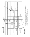
- FIG. 4A is a graph illustrating changes in enthalpy as a function of temperature according to an embodiment of the present invention.
- FIG. 4B is a graph illustrating changes in enthalpy as a function of temperature according to an embodiment of the present invention.
- FIG. 5 is a schematic diagram of a result of a heat exchanger network synthesis implementation for a simple problem according to an embodiment of the present invention
- FIG. 6 is a diagram illustrating an industrial process including process streams shown with respect to temperature step intervals used in targeting and utility selection according to an embodiment of the present invention
- FIGS. 7-9 are schematic diagrams of a result of a heat exchanger network synthesis implementation for the industrial process shown in FIG. 6 according to pinch design methods;
- FIG. 10 is a schematic diagram of a result of a heat exchanger network synthesis implementation for the industrial process shown in FIG. 6 according to an embodiment of the present invention.
- FIG. 11 is a schematic diagram of the result shown in FIG. 10 to include application of a low-quality utility according to an embodiment of the present invention
- FIG. 12 is a diagram illustrating an industrial process including process streams shown with respect to temperature step intervals used in targeting and utility selection according to an embodiment of the present invention
- FIG. 13 is a schematic diagram of a result of a heat exchanger network synthesis implementation for the industrial process shown in FIG. 12 according to a pinch design method;
- FIG. 14 is a schematic diagram of a result of a heat exchanger network synthesis implementation for the industrial process shown in FIG. 12 according to an embodiment of the present invention
- FIG. 15 is a diagram illustrating an industrial process including process streams shown with respect to temperature step intervals used in targeting and utility selection according to an embodiment of the present invention
- FIG. 16 is a schematic diagram of a result of a heat exchanger network synthesis implementation for the industrial process shown in FIG. 15 according to a pinch design method;
- FIG. 17 is a schematic diagram of a result of a heat exchanger network synthesis implementation for the industrial process shown in FIG. 15 according to an embodiment of the present invention.
- FIG. 18 is a diagram illustrating an industrial process including process streams shown with respect to temperature step intervals used in targeting and utility selection according to an embodiment of the present invention
- FIG. 19 is a schematic diagram of a result of a heat exchanger network synthesis implementation for the industrial process shown in FIG. 18 according to a pinch design method;
- FIG. 20 is a schematic diagram of a result of a heat exchanger network synthesis implementation for the industrial process shown in FIG. 18 according to an embodiment of the present invention
- FIG. 21 is a diagram illustrating an industrial process including process streams shown with respect to temperature step intervals used in targeting and utility selection according to an embodiment of the present invention
- FIG. 22 is a schematic diagram of a result of a heat exchanger network synthesis implementation for the industrial process shown in FIG. 21 according to a pinch design method;
- FIGS. 23-24 are schematic diagrams illustrating an application of streams splitting to synthesize a heat exchanger network for the industrial process shown in FIG. 21 according to an embodiment of the present invention
- FIG. 25 is a diagram illustrating an industrial process including process streams shown with respect to temperature step intervals used in targeting and utility selection according to an embodiment of the present invention
- FIG. 26 is a schematic diagram of a result of a heat exchanger network synthesis implementation for the industrial process shown in FIG. 25 according to a pinch design method;
- FIG. 27 is a schematic diagrams illustrating an application of streams splitting to synthesize a heat exchanger network for the industrial process shown in FIG. 25 according to an embodiment of the present invention
- FIG. 28 is a diagram illustrating a non-thermodynamically constrained industrial process including process streams shown with respect to temperature step intervals used in targeting and utility selection according to an embodiment of the present invention
- FIGS. 29-30 are schematic diagrams illustrating an application of homogeneous cold-cold stream matching to enhance synthesis of the heat exchanger network for the industrial process shown in FIG. 28 according to an embodiment of the present invention
- FIG. 31 is a diagram illustrating a non-thermodynamically constrained industrial process including process streams shown with respect to temperature step intervals used in targeting and utility selection according to an embodiment of the present invention
- FIG. 32 is a schematic diagram illustrating an application of homogeneous hot-hot stream matching to enhance synthesis of the heat exchanger network for the industrial process shown in FIG. 31 according to an embodiment of the present invention
- FIG. 33 is a diagram illustrating a non-thermodynamically constrained industrial process including process streams shown with respect to temperature step intervals used in targeting and utility selection according to an embodiment of the present invention
- FIG. 34 is a schematic diagram illustrating an application of hot-cold stream switching to enhance synthesis of the heat exchanger network for the industrial process shown in FIG. 33 according to an embodiment of the present invention
- FIG. 35 is a diagram illustrating a non-thermodynamically constrained industrial process including process streams shown with respect to temperature step intervals used in targeting and utility selection according to an embodiment of the present invention
- FIG. 36 is a schematic diagram illustrating an application of cold-hot stream switching to enhance synthesis of the heat exchanger network for the industrial process shown in FIG. 35 according to an embodiment of the present invention
- FIG. 37 is a schematic diagram of the heat exchanger network resulting from the industrial process shown in FIG. 35 prior to application of cold-hot stream switching according to an embodiment of the present invention
- FIG. 38 is a schematic diagram of the heat exchanger network resulting from industrial process shown in FIG. 35 after application of cold-hot stream switching shown in FIG. 36 according to an embodiment of the present invention.
- FIGS. 39-43 are schematic diagrams illustrating an application of successively lower minimum temperature approach values to the same industrial process to produce a series of heat exchanger networks each having a common process-to-process heat exchanger network structure according to an embodiment of the present invention.
- the total energy employed or consumed by the processes of a superstructure can be optimized to a global minimal level, for example, through careful placement and configuration of specific material streams with respect to one another and through application of a heat exchangers network (HEN) to allow waste heat recovery.
- HEN heat exchangers network
- heat exchangers network synthesis can be a major task. Streams having thermal energy already present that needs to be removed and streams that need to have heat added can be associated with one another to optimize the energy consumption of the process.
- careful selection of minimum temperature differences between hot streams and cold streams upon optimization can also result in huge savings in energy consumption.
- the state-of-art methods in commercial software and/or research papers describe two heat exchanger network design approaches: the pinch design method with its modifications, and the mathematical programming/optimization-based method that uses two main superstructure templates for automated synthesis or that employ optimization to only optimize an already given (initial) structure using the pinch design method directed to optimizing branching and heat exchanger duties.
- the most widely used software in industry produced through a process integration consortium is known as “Sprint” which includes application of the pinch design method followed by an optimization capability that optimizes the initial design (created by the pinch design method), through working on branches and duties of heat exchangers to achieve an “optimal” total cost network.
- This method has been accepted in the industrial community due to its non-black box approach whereby the process engineer is “in the loop” of the initial design of the heat exchangers network—i.e., the processing engineer can make design decisions that can change with the progress of the design.
- various embodiments of a method, system, and program product according to one or more embodiments of the present invention beneficially exhibit advanced capabilities over that of the pinch design method, while still keeping the process engineer “in the loop” of designing his/her heat exchanger network.
- the pinch design method can not handle, systematically, various cases that can result in certain possible network structures which can render better economics from the energy or/and capital points of view, various embodiments of the method, system, and program product provide just such capability.
- Such cases can include certain combinations of stream matching to account for non-thermodynamic constraint application situations, stream-specific minimum approach temperatures situations in which a hot stream is matched with a hot stream and/or a cold stream is matched with a cold stream, and partial stream conversion situation in which a hot stream is partially converted to cold stream and/or a cold stream is partially converted to hot stream, etc.
- various embodiments of a method, system, and program product can beneficially produce a heat exchanger network with a lesser number of heat exchanger units than the pinch design method for the threshold and near pinch problems due to a conceptual approach (limitation) of the pinch design method that results in a decomposition of the problem according to number of pinch and near pinch points.
- various embodiments of a method, system, and program product can produce heat exchanger networks with a lesser or equal number of heat exchanger units as compared with pinch design method for pinched problems due to the inefficiencies caused by the pinch philosophy of decomposition at each pinch point, and corresponding requirement, according to the pinch design methodology, to perform streams splitting at the pinch point to satisfy pinch design matching criteria, even in cases where such stream splitting would not otherwise be necessary.
- various embodiments of a method, system, and program product exhibit advanced capabilities over that of the mathematical programming/optimization-based method while still keeping the process engineer “in the loop” of designing his/her heat exchanger network.
- the mathematical programming/optimization-based method has been in academia since the late eighties, but is still not generally employed on large-scale industrial applications for several reasons.
- the computational requirements of such method can be excessive, and the solution, in general, can not consistently provide globality and frequently renders only a local mediocre solution due to, for example: the black box nature of the method, the assumptions regarding problem economics, the types of heat exchangers used in the network, the utilities types and temperatures that need to be known beforehand, the non-inclusive nature of the transshipment model for streams matching, and the superstructures that produce each heat exchanger network.
- various embodiments of a method, system; and program product can produce heat exchanger network designs having a cheaper life-cycle cost over those produced using state-of-the-art software due to the consideration of network retrofitability, systematically, during the design stage, which would not be available using the pinch design method or the mathematical programming/optimization-based method.
- the pinch design method does not, for example, have a systematic process to select an optimal set of stream specific minimum temperature and because its pinch design philosophy starts the design of the network after selecting an optimal network global minimum approach temperature, even by repeating a current sequential philosophy using the global minimum temperature approach, the resulting new network structure would not be expected to consistently resemble the previous network structure, in class.
- the mathematical programming/optimization-based method does not, for example, include a model for addressing the “retrofitability” of the design produced using any existing superstructure for the future changes in energy cost, like the pinch design method, the mathematical programming/optimization-based method also lacks the notion of designing systems that exhibit minimum life-cycle cost, such would need to be developed to address the heat exchanger network “retrofitability” notion.
- FIG. 1 illustrates an exemplary system 30 to synthesize a grass-roots heat exchanger network for at least one, but more typically, a substantial number of hot process streams to be cooled and at least one, but more typically, a substantial number of cold process streams to be heated according to one or more utilities targets.
- the system 30 can include a heat exchanger network synthesizing computer 31 having a processor 33 , memory 35 coupled to the processor 33 to store software and database records therein, and a user interface 37 that can include a graphical display 39 for displaying graphical images, and a user input device 41 as known to those skilled in the art, to provide a user access to manipulate the software and database records.
- the computer 31 can be in the form of a personal computer or in the form of a server or multiple servers serving multiple user interfaces 37 . Accordingly, the user interface 37 can be either directly connected to the computer 31 or through a network 38 as known to those skilled in the art.
- the system 30 can also include one or more tables and/or databases 43 stored in memory (internal or external) that is operably coupled to the heat exchanger network synthesizing computer 31 , as would be understood by those skilled in the art.
- the one or more databases 43 can include one or more discrete values or sets/ranges of values for various operational attributes for each of the hot process streams and one or more discrete values or sets/ranges of values for various operational attributes for each of the cold process streams.
- Such operational attributes can include, for example, a discrete supply temperature (Ts) and/or a lower and an upper boundary value for the supply temperature of each of the hot process streams and each of the cold process streams, a discrete target temperature (Tt) and/or a lower and an upper boundary value for the target temperature of each of the hot process streams and each of the cold process streams, and a discrete heat capacity flow rate (FCp) and/or a lower and an upper boundary value for the heat capacity flow rate of each of the hot process streams and each of the cold process streams, and a corresponding discrete enthalpy value or a corresponding minimum and maximum enthalpy value if any range or set data was provided/received for one or more of the other operational attributes.
- Ts discrete supply temperature
- Tt discrete target temperature
- FCp discrete heat capacity flow rate
- the one or more tables and/or databases 43 can also include a constrained stream list or table as would be understood by one of ordinary skill in the art, including an identification of any non-thermodynamically constrained process streams constrained from matching at least one other process stream due to a non-thermodynamic constraint, such as, for example, an indication that hot stream # 1 of a particular process is forbidden from matching with cold stream # 2 , etc.
- the one or more tables and/or databases 43 can also include a determined or assigned stream-specific minimum temperature approach value ( ⁇ T min i ) for each separate one of the plurality of hot process streams and/or cold streams, a determined or assigned dual stream-specific minimum temperature approach value ( ⁇ T min i ) for each separate one of the hot process streams, and/or a determined or assigned set of range of stream-specific minimum temperature approach values ( ⁇ T min i ⁇ ), e.g., a minimum or maximum or range interval, for each separate one of the hot process streams.
- ⁇ T min i stream-specific minimum temperature approach value
- ⁇ T min i ⁇ e.g., a minimum or maximum or range interval
- the dual-stream stream-specific minimum temperature approach concept is the case where a hot stream can have two stream-specific minimum temperature approach values provided for the sake of allowing a trade off between the quantity of total energy saved and the quality of stream-specific energy preserved, without regard to heat exchanger area or fixed cost, which is unavailable to a user according to the pinch design method.
- the dual-stream stream-specific minimum temperature approach concept should not be confused with the dual temperature approach design method described in the literature which describes two approach temperatures: a global minimum temperature approach value for network heat recovery and another for a specific heat exchanger used to violate the global minimum temperature approach under certain circumstances for the sake of saving capital, and not for preserving stream quality (temperature).
- the system 30 can also include heat exchanger network synthesizing program product 51 stored in memory 35 of the heat exchanger network synthesizing computer 31 and adapted to synthesize a heat exchanger network that in certain situations sharply satisfies, or at least substantially satisfies, the utilities desired consumption within its defined bounds with at least the same, but more typically, a lesser number of heat exchanger units as compared with that produced using the pinch design method, using advanced matching solutions, systematically; and that in other situations will achieve both a lesser number of units and less utilities consumption, as well as producing a network that is easily retrofitable in the future to accommodate changes in energy prices for a given list of process streams to be either cooled or heated according to their respective heat capacity flow rates, supply and target temperatures, stream-specific minimum temperature approaches and/or dual stream-specific minimum temperature approaches and according to any utilities targets that need to be satisfied or substantially satisfied through bounded targets, and for a given list of streams matching constraints.
- the program product 51 can be employed to synthesize a heat exchanger network (preferably one that has a topology that is easily retrofitable-in-future) for a process or cluster of processes that achieves: at least one utility objective which exactly satisfies certain heating and cooling utilities loads; at least one objective using a fewer number of heat exchanger units; at least one objective which satisfies, in bounded range, certain heating and cooling utilities; at least one objective using either a heating or a cooling utility; at least one objective using less hot utility consumption; at least one objective using less cold utility consumption; at least one objective using a lesser number of hot utilities types; at least one objective using a lesser number of cold utilities types; at least one objective with less degradation in the process source region; and/or at least one objective with better utilization of the process sink region, responsive to receiving set of process and/or utility systems attribute values for the major resource stream used by the process or cluster of processes, receiving at least one set of stream-specific minimum
- the program product 51 can provide a systematic technique adapted to execute the additional preliminary steps of: identifying operational attributes of process streams used within the process in a heat exchanger network which affect the multiple utility consumption of the process or the number of heat exchangers units used in the process or both and/or any other objective of the ones described above, indicating the specific attribute value or values from the range or ranges supplied by the user (in the beginning or even decided during the implementation of the procedures) that result in the new utility consumption value or values calculated, and can provide for synthesizing the heat exchanger network responsive thereto to achieve one or more of the associated objectives identified above.
- the heat exchanger network synthesizing program product 51 can be in the form of microcode, programs, routines, and symbolic languages that provide a specific set or sets of ordered operations that control the functioning of the hardware and direct its operation, as known and understood by those skilled in the art.
- the heat exchanger network synthesizing program product 51 need not reside in its entirety in volatile memory, but can be selectively loaded, as necessary, according to various methodologies as known and understood by those skilled in the art.
- Step # 0 Treat the problem as one problem without decomposition.
- Step # 1 Receive attribute data for hot and cold streams of the process or processes.
- Step # 2 Generate temperature intervals and apply specific minimum temperature approach values.
- Step # 3 Match streams at each temperature interval for all types of problems moving from top-to-bottom (highest to lowest). Match streams that can cancel each other or one of them with minimum quality degradation to the other. Match streams with maximum overlap or with equal or close to equal heat capacity flow rates (FCps). Match streams having high FCps and high overall heat transfer coefficients (Us) with streams having low FCps with low Us. Employ stream switching/partial conversion, homogeneous matching, or buffers (if feasible) to overcome non-thermodynamic constraints.
- Step # 4 Target for utilities as guidance and balance loads using utilities during step down through the temperature intervals.
- Step # 5 Split streams as necessary to reach the desired utilities loads and/or qualities.
- Step # 6 Determine an initial heat exchanger network design.
- Step # 7 Remove redundant process-to-process heat exchanger units.
- Step # 8 Merge same stream utility heat exchanger units.
- Step # 9 Determine the final heat exchanger network design.
- Step 1 includes receiving input data, for example, entered by a user or stored in the database 43 .
- the data can include, for example, a discrete supply temperature (Ts) and/or a lower and an upper boundary value for a supply temperature interval (Ts[L:U]) of each of the hot process streams and each of the cold process streams, a discrete target temperature (Tt) and/or a lower and an upper boundary value for a target temperature interval (Tt[L:U]) for each of the hot process streams and each of the cold process streams, and a discrete heat capacity flow rate (FCp) and/or a lower and an upper boundary value for the heat capacity flow rate interval (FCp[L:U]) for each of the hot process streams and each of the cold process streams, and a corresponding discrete enthalpy value or a corresponding minimum and maximum enthalpy value if any range or set data was provided for one or more of the other operational attributes.
- Ts discrete supply temperature
- Ts[L:U]
- supply temperature (Ts) and the target temperature (Tt) can be in the form of actual supply and target temperatures
- the supply temperature (Ts) and the target temperature (Tt) can be real values minus a user-selected minimum.
- the data can also include a discrete and/or dual stream specific minimum temperature approach values ( ⁇ T min i ) for each the hot process streams, and a list of one or more constrained process streams constrained from matching at least one other resource stream due to a non-thermodynamic constraint (e.g., a list forbidden matches).
- Step 2 includes generating temperature intervals 100 (see e.g., FIG. 2 ) and applying specific minimum temperature approach values ( ⁇ T min i ) to each of the hot streams.
- FIG. 2 provides an example of a graph illustrating a simple example of an industrial process overlaid upon successive temperature intervals 100 generated therefor according to an embodiment of the present invention, that includes four separate and distinct process streams H 1 , H 2 , C 1 , C 2 .
- Process streams H 1 and H 2 are hot streams, whereas streams C 1 and C 2 are cold streams.
- separate operational attributes for each process stream are modeled.
- Ts supply temperature
- Tt target temperature
- FCp heat capacity flow rate
- the cold streams C 1 and C 2 are first drawn or otherwise formulated, at least conceptually, from their start temperatures to their target temperatures using their actual data, and each hot stream H 1 and H 2 is then shifted down by its respective stream-specific minimum temperature approach values ( ⁇ T min i ) (e.g., individual stream-specific minimum approach temperature or dual stream-specific minimum approach temperatures) to embed the separate ⁇ T min i values in the hot streams H 1 and H 2 .
- ⁇ T min i stream-specific minimum temperature approach values
- Lines are drawn or otherwise formulated, at least conceptually, on the start and end of each stream to define the process stream arrow 101 , 103 , 105 , 107 .
- the temperature intervals 100 are defined as shown in FIG.
- energy targets Qh, Qc are calculated along with the process bifurcation temperature(s) to facilitate the heat exchanger network synthesis task.
- the process bifurcation temperature (PBT) shown at 111 is the point at which the process is transformed from being a heat sink to becoming a heat source.
- PBT process bifurcation temperature
- the term “conceptually” has been used in this paragraph to denote that when the step(s) are performed on a computer, the parameters for each stream are calculated, but not necessarily graphically displayed.
- Step 3 includes matching streams at each temperature interval 101 for all types of problems moving from top-to-bottom (highest to lowest), and Step 4 includes targeting for utilities as guidance, and balancing loads using utilities during step down through the temperature intervals.
- FIGS. 3-4B provide a background framework for performing the utilities consumption calculations. Particularly, FIG. 3 illustrates changes in enthalpy at each of the temperature step intervals.
- FIGS. 4A-4B illustrate modified grand composite curves modified to provide various visual enhancements. That is, FIG. 4A , for example, uses a real temperature scale and not a shifted temperature scale as described in literature.
- FIG. 4B illustrates the curve shown in FIG.
- each heating duty (Qh) shifted by a “user-selected/desired” hot utility-process minimum temperature approach value (Thu) for each of the temperature step intervals.
- the figures also beneficially depict temperature on the horizontal scale and enthalpy at the vertical scale. Having temperature on the horizontal “X” axis, rather than on the vertical axis as described in literature, enables a graphical estimation of the increase or decrease in the “area under the curve” due to the selection of utilities and/or changing process conditions which is directly proportional to amount of work needed by the process and amount of work that can be extracted from the process, as well as amount of work that might be lost by the process under the given conditions. As shown in FIG.
- FIG. 5 shows a schematic of a result of a heat exchanger network synthesis implementation for the simple problem.
- Hot stream for example, can be matched with cold streams, cold utilities, and/or another hot stream, which can be according to various hot stream connections including, for example, parallel, series, parallel-series, series-parallel, and by-pass (of one or more units of any match) connections.
- hot stream connections including, for example, parallel, series, parallel-series, series-parallel, and by-pass (of one or more units of any match) connections.
- matching is performed between hot streams and utilities with cold streams starting at the highest temperature interval 100 on the temperature scale and proceeds from that top to the bottom.
- This top-to-bottom matching methodology is in complete contrast to the conventional pinch design method whereby the matching is carried out at the pinch point (typically located at a medial location on the temperature scale) and then moves up on the temperature scale above the pinch point to complete an above-pinch sub-problem and then starts again at the pinch point and moves down the temperature scale below the pinch point to complete a below-pinch sub-problem.
- the top-to-bottom approach beneficially facilitates matching streams at the same temperature interval where the temperature approach between the hot and cold streams are at a minimum, and where the balance/difference between the supply of the hot and the demand of the cold can be compensated by a utility with the lowest possible supply temperature. Such approach can substantially minimize the energy “quality” loss or degradation in energy quality in the hot process streams and/or hot utilities.
- the step of matching can also include matching streams that can either cancel each other or that provides one of them with minimum quality degradation when matched to the other; matching streams with maximum overlap or with equal or close to equal heat capacity flow rates (FCps); matching streams having high FCps and high overall heat transfer coefficients (Us) with streams having low FCps with low heat transfer coefficients; and/or employing stream switching/partial conversion, homogeneous matching, or the inclusion of buffers (if feasible) to overcome non-thermodynamic constraints.
- FIGS. 6 through 27 provide six simple comparative examples illustrating how using advanced matching solutions can yield a lesser number of heat exchanger units 131 as compared with that produced using, for example, the pinch design method followed by the optimization option, in cases that may be expected to be encountered in industry.
- FIG. 6 provides a graph illustrating a simple example of an industrial process to be used in a comparative analysis, overlaid upon successive temperature intervals 100 generated therefor.
- the illustrated industrial process incorporates three separate and distinct process streams H 1 , C 1 , C 2 , having only discrete values for the supply temperature, the target temperature, and the heat capacity flow rate, and with a minimum temperature approach value ( ⁇ T min ) of 10° F. embedded in the hot stream H 1 , to facilitate comparison between: the results of application of the pinch design method yielding a network design having nine heat exchangers (see FIG.
- various embodiments of the present invention can treat the problem as a single problem, without decomposition, which can result in a lesser number of heat exchanger units 131 than possible using the pinch design method, which decomposes the problem into two problems, or sometimes more than two problems in the case of multiple process pinches or a near pinch situation as in FIG. 6 where we have a near pinch situation.
- the pinch design method calls for dividing the problem to three sub-problems: one between the pinch and near pinch temperatures (150-200 degrees), one above 200 degrees, and one below 150 degrees.
- the pinch design method with software optimization states that the minimum number (or U_min.) equals the sum of the total number of streams (including utility streams) minus one. Accordingly, the sub-problem between the pinch and near pinch points (150-200 degrees), which contains two process streams and one utility stream, requires at least two heat exchanger units 131 .
- the sub-problem above 200 degrees, which contains three process streams and one utility stream, requires at least three heat exchanger units 131 .
- the sub-problem below 200 degrees, which contains one process stream and one utility stream, requires at least one heat exchanger unit 131 . That is, total minimum number of heat exchanger units 131 needed will be at least six heat exchanger units 131 using pinch design method rules.
- the best design capable of resulting from this type of network design methodology applied to a problem such as, for example, that shown in FIG. 6 will always render a larger number of heat exchanger units 131 than that provided according to the exemplary embodiment of the present invention (see, e.g., FIG. 9 ), even in situations where the between pinch and near pinch area does not require use of a utility stream.
- decomposing the problem at the pinch and beginning the matching process at the pinch leads to streams split with no reason other than to satisfy the criteria of matching at the pinch, resulting in an artificial constraint solved by unnecessarily splitting streams, and thus, producing a network with a greater number of heat exchanger units 131 than would otherwise be necessary.
- the pinch design method treats threshold problems (problems that only need cooling utility or only need heating utility), which do not have a pinch/constraint, as a pinched problem in order to generalize the pinch design method for handling all types of problems. Doing so, however, disadvantageously creates an artificially constrained situation, which necessitates the splitting of streams at the factious pinch to satisfy the matching criteria at the pinch according to the pinch design method rules. Beneficially, various embodiments in the present invention do not have such limitation, and thus, in such cases should always render a smaller number of heat exchanger units 131 than that provided according to the pinch design method.
- hot stream H 1 having a heat capacity flow rate FCp of 1 mmBTU/h/° F. is matched at the highest temperature interval with C 2 also having a heat capacity flow rate FCp of 1 mmBTU/h/° F., which provides a maximum overlap, and which resultantly completely cancels C 2 .
- FIG. 11 provides a modification of the design shown in FIG. 10 , according to an embodiment of the present invention.
- cold stream C 1 is virtually split to form C 11 and C 12 and a low quality utility is utilized at 152 in conjunction with a high quality utility utilized at 151 to heat cold stream C 12 , to thereby minimize overall utilities cost, but at the expense of one more heat exchanger.
- the total number of heat exchangers (five) is still less than the pinch design method network followed by software optimization option (six), by one heat exchanger.
- FIG. 12 illustrates another simple example of an industrial process to be used in a comparative analysis, overlaid upon successive temperature intervals 100 generated therefor.
- the illustrated industrial process incorporates four separate and distinct process streams H 1 , H 2 , C 1 , C 2 , having only discrete values for the supply temperature, target temperature, and heat capacity flow rate, and with a minimum temperature approach value ( ⁇ T min i ) of 10° C. embedded in each of the hot streams H 1 , H 2 , to facilitate a comparison between: the results of application of the pinch design method followed by the software optimization option yielding a network design having eight heat exchangers (see FIG. 13 ); and that produced according to an embodiment of the present invention yielding a network design having only five heat exchangers ( FIG. 14 ).
- hot stream H 1 is matched at the highest temperature interval with C 1 and both H 1 and H 2 are matched to provide a maximum overlap with C 1 , which collectively results in a lesser number of required heat exchanger units for the same total heating and cooling duty.
- FIG. 15 illustrates another simple example of an industrial process overlaid upon successive temperature intervals 100 generated therefor, which provides an example of a threshold problem (cooling only).
- the illustrated industrial process incorporates four separate and distinct process streams H 1 , H 2 , C 1 , C 2 , having only discrete values for the supply temperature, target temperature, and heat capacity flow rate, and with a minimum temperature approach value ( ⁇ T min i ) of 10° K. embedded in each of the hot streams H 1 , H 2 , to facilitate a comparison between: the results of application of the pinch design method followed by the software optimization option yielding a network design having four heat exchangers (see FIG. 16 ); and that produced according to an embodiment of the present invention yielding a network design having only three heat exchangers ( FIG.
- hot stream H 1 is matched at the highest temperature interval with C 2 having a same heat capacity flow rate and completely canceling C 2
- H 2 is matched at the highest temperature interval with C 1 to provide a maximum overlap with C 1 and to completely cancel C 1 , which results in a lesser number of required heat exchanger units for the same total cooling duty.
- FIG. 18 illustrates another simple example of an industrial process overlaid upon successive temperature intervals 100 generated therefor, which provides an example of a threshold problem (heating only).
- the illustrated industrial process incorporates four separate and distinct process streams H 1 , H 2 , C 1 , C 2 , having only discrete values for the supply temperature, target temperature, and heat capacity flow rate, and with a minimum temperature approach value ( ⁇ T min i ) of 10° K. embedded in each of the hot streams H 1 , H 2 , to facilitate a comparison between: the results of application of the pinch design method followed by the software optimization option yielding a network design having six heat exchangers (see FIG. 19 ); and that produced according to an embodiment of the present invention yielding a network design having only five heat exchangers ( FIG.
- hot stream H 1 is matched with C 1 having a same heat capacity flow rate and complete overlap resulting in a complete cancellation of H 1
- H 2 is matched at the highest temperature interval with C 2 to provide a maximum overlap with C 2 and at the lowest temperature interval with C 1 to maximize heat exchange (enhance utilization), which results in a lesser number of required heat exchanger units for the same total heating load/duty.
- Step 5 includes splitting streams as necessary to reach the desired utilities loads and/or qualities.
- Stream splitting can be conducted, for example, upon user request/selection, e.g., to reduce energy quality degradation due to matching a hot stream at a certain temperature interval at the process sink region with cold streams at lower temperature intervals.
- This technique is in contrast to the pinch design method, whereby splitting is conducted at the pinch point merely to satisfy problem feasibility issues, i.e., matching criteria at the pinch, or above and below the pinch regions, which is a major cause in producing network designs with an excessive number of heat exchangers.
- FIGS. 21-24 and 25 - 27 provide two separate problems and comparative network synthesis to include illustrations of streams splitting according to an embodiment of the present invention.
- the first stream splitting example provides a simple industrial process overlaid upon successive temperature intervals 100 generated therefor, that includes four separate and distinct process streams H 1 , H 2 , C 1 , C 2 , having only discrete values for the supply temperature, target temperature, and heat capacity flow rate, and with a minimum temperature approach value ( ⁇ T min i ) of 10° K. embedded in each of the hot streams H 1 , H 2 , to facilitate a comparison between: the results of application of the pinch design method followed by the software optimization option yielding a network design having ten heat exchangers (see FIG. 22 ); and that produced according to an embodiment of the present invention yielding a network design having only seven heat exchangers ( FIGS. 23-24 ).
- hot stream H 2 having a heat capacity flow rate FCp of 7 kW/° K. ( FIG. 22 ) is split into three separate hot streams H 21 , H 22 , H 23 , having heat capacity flow rates of 3 kW/° K., 2 kW/° K., and 2 kW/° K., and cold stream C 2 having a heat capacity flow rate FCp of 17 kW/° K.
- FIG. 22 is split into two separate cold streams C 21 , C 22 , having heat capacity flow rates of 2 kW/° K. and 15 kW/° K.
- the stream splitting allows: matching H 1 with a stream C 22 having an equal heat capacity flow rate, a complete canceling out between H 22 and C 21 , and a maximum overlap with the equal heat capacity flow rate between H 23 and C 1 (see FIG. 24 ).
- the second stream splitting example provides another simple industrial process overlaid upon successive temperature intervals 100 generated therefor, that includes four separate and distinct process streams H 1 , H 2 , C 1 , C 2 , having only discrete values for the supply temperature, target temperature, and heat capacity flow rate, and with a minimum temperature approach value ( ⁇ T min i ) of 10° K. embedded in each of the hot streams H 1 , H 2 , to facilitate a comparison between: the results of application of the pinch design method followed by the software optimization option yielding a network design having seven heat exchangers (see FIG. 26 ); and that produced according to an embodiment of the present invention yielding a network design having only five heat exchangers ( FIG. 27 ).
- hot stream H 1 having a heat capacity flow rate FCp of 3 kW/° K. ( FIG. 25 ) is split into two separate hot streams H 11 , H 12 , having heat capacity flow rates of 1.846 kW/° K. and 1.154 kW/° K.
- the stream splitting allows matching C 2 with a stream H 11 at the highest temperature interval which can completely cancel C 2 , and matching C 1 with a stream H 12 at the highest temperature interval which has a close to equal heat capacity flow rate and can substantially cancel C 1 .
- Various embodiments of the program product 51 include, for example, instructions to convert a stream from having a mono-matching capability to that having a bi-matching capability according to the following procedures, which can be triggered upon having a forbidden match case.
- FIGS. 28-38 provide two illustrative examples employing homogeneous (hot-to-hot, cold-to-cold) matching and two illustrative examples employing stream designation switching (e.g., changing or otherwise designating a certain stream attribute(s) of a hot/cold process stream to be changed or otherwise reassigned from a certain desired value to another one, changing or otherwise assigning the designation of a portion of the hot/cold process stream to that of a cold/hot stream, and changing the stream attribute value back to the initially desired value to achieve one of the target values, for example), to overcome certain process constraints.
- stream designation switching e.g., changing or otherwise designating a certain stream attribute(s) of a hot/cold process stream to be changed or otherwise reassigned from a certain desired value to another one, changing or otherwise assigning the designation of a portion of the hot/cold process stream to that of a cold/hot stream, and changing the stream attribute value back to the initially desired value to achieve one of the target values,
- FIGS. 28-30 introduce a scenario providing an opportunity for a first cold stream C 1 to be heated up by a second cold stream C 2 to recover hot utility, as C 1 is constrained from matching with H 1 .
- FIG. 28 illustrates a simple non-thermodynamically constrained industrial process overlaid upon successive temperature intervals 100 generated therefor.
- the illustrated industrial process incorporates three separate and distinct process streams H 1 , C 1 , C 2 , having only discrete values for the supply temperature, target temperature, and heat capacity flow rate, and with a minimum temperature approach value ( ⁇ T min ) of 10° K. embedded in hot stream H 1 .
- the industrial process has a non-thermodynamic constraint whereby H 1 is forbidden from being matched with C 1 .
- the hot utility duty would be 600 kW and the cold utility duty would be 50 kW, as hot stream H 1 would only be matched with cold stream C 2 .
- cold stream C 2 having a higher supply temperature than that of C 1 , can first be cooled to a medial point therebetween and then later heated to the desired target temperature.
- cold stream C 2 upon employing the homogeneous match between cold stream C 1 and cold stream C 2 , cold stream C 2 is cooled below the 250° K. supply temperature to the maximum extent possible by C 1 , which in this example would be 205° K. using a cold-cold minimum temperature approach value ( ⁇ T min ) of 10° K.
- ⁇ T min cold-cold minimum temperature approach value
- cold stream C 2 This results in a requirement whereby cold stream C 2 will require more heating utilities to reach its target temperature than would have been necessary according to its original situation.
- the excessively cooled cold stream, here cold stream C 2 can then be heterogeneously matched with hot stream H 1 .
- the ⁇ T min used during the homogeneous and heterogeneous matching steps will have an effect on the outcome. That is, in the homogeneous matching step, cold stream C 2 is cooled to a temperature of 205° K., which is a ⁇ T min desired value above the C 1 supply temperature, creating a new C 2 supply temperature that is lower than the original. In the heterogeneous match step, such new supply temperature will be the one used in matching C 2 with H 1 to reduce the hot utility needs.
- C 2 can be split to form C 21 and C 22 , each having a starting temperature of 205° K., and each having heat capacity flow rates of 1 kW/° K.
- the stream splitting allows matching C 21 with a stream H 1 at the highest temperature interval which has an equal heat capacity flow rate and can substantially cancel H 1 (i.e., only the portion below the 205° K. line still needs be cooled by a utility).
- This configuration reduces hot utility requirements from 600 kW to 555 kW and cold utility requirements from 50 kW to 5 kW.
- FIG. 31 illustrates another simple non-thermodynamically constrained industrial process overlaid upon successive temperature intervals 100 generated therefor.
- the illustrated industrial process incorporates three separate and distinct process streams H 1 , H 2 , C 1 , each having only discrete values for the supply temperature, target temperature, and heat capacity flow rate, and with different minimum temperature approach values ( ⁇ T min i ) of 20° K. and 10° K. embedded in hot streams H 1 , H 2 , respectively.
- the industrial process has a non-thermodynamic constraint whereby H 1 is forbidden from being matched with C 1 .
- the hot utility duty would be 300 kW and the cold utility duty would be 490 kW, as only hot stream H 2 , having a minimal overlap, would be matched with cold stream C 1 .
- hot stream H 2 having a lower supply temperature than that of H 1 , can first be heated to a medial point therebetween and then later cooled to the desired target temperature. Specifically, hot stream H 2 is heated above the 300° K. supply temperature to the maximum extent possible by H 1 , which, in this example, would be 425° K. using a hot-hot ⁇ T min of 10° K. (equal to the difference between ⁇ T min H1 and ⁇ T min H2 ).
- H 2 having a heat capacity flow rate of 2 kW/° K., and now having a starting temperature of 425° K., is matched with C 1 also having a heat capacity flow rate of 2 kW/° K., and now having a substantial overlap with H 2 .
- This configuration reduces hot utility requirements from 300 kW to 50 kW and cold utility requirements from 490 kW to 240 kW, using the same total number of heat exchangers.
- FIG. 33 illustrates another simple non-thermodynamically constrained industrial process overlaid upon successive temperature intervals 100 generated therefor.
- the illustrated industrial process incorporates three separate and distinct process streams H 1 , H 2 , C 1 , each having only discrete values for the supply temperature, target temperature, and heat capacity flow rate; and with different minimum temperature approach values ( ⁇ T min i ) embedded in hot streams H 1 , H 2 , respectively.
- the industrial process has a non-thermodynamic constraint whereby H 2 is forbidden from being matched with C 1 .
- the hot utility duty would be 150 kW and the cold utility duty would be 500 kW, as only hot stream H 1 would be matched with cold stream C 1 .
- hot stream H 1 having a higher target temperature than that of H 2 , can first be cooled to a point below its target temperature and then later heated to the desired target temperature. Specifically, as shown at 171 , hot stream H 1 is cooled below the 300° K. target temperature to the maximum extent possible by C 1 , which in this example would be 150° K. As further illustrated, the below-target portion of H 1 (H 1 _conv) taking the role of a cold stream having a starting temperature of 160° K. (using a hot-hot ⁇ T min of 10° K.) shown at 172 is matched with H 2 .
- This configuration uses an extra 150 kW of energy to completely cancel out C 1 and then regains the energy from H 2 , thus reducing the hot utility requirements from 150 kW to 0 kW and cold utility requirements from 500 kW to 350 kW, using the same number of heat exchangers.
- FIG. 35 illustrates another simple non-thermodynamically constrained industrial process overlaid upon successive temperature intervals 100 generated therefor.
- the illustrated industrial process incorporates three separate and distinct process streams H 1 , C 1 , C 2 , each having only discrete values for the supply temperature, target temperature, and heat capacity flow rate, and with a minimum temperature approach value ( ⁇ T min ) of 10° C. embedded in hot stream H 1 .
- the industrial process has a non-thermodynamic constraint whereby H 1 is forbidden from being matched with C 2 .
- the hot utility duty would be 700 kW and the cold utility duty would be 200 kW, as hot stream H 1 would be matched with only cold stream C 1 .
- FIG. 37 provides a depiction illustrating a simple heat exchanger network resulting from the configuration shown in FIG. 35 prior to application of the “cold-to-hot” stream switching matching solution.
- cold stream C 1 having a lower target temperature than that of C 2 , can first be heated to a point above its target temperature and then later cooled to the desired target temperature. Specifically, cold stream C 1 is heated above the 350° C. target temperature to the maximum extent possible by H 1 as shown at 181 , which in this example would be 550° C. As further illustrated, the above-target portion of C 1 (C 1 _conv) taking the role of a hot stream as shown at 182 having a starting temperature of 540° C. (using a cold-cold ⁇ T min of 10° C.) is matched with C 2 .
- FIG. 38 provides a depiction illustrating a simple heat exchanger network resulting from the configuration shown in FIG. 36 .
- a subroutine in the form of a feasibility test is run to determine whether homogeneous matching, stream switching, or a combination thereof, will yield better results.
- a hot-to-hot homogeneous match between hot streams H 1 and H 2 of the simple non-thermodynamically constrained industrial process shown in FIG. 33 would not be the desired solution as the hot stream H 2 having the non-thermodynamic constraint with the sole cold stream C 1 has a lower supply temperature than that of hot stream H 1 .
- a cold-to-cold homogeneous match between cold streams C 1 and C 2 of the simple non-thermodynamically constrained industrial process shown in FIG. 35 would not be the desired solution as the cold stream C 2 having the non-thermodynamic constraint with the sole hot stream H 1 has the same supply temperature as that of cold stream C 1 .
- homogeneous matching and stream switching are provided as an improvement over the use of buffer streams as understood by the skilled in the art, positioned between constrained process streams.
- Inclusion of buffer streams, if feasible, to overcome non-thermodynamic constraints is still within the scope of various embodiments of the present invention, depending upon its availability and the capital cost impact of its associated components.
- various embodiments of the present invention can also include the step of analyzing the feasibility of and capital cost related to employing buffer streams to thereby determine the overall effectiveness of the various methodologies of overcoming the non-thermodynamic constraints.
- Application of homogeneous matching and stream type switching provides the most cost-effective methodology along a continuum of a trade-off between resource preservation and capital investment.
- buffer streams are not as mechanically simple or inexpensive as is the case in homogenous matching and/or switching the type of stream in a certain range according to various embodiments of the present invention, which generally only requires adding new heat exchangers. Rather, employment of buffer streams entails building and maintaining the new system infrastructure (water, hot oil, steam and so on). Beneficially, using the above described homogeneous matching and/or stream type switching technique provides substantial capital cost savings if application thereof renders sufficient heat recovery. Notably, even if the decision is made to employ a buffer stream rather than homogeneous matching or stream type switching, employment of only one buffer system may not be sufficient to accomplish the required goals. Often, multiple buffer systems may be needed.
- the network designer may need to build both a steam generation system (waste heat boiler and its associated components) and a chilled water system.
- a steam generation system waste heat boiler and its associated components
- a chilled water system unless the amount of additional waste heat recovery that can be extracted for heating capacity and/or cooling capacity using one or more buffer systems to overcome the situation of forbidden matches are sufficient to justify the systems capital cost; or unless the required materials to build the buffer streams are already in place, the above described homogeneous matching and/or stream type switching techniques according to various embodiments of the present invention, will generally provide more cost effective solutions to such types of situations of stream forbidden matches.
- Step 6 includes completing or continued processing and/or graphically displaying to a decision maker, for example, an initial heat exchanger network design provided as a result of the stream matching and stream splitting steps.
- the initial heat exchanger network and/or other statistics can be displayed on a graphical user interface such as graphical user interface 39 or on a separate remote computer/computer display (not shown) in communication with network 38 (see FIG. 1 ).
- Step 7 includes removing (merging) any redundant process-to-process heat exchanger units. That is, any heat exchanger units extending between the same two process streams can be consolidated into a single heat exchanger, if feasible, to reduce the heat exchanger requirements.
- Step 8 Similar to Step 7, Step 8 includes merging any heat exchanger units extending between the same process and utility streams into a single heat exchanger, if feasible, to reduce the heat exchanger requirements.
- Step 9 includes determining the final heat exchanger network design based upon the initial design and based upon the consolidating/merging process.
- Various embodiments of the present invention provide systems, program product, and methods of synthesizing an, e.g., grass-roots, heat exchanger network for an industrial process including multiple hot process streams to be cooled and multiple cold process streams to be heated, and various hot and/or cold utilities to supplement the waste heat recovery system.
- an, e.g., grass-roots, heat exchanger network for an industrial process including multiple hot process streams to be cooled and multiple cold process streams to be heated, and various hot and/or cold utilities to supplement the waste heat recovery system.
- Step # 1 Start heat exchanger network (HEN) synthesis using high minimum temperature approach value or set of values.
- Step # 2 Synthesize several HENs at sequentially lower minimum temperature approach values using a systematic method.
- Step # 3 Produce HENs that are all exhibiting the same structure/topology and differ only in load allocation (heat exchanger duty or heat transfer between streams) and the possibility of adding additional heat exchanger units and/or bypassing excess heat exchanger units partially and/or completely.
- Step # 4 Select network that satisfies current economic criteria and keep other designs for future retrofit upon the change in the trade-off between energy cost and capital cost.
- Step # 5 Reserve in the plant layout sufficient free space for the specific heat exchangers that will require extra surface area in the future due to anticipated possible increased load.
- Steps 1-3 The steps of synthesizing a grassroots heat exchanger network for future retrofit by synthesizing several grass-roots heat exchanger network designs at sequentially lower minimum temperature approach values ⁇ T min i beginning at a high (“maximum”) minimum temperature approach value (or set of values) using a systematic method, in accordance with steps 1-3, are shown, for example, in FIGS. 39-43 , according to an example of an embodiment of the present invention. That is, the exemplary implementation shown in FIGS.
- 39-43 illustrates an example of a step-by-step synthesis of a grassroots-design-for-future-retrofit to include an illustration of how application of sets of successively different (e.g, lower) stream-specific minimum temperature approach values ⁇ T min i for each hot process stream, beginning, for example, at the highest minimum temperature approach values, followed by successively lower minimum temperature approach values, can yield a series of heat exchanger network configurations having common network structures, but with the possibility of having successively fewer numbers of heat exchanger units, which can be used to facilitate construction on a heat exchanger network that has a topology that is easily retrofittable based on possible future differing load requirements.
- the exemplary configuration features beginning at a maximum temperature approach value or set of values, embodiments where a minimum temperature approach value or values are used to begin the analysis are within the scope of the present invention.
- FIG. 39 provides another simple example of an industrial process overlaid upon successive temperature intervals 100 generated therefor, that includes four separate and distinct process streams H 1 , H 2 , C 1 , C 2 , with hot stream H 1 having an actual supply temperature of 130° K. (shown as 105° K.
- both hot streams H 1 , H 2 are initially assigned a same minimum temperature approach value ( ⁇ T min i ) of 25° K., for simplicity, which are embedded in each of the hot streams' temperature intervals 100 —i.e., the supply and target temperatures for hot streams H 1 and H 2 are each shifted down by an amount equal to their individual minimum temperature approach values ( ⁇ T min i ), which in FIG. 39 is 25° K. for both.
- the ⁇ T min H1 value of 25° K. is deducted from the hot stream supply temperature of 130° K. for H 1 and the target temperature of 40° K. for H 1 and the ⁇ T min H2 value of 25° K. is deducted from hot stream supply temperature of 180° K. for H 2 and the target temperature of 80° K. for H 2 to produce the values at the tale and head of the respective hot stream arrows 101 , 103 , of 105° K., 15° K., for H 1 , and 155° K., 55° K. for H 2 , respectively.
- the resulting heat exchanger network illustrated in the figure includes three process-to-process heat exchangers 201 , 202 , 203 , two cooling utility heat exchangers (or coolers) 211 , 212 , and two heating utility heat exchangers (or heaters) 221 , 222 .
- FIGS. 40-43 illustrate the industrial process identified with respect to FIG. 39 overlaid upon separately generated successive temperature intervals 100 individually generated to account for the respective successively lower assigned minimum temperature approach values for the hot streams H 1 , H 2 , which include the same process structure (e.g., the same number of process-to-process heat exchangers), but with differing load values, i.e., a different amount of heat exchanged by one or more of the process-to-process heat exchanger and a corresponding different cooling and/or heating utility requirement.
- process structure e.g., the same number of process-to-process heat exchangers
- differing load values i.e., a different amount of heat exchanged by one or more of the process-to-process heat exchanger and a corresponding different cooling and/or heating utility requirement.
- FIG. 40 illustrates the heat exchanger network shown in FIG. 39 for the exemplary industrial process, but with the network load allocation values calculated using 20° K. instead of 25° K. for ⁇ T min H1 and ⁇ T min H2 .
- the lower minimum temperature approach values result in an increase in the load/duty requirement for heat exchangers 201 and 202 , a reduction in the heating energy required by heaters 221 , 222 , a reduction in the cooling energy required by cooler 211 , and a reduction in the cooling energy required by cooler 212 to “zero” (negating the need for the H 2 cooler 212 ), which results in a heat exchanger network requiring only the three process-to-process heat exchangers 201 , 202 , 203 , one cooler 211 , and two heaters 221 , 222 .
- cooler 212 in physical existence, means that if a decision maker decides to utilize a lower set of ⁇ T min H1 and ⁇ T min H2 values such as, for example, due to a substantial increase in utility costs that are sufficiently high enough to offset any required capital costs, as part of the retrofit process, cooler 212 would be by-passed or retired and the hot stream heat exchangers 201 , 202 , would be retrofitted, if necessary, to carry the additional load/duty over that required according to the network design shown in FIG. 39 .
- FIG. 41 illustrates the heat exchanger network shown in FIGS. 39 and 40 for the exemplary the industrial process, but with the network load allocation values calculated using 15° K. for ⁇ T min H1 and ⁇ T min H2 .
- the lower minimum temperature approach values result in a further increase in the load/duty requirement for heat exchangers 202 and 203 , a further reduction in the cooling energy required by cooler 211 , a further reduction in the heating energy required by heater 222 , and a further reduction in the heating energy required by heater 221 to “zero” (negating the need for the C 1 heater 221 ), which results in a heat exchanger network requiring only the three process-to-process heat exchangers 201 , 202 , 203 , the one cooler 211 , and the one heater 222 .
- FIG. 42 illustrates the heat exchanger network shown in FIGS. 39-41 for the exemplary industrial process, but with the network load allocation values calculated using 10° K. for ⁇ T min H1 and ⁇ T min H2 .
- the lower minimum temperature approach values result in still a further increase in the load/duty requirement for heat exchanger 202 , a further reduction in the cooling energy required by cooler 211 , and a further reduction in the heating energy required by heater 222 , which results in the same heat exchanger network configuration shown in FIG. 41 , i.e., the three process-to-process heat exchangers 201 , 202 , 203 , the one cooler 211 , and the one heater 222 , but with the different load allocation values.
- FIG. 43 illustrates the heat exchanger network shown in FIGS. 39-42 for the exemplary industrial process, but with the network load allocation values calculated using 5° K. for ⁇ T min H1 and ⁇ T min H2 .
- the lower minimum temperature approach values result in yet a further increase in the load/duty requirement for heat exchanger 203 , a further reduction in the heating energy required by heater 222 , and a further reduction in the cooling energy required by cooler 211 to “zero” (negating the need for the H 1 cooler 211 ), which results in a heat exchanger network requiring only the three process-to-process heat exchangers 201 , 202 , 203 , and the one heater 222 .
- each of the successive heat exchanger network designs can be produced according to the various matching criteria for thermodynamically constrained, non-thermodynamically constrained, and non-constrained process systems, described previously.
- the results of steps 2 and 3 provides a continuum of user selectable heat exchanger network designs extending, for example, between (I) a heat exchanger network design having hot streams assigned a set of minimum temperature approach values ⁇ T min i ⁇ established at a corresponding set of expected maximum values, generally resulting in a most heat exchanger populated heat exchanger network design due to the need for utilities (heaters and coolers), and (2) a heat exchanger network design having hot streams assigned a set of minimum temperature approach values ⁇ T min i ⁇ established at a corresponding set of expected minimum values, generally resulting in a least heat exchanger populated heat exchanger network design due to a lesser requirement for utilities (heaters and/or coolers), but with heat exchanger units that generally require more surface area and other capital investment.
- the most heat exchanger populated heat exchanger network design can be used to identify the maximum amount of real estate necessary for providing necessary hot and cold utilities streams and hot and cold utilities heat exchangers; and the least heat exchanger populated heat exchanger network design can be used to identify the maximum amount of real estate necessary for retrofitting or otherwise providing heat exchangers for delivering a maximum design required load or heat transfer requirement.
- FIG. 39 assigned a set of minimum temperature approach values ⁇ T min i ⁇ having expected maximum values of 25° K. for all hot streams, illustrates the heat exchanger network design for this example with the maximum number of required heat exchangers.
- FIG. 43 assigned a set of minimum temperature approach values ⁇ T min i ⁇ having expected minimum values of 5° K.
- process-to-process heat exchangers 201 , 202 , 203 for the least heat exchanger populated network design ( FIG. 43 ) have loads equaling 2000 kW, 2360 kW, and 1240 kW, respectively, thereby requiring the largest heat exchanger surface area, whereas the most heat exchanger populated heat exchanger network design ( FIG. 39 ) in this example have loads equaling 1900 kW, 1800 kW, and 1080 kW, respectively, thereby requiring the least process-to-process heat exchanger surface area, but the most amount of utilities and utility heat exchangers (heaters and coolers).
- Step 4 includes selection of a network from within the continuum of user selectable heat exchanger network designs that satisfies current economic criteria such as, for example, the trade-off between capital costs/investment and the current and forecast cost of heating or cooling utilities.
- the step can also include maintaining the heat exchanger network designs within the continuum that were not selected to provide the blueprint for a future retrofit upon the change in the trade-off between energy cost and capital cost.
- Step 5 applies to an initial build/development of the industrial process facility or a current retrofit. Specifically, step 5 includes reserving in the plant layout sufficient free space for the specific heat exchangers that will require extra surface area in the future due to anticipated possible increased load, for example, due to a sufficient increase in the cost of heating, cooling, or heating and cooling utilities, depending upon that utilized and/or required according to the current network design and according to that which would be required according to the higher-load, reduced-utility retrofit design.
- step 5 can also include reserving in the plant layout sufficient free space for the addition of additional utilities such as, for example, due to a sufficient decrease in the cost of heating, cooling, or heating and cooling utilities, in conjunction with a requirement to replace one or more heat exchanger units, such as, for example, due to damage or age, again, depending upon that utilized and/or required according to the current network design and according to that which would be required according to the lower-load, increased-utility retrofit design.
- additional utilities such as, for example, due to a sufficient decrease in the cost of heating, cooling, or heating and cooling utilities
- the heat exchanger network shown in FIG. 40 having three process-to-process heat exchangers 201 , 202 , 203 , one cooling utility exchanger 211 , and two heating utility exchangers 221 , 222 , was chosen due to the trade-off between capital costs and energy costs.
- Examples of the computer readable media include, but are not limited to: nonvolatile, hard-coded type media such as read only memories (ROMs), CD-ROMs, and DVD-ROMs, or erasable, electrically programmable read only memories (EEPROMs), recordable type media such as floppy disks, hard disk drives, CD-R/RWs, DVD-RAMs, DVD-R/RWs, DVD-R/RWs, HD-DVDs, memory sticks, mini disks, laser disks, Blu-ray disks, flash drives, and other newer types of memories, and certain types of transmission type media such as, for example, certain digital and analog communication links capable of storing the set of instructions.
- Such media can contain, for example, both operating instructions and the operations instructions described previously with respect to the program product 51 , and the computer executable portions of the method steps according to the various embodiments of a method of synthesizing a heat exchanger network, described above.
- a computer readable medium that is readable, for example, by heat exchanger network synthesizing computer 31 to synthesize a grass-roots heat exchanger network can include instructions that when executed by the computer 31 cause the computer 31 to perform the operations of receiving operational attribute data for each hot and cold stream in a process, a list or other table of stream initial types, and a list or other table of non-thermodynamic constraints, matching at least a subset of the hot process streams and the cold process streams to attain one or more global utilities targets (e.g., utilities energy consumption targets), and determining an initial heat exchanger network design responsive to matching at least a subset of the plurality of hot process streams and the plurality of cold process streams.
- utilities targets e.g., utilities energy consumption targets
- the operations can also include removing any redundant process-to-process heat exchangers from the initial design, when existing, responsive to determining an initial heat exchanger network design, merging same-stream utility heat exchangers when two or more same-stream utility heat exchangers exist responsive to determining an initial heat exchanger network design, and providing a final heat exchanger network design responsive to one or more of the following: determining an initial heat exchanger network design, removing any redundant process to process heat exchangers from the initial design, when existing, and merging two or more same-stream utility heat exchangers, when existing.
- the operations can include receiving a plurality of operational attributes for each of a plurality of hot and cold process streams, a list of one or more non-thermodynamic streams matching constraints, and optionally a list of stream initial types, matching at least a subset of the plurality of hot process streams and (to) the plurality of cold process streams to attain the plurality of utilities energy consumption targets, and providing a heat exchanger network design responsive to the matching.
- the operations can include determining an initial heat exchanger network design using a set of initial minimum temperature approach values ⁇ T min i ⁇ , determining a plurality of additional heat exchanger network designs responsive to a corresponding plurality of sets of successively lower minimum temperatures approach values ⁇ T min i ⁇ ; and identifying a set of a plurality of common-structure heat exchanger network designs having a network structure formed of a common process-to-process heat exchanger structure (or common heat exchanger network structure) that is substantially the same as that of each other of the plurality of common-structure heat exchanger designs but collectively different in load allocation therebetween.
- the operations can also include selecting one of the plurality of common-structure heat exchanger network designs satisfying current user-selected economic criteria to thereby construct a selected physical heat exchanger network satisfying the current user-selected economic criteria and having a topology that can be readily retrofitted to match at least one other of the plurality of common-structure heat exchanger network designs located in a continuum between the selected one of the plurality of common-structure heat exchanger network designs and either the “least” heat exchanger populated one of the plurality of common-structure heat exchanger designs or the “most” heat exchanger populated one of the plurality of common-structure heat exchanger designs.
- an embodiment of a method introduces a systematic process for grassroots heat exchangers network synthesis with easy-to-implement future retrofit in mind to account for changes in load demands due to the on going changes in the trade-off between capital cost and energy cost.
- the method provides for keeping the designer in control for the synthesis of the network, without forcing the designer to use assumptions that confine the synthesized network to specific inferior structures due to the use of inconclusive superstructure as currently used in the mathematical programming-based software.
- the method can be applied to industrial-size problems, can allow the designer to test his/her novel solutions for network synthesis that suffer constrained situations that affect energy consumption which are normally faced in industrial applications, and can render a lesser number of units for the same energy targets compared with the pinch design method for the problems that exhibit multiple pinches and pinch with near pinch applications.
- the method is automated in program product to facilitate designing an optimal energy recovery system in industrial facilities.
- Application of various aspects of embodiments of the present invention can beneficially provide user companies with an advantage over other non-using companies from energy efficiency consumption and pollution minimization points of view in designing and operating their facilities.
- one or more embodiments of the present invention can provide the user an estimated 5% improvement in energy efficiency optimization beyond that currently obtained using the state-of-art tools and technology, which can translate to a saving of tens of millions of dollars per year to a large industrial company in energy consumption and a substantial saving in projects capital.
- various embodiments of the present invention were described as providing process-to-utility stream matching to define or select utility types and temperatures and to form or select a design whereby the cold water from a utility that has been heated during a process of cooling a hot stream changes identity to become a newly generated hot stream that needs to be cooled. It should be understood that the same philosophy can be readily applied, for example, to steam condensate produced at different pressures/temperature levels.
Landscapes
- Engineering & Computer Science (AREA)
- Physics & Mathematics (AREA)
- Theoretical Computer Science (AREA)
- Computer Hardware Design (AREA)
- Evolutionary Computation (AREA)
- Geometry (AREA)
- General Engineering & Computer Science (AREA)
- General Physics & Mathematics (AREA)
- Heat-Exchange Devices With Radiators And Conduit Assemblies (AREA)
- Data Exchanges In Wide-Area Networks (AREA)
- Stored Programmes (AREA)
Priority Applications (25)
| Application Number | Priority Date | Filing Date | Title |
|---|---|---|---|
| US12/767,315 US8417486B2 (en) | 2009-10-30 | 2010-04-26 | System, method, and program product for synthesizing heat exchanger networks and identifying optimal topology for future retrofit |
| US12/898,461 US8116918B2 (en) | 2006-06-23 | 2010-10-05 | Systems, program product, and methods for synthesizing heat exchanger networks that exhibit life-cycle switchability and flexibility under all possible combinations of process variations |
| EP10771565A EP2494476A2 (de) | 2009-10-30 | 2010-10-05 | System, verfahren und programmprodukt zur synthese von wärmetauschernetzwerken und zur ermittlung einer optimalen topologie für künftige nachrüstung |
| PCT/US2010/051409 WO2011059599A2 (en) | 2009-10-30 | 2010-10-05 | System, method, and program product for synthesizing heat exchanger networks and identifying optimal topology for future retrofit |
| CN201080055772.5A CN102770866B (zh) | 2009-10-30 | 2010-10-05 | 用于合成热交换器网络并且标识用于未来改型的最佳拓扑结构的系统、方法 |
| US12/898,475 US8311682B2 (en) | 2006-06-23 | 2010-10-05 | Systems, program product, and methods for synthesizing heat exchanger networks that account for future higher levels of disturbances and uncertainty, and identifying optimal topology for future retrofit |
| US12/898,484 US8364327B2 (en) | 2006-06-23 | 2010-10-05 | Systems, program product, and methods for targeting optimal process conditions that render an optimal heat exchanger network design under varying conditions |
| EP10771596A EP2561463A2 (de) | 2009-10-08 | 2010-10-08 | Systeme, programmprodukt und verfahren zur synthese von wärmetauschernetzwerken mit lebenszyklusumschaltbarkeit und -flexibilität unter allen möglichen prozessvariationskombinationen |
| PCT/US2010/051939 WO2011044438A2 (en) | 2009-10-08 | 2010-10-08 | Systems, program product, and methods for synthesizing heat exchanger networks that account for future higher levels of disturbances and uncertainty, and identifying optimal topology for future retrofit |
| EP10784887A EP2537119A2 (de) | 2009-10-08 | 2010-10-08 | Systeme, programmprodukt und verfahren zur synthese von wärmetauschernetzwerken als verursacher von künftigen höheren störungs- und unsicherheitspegel sowie ermittlung einer optimalen topologie für künftige nachrüstung |
| PCT/US2010/051937 WO2011044436A2 (en) | 2009-10-08 | 2010-10-08 | Systems, program product, and methods for targeting optimal process conditions that render an optimal heat exchanger network design under varying conditions |
| EP10771597A EP2537118A2 (de) | 2009-10-08 | 2010-10-08 | Systeme, programmprodukt und verfahren zur fokussierung auf optimale prozessbedingungen für die darstellung eines optimalen wärmetauschernetzwerkdesigns unter veränderlichen bedingungen |
| PCT/US2010/051931 WO2011044431A2 (en) | 2009-10-08 | 2010-10-08 | Systems, program product, and methods for synthesizing heat exchanger networks that exhibit life-cycle switchability and flexibility under all possible combinations of process variations |
| US13/041,087 US8150560B2 (en) | 2006-06-23 | 2011-03-04 | Methods for heat exchanger network energy efficiency assessment and lifetime retrofit |
| US13/041,057 US8150559B2 (en) | 2006-06-23 | 2011-03-04 | Systems and program product for heat exchanger network energy efficiency assessment and lifetime retrofit |
| CN201180025877.0A CN102947831B (zh) | 2010-04-26 | 2011-04-20 | 用于热交换器网络能量效率评定和寿命改进的系统 |
| PCT/US2011/033166 WO2011139559A2 (en) | 2010-04-26 | 2011-04-20 | Methods for heat exchanger network energy efficiency assessment and lifetime retrofit |
| EP11717870A EP2564335A2 (de) | 2010-04-26 | 2011-04-20 | Systeme und programmprodukt zur beurteilung der energieeffizienz eines wärmetauschernetzwerkes und lebenslängliche nachrüstung |
| PCT/US2011/033160 WO2011139557A2 (en) | 2010-04-26 | 2011-04-20 | Systems and program product for heat exchanger network energy efficiency assessment and lifetime retrofit |
| EP11717871A EP2564336A2 (de) | 2010-04-26 | 2011-04-20 | Verfahren zur beurteilung der energieeffizienz eines wärmetauschernetzwerkes und lebenslängliche nachrüstung |
| CN201180026273.8A CN102939605B (zh) | 2010-04-26 | 2011-04-20 | 用于热交换器网络能量效率评定和寿命改进的方法 |
| US13/858,731 US9360910B2 (en) | 2009-10-30 | 2013-04-08 | Systems, computer readable media, and computer programs for enhancing energy efficiency via systematic hybrid inter-processes integration |
| US13/858,718 US9378313B2 (en) | 2009-10-30 | 2013-04-08 | Methods for enhanced energy efficiency via systematic hybrid inter-processes integration |
| US13/920,840 US9442470B2 (en) | 2008-06-06 | 2013-06-18 | Methods for planning and retrofit of energy efficient eco-industrial parks through inter-time-inter-systems energy integration |
| US13/920,808 US9760099B2 (en) | 2008-06-06 | 2013-06-18 | Systems, program code, computer readable media for planning and retrofit of energy efficient eco-industrial parks through inter-time-inter-systems energy integration |
Applications Claiming Priority (2)
| Application Number | Priority Date | Filing Date | Title |
|---|---|---|---|
| US25675409P | 2009-10-30 | 2009-10-30 | |
| US12/767,315 US8417486B2 (en) | 2009-10-30 | 2010-04-26 | System, method, and program product for synthesizing heat exchanger networks and identifying optimal topology for future retrofit |
Related Parent Applications (3)
| Application Number | Title | Priority Date | Filing Date |
|---|---|---|---|
| US12/575,743 Continuation US7729809B2 (en) | 2006-06-23 | 2009-10-08 | System, method, and program product for targeting and identification of optimal process variables in constrained energy recovery systems |
| US12/575,743 Continuation-In-Part US7729809B2 (en) | 2006-06-23 | 2009-10-08 | System, method, and program product for targeting and identification of optimal process variables in constrained energy recovery systems |
| US13/757,467 Continuation-In-Part US9606594B2 (en) | 2008-06-06 | 2013-02-01 | Methods for simultaneous process and utility systems synthesis in partially and fully decentralized environments |
Related Child Applications (8)
| Application Number | Title | Priority Date | Filing Date |
|---|---|---|---|
| US11/768,084 Continuation-In-Part US7698022B2 (en) | 2006-06-23 | 2007-06-25 | System, method, and program product for targeting and optimal driving force distribution in energy recovery systems |
| US12/575,743 Continuation-In-Part US7729809B2 (en) | 2006-06-23 | 2009-10-08 | System, method, and program product for targeting and identification of optimal process variables in constrained energy recovery systems |
| US12/767,275 Continuation US8116920B2 (en) | 2006-06-23 | 2010-04-26 | System, method, and program product for synthesizing non-thermodynamically constrained heat exchanger networks |
| US12/767,275 Continuation-In-Part US8116920B2 (en) | 2006-06-23 | 2010-04-26 | System, method, and program product for synthesizing non-thermodynamically constrained heat exchanger networks |
| US12/898,475 Continuation-In-Part US8311682B2 (en) | 2006-06-23 | 2010-10-05 | Systems, program product, and methods for synthesizing heat exchanger networks that account for future higher levels of disturbances and uncertainty, and identifying optimal topology for future retrofit |
| US13/041,057 Continuation-In-Part US8150559B2 (en) | 2006-06-23 | 2011-03-04 | Systems and program product for heat exchanger network energy efficiency assessment and lifetime retrofit |
| US13/858,731 Continuation-In-Part US9360910B2 (en) | 2008-06-06 | 2013-04-08 | Systems, computer readable media, and computer programs for enhancing energy efficiency via systematic hybrid inter-processes integration |
| US13/858,718 Continuation-In-Part US9378313B2 (en) | 2008-06-06 | 2013-04-08 | Methods for enhanced energy efficiency via systematic hybrid inter-processes integration |
Publications (2)
| Publication Number | Publication Date |
|---|---|
| US20110106504A1 US20110106504A1 (en) | 2011-05-05 |
| US8417486B2 true US8417486B2 (en) | 2013-04-09 |
Family
ID=43926340
Family Applications (1)
| Application Number | Title | Priority Date | Filing Date |
|---|---|---|---|
| US12/767,315 Expired - Fee Related US8417486B2 (en) | 2006-06-23 | 2010-04-26 | System, method, and program product for synthesizing heat exchanger networks and identifying optimal topology for future retrofit |
Country Status (4)
| Country | Link |
|---|---|
| US (1) | US8417486B2 (de) |
| EP (1) | EP2494476A2 (de) |
| CN (1) | CN102770866B (de) |
| WO (1) | WO2011059599A2 (de) |
Cited By (4)
| Publication number | Priority date | Publication date | Assignee | Title |
|---|---|---|---|---|
| US9442470B2 (en) | 2008-06-06 | 2016-09-13 | Saudi Arabian Oil Company | Methods for planning and retrofit of energy efficient eco-industrial parks through inter-time-inter-systems energy integration |
| US9760099B2 (en) | 2008-06-06 | 2017-09-12 | Saudi Arabian Oil Company | Systems, program code, computer readable media for planning and retrofit of energy efficient eco-industrial parks through inter-time-inter-systems energy integration |
| US10494576B2 (en) | 2016-05-10 | 2019-12-03 | Saudi Arabian Oil Company | Refinery pre-heat train systems and methods |
| US11031312B2 (en) | 2017-07-17 | 2021-06-08 | Fractal Heatsink Technologies, LLC | Multi-fractal heatsink system and method |
Families Citing this family (21)
| Publication number | Priority date | Publication date | Assignee | Title |
|---|---|---|---|---|
| US9378313B2 (en) | 2009-10-30 | 2016-06-28 | Saudi Arabian Oil Company | Methods for enhanced energy efficiency via systematic hybrid inter-processes integration |
| US9360910B2 (en) | 2009-10-30 | 2016-06-07 | Saudi Arabian Oil Company | Systems, computer readable media, and computer programs for enhancing energy efficiency via systematic hybrid inter-processes integration |
| US9606594B2 (en) * | 2012-03-19 | 2017-03-28 | Saudi Arabian Oil Company | Methods for simultaneous process and utility systems synthesis in partially and fully decentralized environments |
| CA2847545A1 (en) | 2011-08-03 | 2013-02-07 | Massachusetts Institute Of Technology | Articles for manipulating impinging liquids and methods of manufacturing same |
| NZ620507A (en) | 2011-08-05 | 2015-10-30 | Massachusetts Inst Technology | Devices incorporating a liquid - impregnated surface |
| WO2013074994A1 (en) * | 2011-11-16 | 2013-05-23 | Massachusetts Institute Of Technology | Articles and methods providing scale-phobic surfaces |
| US9309162B2 (en) | 2012-03-23 | 2016-04-12 | Massachusetts Institute Of Technology | Liquid-encapsulated rare-earth based ceramic surfaces |
| EP2828174A1 (de) | 2012-03-23 | 2015-01-28 | Massachusetts Institute of Technology | Selbstschmierende oberflächen für lebensmittelverpackungen und lebensmittelverarbeitungsanlage |
| US20130337027A1 (en) | 2012-05-24 | 2013-12-19 | Massachusetts Institute Of Technology | Medical Devices and Implements with Liquid-Impregnated Surfaces |
| US9625075B2 (en) | 2012-05-24 | 2017-04-18 | Massachusetts Institute Of Technology | Apparatus with a liquid-impregnated surface to facilitate material conveyance |
| US20130340840A1 (en) | 2012-06-13 | 2013-12-26 | Massachusetts Institute Of Technology | Articles and methods for levitating liquids on surfaces, and devices incorporating the same |
| US20140178611A1 (en) | 2012-11-19 | 2014-06-26 | Massachusetts Institute Of Technology | Apparatus and methods employing liquid-impregnated surfaces |
| SG11201503806SA (en) | 2012-11-19 | 2015-06-29 | Massachusetts Inst Technology | Apparatus and methods employing liquid-impregnated surfaces |
| US9585757B2 (en) | 2013-09-03 | 2017-03-07 | Massachusetts Institute Of Technology | Orthopaedic joints providing enhanced lubricity |
| US20150179321A1 (en) | 2013-12-20 | 2015-06-25 | Massachusetts Institute Of Technology | Controlled liquid/solid mobility using external fields on lubricant-impregnated surfaces |
| WO2015196052A1 (en) | 2014-06-19 | 2015-12-23 | Massachusetts Institute Of Technology | Lubricant-impregnated surfaces for electrochemical applications, and devices and systems using same |
| US9725652B2 (en) * | 2015-08-24 | 2017-08-08 | Saudi Arabian Oil Company | Delayed coking plant combined heating and power generation |
| CN108229042A (zh) * | 2018-01-12 | 2018-06-29 | 中国大唐集团科学技术研究院有限公司华东分公司 | 一种锅炉炉管剩余寿命预警系统及预警方法 |
| US11662162B2 (en) * | 2018-06-06 | 2023-05-30 | King Fahd University Of Petroleum And Minerals | Method and system for retrofitting heat exchanger networks |
| CN114500297B (zh) * | 2022-04-01 | 2022-07-15 | 中国科学技术大学 | 基于虚实融合的大规模网络测试系统 |
| CN119167625B (zh) * | 2024-08-30 | 2025-12-05 | 中国长江三峡集团有限公司 | 压缩空气储能阵列式换热器拓扑优化方法、装置及设备 |
Citations (7)
| Publication number | Priority date | Publication date | Assignee | Title |
|---|---|---|---|---|
| US5517428A (en) | 1994-05-02 | 1996-05-14 | Williams; David | Optimizing a piping system |
| WO2001008054A2 (en) | 1999-07-27 | 2001-02-01 | Raytheon Company | Method and system for process design |
| US6785633B2 (en) | 2001-12-28 | 2004-08-31 | General Electric Company | Method and apparatus for assessing performance of combined cycle power-plants |
| JP2004272347A (ja) | 2003-03-05 | 2004-09-30 | Hitachi Plant Eng & Constr Co Ltd | 工程計画支援システム |
| US7103452B2 (en) | 2003-12-29 | 2006-09-05 | Theodora Retsina | Method and system for targeting and monitoring the energy performance of manufacturing facilities |
| US20080015839A1 (en) | 2006-06-23 | 2008-01-17 | Saudi Arabian Oil Company | System, Method, and Program Product for Targeting and Optimal Driving Force Distribution in Energy Recovery Systems |
| CN101206754A (zh) | 2006-12-21 | 2008-06-25 | 北京华电天仁电力控制技术有限公司 | 基于多种约束规则的火电厂厂级负荷优化分配方法 |
Family Cites Families (1)
| Publication number | Priority date | Publication date | Assignee | Title |
|---|---|---|---|---|
| CN1271479C (zh) * | 2004-05-11 | 2006-08-23 | 石油大学(北京) | 原油换热网络操作夹点的控制方法 |
-
2010
- 2010-04-26 US US12/767,315 patent/US8417486B2/en not_active Expired - Fee Related
- 2010-10-05 CN CN201080055772.5A patent/CN102770866B/zh not_active Expired - Fee Related
- 2010-10-05 EP EP10771565A patent/EP2494476A2/de not_active Ceased
- 2010-10-05 WO PCT/US2010/051409 patent/WO2011059599A2/en not_active Ceased
Patent Citations (8)
| Publication number | Priority date | Publication date | Assignee | Title |
|---|---|---|---|---|
| US5517428A (en) | 1994-05-02 | 1996-05-14 | Williams; David | Optimizing a piping system |
| WO2001008054A2 (en) | 1999-07-27 | 2001-02-01 | Raytheon Company | Method and system for process design |
| US6785633B2 (en) | 2001-12-28 | 2004-08-31 | General Electric Company | Method and apparatus for assessing performance of combined cycle power-plants |
| JP2004272347A (ja) | 2003-03-05 | 2004-09-30 | Hitachi Plant Eng & Constr Co Ltd | 工程計画支援システム |
| US7103452B2 (en) | 2003-12-29 | 2006-09-05 | Theodora Retsina | Method and system for targeting and monitoring the energy performance of manufacturing facilities |
| US20080015839A1 (en) | 2006-06-23 | 2008-01-17 | Saudi Arabian Oil Company | System, Method, and Program Product for Targeting and Optimal Driving Force Distribution in Energy Recovery Systems |
| US7698022B2 (en) | 2006-06-23 | 2010-04-13 | Saudi Arabian Oil Company | System, method, and program product for targeting and optimal driving force distribution in energy recovery systems |
| CN101206754A (zh) | 2006-12-21 | 2008-06-25 | 北京华电天仁电力控制技术有限公司 | 基于多种约束规则的火电厂厂级负荷优化分配方法 |
Non-Patent Citations (10)
| Title |
|---|
| Asante, N.D.K. and Zhu, X.X., An Automated and Interactive Approach for Heat Exchanger Network Retrofit, Chemical Engineering Research and Design, Mar. 1, 1997, pp. 349-360, vol. 75, No. 3, Part A, Institution of Chemical Engineers. |
| Briones, V.; "A New Approach for the Optimal Retrofit of Heat Exchanger Networks", Computers chem. Engng (1996) vol. 20, pp. S43-S48, United Kingdom. |
| Furman, K.; A Critical Review and Annotated Bibliography for Heat Exchanger Network Synthesis in the 20th Century, Ind. Eng. Chem. Res. 2002, 41, 2335-2370. |
| G.R. Martin et al., Keeping down the cost of revamp investment PTQ Summer Issue (1999), pp. 99-107. * |
| Gundersen, T.; The Synthesis of Cost Optimal Heat Exchanger Networks, Comput. chem.Engng., vol. 12, No. 6, pp. 503-530, 1988. |
| International Search Report and Written Opinion for Related PCT Application PCT/US2010/051409, Jun. 14, 2012. |
| PCT International Search Report dated Jul. 5, 2012, International Application No. PCT/US2011/033166, International Filing Date: Apr. 20, 2011. |
| Smith, R., Jobson, M. and Chen L., Recent Development in the Retrofit of Heat Exchanger Networks, Chemical Engineering Transactions, Dec. 31, 2009, pp. 27-32, vol. 18. |
| Sorsak, A.; "MINLP retrofit of heat exchanger networks comprising different exchanger types", Computers and Chemical Engineering 28 (2004) pp. 235-251, Slovenia. |
| Yerramsetty, K.; Synthesis of Cost Optimal Heat Exchanger Networks Using Differential Evolution, Computers & Chemical Engineering 32 (2008) pp. 1861-1876. |
Cited By (7)
| Publication number | Priority date | Publication date | Assignee | Title |
|---|---|---|---|---|
| US9442470B2 (en) | 2008-06-06 | 2016-09-13 | Saudi Arabian Oil Company | Methods for planning and retrofit of energy efficient eco-industrial parks through inter-time-inter-systems energy integration |
| US9760099B2 (en) | 2008-06-06 | 2017-09-12 | Saudi Arabian Oil Company | Systems, program code, computer readable media for planning and retrofit of energy efficient eco-industrial parks through inter-time-inter-systems energy integration |
| US10494576B2 (en) | 2016-05-10 | 2019-12-03 | Saudi Arabian Oil Company | Refinery pre-heat train systems and methods |
| US10822551B2 (en) | 2016-05-10 | 2020-11-03 | Saudi Arabian Oil Company | Refinery pre-heat train systems and methods |
| US11031312B2 (en) | 2017-07-17 | 2021-06-08 | Fractal Heatsink Technologies, LLC | Multi-fractal heatsink system and method |
| US11670564B2 (en) | 2017-07-17 | 2023-06-06 | Fractal Heatsink Technologies LLC | Multi-fractal heatsink system and method |
| US12288731B2 (en) | 2017-07-17 | 2025-04-29 | Fractal Heatsink Technologies LLC | Multi-fractal heatsink system and method |
Also Published As
| Publication number | Publication date |
|---|---|
| WO2011059599A2 (en) | 2011-05-19 |
| CN102770866B (zh) | 2015-06-17 |
| US20110106504A1 (en) | 2011-05-05 |
| EP2494476A2 (de) | 2012-09-05 |
| CN102770866A (zh) | 2012-11-07 |
| WO2011059599A3 (en) | 2012-07-26 |
Similar Documents
| Publication | Publication Date | Title |
|---|---|---|
| US8417486B2 (en) | System, method, and program product for synthesizing heat exchanger networks and identifying optimal topology for future retrofit | |
| US8032262B2 (en) | System, method, and program product for synthesizing non-constrained and constrained heat exchanger networks | |
| US8116920B2 (en) | System, method, and program product for synthesizing non-thermodynamically constrained heat exchanger networks | |
| US8311682B2 (en) | Systems, program product, and methods for synthesizing heat exchanger networks that account for future higher levels of disturbances and uncertainty, and identifying optimal topology for future retrofit | |
| US8116918B2 (en) | Systems, program product, and methods for synthesizing heat exchanger networks that exhibit life-cycle switchability and flexibility under all possible combinations of process variations | |
| US8364327B2 (en) | Systems, program product, and methods for targeting optimal process conditions that render an optimal heat exchanger network design under varying conditions | |
| US8150560B2 (en) | Methods for heat exchanger network energy efficiency assessment and lifetime retrofit | |
| US9378313B2 (en) | Methods for enhanced energy efficiency via systematic hybrid inter-processes integration | |
| US9442470B2 (en) | Methods for planning and retrofit of energy efficient eco-industrial parks through inter-time-inter-systems energy integration | |
| CN104471498B (zh) | 在部分和完全分散环境中同步的过程和公用系统合成的方法 | |
| US9760099B2 (en) | Systems, program code, computer readable media for planning and retrofit of energy efficient eco-industrial parks through inter-time-inter-systems energy integration | |
| US20110178835A1 (en) | Systems and program product for heat exchanger network energy efficiency assessment and lifetime retrofit | |
| Sreepathi et al. | Improved heat exchanger network retrofitting using exchanger reassignment strategies and multi-objective optimization | |
| Bonhivers et al. | Comparison between pinch analysis and bridge analysis to retrofit the heat exchanger network of a kraft pulp mill | |
| EP2537118A2 (de) | Systeme, programmprodukt und verfahren zur fokussierung auf optimale prozessbedingungen für die darstellung eines optimalen wärmetauschernetzwerkdesigns unter veränderlichen bedingungen | |
| Makwana | Energy Retrofit Debottlenecking of Total Sites | |
| Beninca et al. | Heat integration of an Olefins Plant: Pinch Analysis and mathematical optimization working together | |
| WO2011044438A2 (en) | Systems, program product, and methods for synthesizing heat exchanger networks that account for future higher levels of disturbances and uncertainty, and identifying optimal topology for future retrofit | |
| WO2011044431A2 (en) | Systems, program product, and methods for synthesizing heat exchanger networks that exhibit life-cycle switchability and flexibility under all possible combinations of process variations | |
| Kravanja et al. | Process Integration: HEN Synthesis, Exergy Opportunities |
Legal Events
| Date | Code | Title | Description |
|---|---|---|---|
| AS | Assignment |
Owner name: SAUDI ARABIAN OIL COMPANY, SAUDI ARABIA Free format text: ASSIGNMENT OF ASSIGNORS INTEREST;ASSIGNOR:NOURELDIN, MAHMOUD BAHY;REEL/FRAME:024289/0220 Effective date: 20100407 |
|
| STCF | Information on status: patent grant |
Free format text: PATENTED CASE |
|
| FPAY | Fee payment |
Year of fee payment: 4 |
|
| MAFP | Maintenance fee payment |
Free format text: PAYMENT OF MAINTENANCE FEE, 8TH YEAR, LARGE ENTITY (ORIGINAL EVENT CODE: M1552); ENTITY STATUS OF PATENT OWNER: LARGE ENTITY Year of fee payment: 8 |
|
| FEPP | Fee payment procedure |
Free format text: MAINTENANCE FEE REMINDER MAILED (ORIGINAL EVENT CODE: REM.); ENTITY STATUS OF PATENT OWNER: LARGE ENTITY |
|
| LAPS | Lapse for failure to pay maintenance fees |
Free format text: PATENT EXPIRED FOR FAILURE TO PAY MAINTENANCE FEES (ORIGINAL EVENT CODE: EXP.); ENTITY STATUS OF PATENT OWNER: LARGE ENTITY |
|
| STCH | Information on status: patent discontinuation |
Free format text: PATENT EXPIRED DUE TO NONPAYMENT OF MAINTENANCE FEES UNDER 37 CFR 1.362 |
|
| FP | Lapsed due to failure to pay maintenance fee |
Effective date: 20250409 |