US8403002B2 - Directional control fluid valve - Google Patents
Directional control fluid valve Download PDFInfo
- Publication number
- US8403002B2 US8403002B2 US13/023,142 US201113023142A US8403002B2 US 8403002 B2 US8403002 B2 US 8403002B2 US 201113023142 A US201113023142 A US 201113023142A US 8403002 B2 US8403002 B2 US 8403002B2
- Authority
- US
- United States
- Prior art keywords
- valve
- port
- flap
- directional control
- control fluid
- Prior art date
- Legal status (The legal status is an assumption and is not a legal conclusion. Google has not performed a legal analysis and makes no representation as to the accuracy of the status listed.)
- Active, expires
Links
Images


Classifications
-
- F—MECHANICAL ENGINEERING; LIGHTING; HEATING; WEAPONS; BLASTING
- F16—ENGINEERING ELEMENTS AND UNITS; GENERAL MEASURES FOR PRODUCING AND MAINTAINING EFFECTIVE FUNCTIONING OF MACHINES OR INSTALLATIONS; THERMAL INSULATION IN GENERAL
- F16K—VALVES; TAPS; COCKS; ACTUATING-FLOATS; DEVICES FOR VENTING OR AERATING
- F16K31/00—Actuating devices; Operating means; Releasing devices
- F16K31/02—Actuating devices; Operating means; Releasing devices electric; magnetic
- F16K31/06—Actuating devices; Operating means; Releasing devices electric; magnetic using a magnet, e.g. diaphragm valves, cutting off by means of a liquid
- F16K31/0603—Multiple-way valves
- F16K31/0624—Lift valves
- F16K31/0627—Lift valves with movable valve member positioned between seats
-
- F—MECHANICAL ENGINEERING; LIGHTING; HEATING; WEAPONS; BLASTING
- F01—MACHINES OR ENGINES IN GENERAL; ENGINE PLANTS IN GENERAL; STEAM ENGINES
- F01N—GAS-FLOW SILENCERS OR EXHAUST APPARATUS FOR MACHINES OR ENGINES IN GENERAL; GAS-FLOW SILENCERS OR EXHAUST APPARATUS FOR INTERNAL COMBUSTION ENGINES
- F01N3/00—Exhaust or silencing apparatus having means for purifying, rendering innocuous, or otherwise treating exhaust
- F01N3/08—Exhaust or silencing apparatus having means for purifying, rendering innocuous, or otherwise treating exhaust for rendering innocuous
- F01N3/10—Exhaust or silencing apparatus having means for purifying, rendering innocuous, or otherwise treating exhaust for rendering innocuous by thermal or catalytic conversion of noxious components of exhaust
- F01N3/18—Exhaust or silencing apparatus having means for purifying, rendering innocuous, or otherwise treating exhaust for rendering innocuous by thermal or catalytic conversion of noxious components of exhaust characterised by methods of operation; Control
- F01N3/20—Exhaust or silencing apparatus having means for purifying, rendering innocuous, or otherwise treating exhaust for rendering innocuous by thermal or catalytic conversion of noxious components of exhaust characterised by methods of operation; Control specially adapted for catalytic conversion ; Methods of operation or control of catalytic converters
- F01N3/2066—Selective catalytic reduction [SCR]
-
- F—MECHANICAL ENGINEERING; LIGHTING; HEATING; WEAPONS; BLASTING
- F16—ENGINEERING ELEMENTS AND UNITS; GENERAL MEASURES FOR PRODUCING AND MAINTAINING EFFECTIVE FUNCTIONING OF MACHINES OR INSTALLATIONS; THERMAL INSULATION IN GENERAL
- F16K—VALVES; TAPS; COCKS; ACTUATING-FLOATS; DEVICES FOR VENTING OR AERATING
- F16K11/00—Multiple-way valves, e.g. mixing valves; Pipe fittings incorporating such valves
- F16K11/02—Multiple-way valves, e.g. mixing valves; Pipe fittings incorporating such valves with all movable sealing faces moving as one unit
- F16K11/04—Multiple-way valves, e.g. mixing valves; Pipe fittings incorporating such valves with all movable sealing faces moving as one unit comprising only lift valves
- F16K11/044—Multiple-way valves, e.g. mixing valves; Pipe fittings incorporating such valves with all movable sealing faces moving as one unit comprising only lift valves with movable valve members positioned between valve seats
-
- F—MECHANICAL ENGINEERING; LIGHTING; HEATING; WEAPONS; BLASTING
- F16—ENGINEERING ELEMENTS AND UNITS; GENERAL MEASURES FOR PRODUCING AND MAINTAINING EFFECTIVE FUNCTIONING OF MACHINES OR INSTALLATIONS; THERMAL INSULATION IN GENERAL
- F16K—VALVES; TAPS; COCKS; ACTUATING-FLOATS; DEVICES FOR VENTING OR AERATING
- F16K27/00—Construction of housing; Use of materials therefor
- F16K27/02—Construction of housing; Use of materials therefor of lift valves
- F16K27/0263—Construction of housing; Use of materials therefor of lift valves multiple way valves
-
- F—MECHANICAL ENGINEERING; LIGHTING; HEATING; WEAPONS; BLASTING
- F16—ENGINEERING ELEMENTS AND UNITS; GENERAL MEASURES FOR PRODUCING AND MAINTAINING EFFECTIVE FUNCTIONING OF MACHINES OR INSTALLATIONS; THERMAL INSULATION IN GENERAL
- F16K—VALVES; TAPS; COCKS; ACTUATING-FLOATS; DEVICES FOR VENTING OR AERATING
- F16K27/00—Construction of housing; Use of materials therefor
- F16K27/02—Construction of housing; Use of materials therefor of lift valves
- F16K27/029—Electromagnetically actuated valves
-
- F—MECHANICAL ENGINEERING; LIGHTING; HEATING; WEAPONS; BLASTING
- F01—MACHINES OR ENGINES IN GENERAL; ENGINE PLANTS IN GENERAL; STEAM ENGINES
- F01N—GAS-FLOW SILENCERS OR EXHAUST APPARATUS FOR MACHINES OR ENGINES IN GENERAL; GAS-FLOW SILENCERS OR EXHAUST APPARATUS FOR INTERNAL COMBUSTION ENGINES
- F01N2610/00—Adding substances to exhaust gases
- F01N2610/02—Adding substances to exhaust gases the substance being ammonia or urea
-
- F—MECHANICAL ENGINEERING; LIGHTING; HEATING; WEAPONS; BLASTING
- F01—MACHINES OR ENGINES IN GENERAL; ENGINE PLANTS IN GENERAL; STEAM ENGINES
- F01N—GAS-FLOW SILENCERS OR EXHAUST APPARATUS FOR MACHINES OR ENGINES IN GENERAL; GAS-FLOW SILENCERS OR EXHAUST APPARATUS FOR INTERNAL COMBUSTION ENGINES
- F01N2610/00—Adding substances to exhaust gases
- F01N2610/14—Arrangements for the supply of substances, e.g. conduits
- F01N2610/1493—Purging the reducing agent out of the conduits or nozzle
-
- Y—GENERAL TAGGING OF NEW TECHNOLOGICAL DEVELOPMENTS; GENERAL TAGGING OF CROSS-SECTIONAL TECHNOLOGIES SPANNING OVER SEVERAL SECTIONS OF THE IPC; TECHNICAL SUBJECTS COVERED BY FORMER USPC CROSS-REFERENCE ART COLLECTIONS [XRACs] AND DIGESTS
- Y02—TECHNOLOGIES OR APPLICATIONS FOR MITIGATION OR ADAPTATION AGAINST CLIMATE CHANGE
- Y02T—CLIMATE CHANGE MITIGATION TECHNOLOGIES RELATED TO TRANSPORTATION
- Y02T10/00—Road transport of goods or passengers
- Y02T10/10—Internal combustion engine [ICE] based vehicles
- Y02T10/12—Improving ICE efficiencies
-
- Y—GENERAL TAGGING OF NEW TECHNOLOGICAL DEVELOPMENTS; GENERAL TAGGING OF CROSS-SECTIONAL TECHNOLOGIES SPANNING OVER SEVERAL SECTIONS OF THE IPC; TECHNICAL SUBJECTS COVERED BY FORMER USPC CROSS-REFERENCE ART COLLECTIONS [XRACs] AND DIGESTS
- Y10—TECHNICAL SUBJECTS COVERED BY FORMER USPC
- Y10T—TECHNICAL SUBJECTS COVERED BY FORMER US CLASSIFICATION
- Y10T137/00—Fluid handling
- Y10T137/8593—Systems
- Y10T137/86493—Multi-way valve unit
- Y10T137/86574—Supply and exhaust
- Y10T137/86622—Motor-operated
-
- Y—GENERAL TAGGING OF NEW TECHNOLOGICAL DEVELOPMENTS; GENERAL TAGGING OF CROSS-SECTIONAL TECHNOLOGIES SPANNING OVER SEVERAL SECTIONS OF THE IPC; TECHNICAL SUBJECTS COVERED BY FORMER USPC CROSS-REFERENCE ART COLLECTIONS [XRACs] AND DIGESTS
- Y10—TECHNICAL SUBJECTS COVERED BY FORMER USPC
- Y10T—TECHNICAL SUBJECTS COVERED BY FORMER US CLASSIFICATION
- Y10T137/00—Fluid handling
- Y10T137/8593—Systems
- Y10T137/86493—Multi-way valve unit
- Y10T137/86839—Four port reversing valves
-
- Y—GENERAL TAGGING OF NEW TECHNOLOGICAL DEVELOPMENTS; GENERAL TAGGING OF CROSS-SECTIONAL TECHNOLOGIES SPANNING OVER SEVERAL SECTIONS OF THE IPC; TECHNICAL SUBJECTS COVERED BY FORMER USPC CROSS-REFERENCE ART COLLECTIONS [XRACs] AND DIGESTS
- Y10—TECHNICAL SUBJECTS COVERED BY FORMER USPC
- Y10T—TECHNICAL SUBJECTS COVERED BY FORMER US CLASSIFICATION
- Y10T137/00—Fluid handling
- Y10T137/8593—Systems
- Y10T137/87169—Supply and exhaust
- Y10T137/87217—Motor
Definitions
- the present invention relates to a directional control fluid valve for establishing a first throughflow path, with which fluid is sucked in and supplied under pressure to a consumer, and a second throughflow path, with which fluid is sucked out of the consumer, having a housing which has a tank port, a pressure port for connecting to a pressure side of a pump, a suction port for connecting to a suction side of the pump, and a consumer port, and having at least one valve flap which is arranged within the housing and which can be moved between a first flap position for establishing the first throughflow path and a second flap position for establishing the second throughflow path, with the housing having two parts on which are formed in each case at least two valve seats.
- a directional control fluid valve of said type is known from document WO2005/108840 A1.
- a fluid valve produced on the basis of the principles disclosed in said document has a housing with a base part on which two of the ports are provided, and a cover part on which two further ports are provided.
- An intermediate plate is arranged between said housing part and defines the through-flow paths by means of a relatively complex seal.
- the known directional control fluid valve is of relatively large construction and has a relatively high number of components.
- the housing has a base part on which the tank port, the pressure port, the suction port and the consumer port are formed, and a cover part which has closed ducts which are connected to the associated valve seats.
- the ports are firstly more easily accessible because they are arranged on one of the housing parts. Furthermore, as a result of the cover part being formed with closed ducts, the number of components can be reduced.
- valve housing may consist exclusively of the base part and the cover part, with the base part and the cover part preferably being formed in each case in one piece.
- the base part and the cover part preferably being formed in each case in one piece.
- the tank port, the pressure port, the suction port and the consumer port are formed on one side of the base part.
- connection of the tank, of the consumer and of the pump can be further simplified in this way.
- a first and a second valve chamber are formed at the interface between the base part and the cover part.
- valve chambers may preferably be realized in the manner disclosed in the above-cited WO 2005/108840 A1, specifically by virtue of annular valve chamber seals being integrally formed on the valve flap.
- a first valve seat which connects the pressure port to the first valve chamber to be formed on the base part.
- a second valve seat which connects the suction port to the first valve chamber prefferably be formed on the cover part.
- the first valve chamber can be connected via the first and the second valve seat to the pressure port or to the suction port.
- a third valve seat which connects the suction port to the second valve chamber to be formed on the base part, and/or for a fourth valve seat which connects the pressure port to the second valve chamber to be formed on the cover part.
- the second valve chamber can be connected via the third and the fourth valve seat either to the suction port or to the pressure port.
- valve flap it is preferable for the valve flap to have a first blocking body which is movable within the valve chamber between the first and the second valve seat.
- valve flap prefferably has a second blocking body which is movable within the second valve chamber between the third and the fourth valve seat.
- the valve flap is therefore preferably equipped with two blocking bodies which are arranged within the first and the second valve chamber respectively and which are moved synchronously corresponding to the movements of the valve flap.
- the blocking bodies In the first flap position, which constitutes a basic position, the blocking bodies preferably bear sealingly against the first valve seat and the third valve seat respectively.
- the blocking bodies preferably bear sealingly against the second and the fourth valve seat respectively.
- the closed ducts prefferably have in each case one flow reversal point, with at least one of the closed ducts being connected to the pressure port and with the cross-sectional area of the flow reversal point of said duct being no larger than the cross-sectional area of the duct section which leads from said flow reversal point to a valve seat.
- the pressurized fluid exerts a force in the direction for lifting the cover part from the base part.
- said force can be reduced to the greatest possible extent. This has the result that the expenditure for sealing the base part with respect to the cover part can be reduced, since the forces in the lifting direction can be reduced by means of this measure.
- the closed ducts have in each case one flow reversal point, with at least one of the closed ducts being connected to the pressure port, and with a duct section which leads from the pressure port to the flow reversal point being aligned obliquely.
- the fluid it is possible for the fluid to be conducted to the flow reversal point obliquely at an angle, such that it is possible to reduce the cross-sectional area of the flow reversal point to the greatest possible extent.
- the oblique duct section is preferably formed so as to open out directly into the flow reversal point.
- the duct section which leads from the pressure port to the flow reversal point prefferably be aligned at an angle of greater than 45°, preferably greater than 60°, with respect to a parting plane between the base part and the cover part.
- the housing shape can be kept compact in this way.
- a directional control fluid valve which has a first and a second valve chamber, with a valve flap which is movable between a first and a second flap position having a first and second blocking body, which blocking bodies are arranged within the first and second valve chambers respectively, with it being possible, in at least one of the flap positions, for the blocking bodies to be acted on with pressurized fluid from different sides, and with the valve seats, which are assigned to said flap position, of the first and second valve chambers respectively and/or the blocking bodies being designed such that the valve flap is pushed into said flap position by means of the pressurized fluid.
- the fluid pressure is used to push the valve flap into said one flap position.
- the valve flap can be held in a self-holding manner, so to speak, in said one flap position, which is preferably a basic position of the directional control fluid valve.
- the fluid pressure may be used to assist a force imparted by an actuator.
- the actuator is however preferably used only to place the valve flap into said one flap position, with it being possible, if appropriate, for the actuator to be deactivated after the pump is activated, since the flap position thus established is held by the fluid pressure.
- the blocking bodies bear against the respective valve seats of the first valve chamber and of the second valve chamber, wherein the areas, which are subjected to pressure loading, on said valve seats are of different sizes.
- one blocking body is pressed against the valve seat with a greater force than the force with which the other blocking body is pushed away from the other valve seat. This is because the force exerted on the blocking bodies is dependent not only on the pressure but also on the area which is subjected to pressure loading.
- FIG. 1 shows a schematic illustration of a motor vehicle having a urea injection system which has a directional control fluid valve according to the invention, with the directional control fluid valve being shown in a first flap position;
- FIG. 2 shows an illustration, corresponding to FIG. 1 , of the directional control fluid valve in the second flap position
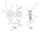
- FIG. 3 shows a plan view of a valve flap as can be used in the directional control fluid valve according to the invention
- FIG. 4 shows a sectional view along the line IV-IV of FIG. 3 ;
- FIG. 5 shows a schematic view, similar to FIG. 1 , of a directional control fluid valve according to the invention in the first flap position.
- a motor vehicle is denoted schematically by 10 .
- the motor vehicle 10 has an internal combustion engine 12 , the exhaust gases of which are discharged via an exhaust system 14 .
- the vehicle 10 is also assigned a urea injection system 20 by means of which urea can be injected into the exhaust system 14 for the reduction of nitrogen.
- the urea injection system 20 has a urea tank 22 in which a relatively large quantity of urea can be accommodated.
- the urea injection system 20 also has a urea injection valve 24 which constitutes a fluid consumer and by means of which the urea can be injected into the exhaust system 14 .
- Urea is a fluid which can freeze at low temperatures such as are regularly experienced by motor vehicles. It is therefore imperative for the urea injection system 20 to be emptied after the internal combustion engine 12 is shut down, with urea which is situated in the urea injection system 20 being pumped back into the urea tank 22 .
- a pump 26 is used which is preferably of unidirectional design.
- the pump 26 is driven on demand by means of a pump motor 28 (for example of an electric motor).
- a directional control fluid valve 30 is provided which, in the present case, is designed as a 4/2 directional control valve.
- the directional control fluid valve 30 is furthermore designed as a flap valve with a valve flap 32 which can be moved back and forth between a first flap position (basic position) shown in FIG. 1 and a second flap position shown in FIG. 2 .
- a flap lever 34 is provided which extends out of the directional control fluid valve 30 and which can be actuated by means of a valve actuator 36 .
- the valve actuator 36 preferably has an electromagnetic actuator 38 which can move an armature 40 .
- the armature 40 is coupled via a first spring 42 to the flap lever 34 . Furthermore, the armature 40 is coupled via a second spring 44 to the flap lever 34 .
- the directional control fluid valve 30 has a housing 50 which is composed preferably only of a base part 52 and a cover part 54 .
- the base part 52 and the cover part 54 are connected to one another via a parting plane 55 .
- a consumer port 58 which is connected to the urea injection valve 24 is provided on the base part 52 .
- a pressure port 60 for connecting to a pressure side of the pump 26 and a suction port 62 for connecting to a suction side of the pump 26 are also provided on the base part 52 .
- a tank port 56 for connecting to the urea tank 22 is provided on the base part 52 .
- a first valve chamber 64 within which a first blocking body 66 of the valve flap 32 is movable between the first flap position and the second flap position is provided in the housing 50 .
- a second valve chamber 68 within which a second blocking body 70 of the valve flap 32 is movable between the first and the second flap position is also provided in the housing 50 .
- the valve chambers 64 , 68 are arranged in the housing 50 in such a way that the parting plane 55 runs through the valve chambers 64 , 68 .
- the blocking bodies 66 , 70 are both integrally formed on the valve flap 32 and consequently move synchronously with one another between the first flap position and the second flap position.
- a first valve seat 72 and a second valve seat 74 are formed in the first valve chamber 64 .
- the first blocking body 66 is movable back and forth between the first valve seat 72 and the second valve seat 74 .
- a third valve seat 76 and a fourth valve seat 78 are formed in the second valve chamber 68 , between which the second blocking body 70 can move back and forth.
- the first valve seat 72 and the third valve seat 76 are provided on the base part 52 .
- the second valve seat 74 and the fourth valve seat 78 are provided on the cover part 54 .
- the pressure port 60 is connected via a first pressure port duct 80 to the first valve seat 72 .
- a second pressure port duct 82 connects the pressure port 60 to the fourth valve seat 78 .
- the second pressure port duct 82 runs both through the base part 52 and through the cover part 54 .
- a first suction port duct 84 connects the suction port 62 to the third valve seat 76 .
- a second suction port duct 86 connects the suction port 62 to the second valve seat 74 , with the second suction port duct 86 running both through the base part 52 and through the cover part 54 .
- a tank duct 88 connects the tank port 56 to the first valve chamber 64 , specifically independently of the position of the blocking bodies 66 , 70 .
- a consumer duct 90 connects the consumer port 58 to the second valve chamber 68 , specifically independently of the position of the second blocking body 70 .
- the second pressure port duct 82 has a first connecting duct 92 which extends obliquely from the pressure port 60 to a first transition point 94 in the region of the parting plane 55 .
- a first closed duct 96 is formed which extends from the first transition point 94 firstly in a direction perpendicular to the parting plane 55 and subsequently in a direction obliquely with respect thereto, before subsequently running back to the fourth valve seat 78 .
- the second suction port duct 86 has a second connecting duct 98 which extends from the suction port 62 in a direction obliquely with respect to the parting plane 55 to a second transition point 100 in the region of the parting plane 55 .
- a second closed duct 102 which connects the second transition point 100 to the second valve seat 74 is formed in the cover part 54 .
- the second closed duct 102 too, is designed so as to run from the second transition point 100 initially in a direction perpendicular to the parting plane 55 and subsequently obliquely with respect thereto, with the second closed duct 102 subsequently running back in the direction of the parting plane 55 to the second valve seat 74 .
- pressurized fluid is permanently present in the first closed duct 96 .
- the blocking body 70 bears against the fourth valve seat 78 (see FIG. 2 )
- said axial forces can however be limited in that the flow reversal point 104 of the first closed duct 96 has a very small cross-sectional area 106 which is preferably no larger than the cross-sectional area of the duct section which connects the flow reversal point 104 to the fourth valve seat 78 .
- the duct section which leads from the first transition point 94 to the flow reversal point 104 extends obliquely such that it opens out into the flow reversal point 104 and therefore does not increase the size of the area on which the pressurized fluid can act.
- That duct section of the closed duct 96 which leads from the transition point 94 to the flow reversal point 104 is inclined with respect to the parting plane 55 , specifically by an angle ⁇ .
- the angle a should be greater than 45°, preferably greater than 60°.
- the axial force with which the pressurized fluid pushes the cover part 54 away from the base part 52 can be reduced or minimized.
- the directional control fluid valve 30 may be operated as follows. In the basic position shown in FIG. 1 , in which the valve flap 32 is situated in the first flap position, the blocking bodies 66 , 70 press against the valve seats 72 , 76 . In this way, the first valve chamber 64 is connected to the suction port 62 and the second valve chamber 68 is connected to the pressure port 60 .
- the exhaust gas can be purified, in particular freed from nitrogen oxides. It is self-evident that urea is “consumed” in this way, such that after a certain operating duration, the urea tank 22 may need to be re-filled.
- the pump 26 can generate a very high pressure, for example in the region of 9 bar, such that with corresponding nozzle design, the urea can be injected into the exhaust system 14 at very high pressure and consequently in finely atomized form, and consequently with high efficiency.
- the valve actuator 36 is used, by means of which a force FF can be exerted on the valve flap 32 .
- the first flap position may also be configured to be self-holding, with the fluid pressure generated by the pump 26 serving to hold the valve flap 32 in the first flap position.
- valve actuator 36 is actuated such that an opposing force FL is exerted on the valve flap 32 .
- the valve flap 32 is pushed into the second flap position, in which the first blocking body 66 bears against the second valve seat and the second blocking body 70 bears against the fourth valve seat 78 .
- the first valve chamber 64 is connected to the pressure port 60 .
- the second valve chamber 68 is connected to the suction port 62 .
- fluid can be pumped from the urea injection valve 24 back into the tank 22 via the consumer port 58 , the consumer duct 90 , the second valve chamber 68 , the first suction port duct 84 , the suction port 62 , the pump 26 , the pressure port 60 , the first pressure port duct 80 , the first valve chamber 64 , the tank duct 88 and the tank port 56 .
- the throughflow path established here is denoted by L and indicated by arrows in FIG. 2 .
- FIGS. 3 and 4 schematically show a valve flap 32 which is preferably used in a directional control fluid valve 30 according to the invention.
- the valve flap 32 has a flap lever 34 which may for example extend out of the housing 50 and which may be engaged on directly or indirectly by a valve actuator 36 .
- the flap lever 34 has a first web which extends into the interior of the housing 50 and which, at its end, bears the first blocking body 66 .
- the flap lever 34 has a second web which extends into the housing 50 and which, at its free end, bears the second blocking body 70 .
- a first valve chamber seal 108 and a second valve chamber seal 110 are also integrally formed on the flap lever 34 .
- the valve chamber seals 108 , 110 are in each case of annular design such that they can seal off the valve chambers 64 , 68 in the region of the parting plane 55 (as shown for example in FIG. 5 ).
- valve flap 32 is designed such that the blocking bodies 66 , 70 are pivoted, specifically about a pivot axis 111 which is shown in FIG. 4 , synchronously with movements of that part of the flap lever 34 which extends out of the housing 50 .
- the flap lever 34 is therefore formed as a two-sided lever about the pivot axis 111 .
- the blocking bodies 66 , 70 are mechanically connected to one another by means of the flap lever 34 , such that forces acting on one blocking body 66 are transmitted via the flap lever 34 to the other blocking body 70 and vice versa.
- FIG. 5 schematically shows a detail of a directional control fluid valve 30 according to the invention, the design and function of which generally corresponds to the directional control fluid valve 30 described in FIGS. 1 and 2 . Identical elements are therefore denoted by the same reference numerals. Only differences will be explained below.
- valve flap 32 is of similar design, in terms of construction and function, to the valve flap 32 shown in FIGS. 3 and 4 .
- FIG. 5 also shows that the first valve seat 72 and the third valve seat 76 , against which the blocking bodies 66 , 70 bear in the first flap position, are of different design.
- the first flap position (which corresponds to the state of FIG. 1 )
- the first blocking body 66 In the first flap position (which corresponds to the state of FIG. 1 ), the first blocking body 66 must seal off the first valve seat 72 with respect to the fluid pressure provided at the pressure port 60 .
- the pressure acting on the first blocking body 66 is indicated in FIG. 5 by an arrow.
- a fluid pressure of equal magnitude acts on the second blocking body 70 but in the opposite direction, as likewise indicated in FIG. 5 by an arrow.
- valve seats 72 , 76 are of different design, in such a way that the pressure acting on the first blocking body 66 exerts a load on the first area 112 , which substantially corresponds to the cross section of the first pressure port duct 80 .
- the third valve seat 76 is shaped such that the pressure acting on the second blocking body 70 exerts a load on a second area 114 which is considerably larger than the first area 112 which is subjected to pressure loading. Since the force exerted on the blocking bodies 66 , 70 in each case constitutes a product of the pressure and the area 112 , 114 which is subjected to pressure loading, a greater overall force is exerted on the valve flap 32 in the direction of the first flap position shown in FIG. 5 than in the opposite direction. Since the two blocking bodies 66 , 70 are rigidly connected to one another by means of the flap lever 34 , the valve flap 32 is consequently held in the first flap position shown in FIG. 5 solely on account of the fluid pressure.
Landscapes
- Engineering & Computer Science (AREA)
- General Engineering & Computer Science (AREA)
- Mechanical Engineering (AREA)
- Chemical & Material Sciences (AREA)
- Chemical Kinetics & Catalysis (AREA)
- Electromagnetism (AREA)
- Physics & Mathematics (AREA)
- Health & Medical Sciences (AREA)
- Toxicology (AREA)
- Combustion & Propulsion (AREA)
- Multiple-Way Valves (AREA)
- Lift Valve (AREA)
- Valve Housings (AREA)
Applications Claiming Priority (4)
| Application Number | Priority Date | Filing Date | Title |
|---|---|---|---|
| DE102008039420 | 2008-08-13 | ||
| DE102008039420.3 | 2008-08-13 | ||
| DE102008039420A DE102008039420B4 (de) | 2008-08-13 | 2008-08-13 | Fluidwegeventil |
| PCT/EP2009/005874 WO2010017980A1 (de) | 2008-08-13 | 2009-08-13 | Fluidwegeventil |
Related Parent Applications (1)
| Application Number | Title | Priority Date | Filing Date |
|---|---|---|---|
| PCT/EP2009/005874 Continuation WO2010017980A1 (de) | 2008-08-13 | 2009-08-13 | Fluidwegeventil |
Publications (2)
| Publication Number | Publication Date |
|---|---|
| US20110198528A1 US20110198528A1 (en) | 2011-08-18 |
| US8403002B2 true US8403002B2 (en) | 2013-03-26 |
Family
ID=41346076
Family Applications (1)
| Application Number | Title | Priority Date | Filing Date |
|---|---|---|---|
| US13/023,142 Active 2029-11-14 US8403002B2 (en) | 2008-08-13 | 2011-02-08 | Directional control fluid valve |
Country Status (5)
| Country | Link |
|---|---|
| US (1) | US8403002B2 (de) |
| EP (1) | EP2313673B1 (de) |
| CN (1) | CN102203477B (de) |
| DE (1) | DE102008039420B4 (de) |
| WO (1) | WO2010017980A1 (de) |
Cited By (1)
| Publication number | Priority date | Publication date | Assignee | Title |
|---|---|---|---|---|
| US10344659B2 (en) | 2014-12-04 | 2019-07-09 | Cummins Power Generation Ip, Inc. | Auxiliary diesel exhaust fluid systems |
Families Citing this family (3)
| Publication number | Priority date | Publication date | Assignee | Title |
|---|---|---|---|---|
| DE102010044090A1 (de) * | 2010-11-18 | 2012-05-24 | Robert Bosch Gmbh | Ventil mit einem Gehäuse aus Kunststoff |
| DE102011010784A1 (de) * | 2011-02-09 | 2012-08-09 | Rolf Prettl | Harnstoffeinspritzsystem und Ventilanordnung hierfür |
| DE102017209255A1 (de) * | 2017-06-01 | 2018-12-06 | Robert Bosch Gmbh | Fluidventil |
Citations (19)
| Publication number | Priority date | Publication date | Assignee | Title |
|---|---|---|---|---|
| US2990853A (en) * | 1958-01-23 | 1961-07-04 | Nat Tank Co | Rotary valve |
| EP0022264A1 (de) | 1979-07-09 | 1981-01-14 | Eaton Corporation | Durchflussklappe |
| US4285497A (en) * | 1977-06-02 | 1981-08-25 | Burkert Gmbh | Electromagnetically actuated valve |
| US4361121A (en) * | 1980-04-17 | 1982-11-30 | Robert Bosch Gmbh | Control device for shutting off a diesel engine |
| US4574841A (en) * | 1983-09-21 | 1986-03-11 | J. Lorch Gesellschaft & Co. Kg | Rocker lever solenoid valve |
| US4632082A (en) * | 1984-09-12 | 1986-12-30 | Toyota Jidosha Kabushiki Kaisha | Device for driving a rotary valve |
| US4765370A (en) * | 1985-11-29 | 1988-08-23 | Fujikura Rubber Ltd. | Directional control valve |
| US4934406A (en) * | 1986-11-03 | 1990-06-19 | Parker-Hannifin Corporation | Throttling valve |
| US5139226A (en) * | 1990-06-29 | 1992-08-18 | Mechanical Systems Analysis, Inc. | Electro-mechanical fluid control valve |
| US5275207A (en) * | 1991-09-07 | 1994-01-04 | Mercedes-Benz Ag | Multiway valve |
| DE4224389A1 (de) | 1992-07-23 | 1994-01-27 | Roemer J C Avs Gmbh | Ventil mit T-förmigem bzw. N-förmigem, wippenartigem Ventilglied |
| US5799696A (en) * | 1995-10-18 | 1998-09-01 | Parker-Hannifin Corporation | Solenoid actuated toggle valve |
| US5983941A (en) * | 1997-04-30 | 1999-11-16 | Nass Magnet Gmbh | Multiple-way valve |
| EP1013942A2 (de) | 1998-12-23 | 2000-06-28 | Bürkert Werke GmbH & Co. | Steuerelement für Fluid |
| EP1154178A2 (de) | 2000-05-08 | 2001-11-14 | Smc Corporation | Kolbenangetriebenes Ventil |
| US20030230082A1 (en) | 2002-06-14 | 2003-12-18 | Volvo Construction Equipment Holding Sweden Ab | Hydraulic circuit for boom cylinder combination having float function |
| US6880572B2 (en) * | 2002-04-15 | 2005-04-19 | Jenara Enterprises Ltd. | Exhaust gas control valve, apparatus and method of controlling exhaust gas flow |
| JP2005169183A (ja) | 2003-12-08 | 2005-06-30 | Horyo Corp | 液体濾過装置および切換弁 |
| WO2005108840A1 (de) | 2004-04-30 | 2005-11-17 | Biechele Guenter | Klappenventil |
-
2008
- 2008-08-13 DE DE102008039420A patent/DE102008039420B4/de not_active Expired - Fee Related
-
2009
- 2009-08-13 EP EP20090777857 patent/EP2313673B1/de active Active
- 2009-08-13 WO PCT/EP2009/005874 patent/WO2010017980A1/de active Application Filing
- 2009-08-13 CN CN2009801407703A patent/CN102203477B/zh active Active
-
2011
- 2011-02-08 US US13/023,142 patent/US8403002B2/en active Active
Patent Citations (23)
| Publication number | Priority date | Publication date | Assignee | Title |
|---|---|---|---|---|
| US2990853A (en) * | 1958-01-23 | 1961-07-04 | Nat Tank Co | Rotary valve |
| US4285497A (en) * | 1977-06-02 | 1981-08-25 | Burkert Gmbh | Electromagnetically actuated valve |
| EP0022264A1 (de) | 1979-07-09 | 1981-01-14 | Eaton Corporation | Durchflussklappe |
| US4361121A (en) * | 1980-04-17 | 1982-11-30 | Robert Bosch Gmbh | Control device for shutting off a diesel engine |
| US4574841A (en) * | 1983-09-21 | 1986-03-11 | J. Lorch Gesellschaft & Co. Kg | Rocker lever solenoid valve |
| US4632082A (en) * | 1984-09-12 | 1986-12-30 | Toyota Jidosha Kabushiki Kaisha | Device for driving a rotary valve |
| US4765370A (en) * | 1985-11-29 | 1988-08-23 | Fujikura Rubber Ltd. | Directional control valve |
| US4934406A (en) * | 1986-11-03 | 1990-06-19 | Parker-Hannifin Corporation | Throttling valve |
| US5139226A (en) * | 1990-06-29 | 1992-08-18 | Mechanical Systems Analysis, Inc. | Electro-mechanical fluid control valve |
| US5275207A (en) * | 1991-09-07 | 1994-01-04 | Mercedes-Benz Ag | Multiway valve |
| DE4224389A1 (de) | 1992-07-23 | 1994-01-27 | Roemer J C Avs Gmbh | Ventil mit T-förmigem bzw. N-förmigem, wippenartigem Ventilglied |
| US5799696A (en) * | 1995-10-18 | 1998-09-01 | Parker-Hannifin Corporation | Solenoid actuated toggle valve |
| US5983941A (en) * | 1997-04-30 | 1999-11-16 | Nass Magnet Gmbh | Multiple-way valve |
| EP1013942A2 (de) | 1998-12-23 | 2000-06-28 | Bürkert Werke GmbH & Co. | Steuerelement für Fluid |
| US6286548B1 (en) * | 1998-12-23 | 2001-09-11 | Burkert Werke Gmbh & Co | Fluid control element |
| EP1154178A2 (de) | 2000-05-08 | 2001-11-14 | Smc Corporation | Kolbenangetriebenes Ventil |
| US6880572B2 (en) * | 2002-04-15 | 2005-04-19 | Jenara Enterprises Ltd. | Exhaust gas control valve, apparatus and method of controlling exhaust gas flow |
| US20030230082A1 (en) | 2002-06-14 | 2003-12-18 | Volvo Construction Equipment Holding Sweden Ab | Hydraulic circuit for boom cylinder combination having float function |
| FR2842225A1 (fr) | 2002-06-14 | 2004-01-16 | Volvo Constr Equip Holding Se | Circuit hydraulique pour une combinaison de verin de fleche ayant une fonction flotteur |
| CN1470717A (zh) | 2002-06-14 | 2004-01-28 | �ֶ��ֽ����豸�عɣ���䣩����˾ | 用于转臂油缸组合的具有浮动功能的液压回路 |
| US6892535B2 (en) | 2002-06-14 | 2005-05-17 | Volvo Construction Equipment Holding Sweden Ab | Hydraulic circuit for boom cylinder combination having float function |
| JP2005169183A (ja) | 2003-12-08 | 2005-06-30 | Horyo Corp | 液体濾過装置および切換弁 |
| WO2005108840A1 (de) | 2004-04-30 | 2005-11-17 | Biechele Guenter | Klappenventil |
Non-Patent Citations (1)
| Title |
|---|
| English translation of CN First Office Action with Search Report issued by the State Intellectual Property Office (SIPO) on Aug. 30, 2012 for CN Patent Application No. 200980140770.3. |
Cited By (1)
| Publication number | Priority date | Publication date | Assignee | Title |
|---|---|---|---|---|
| US10344659B2 (en) | 2014-12-04 | 2019-07-09 | Cummins Power Generation Ip, Inc. | Auxiliary diesel exhaust fluid systems |
Also Published As
| Publication number | Publication date |
|---|---|
| DE102008039420B4 (de) | 2011-04-28 |
| CN102203477A (zh) | 2011-09-28 |
| CN102203477B (zh) | 2013-07-31 |
| US20110198528A1 (en) | 2011-08-18 |
| WO2010017980A8 (de) | 2011-06-30 |
| EP2313673B1 (de) | 2012-06-20 |
| WO2010017980A1 (de) | 2010-02-18 |
| EP2313673A1 (de) | 2011-04-27 |
| DE102008039420A1 (de) | 2010-02-18 |
Similar Documents
| Publication | Publication Date | Title |
|---|---|---|
| US8844283B2 (en) | Exhaust-gas turbocharger with a bypass valve | |
| US9562455B2 (en) | Dosing system for a liquid reducing agent | |
| KR101964896B1 (ko) | 밸브 | |
| US8403002B2 (en) | Directional control fluid valve | |
| US20080073605A1 (en) | Fluid-controlled valve | |
| EP0826876A1 (de) | Kraftstoffeinspritzvorrichtung für Brennkraftmaschinen | |
| CN101171416A (zh) | 具有休止位置的egr阀 | |
| KR20000070560A (ko) | 배기 가스 재순환 장치 | |
| CN101932800A (zh) | 废气调节系统和废气调节方法 | |
| JP2005530951A (ja) | 流れ分岐装置及びエコロジー弁 | |
| US9765898B2 (en) | Valve device for switching or metering a fluid | |
| CN103649482B (zh) | 计量系统和用于计量系统的3/2换向阀 | |
| JP2009537744A (ja) | サクションジェットポンプ | |
| CN104685170B (zh) | 阀促动机构和配备有此阀促动机构的机动车辆 | |
| JP4335544B2 (ja) | 特に内燃機関に用いられる燃料噴射装置の高圧液体システム内の接続部を制御するための弁 | |
| CN101553388B (zh) | 多重保护阀 | |
| US9551310B2 (en) | Valve device | |
| CN113454329A (zh) | 用于可选地释放或阻断用于排气后处理设备的排气再循环流或二次空气流的阀装置 | |
| CN103201479B (zh) | 用于内燃机的空气连接器 | |
| JP2014105873A (ja) | 自動車の排ガス流動用バイパス弁 | |
| US7513441B2 (en) | Valve for controlling a connection in a high-pressure fuel injection apparatus for an internal combustion engine | |
| CN215520998U (zh) | 一种动态停缸驱动装置、发动机及车辆 | |
| US20140117264A1 (en) | Valve | |
| US9080538B2 (en) | Injector assembly for an injection valve | |
| CN104160120A (zh) | 阀致动器布置 |
Legal Events
| Date | Code | Title | Description |
|---|---|---|---|
| AS | Assignment |
Owner name: PRETTL, ROLF, GERMANY Free format text: ASSIGNMENT OF ASSIGNORS INTEREST;ASSIGNORS:DETTINGER, JUERGEN;BORST, PETER;REEL/FRAME:026193/0251 Effective date: 20110408 |
|
| FEPP | Fee payment procedure |
Free format text: PAYOR NUMBER ASSIGNED (ORIGINAL EVENT CODE: ASPN); ENTITY STATUS OF PATENT OWNER: LARGE ENTITY |
|
| STCF | Information on status: patent grant |
Free format text: PATENTED CASE |
|
| FEPP | Fee payment procedure |
Free format text: PAYER NUMBER DE-ASSIGNED (ORIGINAL EVENT CODE: RMPN); ENTITY STATUS OF PATENT OWNER: LARGE ENTITY Free format text: PAYOR NUMBER ASSIGNED (ORIGINAL EVENT CODE: ASPN); ENTITY STATUS OF PATENT OWNER: LARGE ENTITY |
|
| FPAY | Fee payment |
Year of fee payment: 4 |
|
| FEPP | Fee payment procedure |
Free format text: MAINTENANCE FEE REMINDER MAILED (ORIGINAL EVENT CODE: REM.); ENTITY STATUS OF PATENT OWNER: LARGE ENTITY |
|
| FEPP | Fee payment procedure |
Free format text: 7.5 YR SURCHARGE - LATE PMT W/IN 6 MO, LARGE ENTITY (ORIGINAL EVENT CODE: M1555); ENTITY STATUS OF PATENT OWNER: LARGE ENTITY |
|
| MAFP | Maintenance fee payment |
Free format text: PAYMENT OF MAINTENANCE FEE, 8TH YEAR, LARGE ENTITY (ORIGINAL EVENT CODE: M1552); ENTITY STATUS OF PATENT OWNER: LARGE ENTITY Year of fee payment: 8 |