US8326005B2 - Guide apparatus, image pickup apparatus, image pickup system, and guide method - Google Patents

Guide apparatus, image pickup apparatus, image pickup system, and guide method Download PDF

Info

Publication number
US8326005B2
US8326005B2 US12/195,672 US19567208A US8326005B2 US 8326005 B2 US8326005 B2 US 8326005B2 US 19567208 A US19567208 A US 19567208A US 8326005 B2 US8326005 B2 US 8326005B2
Authority
US
United States
Prior art keywords
guide
image pickup
wrist
palm
finger
Prior art date
Legal status (The legal status is an assumption and is not a legal conclusion. Google has not performed a legal analysis and makes no representation as to the accuracy of the status listed.)
Expired - Fee Related, expires
Application number
US12/195,672
Other versions
US20090123041A1 (en
Inventor
Shiro Tani
Current Assignee (The listed assignees may be inaccurate. Google has not performed a legal analysis and makes no representation or warranty as to the accuracy of the list.)
Fujitsu Ltd
Original Assignee
Fujitsu Ltd
Priority date (The priority date is an assumption and is not a legal conclusion. Google has not performed a legal analysis and makes no representation as to the accuracy of the date listed.)
Filing date
Publication date
Application filed by Fujitsu Ltd filed Critical Fujitsu Ltd
Assigned to FUJITSU LIMITED reassignment FUJITSU LIMITED ASSIGNMENT OF ASSIGNORS INTEREST (SEE DOCUMENT FOR DETAILS). Assignors: TANI, SHIRO
Publication of US20090123041A1 publication Critical patent/US20090123041A1/en
Application granted granted Critical
Publication of US8326005B2 publication Critical patent/US8326005B2/en
Expired - Fee Related legal-status Critical Current
Adjusted expiration legal-status Critical

Links

Images

Classifications

    • GPHYSICS
    • G06COMPUTING; CALCULATING OR COUNTING
    • G06VIMAGE OR VIDEO RECOGNITION OR UNDERSTANDING
    • G06V40/00Recognition of biometric, human-related or animal-related patterns in image or video data
    • G06V40/10Human or animal bodies, e.g. vehicle occupants or pedestrians; Body parts, e.g. hands
    • G06V40/14Vascular patterns
    • G06V40/145Sensors therefor
    • GPHYSICS
    • G06COMPUTING; CALCULATING OR COUNTING
    • G06VIMAGE OR VIDEO RECOGNITION OR UNDERSTANDING
    • G06V40/00Recognition of biometric, human-related or animal-related patterns in image or video data
    • G06V40/60Static or dynamic means for assisting the user to position a body part for biometric acquisition
    • G06V40/63Static or dynamic means for assisting the user to position a body part for biometric acquisition by static guides

Definitions

  • the present invention relates to a guide apparatus for guiding a palm to a position suitable for photographing, an image pickup apparatus, am image pickup system, and a guide method.
  • biometrics technology has increasingly been used as a substitute for authentication using a password or card.
  • Fingerprint and iris, etc. have widely been used as biometrics authentication data.
  • vein authentication which uses image recognition and optical technology to scan the normally invisible vein pattern of the palm, back of the hand, fingers, etc. has the properties of being highly accurate and highly resistant to counterfeiting, impersonation, and other dishonest actions.
  • Hemoglobin reduced hemoglobin
  • the palm is irradiated with the near infrared ray, and the location of veins is recognized by the degree of strength of the reflected near infrared ray.
  • non-contact vein authentication system that performs authentication without giving user a feeling of reluctance by photographing veins of the palm in a non-contact manner is now widely used.
  • FIG. 11 is a view showing a conventional guide apparatus
  • FIG. 12 is a view showing another conventional guide apparatus.
  • a guide apparatus 5 has a wrist guide 201 , a middle finger guide 202 , and a non-contact sensor unit 40 .
  • the wrist guide 201 fixes the wrist of a user to be subjected to the vein authentication
  • middle finger guide 202 fixes the middle finger of the user
  • non-contact sensor unit 40 photographs the palm of the user fixed by the wrist guide 201 and middle finger guide 202 .
  • a guide apparatus 6 has a wrist guide 301 ′ a middle finger guide 302 , a placement portion 303 , and a non-contact sensor unit 40 .
  • the wrist guide 301 fixes the wrist of a user to be subjected to the vein authentication
  • middle finger guide 302 fixes the middle finger of the user
  • placement portion 303 guides the user's hand to be placed on the guide apparatus 6 in such a manner to spread his or her fingers
  • non-contact sensor unit 40 photographs the palm of the user fixed by the wrist guide 301 , middle finger guide 302 , and placement portion 303 .
  • Patent Document 1 Jpn. Pat. Appln. Laid-Open Publication No. 11-47119
  • the position of the palm relative to the non-contact sensor unit 40 may change in the direction denoted by the arrow between the registration time and authentication time, as shown in FIG. 13 and, further, the degree of spread of the fingers may change between the registration time and authentication time.
  • the wrist guide 301 in the case where the width of the user's wrist is smaller than the width set by the wrist guide 301 , the wrist guide 301 cannot fix the user's wrist as shown in FIG. 14 , which may cause a change in the position of the user's wrist in the direction denoted by the arrow between the registration time and authentication time.
  • the non-contact sensor unit 40 may photograph different portions of the palm between the registration time and authentication time. In this case, although the palm of the same user is subjected to the vein authentication, the vein pattern is determined to be different from that at the registration time, with the result that the relevant user is not authenticated.
  • the present invention has been made to solve the above problems, and an object thereof is to provide a guide apparatus, an image pickup apparatus, an image pickup system, and a guide method capable of guiding palms of various sizes to a position suitable for photographing.
  • a guide apparatus that guides a palm to be photographed by an image pickup apparatus to a position suitable for photographing, including: a placement portion that has a planar surface on which the palm is placed in the image pickup direction of the image pickup apparatus and that supports the palm placed on the planar surface so that the palm can be photographed by the image pickup apparatus through an opening formed in the planar surface; a finger guide that is provided on the placement portion at the one end side of the opening and formed of two finger guide members with a predetermined distance therebetween and that positions a predetermined finger between the finger guide members; and a wrist guide that is provided on the placement portion at the other end side (opposite to the one end side) of the opening in a V-shaped manner with respect to the image pickup direction of the image pickup apparatus for supporting a wrist and that is movably arranged such that when the wrist is brought into contact with the V-shaped inclined surface, the wrist guide is moved by the load of wrist and guides the wrist in the inclined direction while moving the
  • an image pickup apparatus including: an image pickup section that photographs a palm; a placement portion that has a planar surface on which the palm is placed in the image pickup direction of the image pickup section and that supports the palm placed on the planar surface so that the palm can be photographed by the image pickup section through an opening formed in the planar surface; a finger guide that is provided on the placement portion at the one end side of the opening and that positions a predetermined finger placed on the placement portion; and a wrist guide that is provided on the placement portion at the other end side (opposite to the one end side) of the opening in a V-shaped manner with respect to the image pickup direction of the image pickup section for supporting a wrist and that is movably arranged such that when the wrist is brought into contact with the V-shaped inclined surface, the wrist guide is moved by the load of wrist and guides the wrist in the inclined direction while moving the palm to a predetermined position with respect to the opening in cooperation with the finger guide.
  • an image pickup system including: an image pickup section that photographs a palm; a placement portion that has a detection section for detecting the palm set at a position at which the image pickup section can photograph the palm and a planar surface on which the palm is placed in the image pickup direction of the image pickup section and that supports the palm placed on the planar surface so that the palm can be photographed by the image pickup section through an opening formed in the planar surface; a finger guide that is provided on the placement portion at the one end side of the opening and that positions a predetermined finger placed on the placement portion; a wrist guide that is provided on the placement portion at the other end side (opposite to the one end side) of the opening in a V-shaped manner with respect to the image pickup direction of the image pickup section for supporting a wrist and that is movably arranged such that when the wrist is brought into contact with the V-shaped inclined surface, the wrist guide is moved by the load of wrist and guides the wrist in the inclined direction while moving to position the palm to a predetermined
  • a guide method that guides a palm to a position suitable for photographing in the case where a camera provided in a casing is used to photograph, through an opening formed in the casing, the palm which is guided to the front of the opening, including: providing, at the one end side of the opening, a finger guide for positioning a predetermined finger, and providing, at the other end side (opposite to the one end side) of the opening, a wrist guide for positioning a wrist, wherein when the wrist is brought into contact with an inclined surface provided in a V-shaped manner with respect to the image pickup direction, the wrist guide is moved by the load of wrist and guides the wrist in the inclined direction while moving the palm to a predetermined position with respect to the opening in cooperation with the finger guide.
  • a guide apparatus capable of guiding palms of various sizes to a position suitable for photographing.
  • FIG. 1 is a view showing an image pickup system according to an embodiment of the present invention
  • FIG. 2 is a view showing the image pickup range in palm vein authentication
  • FIG. 3 is a view showing a configuration of an image pickup apparatus according to the present embodiment
  • FIG. 4 is a view showing a configuration of the image pickup apparatus according to the present embodiment.
  • FIG. 5 is a view showing a state of a wrist guide in the case where a comparatively thin wrist is placed thereon;
  • FIG. 6 is a view showing a state of a wrist guide in the case where a comparatively thick wrist is placed thereon;
  • FIG. 7 is a view showing a middle finger fixed in a middle finger guide
  • FIG. 8 is a view showing a positional relationship between the middle finger and middle finger guide
  • FIG. 9 is a view showing a configuration of a non-contact sensor unit
  • FIG. 10 is a flowchart showing operation of non-contact vein authentication processing
  • FIG. 11 is a view showing a conventional guide apparatus
  • FIG. 12 is a view showing another conventional guide apparatus
  • FIG. 13 is a view showing a problem posed in the guide apparatus of FIG. 11 ;
  • FIG. 14 is a view showing a problem posed in the guide apparatus of FIG. 12 .
  • FIG. 1 is a view showing an image pickup system according to the present embodiment
  • FIG. 2 is a view showing the image pickup range in palm vein authentication.
  • An image pickup system S includes an image pickup apparatus 1 (guide apparatus) and a personal computer 2 (control apparatus).
  • the image pickup apparatus 1 and personal computer 2 are connected to each other by a USB cable 3 .
  • non-contact vein authentication is conducted for a user to login to the personal computer 2 , and that the user has previously registered, in the personal computer 2 , a vein pattern within a vein range R shown in FIG. 2 of a palm of his or her left or right hand by using the image pickup apparatus 1 and performs authentication at the is login time using the palm of the same hand.
  • processing concerning the non-contact vein authentication and power supply to the image pickup apparatus 1 are made by the personal computer 2 using the USB cable 3 .
  • the personal computer 2 may be any apparatus, such as an ATM, as long as it can execute processing concerning the non-contact vein authentication.
  • the USB cable 3 may be any configuration as long as it can connect the image pickup apparatus 1 to an apparatus that executes processing concerning the vein authentication.
  • FIGS. 3 and 4 are views showing a configuration of the image pickup apparatus according to the present embodiment.
  • FIG. 3 is a top perspective view of the image pickup apparatus
  • FIG. 4 is a side perspective view thereof.
  • the image pickup apparatus 1 has a placement portion 10 , a wrist guide 20 provided on the placement portion 10 , a middle finger guide 30 (finger guide) provided on the placement portion 10 , a non-contact sensor unit 40 having a camera 40 a , and a detachable USB cable 3 .
  • the non-contact sensor unit 40 has a not-shown USB connection portion.
  • the placement portion 10 , wrist guide 20 , and middle finger guide 30 constitutes a palm guide apparatus in the present embodiment.
  • the placement portion 10 has a planar surface H perpendicular to the image pickup direction of the image pickup apparatus 1 (image pickup direction of the camera 40 a ) and supports a palm placed on the planar surface H such that the camera 40 a can photograph the palm through an opening portion W formed in the planar surface H.
  • the opening portion W is formed above the non-contact sensor unit 40 and is made to have a size slightly larger than an image pickup range F of the non-contact sensor unit 40 at a portion corresponding to the image pickup range F.
  • the non-contact sensor unit 40 is has a camera 40 a and photographs the vain pattern on the palm within the image pickup range F.
  • the wrist guide 20 has, at the center thereof, a flat portion 20 a and has, at both ends thereof projection portions 20 b and 20 b having inclined surfaces VF facing each other.
  • the wrist guide 20 is so formed as to project upward from the planar surface H. Further, the wrist guide 20 is so supported by an appropriate portion (support member) 1 of the casing of the image pickup apparatus 1 through a compression coil spring 50 attached to the lower surface of the wrist guide 20 as to be movable in the up-down direction.
  • the height of the flat portion 20 a of the wrist guide 20 is substantially the same as the height of the placement portion 10 and, when the wrist is placed on the flat portion 20 a , the wrist guide 20 moves downward until the wrist or its surrounding portion is brought into contact with the planar surface of the placement portion 10 .
  • the wrist guide 20 guides the wrist downward for positioning until the wrist is brought into contact with the planar surface so that the palm placed on the placement portion 10 is adequately photographed.
  • the inclined surfaces VF of the projection portions 20 b and 20 b are inclined such that the distance between the projection portions 20 b and 20 b is narrower at the lower portion than at the upper portion.
  • the two projection portions 20 b and 20 b of the wrist guide 20 project from the planar surface H such that their inclined surfaces on which the wrist is placed are away from each other.
  • the projection portions 20 b and 20 b are so formed as to project upward from two holes formed in the planar surface H
  • the hole may be formed in the planar surface H such that the entire wrist guide 20 as viewed from the above faces outside the placement portion, as long as the height of flat portion 20 a of the wrist guide 20 is the same as the height of the planar surface H.
  • the middle finger guide 30 is constituted by two cone-like projections (finger guide members) 30 a and 30 a .
  • the projections 30 a and 30 a are provided on the placement portion with a predetermined distance therebetween so that the middle finger is positioned to the center therebetween.
  • the above wrist guide 20 , middle finger guide 30 , and non-contact sensor unit 40 are arranged such that the centers thereof are arranged on a center line C of the placement portion 10 as shown in FIG. 3 .
  • the palm can be set at the same position both at the registration time and authentication time.
  • the middle finger is fixed on the center line C, it is possible for a user to correctly position the palm regardless of whether a left or right hand is placed. Further, when the palm is placed on the placement portion, the palm is fixed in an opened state, thereby preventing the degree of spread of the fingers from changing between the registration time and authentication time. Furthermore, in this configuration, the thumb and little fingers are placed on the placement portion 10 , and middle finger and wrist are fixed, so that the angle of the palm relative to the non-contact sensor unit 40 is always kept constant. For example, the palm face is set parallel to the opening plane of the opening portion W.
  • middle finger guide 30 side and wrist guide 20 side of the placement portion 10 are referred to as “front side” and “rear side” thereof.
  • the middle finger guide 30 may be a guide for another finger.
  • FIG. 5 is a view showing a state of the wrist guide in the case where a comparatively thin wrist is placed thereon
  • FIG. 6 is a view showing a state of the wrist guide in the case where a comparatively thick wrist is placed thereon.
  • the wrist guide 20 is pressed down until the wrist H 2 contacts the planar surface H of the placement portion 10 , so that the distance between the left and right projection portions 20 b of the wrist guide 20 at the height of the planar surface H is made larger.
  • the wrist guide 20 can accommodate wrists of various sizes.
  • the distance between the left and right inclined surfaces of the wrist guide 20 is set to correspond to a thin wrist, and the wrist guide 20 having the left and right projection portions 20 b is constituted as one unit and thus the left and right projection portions 20 b are pressed down by the same degree.
  • the wrist guide 20 is configured to be pressed down in the present embodiment, another configuration may be employed.
  • the left and right projection portions 20 b may slide in the outside is direction by the same distance.
  • FIG. 7 is a view showing a middle finger fixed in the middle finger guide
  • FIG. 8 is a view showing a positional relationship between the middle finger and middle finger guide.
  • FIG. 7 shows a state where the image pickup apparatus is viewed from the front.
  • the cone-like projections 30 a and 30 a of the middle finger guide 30 position a middle finger M to substantially the center therebetween.
  • the inclined surfaces of the cone-like projections 30 a and 30 a allows the middle finger guide 30 to accommodate middle fingers of various sizes. For example, it is possible to fix a middle finger thicker than assumed in the middle of the inclined surfaces of the projections 30 a and 30 a as shown in FIG. 7 .
  • the middle finger guide 30 holds a portion between a proximal interphalangeal joint (PIP joint) P of the middle finger and base thereof, especially, a portion B 1 at which the width of the proximal phalanx B becomes thinner, thereby preventing movement of the middle finger in the direction denoted by the arrow.
  • PIP joint proximal interphalangeal joint
  • the thumb between its fingertip and interphalangeal joint (IP joint) I and a portion of the little finger between its fingertip and distal interphalangeal joint (DIP joint) D are placed on the placement portion 10 .
  • the guide apparatus it is possible for the guide apparatus to accommodate hands of various sizes, as well as to make constant the degree of spread of fingers and position/angle of the palm relative to the non-contact sensor unit 40 .
  • the non-contact sensor unit 40 can photograph the palm at the same position and at the same angle both at the registration time and authentication time.
  • FIG. 9 is a view showing a configuration of the non-contact sensor is unit.
  • the non-contact sensor unit 40 has an infrared sensor 401 (image pickup section corresponding to the camera 40 a ), a condenser lens 402 (image pickup section corresponding to the camera 40 a ), a near-infrared light-emitting device 403 (image pickup section corresponding to the camera 40 a ), a distance sensor 404 (detection section), and an infrared filter 405 .
  • the near-infrared light-emitting device 403 emits a near-infrared ray in an upward direction to irradiate the palm placed on the image pickup apparatus 1 with the near-infrared ray.
  • the condenser lens 402 collects a light irradiated to the palm on the image pickup range F shown in FIG. 1 by the near-infrared light-emitting device 403 and reflected therefrom on the infrared sensor 401 .
  • the distance sensor 404 detects an object on the non-contact sensor unit 40 and measures the distance between the object and sensor unit 40 .
  • the infrared filter 405 shields visible light.
  • FIG. 10 is a flowchart showing operation of non-contact vein authentication processing. It is assumed that control for the non-contact sensor unit and authentication processing are performed by the personal computer 2 and that a vein pattern image of a target user has previously been registered in the personal computer 2 .
  • the personal computer 2 uses the distance sensor 404 to perform detection (S 101 ) to determine whether there exists an object (palm) on the non-contact sensor unit 40 (S 102 ).
  • the personal computer 2 uses the distance sensor 404 to measure the distance between the distance sensor 404 and object (S 103 ) and determines whether the measured distance is suitable for photographing a vein pattern (S 104 ).
  • the personal computer 2 uses the infrared sensor 401 to photograph the object (S 105 ) and compares the photographed vein pattern image and registered vein pattern image (S 106 ) to determine whether they match each other (S 107 ).
  • the personal computer 2 authenticates the user (S 108 ).
  • the personal computer 2 does not authenticate the user (S 109 ).
  • the personal computer 2 uses the distance sensor 404 to detect the distance once again (S 101 ).
  • the personal computer 2 uses the distance sensor 404 to detect the distance once again (S 101 ).
  • the image pickup system S performs user authentication using the vein pattern of the user's palm.
  • the palm is guided to the same position both at the registration time and authentication time by using the image pickup apparatus 1 , thereby reducing the probability that one person is erroneously recognized as another person.
  • the personal computer 2 uses the distance sensor 404 to detect the distance between the non-contact sensor unit 40 and object and determine whether the detected distance is appropriate, thereby detecting whether the palm is placed on the placement portion 10 .
  • the present embodiment can be applied not only to the non-contact vein authentication but also to contact type vein authentication.
  • the image is pickup apparatus 1 according to the present embodiment may photograph not only the vein pattern but also lines of the palm.
  • the wrist guide 20 may be used, in place of the distance sensor 404 , to detect the placement of the palm on the image pickup apparatus 1 . In this case, the placement of the palm on the image pickup apparatus 1 is detected by depression of the wrist guide 20 .
  • the image pickup apparatus has the placement portion having the opening portion, finger guide, wrist guide, and photographing device provided in the opening portion in order to guide a palm to be photographed to a position suitable for photographing.
  • the placement portion When a user's left or right hand is placed on the placement portion, at least the second joints of a plurality of fingers are placed on the planar surface of the placement portion, and the middle finger is positioned by the finger guide.
  • the wrist guide which is provided on the opposite side of the finger guide on the upper surface of the image pickup apparatus with respect to the opening portion, has a pair of inclined surfaces and, when the palm is placed on the placement portion, the both end sides of the wrist contact the inclined surfaces to be positioned. Further, upon contact of the wrist with the wrist guide, the wrist guide moves downward so as to keep the palm parallel to the opening plane of the opening portion.

Abstract

An image pickup apparatus has a placement portion having an opening portion, a finger guide, a wrist guide, and a photographing device provided in the opening portion. When a user's left or right hand is placed on the placement portion, the second joints of a plurality of fingers are placed on the planar surface of the placement section, and the middle finger is positioned by the finger guide. The wrist guide, which is provided on the opposite side of the finger guide on the upper surface of the image pickup apparatus with respect to the opening portion, has a pair of inclined surfaces and, when the palm is placed on the placement portion, the both end sides of the wrist contact the inclined surfaces to be positioned. Further, the wrist guide moves downward so as to keep the palm parallel to the opening plane of the opening portion.

Description

BACKGROUND OF THE INVENTION
1. Field of the Invention
The present invention relates to a guide apparatus for guiding a palm to a position suitable for photographing, an image pickup apparatus, am image pickup system, and a guide method.
2. Description of the Related Art
In recent years, biometrics technology has increasingly been used as a substitute for authentication using a password or card. Fingerprint and iris, etc. have widely been used as biometrics authentication data. Within this field, “vein authentication”, which uses image recognition and optical technology to scan the normally invisible vein pattern of the palm, back of the hand, fingers, etc. has the properties of being highly accurate and highly resistant to counterfeiting, impersonation, and other dishonest actions.
Hemoglobin (reduced hemoglobin) in the red corpuscle flowing in a vein that has lost oxygen absorbs the near infrared radiation in the 760 nm wavelength region. Based on the above property, in the vein authentication, the palm is irradiated with the near infrared ray, and the location of veins is recognized by the degree of strength of the reflected near infrared ray. In particular, non-contact vein authentication system that performs authentication without giving user a feeling of reluctance by photographing veins of the palm in a non-contact manner is now widely used.
In order to perform the non-contact vein authentication, it is necessary for a user to place his or her palm on a specific position for registration of veins and to place the palm on the same position at authentication time. Thus, a guide apparatus for guiding the palm of the user to the same position both at the registration time and authentication time is used. In the following, a conventional guide apparatus will be described with reference to the accompanying drawings.
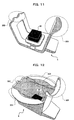
FIG. 11 is a view showing a conventional guide apparatus, and FIG. 12 is a view showing another conventional guide apparatus.
As shown in FIG. 11, a guide apparatus 5 has a wrist guide 201, a middle finger guide 202, and a non-contact sensor unit 40. The wrist guide 201 fixes the wrist of a user to be subjected to the vein authentication, middle finger guide 202 fixes the middle finger of the user, and non-contact sensor unit 40 photographs the palm of the user fixed by the wrist guide 201 and middle finger guide 202.
Further, as shown in FIG. 12, a guide apparatus 6 has a wrist guide 301′ a middle finger guide 302, a placement portion 303, and a non-contact sensor unit 40. The wrist guide 301 fixes the wrist of a user to be subjected to the vein authentication, middle finger guide 302 fixes the middle finger of the user, placement portion 303 guides the user's hand to be placed on the guide apparatus 6 in such a manner to spread his or her fingers, and non-contact sensor unit 40 photographs the palm of the user fixed by the wrist guide 301, middle finger guide 302, and placement portion 303.
As a prior art relating to the present invention, there is known a method and apparatus for positioning a living body (refer to, e.g., Patent Document 1: Jpn. Pat. Appln. Laid-Open Publication No. 11-47119)
However, in the guide apparatus 5, the position of the palm relative to the non-contact sensor unit 40 may change in the direction denoted by the arrow between the registration time and authentication time, as shown in FIG. 13 and, further, the degree of spread of the fingers may change between the registration time and authentication time. Further, in the guide apparatus 6, in the case where the width of the user's wrist is smaller than the width set by the wrist guide 301, the wrist guide 301 cannot fix the user's wrist as shown in FIG. 14, which may cause a change in the position of the user's wrist in the direction denoted by the arrow between the registration time and authentication time. As a result, the non-contact sensor unit 40 may photograph different portions of the palm between the registration time and authentication time. In this case, although the palm of the same user is subjected to the vein authentication, the vein pattern is determined to be different from that at the registration time, with the result that the relevant user is not authenticated.
In order to carry out the non-contact vein authentication smoothly, it is necessary to guide the user that he or she places his or her palm on the same position both at the registration time and authentication time. Further, the size of the palm or wrist differs greatly in individuals, so that a mechanism that enables alt users to place their palms on the same position relative to the non-contact sensor unit 40 is required.
SUMMARY OF THE INVENTION
The present invention has been made to solve the above problems, and an object thereof is to provide a guide apparatus, an image pickup apparatus, an image pickup system, and a guide method capable of guiding palms of various sizes to a position suitable for photographing.
To solve the above problem, according to a first aspect of the present invention, there is provided a guide apparatus that guides a palm to be photographed by an image pickup apparatus to a position suitable for photographing, including: a placement portion that has a planar surface on which the palm is placed in the image pickup direction of the image pickup apparatus and that supports the palm placed on the planar surface so that the palm can be photographed by the image pickup apparatus through an opening formed in the planar surface; a finger guide that is provided on the placement portion at the one end side of the opening and formed of two finger guide members with a predetermined distance therebetween and that positions a predetermined finger between the finger guide members; and a wrist guide that is provided on the placement portion at the other end side (opposite to the one end side) of the opening in a V-shaped manner with respect to the image pickup direction of the image pickup apparatus for supporting a wrist and that is movably arranged such that when the wrist is brought into contact with the V-shaped inclined surface, the wrist guide is moved by the load of wrist and guides the wrist in the inclined direction while moving the palm to a predetermined position with respect to the opening in cooperation with the finger guide.
According to a second aspect of the present invention, there is provided an image pickup apparatus, including: an image pickup section that photographs a palm; a placement portion that has a planar surface on which the palm is placed in the image pickup direction of the image pickup section and that supports the palm placed on the planar surface so that the palm can be photographed by the image pickup section through an opening formed in the planar surface; a finger guide that is provided on the placement portion at the one end side of the opening and that positions a predetermined finger placed on the placement portion; and a wrist guide that is provided on the placement portion at the other end side (opposite to the one end side) of the opening in a V-shaped manner with respect to the image pickup direction of the image pickup section for supporting a wrist and that is movably arranged such that when the wrist is brought into contact with the V-shaped inclined surface, the wrist guide is moved by the load of wrist and guides the wrist in the inclined direction while moving the palm to a predetermined position with respect to the opening in cooperation with the finger guide.
According to a third aspect of the present invention, there is provided an image pickup system, including: an image pickup section that photographs a palm; a placement portion that has a detection section for detecting the palm set at a position at which the image pickup section can photograph the palm and a planar surface on which the palm is placed in the image pickup direction of the image pickup section and that supports the palm placed on the planar surface so that the palm can be photographed by the image pickup section through an opening formed in the planar surface; a finger guide that is provided on the placement portion at the one end side of the opening and that positions a predetermined finger placed on the placement portion; a wrist guide that is provided on the placement portion at the other end side (opposite to the one end side) of the opening in a V-shaped manner with respect to the image pickup direction of the image pickup section for supporting a wrist and that is movably arranged such that when the wrist is brought into contact with the V-shaped inclined surface, the wrist guide is moved by the load of wrist and guides the wrist in the inclined direction while moving to position the palm to a predetermined position with respect to the opening in cooperation with the finger guide; and a control unit that allows the image pickup section to photograph the palm in the case where the detection section detects the palm.
According to a fourth aspect of the present invention, there is provided a guide method that guides a palm to a position suitable for photographing in the case where a camera provided in a casing is used to photograph, through an opening formed in the casing, the palm which is guided to the front of the opening, including: providing, at the one end side of the opening, a finger guide for positioning a predetermined finger, and providing, at the other end side (opposite to the one end side) of the opening, a wrist guide for positioning a wrist, wherein when the wrist is brought into contact with an inclined surface provided in a V-shaped manner with respect to the image pickup direction, the wrist guide is moved by the load of wrist and guides the wrist in the inclined direction while moving the palm to a predetermined position with respect to the opening in cooperation with the finger guide.
According to the present invention, a guide apparatus, an image pickup apparatus, an image pickup system, and a guide method capable of guiding palms of various sizes to a position suitable for photographing can be provided.
BRIEF DESCRIPTION OF THE DRAWINGS
FIG. 1 is a view showing an image pickup system according to an embodiment of the present invention;
FIG. 2 is a view showing the image pickup range in palm vein authentication;
FIG. 3 is a view showing a configuration of an image pickup apparatus according to the present embodiment;
FIG. 4 is a view showing a configuration of the image pickup apparatus according to the present embodiment;
FIG. 5 is a view showing a state of a wrist guide in the case where a comparatively thin wrist is placed thereon;
FIG. 6 is a view showing a state of a wrist guide in the case where a comparatively thick wrist is placed thereon;
FIG. 7 is a view showing a middle finger fixed in a middle finger guide;
FIG. 8 is a view showing a positional relationship between the middle finger and middle finger guide;
FIG. 9 is a view showing a configuration of a non-contact sensor unit;
FIG. 10 is a flowchart showing operation of non-contact vein authentication processing;
FIG. 11 is a view showing a conventional guide apparatus;
FIG. 12 is a view showing another conventional guide apparatus;
FIG. 13 is a view showing a problem posed in the guide apparatus of FIG. 11; and
FIG. 14 is a view showing a problem posed in the guide apparatus of FIG. 12.
DETAILED DESCRIPTION OF THE PREFERRED EMBODIMENTS
An embodiment of the present invention will be described below with reference to the accompanying drawings.
First, the outline of the present embodiment will be described. FIG. 1 is a view showing an image pickup system according to the present embodiment, and FIG. 2 is a view showing the image pickup range in palm vein authentication.
An image pickup system S includes an image pickup apparatus 1 (guide apparatus) and a personal computer 2 (control apparatus). The image pickup apparatus 1 and personal computer 2 are connected to each other by a USB cable 3. In the present embodiment, it is assumed that non-contact vein authentication is conducted for a user to login to the personal computer 2, and that the user has previously registered, in the personal computer 2, a vein pattern within a vein range R shown in FIG. 2 of a palm of his or her left or right hand by using the image pickup apparatus 1 and performs authentication at the is login time using the palm of the same hand.
Further, in the present embodiment, it is assumed that processing concerning the non-contact vein authentication and power supply to the image pickup apparatus 1 are made by the personal computer 2 using the USB cable 3. The personal computer 2 may be any apparatus, such as an ATM, as long as it can execute processing concerning the non-contact vein authentication. Further, the USB cable 3 may be any configuration as long as it can connect the image pickup apparatus 1 to an apparatus that executes processing concerning the vein authentication.
A description will next be given of the image pickup apparatus according to the present embodiment. FIGS. 3 and 4 are views showing a configuration of the image pickup apparatus according to the present embodiment. FIG. 3 is a top perspective view of the image pickup apparatus, and FIG. 4 is a side perspective view thereof.
As shown in FIGS. 3 and 4, the image pickup apparatus 1 has a placement portion 10, a wrist guide 20 provided on the placement portion 10, a middle finger guide 30 (finger guide) provided on the placement portion 10, a non-contact sensor unit 40 having a camera 40 a, and a detachable USB cable 3. The non-contact sensor unit 40 has a not-shown USB connection portion.
The placement portion 10, wrist guide 20, and middle finger guide 30 constitutes a palm guide apparatus in the present embodiment.
The placement portion 10 has a planar surface H perpendicular to the image pickup direction of the image pickup apparatus 1 (image pickup direction of the camera 40 a) and supports a palm placed on the planar surface H such that the camera 40 a can photograph the palm through an opening portion W formed in the planar surface H. The opening portion W is formed above the non-contact sensor unit 40 and is made to have a size slightly larger than an image pickup range F of the non-contact sensor unit 40 at a portion corresponding to the image pickup range F. The non-contact sensor unit 40 is has a camera 40 a and photographs the vain pattern on the palm within the image pickup range F.
The wrist guide 20 has, at the center thereof, a flat portion 20 a and has, at both ends thereof projection portions 20 b and 20 b having inclined surfaces VF facing each other. The wrist guide 20 is so formed as to project upward from the planar surface H. Further, the wrist guide 20 is so supported by an appropriate portion (support member) 1 of the casing of the image pickup apparatus 1 through a compression coil spring 50 attached to the lower surface of the wrist guide 20 as to be movable in the up-down direction. The height of the flat portion 20 a of the wrist guide 20 is substantially the same as the height of the placement portion 10 and, when the wrist is placed on the flat portion 20 a, the wrist guide 20 moves downward until the wrist or its surrounding portion is brought into contact with the planar surface of the placement portion 10.
Then, in cooperation with the finger guide 30, the wrist guide 20 guides the wrist downward for positioning until the wrist is brought into contact with the planar surface so that the palm placed on the placement portion 10 is adequately photographed. The inclined surfaces VF of the projection portions 20 b and 20 b are inclined such that the distance between the projection portions 20 b and 20 b is narrower at the lower portion than at the upper portion. Further, in the present embodiment, the two projection portions 20 b and 20 b of the wrist guide 20 project from the planar surface H such that their inclined surfaces on which the wrist is placed are away from each other. That is, although the projection portions 20 b and 20 b are so formed as to project upward from two holes formed in the planar surface H, the hole may be formed in the planar surface H such that the entire wrist guide 20 as viewed from the above faces outside the placement portion, as long as the height of flat portion 20 a of the wrist guide 20 is the same as the height of the planar surface H.
The middle finger guide 30 is constituted by two cone-like projections (finger guide members) 30 a and 30 a. The projections 30 a and 30 a are provided on the placement portion with a predetermined distance therebetween so that the middle finger is positioned to the center therebetween.
The above wrist guide 20, middle finger guide 30, and non-contact sensor unit 40 are arranged such that the centers thereof are arranged on a center line C of the placement portion 10 as shown in FIG. 3. By placing a hand on the placement portion 10 such that the wrist is fixed by the wrist guide 20 and middle finger is fixed by the middle finger guide 30, the palm can be set at the same position both at the registration time and authentication time.
Further, by fixing the middle finger on the center line C, it is possible for a user to correctly position the palm regardless of whether a left or right hand is placed. Further, when the palm is placed on the placement portion, the palm is fixed in an opened state, thereby preventing the degree of spread of the fingers from changing between the registration time and authentication time. Furthermore, in this configuration, the thumb and little fingers are placed on the placement portion 10, and middle finger and wrist are fixed, so that the angle of the palm relative to the non-contact sensor unit 40 is always kept constant. For example, the palm face is set parallel to the opening plane of the opening portion W.
It is assumed in the following description that the middle finger guide 30 side and wrist guide 20 side of the placement portion 10 are referred to as “front side” and “rear side” thereof. The middle finger guide 30 may be a guide for another finger.
A description will next be given of operation of the wrist guide of the image pickup apparatus. FIG. 5 is a view showing a state of the wrist guide in the case where a comparatively thin wrist is placed thereon, and FIG. 6 is a view showing a state of the wrist guide in the case where a comparatively thick wrist is placed thereon.
As shown in FIG. 5, when a comparatively thin wrist H1, i.e., a thin wrist H1 having a width which can be accommodated within the shortest distance (distance between the projection portions 20 b and 20 b at their top positions) between the left and right projection portions 20 b and 20 b is placed on the wrist guide 20, the wrist contacts the planar surface H, so that the wrist guide 20 does not move downward. Note that even in the configuration where the entire wrist guide 20 is exposed from the planar surface H, the wrist guide 20 does not move downward, because the height of the flat portion 20 a of the wrist guide 20 is made equal to the height of the planar surface H of the placement portion to cause the portion surrounding the wrist to contact the planar surface of the placement portion 10.
On the other hand, as shown in FIG. 6, when a comparatively thick wrist H2, i.e., a thick wrist H2 having a width larger than the shortest distance (distance between the projection portions 20 b and 20 b at their top positions) between the left and right projection portions 20 b and 20 b is placed on the wrist guide 20, the wrist guide 20 is pressed down until the wrist H2 contacts the planar surface H of the placement portion 10, so that the distance between the left and right projection portions 20 b of the wrist guide 20 at the height of the planar surface H is made larger. In such a manner, the wrist guide 20 can accommodate wrists of various sizes.
With the above configuration, it is possible to guide the wrist on the center line C regardless of the size of the wrist, as well as to make constant the distance between the palm and non-contact sensor unit 40 in the image pickup direction.
In the present embodiment, the distance between the left and right inclined surfaces of the wrist guide 20 is set to correspond to a thin wrist, and the wrist guide 20 having the left and right projection portions 20 b is constituted as one unit and thus the left and right projection portions 20 b are pressed down by the same degree. Although the wrist guide 20 is configured to be pressed down in the present embodiment, another configuration may be employed. For example, the left and right projection portions 20 b may slide in the outside is direction by the same distance.
A description will next be given of a configuration of the middle finger guide and its effect. FIG. 7 is a view showing a middle finger fixed in the middle finger guide, and FIG. 8 is a view showing a positional relationship between the middle finger and middle finger guide. FIG. 7 shows a state where the image pickup apparatus is viewed from the front.
As shown in FIG. 7, the cone- like projections 30 a and 30 a of the middle finger guide 30 position a middle finger M to substantially the center therebetween. Further, the inclined surfaces of the cone- like projections 30 a and 30 a allows the middle finger guide 30 to accommodate middle fingers of various sizes. For example, it is possible to fix a middle finger thicker than assumed in the middle of the inclined surfaces of the projections 30 a and 30 a as shown in FIG. 7.
Further, as shown in FIG. 8, the middle finger guide 30 holds a portion between a proximal interphalangeal joint (PIP joint) P of the middle finger and base thereof, especially, a portion B1 at which the width of the proximal phalanx B becomes thinner, thereby preventing movement of the middle finger in the direction denoted by the arrow. At this time, at least a portion of the thumb between its fingertip and interphalangeal joint (IP joint) I and a portion of the little finger between its fingertip and distal interphalangeal joint (DIP joint) D are placed on the placement portion 10.
According to the present embodiment having the above configuration, it is possible for the guide apparatus to accommodate hands of various sizes, as well as to make constant the degree of spread of fingers and position/angle of the palm relative to the non-contact sensor unit 40. As a result, the non-contact sensor unit 40 can photograph the palm at the same position and at the same angle both at the registration time and authentication time.
A description will next be given of a configuration of the non-contact sensor unit. FIG. 9 is a view showing a configuration of the non-contact sensor is unit.
The non-contact sensor unit 40 has an infrared sensor 401 (image pickup section corresponding to the camera 40 a), a condenser lens 402 (image pickup section corresponding to the camera 40 a), a near-infrared light-emitting device 403 (image pickup section corresponding to the camera 40 a), a distance sensor 404 (detection section), and an infrared filter 405. The near-infrared light-emitting device 403 emits a near-infrared ray in an upward direction to irradiate the palm placed on the image pickup apparatus 1 with the near-infrared ray.
The condenser lens 402 collects a light irradiated to the palm on the image pickup range F shown in FIG. 1 by the near-infrared light-emitting device 403 and reflected therefrom on the infrared sensor 401. The distance sensor 404 detects an object on the non-contact sensor unit 40 and measures the distance between the object and sensor unit 40. The infrared filter 405 shields visible light.
A description will next be given of non-contact vein authentication processing performed by the image pickup system according to the embodiment. FIG. 10 is a flowchart showing operation of non-contact vein authentication processing. It is assumed that control for the non-contact sensor unit and authentication processing are performed by the personal computer 2 and that a vein pattern image of a target user has previously been registered in the personal computer 2.
The personal computer 2 uses the distance sensor 404 to perform detection (S101) to determine whether there exists an object (palm) on the non-contact sensor unit 40 (S102).
When an object has been detected by the distance sensor 404 (YES in S102), the personal computer 2 uses the distance sensor 404 to measure the distance between the distance sensor 404 and object (S103) and determines whether the measured distance is suitable for photographing a vein pattern (S104).
When determining that the distance between the non-contact sensor unit 40 and object is appropriate (YES in S104), the personal computer 2 uses the infrared sensor 401 to photograph the object (S105) and compares the photographed vein pattern image and registered vein pattern image (S106) to determine whether they match each other (S107).
When the photographed vein pattern image and registered vein pattern image match each other (YES in S107), the personal computer 2 authenticates the user (S108).
On the other hand, when the photographed vein pattern image and registered vein pattern do not match each other (NO in S107), the personal computer 2 does not authenticate the user (S109).
When the distance between the non-contact sensor unit 40 and object is not appropriate (NO in S104), the personal computer 2 uses the distance sensor 404 to detect the distance once again (S101).
When an object is not detected by the distance sensor 404 (NO in S102), the personal computer 2 uses the distance sensor 404 to detect the distance once again (S101).
With the configuration and operation described above, the image pickup system S performs user authentication using the vein pattern of the user's palm. In the above authentication, the palm is guided to the same position both at the registration time and authentication time by using the image pickup apparatus 1, thereby reducing the probability that one person is erroneously recognized as another person.
Further, the personal computer 2 uses the distance sensor 404 to detect the distance between the non-contact sensor unit 40 and object and determine whether the detected distance is appropriate, thereby detecting whether the palm is placed on the placement portion 10.
The present embodiment can be applied not only to the non-contact vein authentication but also to contact type vein authentication. Further, the image is pickup apparatus 1 according to the present embodiment may photograph not only the vein pattern but also lines of the palm. Further, the wrist guide 20 may be used, in place of the distance sensor 404, to detect the placement of the palm on the image pickup apparatus 1. In this case, the placement of the palm on the image pickup apparatus 1 is detected by depression of the wrist guide 20.
As described above, the image pickup apparatus (photographing apparatus) has the placement portion having the opening portion, finger guide, wrist guide, and photographing device provided in the opening portion in order to guide a palm to be photographed to a position suitable for photographing. When a user's left or right hand is placed on the placement portion, at least the second joints of a plurality of fingers are placed on the planar surface of the placement portion, and the middle finger is positioned by the finger guide. The wrist guide, which is provided on the opposite side of the finger guide on the upper surface of the image pickup apparatus with respect to the opening portion, has a pair of inclined surfaces and, when the palm is placed on the placement portion, the both end sides of the wrist contact the inclined surfaces to be positioned. Further, upon contact of the wrist with the wrist guide, the wrist guide moves downward so as to keep the palm parallel to the opening plane of the opening portion.

Claims (20)

1. A guide apparatus that guides a palm to be photographed by an image pickup apparatus to a position suitable for photographing, comprising:
a placement portion that has a planar surface on which the palm is placed in an image pickup direction of the image pickup apparatus and that supports the palm placed on the planar surface so that the palm can be photographed by the image pickup apparatus through an opening formed in the planar surface;
a finger guide that is provided on the placement portion at the one end side of the opening and that positions a predetermined finger placed on the placement portion; and
a wrist guide that is provided on the placement portion at the other end side (opposite to the one end side) of the opening in a V-shaped manner with respect to the image pickup direction of the image pickup apparatus that supports a wrist and that is movably arranged such that when the wrist is brought into contact with a V-shaped inclined surface, the wrist guide is moved by a load of the wrist and guides the wrist in an inclined direction while moving the palm to a predetermined position with respect to the opening in cooperation with the finger guide.
2. The guide apparatus according to claim 1, wherein
the wrist guide is supported by an elastic member and is moved in the direction perpendicular to a planar direction of the planar surface.
3. The guide apparatus according to claim 1, wherein
the finger guide is constituted by two finger guide members arranged with a predetermined distance therebetween, and
the predetermined finger is positioned between the finger guide members.
4. The guide apparatus according to claim 3, wherein
the finger guide members each have a cone-like shape.
5. The guide apparatus according to claim 1, wherein
the finger guide provided on the placement portion holds a middle finger as the predetermined finger and is provided on the placement portion so as to guide the palm to a suitable position for photographing with respect to the opening.
6. The guide apparatus according to claim 5, wherein
the finger guide provided on the placement portion holds a portion between a proximal interphalangeal joint of the middle finger and base thereof so as to guide the palm to a suitable position for photographing with respect to the opening.
7. The guide apparatus according to claim 1, wherein
the placement portion supports at least a portion of a thumb between its fingertip and interphalangeal joint and a portion of a little finger between its fingertip and distal interphalangeal joint.
8. An image pickup apparatus, comprising:
an image pickup section that photographs a palm;
a placement portion that has a planar surface on which the palm is placed in an image pickup direction of the image pickup apparatus and that supports the palm placed on the planar surface so that the palm can be photographed by the image pickup section through an opening formed in the planar surface;
a finger guide that is provided on the placement portion at the one end side of the opening and that positions a predetermined finger placed on the placement portion; and
a wrist guide that is provided on the placement portion at the other end side (opposite to the one end side) of the opening in a V-shaped manner with respect to the image pickup direction of the image pickup section that supports a wrist and that is movably arranged such that when the wrist is brought into contact with a V-shaped inclined surface, the wrist guide is moved by a load of the wrist and guides the wrist in an inclined direction while moving the palm to a predetermined position with respect to the opening in cooperation with the finger guide.
9. The image pickup apparatus according to claim 8, wherein
the wrist guide is supported by an elastic member and is moved in the direction perpendicular to a planar direction of the planar surface.
10. The image pickup apparatus according to 8, wherein
the finger guide is constituted by two finger guide members arranged with a predetermined distance therebetween, and
the predetermined finger is positioned between the finger guide members.
11. The image pickup apparatus according to claim 10, wherein
the finger guide members each have a cone-like shape.
12. The image pickup apparatus according to claim 8, wherein
the finger guide holds a middle finger as the predetermined finger and is provided on the placement portion so as to guide the palm to a suitable position for photographing with respect to the opening.
13. The image pickup apparatus according to claim 12, wherein
the finger guide holds a portion between a proximal interphalangeal joint of the middle finger and base thereof so as to guide the palm to a suitable position for photographing with respect to the opening.
14. The image pickup apparatus according to claim 8, wherein
the placement portion supports at least a portion of a thumb between its fingertip and interphalangeal joint and a portion of a little finger between its fingertip and distal interphalangeal joint.
15. The image pickup apparatus according to claim 8,
wherein
the image pickup section photographs an infrared image.
16. An image pickup system, comprising:
an image pickup section that photographs a palm;
a placement portion that has a detection section for detecting the palm set at a position at which an image pickup section can photograph the palm and a planar surface on which the palm is placed in the image pickup direction of the image pickup section and that supports the palm placed on the planar surface so that the palm can be photographed by the image pickup section through an opening formed in the planar surface;
a finger guide that is provided on the placement portion at the one end side of the opening and that positions a predetermined finger placed on the placement portion;
a wrist guide that is provided on the placement portion at the other end side (opposite to the one end side) of the opening in a V-shaped manner with respect to the image pickup direction of the image pickup section that supports a wrist and that is movably arranged such that when the wrist is brought into contact with a V-shaped inclined surface, the wrist guide is moved by a load of the wrist and guides the wrist in an inclined direction while moving the palm to a predetermined position with respect to the opening in cooperation with the finger guide; and
a control unit that allows the image pickup section to photograph the palm in the case where the detection section detects the palm.
17. The image pickup system according to claim 16, wherein
the wrist guide is supported by an elastic member and is moved in the direction perpendicular to the planar direction of the planar surface.
18. The image pickup system according to claim 16, wherein
the finger guide is constituted by two finger guide members arranged with a predetermined distance therebetween, and
the predetermined finger is positioned between the finger guide members.
19. The image pickup system according to claim 18, wherein
the finger guide members each have a cone-like shape.
20. A guide method that guides a palm to a position suitable for photographing in the case where a camera provided in a casing is used to photograph, through an opening formed in the casing, the palm which is guided to the front of the opening, comprising:
providing, at the one end side of the opening, a finger guide for positioning a predetermined finger, and
providing, at the other end side (opposite to the one end side) of the opening, a wrist guide for positioning a wrist, wherein
when the wrist is brought into contact with an inclined surface provided in a V-shaped manner with respect to an image pickup direction, the wrist guide is moved by a load of the wrist and guides the wrist in an inclined direction while moving the palm to a predetermined position with respect to the opening in cooperation with the finger guide.
US12/195,672 2007-11-12 2008-08-21 Guide apparatus, image pickup apparatus, image pickup system, and guide method Expired - Fee Related US8326005B2 (en)

Applications Claiming Priority (2)

Application Number Priority Date Filing Date Title
JP2007-292759 2007-11-12
JP2007292759A JP4957514B2 (en) 2007-11-12 2007-11-12 GUIDE DEVICE, IMAGING DEVICE, IMAGING SYSTEM, GUIDING METHOD

Publications (2)

Publication Number Publication Date
US20090123041A1 US20090123041A1 (en) 2009-05-14
US8326005B2 true US8326005B2 (en) 2012-12-04

Family

ID=40623742

Family Applications (1)

Application Number Title Priority Date Filing Date
US12/195,672 Expired - Fee Related US8326005B2 (en) 2007-11-12 2008-08-21 Guide apparatus, image pickup apparatus, image pickup system, and guide method

Country Status (2)

Country Link
US (1) US8326005B2 (en)
JP (1) JP4957514B2 (en)

Cited By (3)

* Cited by examiner, † Cited by third party
Publication number Priority date Publication date Assignee Title
US20130287268A1 (en) * 2010-12-28 2013-10-31 Fujitsu Limited Biometric authentication device, biometric authentication method, and non-transitory computer-readable recording medium
US20130294658A1 (en) * 2011-02-23 2013-11-07 Fujitsu Frontech Limited Apparatus and method for acquiring biometric information
US20160287144A1 (en) * 2014-01-31 2016-10-06 Fujitsu Frontech Limited Image capturing apparatus and authentication apparatus

Families Citing this family (16)

* Cited by examiner, † Cited by third party
Publication number Priority date Publication date Assignee Title
JP2009189446A (en) * 2008-02-13 2009-08-27 Fujitsu Ltd Vein imaging apparatus
US8803963B2 (en) * 2008-09-22 2014-08-12 Kranthi Kiran Pulluru Vein pattern recognition based biometric system and methods thereof
JP5513071B2 (en) * 2009-10-26 2014-06-04 株式会社プロフィールド Information processing apparatus, information processing method, and program
JP5427551B2 (en) * 2009-10-30 2014-02-26 株式会社プロフィールド Information processing apparatus, information processing method, and program
EP2677490B1 (en) 2011-02-15 2021-04-28 Fujitsu Frontech Limited Authentication device, authentication program, and authentication method
JP5831018B2 (en) * 2011-07-29 2015-12-09 富士通株式会社 Biometric authentication device and method for adjusting user's hand position in biometric authentication device
WO2013046365A1 (en) * 2011-09-28 2013-04-04 富士通フロンテック株式会社 Guidance device, biometric information acquisition device, and registration device
KR101540890B1 (en) * 2014-10-08 2015-07-30 이호석 Non-contact Type Biometric Apparatus with Function of Multi Recognitions
US10657399B2 (en) * 2014-10-24 2020-05-19 Nec Corporation Biometric imaging device, biometric imaging method and program
US10445714B2 (en) * 2015-01-29 2019-10-15 Ncr Corporation Gesture-based signature capture
JP6589309B2 (en) * 2015-03-16 2019-10-16 富士通株式会社 Terminal device, biometric authentication program, and biometric authentication method
US10325142B2 (en) * 2015-04-23 2019-06-18 Shenzhen GOODIX Technology Co., Ltd. Multifunction fingerprint sensor
US11587363B2 (en) * 2019-12-09 2023-02-21 Iris-Gmbh Infrared & Intelligent Sensors Sensor system for checking palm vein patterns
KR102370436B1 (en) * 2020-06-22 2022-03-04 주식회사 바디프랜드 Massage device with blood pressure measurement module for measuring blood pressure
BR102020021765A2 (en) * 2020-10-23 2022-05-03 José Antonio Martins Palmar device for non-invasive collection of biomarkers in living beings
CN217061035U (en) * 2022-03-24 2022-07-26 腾讯科技(深圳)有限公司 Palm brushing equipment

Citations (28)

* Cited by examiner, † Cited by third party
Publication number Priority date Publication date Assignee Title
US5483601A (en) * 1992-02-10 1996-01-09 Keith Faulkner Apparatus and method for biometric identification using silhouette and displacement images of a portion of a person's hand
JPH1147119A (en) 1997-08-06 1999-02-23 Kurabo Ind Ltd Method and device for positioning living body
US6175407B1 (en) * 1998-12-17 2001-01-16 Identix Incorporated Apparatus and method for optically imaging features on the surface of a hand
US20020048014A1 (en) * 2000-09-20 2002-04-25 Hitachi, Ltd. Personal identification system
JP2002298128A (en) 2001-04-03 2002-10-11 Nippon Telegr & Teleph Corp <Ntt> Fingerprint measuring device
US20030072475A1 (en) * 2001-10-09 2003-04-17 Bmf Corporation Verification techniques for biometric identification systems
US20030103686A1 (en) * 2001-12-04 2003-06-05 Canon Kabushiki Kaisha Image input device
US20040022421A1 (en) * 2002-07-31 2004-02-05 Fujitsu Limited Processor with personal verification function and operating device
US20040264742A1 (en) * 2002-09-25 2004-12-30 Zhang Dapeng David Method of palm print identification
US20050047632A1 (en) * 2003-08-26 2005-03-03 Naoto Miura Personal identification device and method
US20050094855A1 (en) * 2003-10-29 2005-05-05 Proano Cesar H. Fingerprint imaging using a flat panel detector
US6937748B1 (en) * 1999-09-10 2005-08-30 Ultra-Scan Corporation Left hand right hand invariant dynamic finger positioning guide
US20050273027A1 (en) * 2002-02-25 2005-12-08 Saebo, Inc. Dynamic hand splint
JP2006099493A (en) 2004-09-30 2006-04-13 Hitachi Omron Terminal Solutions Corp Image pickup device or individual authentication device
US20060211964A1 (en) * 2004-12-10 2006-09-21 Saebo, Inc. Dynamic hand splints
JP2006318018A (en) 2005-05-10 2006-11-24 Nec Infrontia Corp Fingerprint reader
JP2006331239A (en) 2005-05-30 2006-12-07 Hitachi Omron Terminal Solutions Corp Personal identification device, and personal identification system
JP2007280298A (en) 2006-04-11 2007-10-25 Oki Electric Ind Co Ltd Automatic transaction apparatus
US20070270666A1 (en) * 2006-05-16 2007-11-22 Seiko Epson Corporation Biological Information Acquisition Device, Method for Acquiring Biological Information, and Biometrics Device
US20080034459A1 (en) * 2004-07-22 2008-02-14 Nordt Development Company, Llc Wrist support
US20080192988A1 (en) * 2006-07-19 2008-08-14 Lumidigm, Inc. Multibiometric multispectral imager
US20080226136A1 (en) * 2006-09-14 2008-09-18 Fujitsu Limited Living body guidance control method for a biometrics authentication device, and biometrics authentication device
US7431702B2 (en) * 2001-07-26 2008-10-07 Niels Rahe-Meyer Device for examination of the motor system of the human or animal body
US7580552B2 (en) * 2004-06-28 2009-08-25 Fujitsu Limited Image capturing apparatus for palm authentication
US7697730B2 (en) * 2004-07-30 2010-04-13 Fujitsu Limited Guidance screen control method of biometrics authentication device, biometrics authentication device, and program for same
US7725733B2 (en) * 2004-10-08 2010-05-25 Fujitsu Limited Biometrics authentication method and biometrics authentication device
US7978259B2 (en) * 2006-03-03 2011-07-12 Fujitsu Limited Image capturing apparatus for guiding light emitted from a plurality of light emitting devices
US8000503B2 (en) * 2004-10-08 2011-08-16 Fujitsu Limited Biometrics authentication system registration method, biometrics authentication system, and program for same

Family Cites Families (2)

* Cited by examiner, † Cited by third party
Publication number Priority date Publication date Assignee Title
JP2906312B2 (en) * 1993-05-12 1999-06-21 シャープ株式会社 Input device
JP4281272B2 (en) * 2001-09-14 2009-06-17 三菱電機株式会社 Fingerprint image imaging method, fingerprint image acquisition method, fingerprint image imaging device, and personal identification device

Patent Citations (30)

* Cited by examiner, † Cited by third party
Publication number Priority date Publication date Assignee Title
US5483601A (en) * 1992-02-10 1996-01-09 Keith Faulkner Apparatus and method for biometric identification using silhouette and displacement images of a portion of a person's hand
US6101405A (en) * 1997-06-08 2000-08-08 Kurashiki Boseki Kabushiki Kaisha Method and device for positioning a living body
JPH1147119A (en) 1997-08-06 1999-02-23 Kurabo Ind Ltd Method and device for positioning living body
US6175407B1 (en) * 1998-12-17 2001-01-16 Identix Incorporated Apparatus and method for optically imaging features on the surface of a hand
US6937748B1 (en) * 1999-09-10 2005-08-30 Ultra-Scan Corporation Left hand right hand invariant dynamic finger positioning guide
US20020048014A1 (en) * 2000-09-20 2002-04-25 Hitachi, Ltd. Personal identification system
JP2002298128A (en) 2001-04-03 2002-10-11 Nippon Telegr & Teleph Corp <Ntt> Fingerprint measuring device
US7431702B2 (en) * 2001-07-26 2008-10-07 Niels Rahe-Meyer Device for examination of the motor system of the human or animal body
US20030072475A1 (en) * 2001-10-09 2003-04-17 Bmf Corporation Verification techniques for biometric identification systems
US20030103686A1 (en) * 2001-12-04 2003-06-05 Canon Kabushiki Kaisha Image input device
US20050273027A1 (en) * 2002-02-25 2005-12-08 Saebo, Inc. Dynamic hand splint
US20040022421A1 (en) * 2002-07-31 2004-02-05 Fujitsu Limited Processor with personal verification function and operating device
US20040264742A1 (en) * 2002-09-25 2004-12-30 Zhang Dapeng David Method of palm print identification
US20050047632A1 (en) * 2003-08-26 2005-03-03 Naoto Miura Personal identification device and method
US20050094855A1 (en) * 2003-10-29 2005-05-05 Proano Cesar H. Fingerprint imaging using a flat panel detector
US7580552B2 (en) * 2004-06-28 2009-08-25 Fujitsu Limited Image capturing apparatus for palm authentication
US20080034459A1 (en) * 2004-07-22 2008-02-14 Nordt Development Company, Llc Wrist support
US7697730B2 (en) * 2004-07-30 2010-04-13 Fujitsu Limited Guidance screen control method of biometrics authentication device, biometrics authentication device, and program for same
JP2006099493A (en) 2004-09-30 2006-04-13 Hitachi Omron Terminal Solutions Corp Image pickup device or individual authentication device
US7725733B2 (en) * 2004-10-08 2010-05-25 Fujitsu Limited Biometrics authentication method and biometrics authentication device
US8000503B2 (en) * 2004-10-08 2011-08-16 Fujitsu Limited Biometrics authentication system registration method, biometrics authentication system, and program for same
US20060211964A1 (en) * 2004-12-10 2006-09-21 Saebo, Inc. Dynamic hand splints
JP2006318018A (en) 2005-05-10 2006-11-24 Nec Infrontia Corp Fingerprint reader
JP2006331239A (en) 2005-05-30 2006-12-07 Hitachi Omron Terminal Solutions Corp Personal identification device, and personal identification system
US7978259B2 (en) * 2006-03-03 2011-07-12 Fujitsu Limited Image capturing apparatus for guiding light emitted from a plurality of light emitting devices
JP2007280298A (en) 2006-04-11 2007-10-25 Oki Electric Ind Co Ltd Automatic transaction apparatus
US20070270666A1 (en) * 2006-05-16 2007-11-22 Seiko Epson Corporation Biological Information Acquisition Device, Method for Acquiring Biological Information, and Biometrics Device
US20080192988A1 (en) * 2006-07-19 2008-08-14 Lumidigm, Inc. Multibiometric multispectral imager
US7899217B2 (en) * 2006-07-19 2011-03-01 Lumidign, Inc. Multibiometric multispectral imager
US20080226136A1 (en) * 2006-09-14 2008-09-18 Fujitsu Limited Living body guidance control method for a biometrics authentication device, and biometrics authentication device

Non-Patent Citations (1)

* Cited by examiner, † Cited by third party
Title
Japanese Office Action dated Nov. 8, 2011 issued in corresponding Japanese Patent Application No. 2007-292759.

Cited By (4)

* Cited by examiner, † Cited by third party
Publication number Priority date Publication date Assignee Title
US20130287268A1 (en) * 2010-12-28 2013-10-31 Fujitsu Limited Biometric authentication device, biometric authentication method, and non-transitory computer-readable recording medium
US9189684B2 (en) * 2010-12-28 2015-11-17 Fujitsu Limited Biometric authentication device, biometric authentication method, and non-transitory computer-readable recording medium
US20130294658A1 (en) * 2011-02-23 2013-11-07 Fujitsu Frontech Limited Apparatus and method for acquiring biometric information
US20160287144A1 (en) * 2014-01-31 2016-10-06 Fujitsu Frontech Limited Image capturing apparatus and authentication apparatus

Also Published As

Publication number Publication date
JP4957514B2 (en) 2012-06-20
JP2009122729A (en) 2009-06-04
US20090123041A1 (en) 2009-05-14

Similar Documents

Publication Publication Date Title
US8326005B2 (en) Guide apparatus, image pickup apparatus, image pickup system, and guide method
JP6353927B2 (en) Blood vessel imaging device and personal authentication system
JP4095659B2 (en) Vein authentication device
JP5831018B2 (en) Biometric authentication device and method for adjusting user&#39;s hand position in biometric authentication device
KR100746194B1 (en) Image-taking device and personal authentication device
TWI407377B (en) Biometric information processing device
KR100918286B1 (en) Living body guidance control method for a biometrics authentication device, and biometrics authentication device
JP4997305B2 (en) Finger vein authentication device
US20100085151A1 (en) Authentication apparatus
JP3925338B2 (en) Personal authentication device
JP5047773B2 (en) Finger vein imaging device and personal authentication device
JP2006331441A (en) Image capturing device or personal authentication device
JP2007020828A (en) Imaging device
KR101547659B1 (en) A finger vein recognition apparatus and a terminal with the same
JP2003187235A (en) Finger vein recognition device
JP4960029B2 (en) Personal authentication device
JP4945505B2 (en) Biological information processing device
JP4933585B2 (en) Information terminal
JP6759065B2 (en) Blood vessel imaging device and personal authentication system
JP5768441B2 (en) Biological information acquisition apparatus, biological information acquisition method, and biological information acquisition program
JP7219429B2 (en) Biometric authentication device and biometric authentication method
JP4897014B2 (en) Personal authentication device
CN114258561A (en) Imaging device and authentication device
GB2565446A (en) Biometric authentication device
JP2012221011A (en) Personal authentication device using biological information

Legal Events

Date Code Title Description
AS Assignment

Owner name: FUJITSU LIMITED, JAPAN

Free format text: ASSIGNMENT OF ASSIGNORS INTEREST;ASSIGNOR:TANI, SHIRO;REEL/FRAME:021440/0975

Effective date: 20080728

FEPP Fee payment procedure

Free format text: PAYOR NUMBER ASSIGNED (ORIGINAL EVENT CODE: ASPN); ENTITY STATUS OF PATENT OWNER: LARGE ENTITY

STCF Information on status: patent grant

Free format text: PATENTED CASE

FPAY Fee payment

Year of fee payment: 4

FEPP Fee payment procedure

Free format text: MAINTENANCE FEE REMINDER MAILED (ORIGINAL EVENT CODE: REM.); ENTITY STATUS OF PATENT OWNER: LARGE ENTITY

LAPS Lapse for failure to pay maintenance fees

Free format text: PATENT EXPIRED FOR FAILURE TO PAY MAINTENANCE FEES (ORIGINAL EVENT CODE: EXP.); ENTITY STATUS OF PATENT OWNER: LARGE ENTITY

STCH Information on status: patent discontinuation

Free format text: PATENT EXPIRED DUE TO NONPAYMENT OF MAINTENANCE FEES UNDER 37 CFR 1.362

FP Lapsed due to failure to pay maintenance fee

Effective date: 20201204